Table o f Content s
12. Three-Dimensional Object Representations
Donald D. Hearn/M. Pauline Baker, Warren Carithers Three-Dimensional Object Representations Color
Donald D. Hearn/M. Pauline Baker, Warren Carithers
13. Spline Representations
Donald D. Hearn/M. Pauline Baker, Warren Carithers
14. Visible-Surface
Donald D. Hearn/M. Pauline Baker, Warren Carithers
15
Donald D. Hearn/M. Pauline Baker, Warren Carithers
Models and Surface-Rendering
Donald D. Hearn/M. Pauline Baker, Warren Carithers 16. Texturing and Surface-Detail Methods
Donald D. Hearn/M. Pauline Baker, Warren Carithers
Donald D. Hearn/M. Pauline Baker, Warren Carithers
17.
Donald D. Hearn/M. Pauline Baker, Warren Carithers
Hearn/M. Pauline Baker, Warren Carithers
Donald D. Hearn/M. Pauline Baker, Warren Carithers
Donald D. Hearn/M. Pauline Baker, Warren Carithers
Donald D. Hearn/M. Pauline Baker, Warren Carithers
Donald D. Hearn/M. Pauline Baker, Warren Carithers
Donald D. Hearn/M. Pauline Baker, Warren Carithers 21. Algorithmic Modeling
Donald D. Hearn/M. Pauline Baker, Warren Carithers
Donald D. Hearn/M. Pauline Baker, Warren Carithers
22. Visualization of Data Sets
Donald D. Hearn/M. Pauline Baker, Warren Carithers
Visualization of Data Sets Color Plates
Donald D. Hearn/M. Pauline Baker, Warren Carithers
Appendix: Mathematics for Computer Graphics 737
Donald D. Hearn/M. Pauline Baker, Warren Carithers
Appendix: Graphics File Formats
Donald D. Hearn/M. Pauline Baker, Warren Carithers
Bibliography
Donald D. Hearn/M. Pauline Baker, Warren Carithers
773
This page intentionally left blank
Thepowerandutilityofcomputergraphicsiswidelyrecognized,andabroadrangeofgraphicshardwareandsoftwaresystemsisnowavailableforapplicationsinvirtually allfields.Graphicscapabilitiesforbothtwo-dimensionalandthreedimensionalapplicationsarenowcommon,evenongeneral-purpose computersandhandheldcalculators.Withpersonalcomputers,we canuseavarietyofinteractiveinputdevicesandgraphicssoftware packages.Forhigher-qualityapplications,wecanchoosefromanumberofsophisticatedspecial-purposegraphicshardwaresystemsand technologies.Inthischapter,weexplorethebasicfeaturesofgraphics hardwarecomponentsandgraphicssoftwarepackages.
Basicdesignofamagnetic-deflection
1 VideoDisplayDevices
Typically,theprimaryoutputdeviceinagraphicssystemisavideomonitor. Historically,theoperationofmostvideomonitorswasbasedonthestandard cathode-raytube (CRT)design,butseveralothertechnologiesexist.Inrecent years, flat-panel displayshavebecomesignificantlymorepopularduetotheir reducedpowerconsumptionandthinnerdesigns.
RefreshCathode-RayTubes
Figure1illustratesthebasicoperationofaCRT.Abeamofelectrons( cathode rays),emittedbyanelectrongun,passesthroughfocusinganddeflectionsystems thatdirectthebeamtowardspecifiedpositionsonthephosphor-coatedscreen. Thephosphorthenemitsasmallspotoflightateachpositioncontactedbythe electronbeam.Becausethelightemittedbythephosphorfadesveryrapidly, somemethodisneededformaintainingthescreenpicture.Onewaytodothis istostorethepictureinformationasachargedistributionwithintheCRT.This chargedistributioncanthenbeusedtokeepthephosphorsactivated.However, themostcommonmethodnowemployedformaintainingphosphorglowisto redrawthepicturerepeatedlybyquicklydirectingtheelectronbeambackoverthe samescreenpoints.Thistypeofdisplayiscalleda refreshCRT, andthefrequency atwhichapictureisredrawnonthescreenisreferredtoasthe refreshrate.
TheprimarycomponentsofanelectronguninaCRTaretheheatedmetal cathodeandacontrolgrid(Fig.2).Heatissuppliedtothecathodebydirecting acurrentthroughacoilofwire,calledthefilament,insidethecylindricalcathode structure.Thiscauseselectronstobe“boiledoff”thehotcathodesurface.In
Operationofanelectrongunwithan acceleratinganode.
FIGURE1
CRT.
Base
Focusing System
Magnetic Deflection Coils
Connector Pins Electron Gun
PhosphorCoated Screen Electron Beam
FIGURE2
Focusing Anode
Accelerating Anode
Electron Beam Path Cathode
Control Grid Heating Filament
thevacuuminsidetheCRTenvelope,thefree,negativelychargedelectronsare thenacceleratedtowardthephosphorcoatingbyahighpositivevoltage.The acceleratingvoltagecanbegeneratedwithapositivelychargedmetalcoating ontheinsideoftheCRTenvelopenearthephosphorscreen,oranaccelerating anode,asinFigure2,canbeusedtoprovidethepositivevoltage.Sometimes theelectrongunisdesignedsothattheacceleratinganodeandfocusingsystem arewithinthesameunit.
Intensityoftheelectronbeamiscontrolledbythevoltageatthecontrolgrid, whichisametalcylinderthatfitsoverthecathode.Ahighnegativevoltage appliedtothecontrolgridwillshutoffthebeambyrepellingelectronsand stoppingthemfrompassingthroughthesmallholeattheendofthecontrolgridstructure.Asmallernegativevoltageonthecontrolgridsimplydecreases thenumberofelectronspassingthrough.Sincetheamountoflightemittedby thephosphorcoatingdependsonthenumberofelectronsstrikingthescreen,the brightnessofadisplaypointiscontrolledbyvaryingthevoltageonthecontrol grid.Thisbrightness,orintensitylevel,isspecifiedforindividualscreenpositions with graphics software commands.
ThefocusingsysteminaCRTforcestheelectronbeamtoconvergetoasmall crosssectionasitstrikesthephosphor.Otherwise,theelectronswouldrepeleach other,andthebeamwouldspreadoutasitapproachesthescreen.Focusingis accomplishedwitheitherelectricormagneticfields.Withelectrostaticfocusing, theelectronbeamispassedthroughapositivelychargedmetalcylindersothat electronsalongthecenterlineofthecylinderareinanequilibriumposition.This arrangementformsanelectrostaticlens,asshowninFigure2,andtheelectron beamisfocusedatthecenterofthescreeninthesamewaythatanopticallens focusesabeamoflightataparticularfocaldistance.Similarlensfocusingeffects canbeaccomplishedwithamagneticfieldsetupbyacoilmountedaroundthe outsideoftheCRTenvelope,andmagneticlensfocusingusuallyproducesthe smallestspotsizeonthescreen.
Additionalfocusinghardwareisusedinhigh-precisionsystemstokeepthe beaminfocusatallscreenpositions.Thedistancethattheelectronbeammust traveltodifferentpointsonthescreenvariesbecausetheradiusofcurvaturefor mostCRTsisgreaterthanthedistancefromthefocusingsystemtothescreen center.Therefore,theelectronbeamwillbefocusedproperlyonlyatthecenter ofthescreen.Asthebeammovestotheouteredgesofthescreen,displayed imagesbecomeblurred.Tocompensateforthis,thesystemcanadjustthefocusing accordingtothescreenpositionofthebeam.
Aswithfocusing,deflectionoftheelectronbeamcanbecontrolledwitheither electricormagneticfields.Cathode-raytubesarenowcommonlyconstructed withmagnetic-deflectioncoilsmountedontheoutsideoftheCRTenvelope,as illustratedinFigure1.Twopairsofcoilsareusedforthispurpose.Onepairis mountedonthetopandbottomoftheCRTneck,andtheotherpairismounted onoppositesidesoftheneck.Themagneticfieldproducedbyeachpairofcoils resultsinatransversedeflectionforcethatisperpendiculartoboththedirection ofthemagneticfieldandthedirectionoftraveloftheelectronbeam.Horizontal deflectionisaccomplishedwithonepairofcoils,andverticaldeflectionwiththe otherpair.Theproperdeflectionamountsareattainedbyadjustingthecurrent throughthecoils.Whenelectrostaticdeflectionisused,twopairsofparallelplates aremountedinsidetheCRTenvelope.Onepairofplatesismountedhorizontally tocontrolverticaldeflection,andtheotherpairismountedverticallytocontrol horizontaldeflection(Fig.3).
SpotsoflightareproducedonthescreenbythetransferoftheCRTbeam energytothephosphor.Whentheelectronsinthebeamcollidewiththephosphor
FIGURE3
Electrostaticdeflectionoftheelectron beaminaCRT.
FIGURE4
Intensitydistributionofanilluminated phosphorspotonaCRTscreen.
coating,theyarestoppedandtheirkineticenergyisabsorbedbythephosphor. Partofthebeamenergyisconvertedbyfrictionintoheatenergy,andtheremaindercauseselectronsinthephosphoratomstomoveuptohigherquantum-energy levels.Afterashorttime,the“excited”phosphorelectronsbegindroppingback totheirstablegroundstate,givinguptheirextraenergyassmallquantumsof lightenergycalledphotons.Whatweseeonthescreenisthecombinedeffectofall theelectronlightemissions:aglowingspotthatquicklyfadesafteralltheexcited phosphorelectronshavereturnedtotheirgroundenergylevel.Thefrequency(or color)ofthelightemittedbythephosphorisinproportiontotheenergydifference betweentheexcitedquantumstateandthegroundstate.
DifferentkindsofphosphorsareavailableforuseinCRTs.Besidescolor,a majordifferencebetweenphosphorsistheir persistence: howlongtheycontinue toemitlight(thatis,howlongitisbeforeallexcitedelectronshavereturnedto thegroundstate)aftertheCRTbeamisremoved.Persistenceisdefinedasthe timethatittakestheemittedlightfromthescreentodecaytoone-tenthofits originalintensity.Lower-persistencephosphorsrequirehigherrefreshratesto maintainapictureonthescreenwithoutflicker.Aphosphorwithlowpersistence canbeusefulforanimation,whilehigh-persistencephosphorsarebettersuited fordisplayinghighlycomplex,staticpictures.Althoughsomephosphorshave persistencevaluesgreaterthan1second,general-purposegraphicsmonitorsare usuallyconstructedwithpersistenceintherangefrom10to60microseconds.
Figure4showstheintensitydistributionofaspotonthescreen.The intensityisgreatestatthecenterofthespot,anditdecreaseswithaGaussian distributionouttotheedgesofthespot.Thisdistributioncorrespondstothe cross-sectionalelectrondensitydistributionoftheCRTbeam.
FIGURE5
Twoilluminatedphosphorspotsare distinguishablewhentheirseparation isgreaterthanthediameteratwhich aspotintensityhasfallento 60percentofmaximum.
Themaximumnumberofpointsthatcanbedisplayedwithoutoverlapon aCRTisreferredtoasthe resolution. Amoreprecisedefinitionofresolutionis thenumberofpointspercentimeterthatcanbeplottedhorizontallyandvertically,althoughitisoftensimplystatedasthetotalnumberofpointsineach direction.SpotintensityhasaGaussiandistribution(Fig.4),sotwoadjacent spotswillappeardistinctaslongastheirseparationisgreaterthanthediameter atwhicheachspothasanintensityofabout60percentofthatatthecenterof thespot.ThisoverlappositionisillustratedinFigure5.Spotsizealsodepends onintensity.Asmoreelectronsareacceleratedtowardthephosphorpersecond, thediametersoftheCRTbeamandtheilluminatedspotincrease.Inaddition, theincreasedexcitationenergytendstospreadtoneighboringphosphoratoms notdirectlyinthepathofthebeam,whichfurtherincreasesthespotdiameter. Thus,resolutionofaCRTisdependentonthetypeofphosphor,theintensity tobedisplayed,andthefocusinganddeflectionsystems.Typicalresolutionon high-qualitysystemsis1280by1024,withhigherresolutionsavailableonmany systems.High-resolutionsystemsareoftenreferredtoas high-definitionsystems
Thephysicalsizeofagraphicsmonitor,ontheotherhand,isgivenasthelengthof thescreendiagonal,withsizesvaryingfromabout12inchesto27inchesormore. ACRTmonitorcanbeattachedtoavarietyofcomputersystems,sothenumber ofscreenpointsthatcanactuallybeplottedalsodependsonthecapabilitiesof thesystemtowhichitisattached.
Raster-ScanDisplays
ThemostcommontypeofgraphicsmonitoremployingaCRTisthe raster-scan display, basedontelevisiontechnology.Inaraster-scansystem,theelectronbeam issweptacrossthescreen,onerowatatime,fromtoptobottom.Eachrowis referredtoasa scanline. Astheelectronbeammovesacrossascanline,thebeam intensityisturnedonandoff(orsettosomeintermediatevalue)tocreateapattern ofilluminatedspots.Picturedefinitionisstoredinamemoryareacalledthe refreshbuffer or framebuffer, wheretheterm frame referstothetotalscreenarea. Thismemoryareaholdsthesetofcolorvaluesforthescreenpoints.Thesestored colorvaluesarethenretrievedfromtherefreshbufferandusedtocontrolthe intensityoftheelectronbeamasitmovesfromspottospotacrossthescreen.Inthis way,thepictureis“painted”onthescreenonescanlineatatime,asdemonstrated inFigure6.Eachscreenspotthatcanbeilluminatedbytheelectronbeam isreferredtoasa pixel or pel (shortenedformsof pictureelement).Sincethe refreshbufferisusedtostorethesetofscreencolorvalues,itisalsosometimes calleda colorbuffer. Also,otherkindsofpixelinformation,besidescolor,are storedinbufferlocations,soallthedifferentbufferareasaresometimesreferred tocollectivelyasthe“framebuffer.”Thecapabilityofaraster-scansystemto storecolorinformationforeachscreenpointmakesitwellsuitedfortherealistic displayofscenescontainingsubtleshadingandcolorpatterns.Hometelevision setsandprintersareexamplesofothersystemsusingraster-scanmethods. Rastersystemsarecommonlycharacterizedbytheirresolution,whichisthe numberofpixelpositionsthatcanbeplotted.Anotherpropertyofvideomonitors
F I G U R E 6
Araster-scansystemdisplaysanobject asasetofdiscretepointsacrosseach scanline.
(a)
(b)
(c)(d)
is aspectratio, whichisnowoftendefinedasthenumberofpixelcolumnsdivided bythenumberofscanlinesthatcanbedisplayedbythesystem.(Sometimesthis termisusedtorefertothenumberofscanlinesdividedbythenumberofpixel columns.)Aspectratiocanalsobedescribedasthenumberofhorizontalpoints toverticalpoints(orviceversa)necessarytoproduceequal-lengthlinesinboth directionsonthescreen.Thus,anaspectratioof4/3,forexample,meansthat ahorizontallineplottedwithfourpointshasthesamelengthasaverticalline plottedwiththreepoints,wherelinelengthismeasuredinsomephysicalunits suchascentimeters.Similarly,theaspectratioofanyrectangle(includingthetotal screenarea)canbedefinedtobethewidthoftherectangledividedbyitsheight.
Therangeofcolorsorshadesofgraythatcanbedisplayedonarastersystem dependsonboththetypesofphosphorusedintheCRTandthenumberofbits perpixelavailableintheframebuffer.Forasimpleblack-and-whitesystem,each screenpointiseitheronoroff,soonlyonebitperpixelisneededtocontrol theintensityofscreenpositions.Abitvalueof1,forexample,indicatesthatthe electronbeamistobeturnedonatthatposition,andavalueof0turnsthebeam off.Additionalbitsallowtheintensityoftheelectronbeamtobevariedover arangeofvaluesbetween“on”and“off.”Upto24bitsperpixelareincluded inhigh-qualitysystems,whichcanrequireseveralmegabytesofstorageforthe framebuffer,dependingontheresolutionofthesystem.Forexample,asystem with24bitsperpixelandascreenresolutionof1024by1024requires3MBof storagefortherefreshbuffer.Thenumberofbitsperpixelinaframebufferis sometimesreferredtoaseitherthe depth ofthebufferareaorthenumberof bit planes. Aframebufferwithonebitperpixeliscommonlycalleda bitmap, and aframebufferwithmultiplebitsperpixelisa pixmap, butthesetermsarealso usedtodescribeotherrectangulararrays,whereabitmapisanypatternofbinary valuesandapixmapisamulticolorpattern.
Aseachscreenrefreshtakesplace,wetendtoseeeachframeasasmooth continuationofthepatternsinthepreviousframe,solongastherefreshrateis nottoolow.Belowabout24framespersecond,wecanusuallyperceiveagap betweensuccessivescreenimages,andthepictureappearstoflicker.Oldsilent films,forexample,showthiseffectbecausetheywerephotographedatarateof 16framespersecond.Whensoundsystemsweredevelopedinthe1920s,motionpicturefilmratesincreasedto24framespersecond,whichremovedflickering andtheaccompanyingjerkymovementsoftheactors.Earlyraster-scancomputer systemsweredesignedwitharefreshrateofabout30framespersecond.This producesreasonablygoodresults,butpicturequalityisimproved,uptoapoint, withhigherrefreshratesonavideomonitorbecausethedisplaytechnologyonthe monitorisbasicallydifferentfromthatoffilm.Afilmprojectorcanmaintainthe continuousdisplayofafilmframeuntilthenextframeisbroughtintoview.But onavideomonitor,aphosphorspotbeginstodecayassoonasitisilluminated. Therefore,currentraster-scandisplaysperformrefreshingattherateof60to 80framespersecond,althoughsomesystemsnowhaverefreshratesofupto 120framespersecond.Andsomegraphicssystemshavebeendesignedwitha variablerefreshrate.Forexample,ahigherrefreshratecouldbeselectedfora stereoscopicapplicationsothattwoviewsofascene(onefromeacheyeposition) canbealternatelydisplayedwithoutflicker.Butothermethods,suchasmultiple framebuffers,aretypicallyusedforsuchapplications.
Sometimes,refreshratesaredescribedinunitsofcyclespersecond,orhertz (Hz),whereacyclecorrespondstooneframe.Usingtheseunits,wewould describearefreshrateof60framespersecondassimply60Hz.Attheendof eachscanline,theelectronbeamreturnstotheleftsideofthescreentobegin displayingthenextscanline.Thereturntotheleftofthescreen,afterrefreshing
FIGURE7
Interlacingscanlinesonaraster-scandisplay.First, allpointsontheeven-numbered(solid)scanlines aredisplayed;thenallpointsalongthe odd-numbered(dashed)linesaredisplayed.
eachscanline,iscalledthe horizontalretrace oftheelectronbeam.Andatthe endofeachframe(displayedin 1 80 to 1 60 ofasecond),theelectronbeamreturns totheupper-leftcornerofthescreen(verticalretrace)tobeginthenextframe. Onsomeraster-scansystemsandTVsets,eachframeisdisplayedintwo passesusingan interlaced refreshprocedure.Inthefirstpass,thebeamsweeps acrosseveryotherscanlinefromtoptobottom.Aftertheverticalretrace,the beamthensweepsouttheremainingscanlines(Fig.7).Interlacingofthescan linesinthiswayallowsustoseetheentirescreendisplayedinhalfthetimethat itwouldhavetakentosweepacrossallthelinesatoncefromtoptobottom. Thistechniqueisprimarilyusedwithslowerrefreshrates.Onanolder,30frameper-second,non-interlaceddisplay,forinstance,someflickerisnoticeable.But withinterlacing,eachofthetwopassescanbeaccomplishedin 1 60 ofasecond, whichbringstherefreshratenearerto60framespersecond.Thisisaneffective techniqueforavoidingflicker—providedthatadjacentscanlinescontainsimilar displayinformation.
Random-ScanDisplays
Whenoperatedasa random-scandisplay unit,aCRThastheelectronbeam directedonlytothosepartsofthescreenwhereapictureistobedisplayed. Picturesaregeneratedaslinedrawings,withtheelectronbeamtracingoutthe componentlinesoneaftertheother.Forthisreason,random-scanmonitorsare alsoreferredtoas vectordisplays (or stroke-writingdisplays or calligraphic displays).Thecomponentlinesofapicturecanbedrawnandrefreshedbya random-scansysteminanyspecifiedorder(Fig.8).Apenplotteroperatesina similarwayandisanexampleofarandom-scan,hard-copydevice.
Refreshrateonarandom-scansystemdependsonthenumberoflinestobe displayedonthatsystem.Picturedefinitionisnowstoredasasetofline-drawing commandsinanareaofmemoryreferredtoasthe displaylist,refreshdisplayfile, vectorfile, or displayprogram. Todisplayaspecifiedpicture,thesystemcycles throughthesetofcommandsinthedisplayfile,drawingeachcomponentlinein turn.Afterallline-drawingcommandshavebeenprocessed,thesystemcycles backtothefirstlinecommandinthelist.Random-scandisplaysaredesignedto drawallthecomponentlinesofapicture30to60timeseachsecond,withupto 100,000“short”linesinthedisplaylist.Whenasmallsetoflinesistobedisplayed, eachrefreshcycleisdelayedtoavoidveryhighrefreshrates,whichcouldburn outthephosphor.
Random-scansystemsweredesignedforline-drawingapplications,suchas architecturalandengineeringlayouts,andtheycannotdisplayrealisticshaded scenes.Sincepicturedefinitionisstoredasasetofline-drawinginstructionsrather thanasasetofintensityvaluesforallscreenpoints,vectordisplaysgenerallyhave higherresolutionsthanrastersystems.Also,vectordisplaysproducesmoothline
FIGURE8
Arandom-scansystemdrawsthe componentlinesofanobjectinany specifiedorder.
drawingsbecausetheCRTbeamdirectlyfollowsthelinepath.Arastersystem,by contrast,producesjaggedlinesthatareplottedasdiscretepointsets.However, thegreaterflexibilityandimprovedline-drawingcapabilitiesofrastersystems haveresultedintheabandonmentofvectortechnology.
ColorCRTMonitors
ACRTmonitordisplayscolorpicturesbyusingacombinationofphosphors thatemitdifferent-coloredlight.Theemittedlightfromthedifferentphosphors mergestoformasingleperceivedcolor,whichdependsontheparticularsetof phosphorsthathavebeenexcited.
Onewaytodisplaycolorpicturesistocoatthescreenwithlayersofdifferentcoloredphosphors.Theemittedcolordependsonhowfartheelectronbeam penetratesintothephosphorlayers.Thisapproach,calledthe beam-penetration method,typicallyusedonlytwophosphorlayers:redandgreen.Abeamof slowelectronsexcitesonlytheouterredlayer,butabeamofveryfastelectrons penetratestheredlayerandexcitestheinnergreenlayer.Atintermediatebeam speeds,combinationsofredandgreenlightareemittedtoshowtwoadditional colors:orangeandyellow.Thespeedoftheelectrons,andhencethescreencolor atanypoint,iscontrolledbythebeamaccelerationvoltage.Beampenetrationhas beenaninexpensivewaytoproducecolor,butonlyalimitednumberofcolors arepossible,andpicturequalityisnotasgoodaswithothermethods.
Shadow-mask methodsarecommonlyusedinraster-scansystems(including colorTV)becausetheyproduceamuchwiderrangeofcolorsthanthebeampenetrationmethod.Thisapproachisbasedonthewaythatweseemtoperceive colorsascombinationsofred,green,andbluecomponents,calledthe RGBcolor model. Thus,ashadow-maskCRTusesthreephosphorcolordotsateachpixel position.Onephosphordotemitsaredlight,anotheremitsagreenlight,andthe thirdemitsabluelight.ThistypeofCRThasthreeelectronguns,oneforeach colordot,andashadow-maskgridjustbehindthephosphor-coatedscreen.The
lightemittedfromthethreephosphorsresultsinasmallspotofcolorateachpixel position,sinceoureyestendtomergethelightemittedfromthethreedotsinto onecompositecolor.Figure9illustratesthe delta-delta shadow-maskmethod, commonlyusedincolorCRTsystems.Thethreeelectronbeamsaredeflected andfocusedasagroupontotheshadowmask,whichcontainsaseriesofholes alignedwiththephosphor-dotpatterns.Whenthethreebeamspassthrougha holeintheshadowmask,theyactivateadottriangle,whichappearsasasmall colorspotonthescreen.Thephosphordotsinthetrianglesarearrangedsothat eachelectronbeamcanactivateonlyitscorrespondingcolordotwhenitpasses throughtheshadowmask.Anotherconfigurationforthethreeelectrongunsisan in-line arrangementinwhichthethreeelectronguns,andthecorrespondingRGB colordotsonthescreen,arealignedalongonescanlineinsteadofinatriangular pattern.Thisin-linearrangementofelectrongunsiseasiertokeepinalignment andiscommonlyusedinhigh-resolutioncolorCRTs.
Weobtaincolorvariationsinashadow-maskCRTbyvaryingtheintensity levelsofthethreeelectronbeams.Byturningofftwoofthethreeguns,weget onlythecolorcomingfromthesingleactivatedphosphor(red,green,orblue). Whenallthreedotsareactivatedwithequalbeamintensities,weseeawhite color.Yellowisproducedwithequalintensitiesfromthegreenandreddotsonly, magentaisproducedwithequalblueandredintensities,andcyanshowsup whenblueandgreenareactivatedequally.Inaninexpensivesystem,eachofthe threeelectronbeamsmightberestrictedtoeitheronoroff,limitingdisplaysto eightcolors.Moresophisticatedsystemscanallowintermediateintensitylevels tobesetfortheelectronbeams,sothatseveralmillioncolorsarepossible.
ColorgraphicssystemscanbeusedwithseveraltypesofCRTdisplaydevices. Someinexpensivehome-computersystemsandvideogameshavebeendesigned forusewithacolorTVsetandaradio-frequency(RF)modulator.Thepurposeof theRFmodulatoristosimulatethesignalfromabroadcastTVstation.Thismeans thatthecolorandintensityinformationofthepicturemustbecombinedand superimposedonthebroadcast-frequencycarriersignalthattheTVrequiresas input.ThenthecircuitryintheTVtakesthissignalfromtheRFmodulator,extracts thepictureinformation,andpaintsitonthescreen.Aswemightexpect,this extrahandlingofthepictureinformationbytheRFmodulatorandTVcircuitry decreasesthequalityofdisplayedimages.
Operationofadelta-delta, shadow-maskCRT.Threeelectron guns,alignedwiththetriangular color-dotpatternsonthescreen,are directedtoeachdottrianglebya shadowmask.
Electron Guns
Section of Shadow Mask
Magnified Phosphor-Dot Triangle Red Blue Screen Green
FIGURE9
Compositemonitors areadaptationsofTVsetsthatallowbypassofthebroadcastcircuitry.Thesedisplaydevicesstillrequirethatthepictureinformationbe combined,butnocarriersignalisneeded.Sincepictureinformationiscombined intoacompositesignalandthenseparatedbythemonitor,theresultingpicture qualityisstillnotthebestattainable.
ColorCRTsingraphicssystemsaredesignedas RGBmonitors. Thesemonitorsuseshadow-maskmethodsandtaketheintensitylevelforeachelectrongun (red,green,andblue)directlyfromthecomputersystemwithoutanyintermediateprocessing.High-qualityraster-graphicssystemshave24bitsperpixelin theframebuffer,allowing256voltagesettingsforeachelectrongunandnearly 17millioncolorchoicesforeachpixel.AnRGBcolorsystemwith24bitsofstorage perpixelisgenerallyreferredtoasa full-colorsystem ora true-colorsystem.
Flat-PanelDisplays
AlthoughmostgraphicsmonitorsarestillconstructedwithCRTs,othertechnologiesareemergingthatmaysoonreplaceCRTmonitors.Theterm flat-panel display referstoaclassofvideodevicesthathavereducedvolume,weight,and powerrequirementscomparedtoaCRT.Asignificantfeatureofflat-paneldisplaysisthattheyarethinnerthanCRTs,andwecanhangthemonwallsorwear themonourwrists.Sincewecanevenwriteonsomeflat-paneldisplays,they arealsoavailableaspocketnotepads.Someadditionalusesforflat-paneldisplaysareassmallTVmonitors,calculatorscreens,pocketvideo-gamescreens, laptopcomputerscreens,armrestmovie-viewingstationsonairlines,advertisementboardsinelevators,andgraphicsdisplaysinapplicationsrequiringrugged, portablemonitors.
Wecanseparateflat-paneldisplaysintotwocategories: emissivedisplays and nonemissivedisplays. Theemissivedisplays(or emitters)aredevicesthat convertelectricalenergyintolight.Plasmapanels,thin-filmelectroluminescent displays,andlight-emittingdiodesareexamplesofemissivedisplays.FlatCRTs havealsobeendevised,inwhichelectronbeamsareacceleratedparalleltothe screenandthendeflected90 ontothescreen.ButflatCRTshavenotprovedtobeas successfulasotheremissivedevices.Nonemissivedisplays(or nonemitters)use opticaleffectstoconvertsunlightorlightfromsomeothersourceintographics patterns.Themostimportantexampleofanonemissiveflat-paneldisplayisa liquid-crystaldevice.
Plasmapanels, alsocalled gas-dischargedisplays, areconstructedbyfilling theregionbetweentwoglassplateswithamixtureofgasesthatusuallyincludes neon.Aseriesofverticalconductingribbonsisplacedononeglasspanel,anda setofhorizontalconductingribbonsisbuiltintotheotherglasspanel(Fig.10). Firingvoltagesappliedtoanintersectingpairofhorizontalandverticalconductorscausethegasattheintersectionofthetwoconductorstobreakdowninto aglowingplasmaofelectronsandions.Picturedefinitionisstoredinarefresh buffer,andthefiringvoltagesareappliedtorefreshthepixelpositions(atthe intersectionsoftheconductors)60timespersecond.Alternating-currentmethods areusedtoprovidefasterapplicationofthefiringvoltagesand,thus,brighterdisplays.Separationbetweenpixelsisprovidedbytheelectricfieldoftheconductors. Onedisadvantageofplasmapanelshasbeenthattheywerestrictlymonochromaticdevices,butsystemsarenowavailablewithmulticolorcapabilities.
Thin-filmelectroluminescentdisplays aresimilarinconstructiontoplasma panels.Thedifferenceisthattheregionbetweentheglassplatesisfilledwitha phosphor,suchaszincsulfidedopedwithmanganese,insteadofagas(Fig.11). Whenasufficientlyhighvoltageisappliedtoapairofcrossingelectrodes,the
Basicdesignofaplasma-paneldisplay device.
Basicdesignofathin-film electroluminescentdisplaydevice.
phosphorbecomesaconductorintheareaoftheintersectionofthetwoelectrodes. Electricalenergyisabsorbedbythemanganeseatoms,whichthenreleasethe energyasaspotoflightsimilartotheglowingplasmaeffectinaplasmapanel. Electroluminescentdisplaysrequiremorepowerthanplasmapanels,andgood colordisplaysarehardertoachieve.
Athirdtypeofemissivedeviceisthe light-emittingdiode (LED).Amatrixof diodesisarrangedtoformthepixelpositionsinthedisplay,andpicturedefinition isstoredinarefreshbuffer.Asinscan-linerefreshingofaCRT,informationis readfromtherefreshbufferandconvertedtovoltagelevelsthatareappliedto thediodestoproducethelightpatternsinthedisplay.
Liquid-crystaldisplays (LCDs)arecommonlyusedinsmallsystems,suchas laptopcomputersandcalculators(Fig.12).Thesenonemissivedevicesproduce apicturebypassingpolarizedlightfromthesurroundingsorfromaninternal lightsourcethroughaliquid-crystalmaterialthatcanbealignedtoeitherblock ortransmitthelight.
Theterm liquidcrystal referstothefactthatthesecompoundshaveacrystallinearrangementofmolecules,yettheyflowlikealiquid.Flat-paneldisplays commonlyusenematic(threadlike)liquid-crystalcompoundsthattendtokeep thelongaxesoftherod-shapedmoleculesaligned.Aflat-paneldisplaycanthen beconstructedwithanematicliquidcrystal,asdemonstratedinFigure13.Two glassplates,eachcontainingalightpolarizerthatisalignedatarightangletothe otherplate,sandwichtheliquid-crystalmaterial.Rowsofhorizontal,transparentconductorsarebuiltintooneglassplate,andcolumnsofverticalconductors areputintotheotherplate.Theintersectionoftwoconductorsdefinesapixel position.Normally,themoleculesarealignedasshowninthe“onstate”ofFigure13.Polarizedlightpassingthroughthematerialistwistedsothatitwillpass throughtheoppositepolarizer.Thelightisthenreflectedbacktotheviewer.To turnoffthepixel,weapplyavoltagetothetwointersectingconductorstoalignthe moleculessothatthelightisnottwisted.Thistypeofflat-paneldeviceisreferred toasa passive-matrix LCD.Picturedefinitionsarestoredinarefreshbuffer,and thescreenisrefreshedattherateof60framespersecond,asintheemissive

FIGURE12
AhandheldcalculatorwithanLCD screen.(CourtesyofTexas Instruments.)
Glass Plate
Glass Plate
FIGURE10
Glass Plate
Phosphor
Glass Plate Conductors
FIGURE11
FIGURE13
Thelight-twisting,shuttereffectused inthedesignofmostLCDdevices.
devices.Backlightingisalsocommonlyappliedusingsolid-stateelectronic devices,sothatthesystemisnotcompletelydependentonoutsidelightsources. Colorscanbedisplayedbyusingdifferentmaterialsordyesandbyplacingatriad ofcolorpixelsateachscreenlocation.AnothermethodforconstructingLCDsis toplaceatransistorateachpixellocation,usingthin-filmtransistortechnology. Thetransistorsareusedtocontrolthevoltageatpixellocationsandtoprevent chargefromgraduallyleakingoutoftheliquid-crystalcells.Thesedevicesare called active-matrix displays.
Three-DimensionalViewingDevices
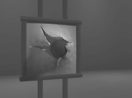
Graphicsmonitorsforthedisplayofthree-dimensionalsceneshavebeendevisedusingatechniquethatreflectsaCRTimagefromavibrating,flexiblemirror (Fig.14).Asthevarifocalmirrorvibrates,itchangesfocallength.ThesevibrationsaresynchronizedwiththedisplayofanobjectonaCRTsothateachpoint ontheobjectisreflectedfromthemirrorintoaspatialpositioncorresponding tothedistanceofthatpointfromaspecifiedviewinglocation.Thisallowsusto walkaroundanobjectorsceneandviewitfromdifferentsides.
Inadditiontodisplayingthree-dimensionalimages,thesesystemsare oftencapableofdisplayingtwo-dimensionalcross-sectional“slices”ofobjects selectedatdifferentdepths,suchasinmedicalapplicationstoanalyzedata fromultrasonographyandCATscandevices,ingeologicalapplicationsto analyzetopologicalandseismicdata,indesignapplicationsinvolvingsolid objects,andinthree-dimensionalsimulationsofsystems,suchasmoleculesand terrain.
Operationofathree-dimensional displaysystemusingavibratingmirror thatchangesfocallengthtomatchthe depthsofpointsinascene.
StereoscopicandVirtual-RealitySystems
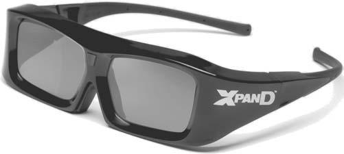
Glassesforviewingastereoscopic scenein3D.(CourtesyofXPAND,X6D USAInc.)
Anothertechniqueforrepresentingathree-dimensionalobjectistodisplay stereoscopicviewsoftheobject.Thismethoddoesnotproducetruethreedimensionalimages,butitdoesprovideathree-dimensionaleffectbypresenting adifferentviewtoeacheyeofanobserversothatscenesdoappeartohave depth.
Toobtainastereoscopicprojection,wemustobtaintwoviewsofascene generatedwithviewingdirectionsalongthelinesfromthepositionofeacheye (leftandright)tothescene.Wecanconstructthetwoviewsascomputer-generated sceneswithdifferentviewingpositions,orwecanuseastereocamerapairto photographanobjectorscene.Whenwesimultaneouslylookattheleftview withthelefteyeandtherightviewwiththerighteye,thetwoviewsmergeinto asingleimageandweperceiveascenewithdepth.
Onewaytoproduceastereoscopiceffectonarastersystemistodisplayeach ofthetwoviewsonalternaterefreshcycles.Thescreenisviewedthroughglasses, witheachlensdesignedtoactasarapidlyalternatingshutterthatissynchronized toblockoutoneoftheviews.Onesuchdesign(Figure15)usesliquid-crystal shuttersandaninfraredemitterthatsynchronizestheglasseswiththeviewson thescreen.
Stereoscopicviewingisalsoacomponentin virtual-reality systems,where userscanstepintoasceneandinteractwiththeenvironment.Aheadsetcontaininganopticalsystemtogeneratethestereoscopicviewscanbeusedinconjunctionwithinteractiveinputdevicestolocateandmanipulateobjectsinthescene. Asensingsystemintheheadsetkeepstrackoftheviewer’sposition,sothatthe frontandbackofobjectscanbeseenastheviewer“walksthrough”andinteractswiththedisplay.Anothermethodforcreatingavirtual-realityenvironment
FIGURE14
FIGURE15
Architectureofasimpleraster-graphics system.
istouseprojectorstogenerateascenewithinanarrangementofwalls,wherea viewerinteractswithavirtualdisplayusingstereoscopicglassesanddatagloves (Section4).
Lower-cost,interactivevirtual-realityenvironmentscanbesetupusinga graphicsmonitor,stereoscopicglasses,andahead-trackingdevice.Thetrackingdeviceisplacedabovethevideomonitorandisusedtorecordheadmovements,sothattheviewingpositionforascenecanbechangedasheadposition changes.
2 Raster-ScanSystems
Interactiveraster-graphicssystemstypicallyemployseveralprocessingunits.In additiontothecentralprocessingunit(CPU),aspecial-purposeprocessor,called the videocontroller or displaycontroller, isusedtocontroltheoperationofthe displaydevice.OrganizationofasimplerastersystemisshowninFigure16. Here,theframebuffercanbeanywhereinthesystemmemory,andthevideo controlleraccessestheframebuffertorefreshthescreen.Inadditiontothevideo controller,moresophisticatedrastersystemsemployotherprocessorsascoprocessorsandacceleratorstoimplementvariousgraphicsoperations.
VideoController
Figure17showsacommonlyusedorganizationforrastersystems.Afixedarea ofthesystemmemoryisreservedfortheframebuffer,andthevideocontrolleris givendirectaccesstotheframe-buffermemory.
Frame-bufferlocations,andthecorrespondingscreenpositions,arereferencedinCartesiancoordinates.Inanapplicationprogram,weusethecommands
FIGURE17
Architectureofarastersystemwitha fixedportionofthesystemmemory reservedfortheframebuffer.
FIGURE16
withinagraphicssoftwarepackagetosetcoordinatepositionsfordisplayed objectsrelativetotheoriginoftheCartesianreferenceframe.Often,thecoordinateoriginisreferencedatthelower-leftcornerofascreendisplayareabythe softwarecommands,althoughwecantypicallysettheoriginatanyconvenient locationforaparticularapplication.Figure18showsatwo-dimensionalCartesianreferenceframewiththeoriginatthelower-leftscreencorner.Thescreen surfaceisthenrepresentedasthefirstquadrantofatwo-dimensionalsystem, withpositive x valuesincreasingfromlefttorightandpositive y valuesincreasingfromthebottomofthescreentothetop.Pixelpositionsarethenassigned integer x valuesthatrangefrom0to xmax acrossthescreen,lefttoright,andinteger y valuesthatvaryfrom0to ymax ,bottomtotop.However,hardwareprocesses suchasscreenrefreshing,aswellassomesoftwaresystems,referencethepixel positionsfromthetop-leftcornerofthescreen.
InFigure19,thebasicrefreshoperationsofthevideocontrollerarediagrammed.Tworegistersareusedtostorethecoordinatevaluesforthescreen pixels.Initially,the x registerissetto0andthe y registerissettothevaluefor thetopscanline.Thecontentsoftheframebufferatthispixelpositionarethen retrievedandusedtosettheintensityoftheCRTbeam.Thenthe x registeris incrementedby1,andtheprocessisrepeatedforthenextpixelonthetopscan line.Thisprocedurecontinuesforeachpixelalongthetopscanline.Afterthe lastpixelonthetopscanlinehasbeenprocessed,the x registerisresetto0and the y registerissettothevalueforthenextscanlinedownfromthetopofthe screen.Pixelsalongthisscanlinearethenprocessedinturn,andtheprocedureis repeatedforeachsuccessivescanline.Aftercyclingthroughallpixelsalongthe bottomscanline,thevideocontrollerresetstheregisterstothefirstpixelposition onthetopscanlineandtherefreshprocessstartsover.
Sincethescreenmustberefreshedatarateofatleast60framespersecond, thesimpleprocedureillustratedinFigure19maynotbeaccommodatedby typicalRAMchipsifthecycletimeistooslow.Tospeeduppixelprocessing,
FIGURE18
ACartesianreferenceframewith originatthelower-leftcornerofa videomonitor.
FIGURE19 Basicvideo-controllerrefresh operations.
FIGURE20 Architectureofaraster-graphics systemwithadisplayprocessor.
videocontrollerscanretrievemultiplepixelvaluesfromtherefreshbufferon eachpass.Themultiplepixelintensitiesarethenstoredinaseparateregisterand usedtocontroltheCRTbeamintensityforagroupofadjacentpixels.Whenthat groupofpixelshasbeenprocessed,thenextblockofpixelvaluesisretrievedfrom theframebuffer.
Avideocontrollercanbedesignedtoperformanumberofotheroperations. Forvariousapplications,thevideocontrollercanretrievepixelvaluesfromdifferentmemoryareasondifferentrefreshcycles.Insomesystems,forexample, multipleframebuffersareoftenprovidedsothatonebuffercanbeusedfor refreshingwhilepixelvaluesarebeingloadedintotheotherbuffers.Thenthe currentrefreshbuffercanswitchroleswithoneoftheotherbuffers.Thisprovidesafastmechanismforgeneratingreal-timeanimations,forexample,since differentviewsofmovingobjectscanbesuccessivelyloadedintoabufferwithout interruptingarefreshcycle.Anothervideo-controllertaskisthetransformation ofblocksofpixels,sothatscreenareascanbeenlarged,reduced,ormovedfrom onelocationtoanotherduringtherefreshcycles.Inaddition,thevideocontroller oftencontainsalookuptable,sothatpixelvaluesintheframebufferareused toaccessthelookuptableinsteadofcontrollingtheCRTbeamintensitydirectly. Thisprovidesafastmethodforchangingscreenintensityvalues. Finally, some systemsaredesigned to allow the video controller to mix the frame-buffer image with an input image from a television camera or other input device.
Raster-ScanDisplayProcessor
Figure20showsonewaytoorganizethecomponentsofarastersystemthat containsaseparate displayprocessor, sometimesreferredtoasa graphicscontroller ora displaycoprocessor. Thepurposeofthedisplayprocessoristofree theCPUfromthegraphicschores.Inadditiontothesystemmemory,aseparate display-processormemoryareacanbeprovided.
Amajortaskofthedisplayprocessorisdigitizingapicturedefinitiongiven inanapplicationprogramintoasetofpixelvaluesforstorageintheframe buffer.Thisdigitizationprocessiscalled scanconversion. Graphicscommands specifyingstraightlinesandothergeometricobjectsarescanconvertedintoa setofdiscretepoints,correspondingtoscreenpixelpositions.Scanconverting astraight-linesegment,forexample,meansthatwehavetolocatethepixel positionsclosesttothelinepathandstorethecolorforeachpositionintheframe
buffer.Similarmethodsareusedforscanconvertingotherobjectsinapicture definition.Characterscanbedefinedwithrectangularpixelgrids,asin Figure21,ortheycanbedefinedwithoutlineshapes,asinFigure22.The arraysizeforcharactergridscanvaryfromabout5by7to9by12ormorefor higher-qualitydisplays.Acharactergridisdisplayedbysuperimposingtherectangulargridpatternintotheframebufferataspecifiedcoordinateposition.For charactersthataredefinedasoutlines,theshapesarescan-convertedintothe framebufferbylocatingthepixelpositionsclosesttotheoutline.
Displayprocessorsarealsodesignedtoperformanumberofadditionaloperations.Thesefunctionsincludegeneratingvariouslinestyles(dashed,dotted,or solid),displayingcolorareas,andapplyingtransformationstotheobjectsina scene.Also,displayprocessorsaretypicallydesignedtointerfacewithinteractive inputdevices,suchasamouse.
Inanefforttoreducememoryrequirementsinrastersystems,methodshave beendevisedfororganizingtheframebufferasalinkedlistandencodingthe colorinformation.Oneorganizationschemeistostoreeachscanlineasasetof numberpairs.Thefirstnumberineachpaircanbeareferencetoacolorvalue,and thesecondnumbercanspecifythenumberofadjacentpixelsonthescanlinethat aretobedisplayedinthatcolor.Thistechnique,called run-lengthencoding, can resultinaconsiderablesavinginstoragespaceifapictureistobeconstructed mostlywithlongrunsofasinglecoloreach.Asimilarapproachcanbetaken whenpixelcolorschangelinearly.Anotherapproachistoencodetherasterasa setofrectangularareas(cellencoding).Thedisadvantagesofencodingrunsare thatcolorchangesaredifficulttorecordandstoragerequirementsincreaseasthe lengthsoftherunsdecrease.Inaddition,itisdifficultforthedisplaycontrollerto processtherasterwhenmanyshortrunsareinvolved.Moreover,thesizeofthe framebufferisnolongeramajorconcern,becauseofsharpdeclinesinmemory costs.Nevertheless,encodingmethodscanbeusefulinthedigitalstorageand transmissionofpictureinformation.
3 GraphicsWorkstations andViewingSystems
Mostgraphicsmonitorstodayoperateasraster-scandisplays,andbothCRT andflat-panelsystemsareincommonuse.Graphicsworkstationsrangefrom smallgeneral-purposecomputersystemstomulti-monitorfacilities,oftenwith ultra-largeviewingscreens.Forapersonalcomputer,screenresolutionsvary fromabout640by480to1280by1024,anddiagonalscreenlengthsmeasurefrom 12inchestoover21inches.Mostgeneral-purposesystemsnowhaveconsiderablecolorcapabilities,andmanyarefull-colorsystems.Foradesktopworkstation specificallydesignedforgraphicsapplications,thescreenresolutioncanvaryfrom 1280by1024toabout1600by1200,withatypicalscreendiagonalof18inches ormore.Commercialworkstationscanalsobeobtainedwithavarietyofdevices forspecificapplications.
High-definitiongraphicssystems,withresolutionsupto2560by2048, arecommonlyusedinmedicalimaging,air-trafficcontrol,simulation,and CAD.Manyhigh-endgraphicsworkstationsalsoincludelargeviewingscreens, oftenwithspecializedfeatures.
Multi-paneldisplayscreensareusedinavarietyofapplicationsthatrequire “wall-sized”viewingareas.Thesesystemsaredesignedforpresentinggraphics displaysatmeetings,conferences,conventions,tradeshows,retailstores,museums,andpassengerterminals.Amulti-paneldisplaycanbeusedtoshowalarge
FIGURE21
Acharacterdefinedasarectangular gridofpixelpositions.
FIGURE22
Acharacterdefinedasanoutline shape.
viewofasinglesceneorseveralindividualimages.Eachpanelinthesystem displaysonesectionoftheoverallpicture.ColorPlate7showsa360 paneled viewingsystemintheNASAcontrol-towersimulator,whichisusedfortrainingandfortestingwaystosolveair-trafficandrunwayproblemsatairports. Largegraphicsdisplayscanalsobepresentedoncurvedviewingscreens.Alarge, curved-screensystemcanbeusefulforviewingbyagroupofpeoplestudyingaparticulargraphicsapplication,suchastheexampleinColorPlate8.A controlcenter,featuringabatteryofstandardmonitors,allowsanoperatorto viewsectionsofthelargedisplayandtocontroltheaudio,video,lighting,and projectionsystemsusingatouch-screenmenu.Thesystemprojectorsprovidea seamless,multichanneldisplaythatincludesedgeblending,distortioncorrection, andcolorbalancing.Andasurround-soundsystemisusedtoprovidetheaudio environment.
4 InputDevices
Graphicsworkstationscanmakeuseofvariousdevicesfordatainput.Mostsystemshaveakeyboardandoneormoreadditionaldevicesspecificallydesignedfor interactiveinput.Theseincludeamouse,trackball,spaceball,andjoystick.Some otherinputdevicesusedinparticularapplicationsaredigitizers,dials,button boxes,datagloves,touchpanels,imagescanners,andvoicesystems.
Keyboards,ButtonBoxes,andDials
Analphanumeric keyboard onagraphicssystemisusedprimarilyasadevicefor enteringtextstrings,issuingcertaincommands,andselectingmenuoptions.The keyboardisanefficientdeviceforinputtingsuchnongraphicdataaspicturelabels associatedwithagraphicsdisplay.Keyboardscanalsobeprovidedwithfeatures tofacilitateentryofscreencoordinates,menuselections,orgraphicsfunctions.
Cursor-controlkeysandfunctionkeysarecommonfeaturesongeneralpurposekeyboards.Functionkeysallowuserstoselectfrequentlyaccessedoperationswithasinglekeystroke,andcursor-controlkeysareconvenientforselecting adisplayedobjectoralocationbypositioningthescreencursor.Akeyboard canalsocontainothertypesofcursor-positioningdevices,suchasatrackballor joystick,alongwithanumerickeypadforfastentryofnumericdata.Inadditiontothesefeatures,somekeyboardshaveanergonomicdesignthatprovides adjustmentsforrelievingoperatorfatigue.
Forspecializedtasks,inputtoagraphicsapplicationmaycomefromasetof buttons,dials,orswitchesthatselectdatavaluesorcustomizedgraphicsoperations.Buttonsandswitchesareoftenusedtoinputpredefinedfunctions,and dialsarecommondevicesforenteringscalarvalues.Numericalvalueswithin somedefinedrangeareselectedforinputwithdialrotations.Apotentiometer isusedtomeasuredialrotation,whichisthenconvertedtothecorresponding numericalvalue.
MouseDevices
A mouse isasmallhandheldunitthatisusuallymovedaroundonaflatsurface topositionthescreencursor.Oneormorebuttonsonthetopofthemouseprovide amechanismforcommunicatingselectioninformationtothecomputer;wheels orrollersonthebottomofthemousecanbeusedtorecordtheamountand directionofmovement.Anothermethodfordetectingmousemotioniswithan opticalsensor.Forsomeopticalsystems,themouseismovedoveraspecialmouse padthathasagridofhorizontalandverticallines.Theopticalsensordetects
FIGURE23
Awirelesscomputermousedesignedwithmanyuser-programmablecontrols.
(CourtesyofLogitech® )
movementacrossthelinesinthegrid.Otheropticalmousesystemscanoperate onanysurface.Somemousesystemsarecordless,communicatingwithcomputer processorsusingdigitalradiotechnology.
Sinceamousecanbepickedupandputdownatanotherpositionwithout changeincursormovement,itisusedformakingrelativechangesintheposition ofthescreencursor.One,two,three,orfourbuttonsareincludedonthetopof themouseforsignalingtheexecutionofoperations,suchasrecordingcursor positionorinvokingafunction.Mostgeneral-purposegraphicssystemsnow includeamouseandakeyboardastheprimaryinputdevices.
Additionalfeaturescanbeincludedinthebasicmousedesigntoincrease thenumberofallowableinputparametersandthefunctionalityofthemouse. TheLogitechG700wirelessgamingmouseinFigure23features13separatelyprogrammablecontrolinputs.Eachinputcanbeconfiguredtoperformawide rangeofactions,fromtraditionalsingle-clickinputstomacrooperationscontainingmultiplekeystrongs,mouseevents,andpre-programmeddelaysbetween operations.Thelaser-basedopticalsensorcanbeconfiguredtocontrolthedegree ofsensitivitytomotion,allowingthemousetobeusedinsituationsrequiringdifferentlevelsofcontrolovercursormovement.Inaddition,themousecanholdup tofivedifferentconfigurationprofilestoallowtheconfigurationtobeswitched easilywhenchangingapplications.
TrackballsandSpaceballs
A trackball isaballdevicethatcanberotatedwiththefingersorpalmofthehand toproducescreen-cursormovement.Potentiometers,connectedtotheball,measuretheamountanddirectionofrotation.Laptopkeyboardsareoftenequipped withatrackballtoeliminatetheextraspacerequiredbyamouse.Atrackballalso canbemountedonotherdevices,oritcanbeobtainedasaseparateadd-onunit thatcontainstwoorthreecontrolbuttons.
Anextensionofthetwo-dimensionaltrackballconceptisthe spaceball, which providessixdegreesoffreedom.Unlikethetrackball,aspaceballdoesnotactually move.Straingaugesmeasuretheamountofpressureappliedtothespaceballto provideinputforspatialpositioningandorientationastheballispushedorpulled invariousdirections.Spaceballsareusedforthree-dimensionalpositioningand selectionoperationsinvirtual-realitysystems,modeling,animation,CAD,and otherapplications.
Joysticks
Anotherpositioningdeviceisthe joystick, whichconsistsofasmall,verticallever (calledthestick)mountedonabase.Weusethejoysticktosteerthescreencursor around.Mostjoysticksselectscreenpositionswithactualstickmovement;others