11 minute read
Chapter 1 • Installing the Raspberry Pi 4
1.1 Hardware description
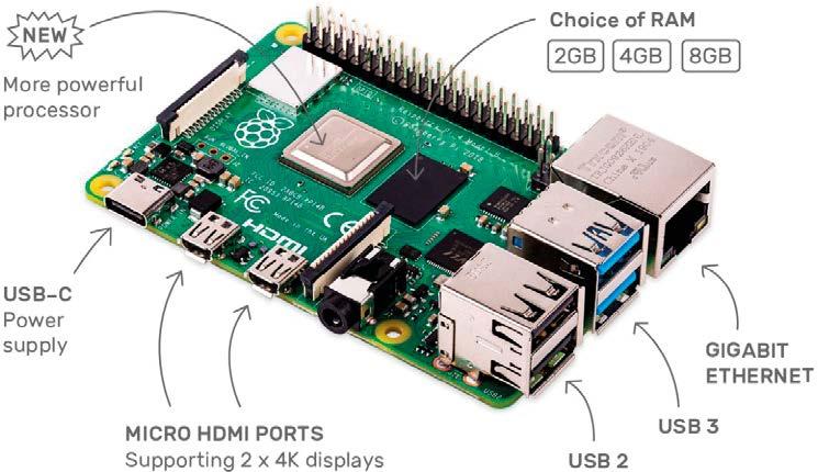
The Raspberry Pi is now a well-known minicomputer, which, thanks of its low price, is widely used by hobbyists and industrial companies alike.
Figure 1.1: The Raspberry Pi 4.
The RPi 4 has enough interfaces to be used as a PLC. In addition to standard interfaces such as HDMI, USB, Ethernet, and audio, it has a 40-pin GPIO connector strip to connect to the outside world. Relays, buttons, switches, etc. can be connected to this connector via suitable interfaces. Hardware aspects are not discussed further for now — the Raspberry Pi website is host to several detailed tutorials about this minicomputer.
If you are looking for a more compact solution, you could also use the Raspberry Pi Zero W. After a first test by the author, everything turned out to work fine. If you can tolerate the lengthy installation process which takes several hours, the "W" is a good, low-priced alternative to the Raspberry Pi 4.

Figure 1.2: Raspberry Pi Zero W.
To use the Raspberry Pi as a PLC, first install the operating system, which can be found on the Raspberry.org website. Link: Raspberry Pi OS – Raspberry Pi.
1.2 Installing the operating system
Download the Raspberry Pi Imager here. This is a simple and quick way to install the operating system on a Micro SD card. There is also a video about this on YouTube. Link:
https://www.youtube.com/watch?v=J024soVgEeM
After downloading, change to this directory and start the imager.
Link: https://downloads.raspberrypi.org/imager/imager_1.5.exe
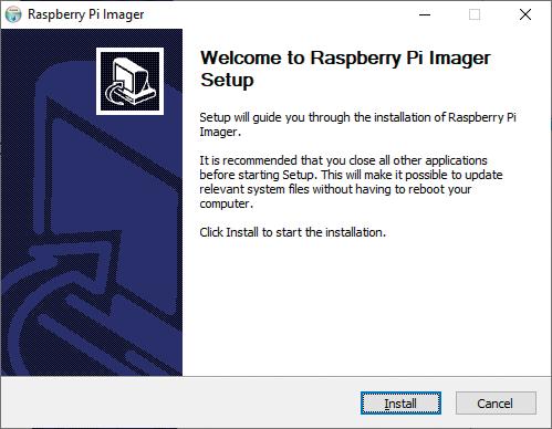
Figure 1.3: Raspberry Pi Imager launched.
After clicking on "Install", the installation of the Imager program will commence. The Imager is used to install our Micro SD card.
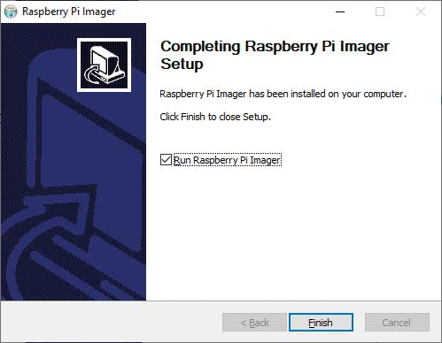
Figure 1.4: Raspberry Pi Imager Setup.
With a click on the checkbox "Run Raspberry Pi Imager" the program launches after successful installation.
Select the Raspberry Pi OS (32-bit) as the operating system. Then select the drive where the Micro SD card is connected. Here, that's drive G:
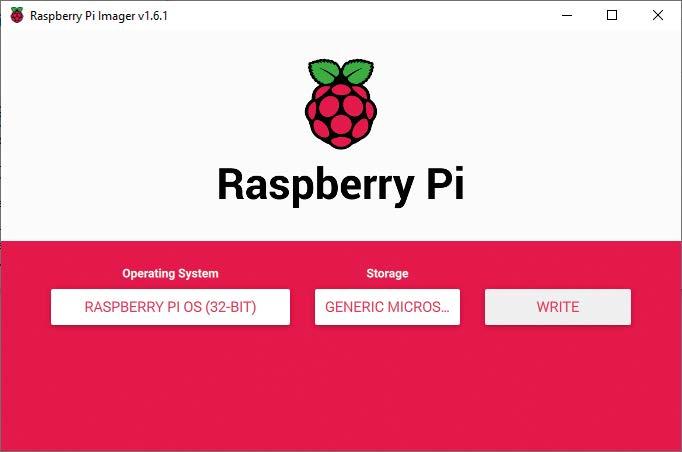
Figure 1.5: Raspberry Pi Imager OS selection.
Click the "Write" button to launch the installation.
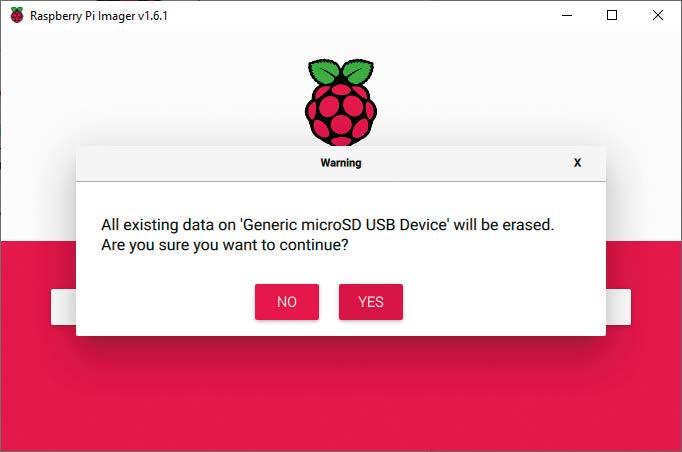
Figure 1.6: Raspberry Pi Imager startup.
Confirm the security prompt with "YES".
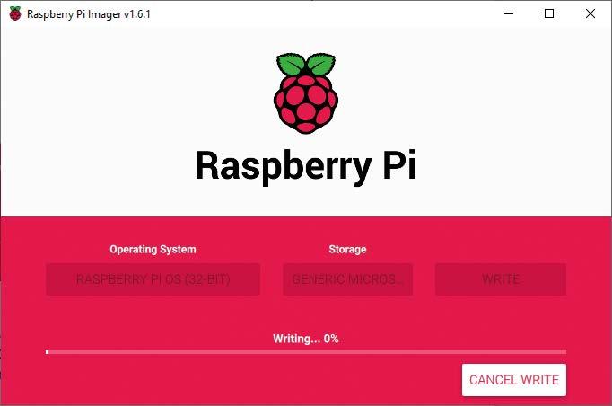
Figure 1.7: Writing to the SD card using the Raspberry Pi Imager.
Now the operating system is downloaded and written to the micro SD card. This can take about 30 minutes, depending on the computer. After the signal that writing to the card has been completed, exit the Imager with "CONTINUE".
Documentation for installation and usage can also be found here. Link: Raspberry Pi Documentation
The next step is to set up the Raspberry Pi. Insert the programmed Micro SD card into the Raspberry Pi. Next, plug in a monitor, keyboard, and mouse for the first setup of the Raspberry Pi. Now connect the 5 V power supply to the Raspberry Pi. The operating system should boot.
After the initial start, the operating system prompts for the country and time zone selection. Enter your details here. Now the settings are installed. After this, the password is requested. The default username is "pi", and the password is "raspberry".
If there is no Ethernet connection, set up the network access via WLAN. In the upper right corner between the Bluetooth and the speaker icon, click on the WLAN icon. Select your WLAN network and enter the access code. After a few seconds, the connection to the home or office WLAN is established. Continue with the installation of the updates. This can take several minutes. After this, a reboot is performed. When you click on the WLAN icon, you will also see the IP address. Make a note of it for later use with VNC and the PLC software, which is yet to be installed. Here, the IP is: 192.168.178.89.
Later, when the Raspberry Pi is used as a PLC, it will be easier to access it through VNC Viewer.
Follow: Menu Settings Raspberry Pi Configuration. Next, under Interfaces, the VNC Viewer can be enabled.
1.3 Installing the VNC Viewer
VNC is a graphical desktop sharing system allowing you to remotely control the desktop interface of a computer, in this case the Raspberry Pi (VNC Server) from another computer or mobile device using VNC Viewer (Client). VNC Viewer transmits keyboard, mouse, or touch events to VNC Server and in return receives information for screen updates. This can be downloaded and installed on a PC for now.
Link: https://www.realvnc.com/en/connect/download/viewer/.
The appropriate viewer can be downloaded at this url. We're using the latest version for Windows 10, but an Android version is also available.
After downloading, start the installation.
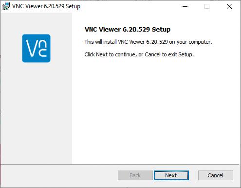
Figure 1.8: VNC Viewer installation.
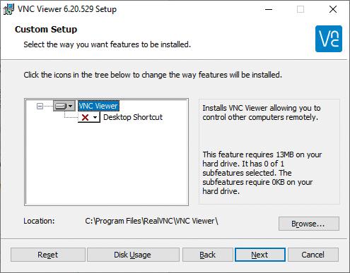
Figure 1.9: VNC Viewer installation.
Continue the installation by clicking on "Next". Click on "Install". This will launch the installation of the Viewer.
Start VNC Viewer and connect to the Raspberry Pi.
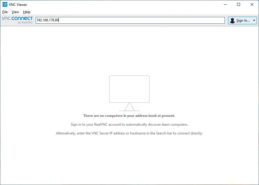
Figure 1.10: VNC Viewer start menu.
Under "File", and then "New Connection", enter the access data from your Raspberry Pi.
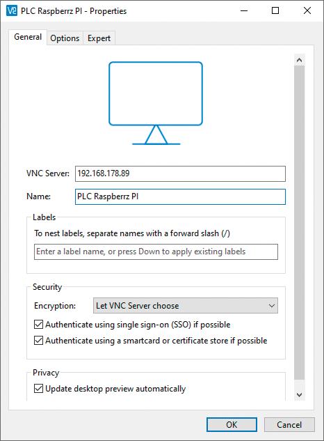
Figure 1.11 VNC Viewer configuration.
Enter the IP address and a suitable name. Afterwards, confirm the "Properties", "General" window with "OK".
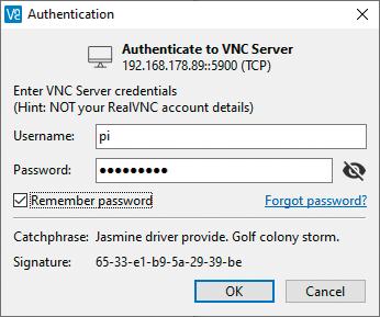
Figure 1.12: VNC Viewer credentials
Enter the username "pi" and password "raspberry" and confirm with "OK". Shortly, the Raspberry Pi desktop will appear on your PC screen.

Figure 1.13 Raspberry Pi OS Desktop.
1.4 Installing the File Transfer Software WinSCP
WinSCP is an open-source SFTP and FTP client for Windows, needed to transfer files between a PC and Raspberry Pi.
To get access, enable SSH on the Raspberry Pi under Settings Raspberry Pi Configuration Interfaces.
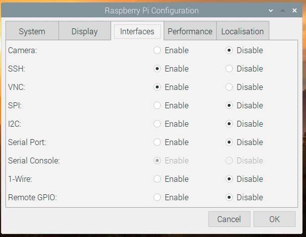
Figure 1.14: SSH configuration.
Firstly, download and save the installer.
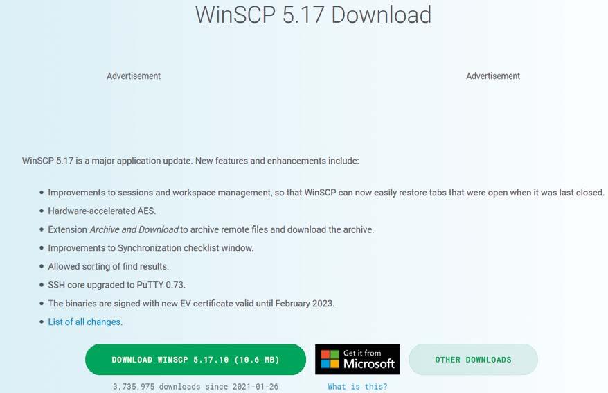
Figure 1.15: WinSCP Download.
Now change to the download directory and start the installation.
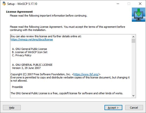
Figure 1.16: WinSCP installation
Accept the license agreement by clicking "Accept".
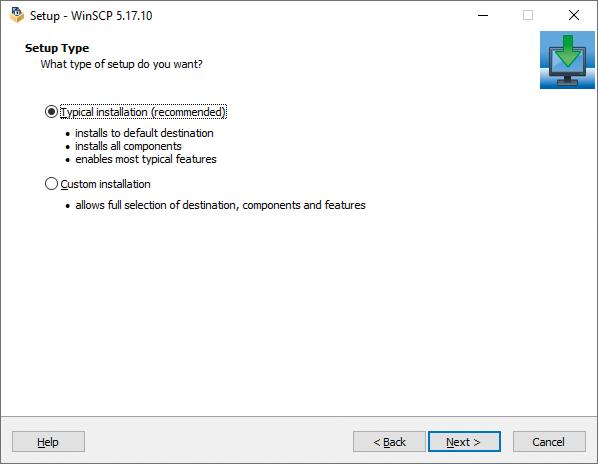
Figure 1.17: WinSCP installation.
Confirm with "Next".
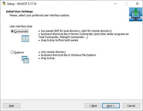
Figure 1.18: WinSCP installation.
Select the user interface "Commander", go to "Next" and confirm with "Install".
Start WinSCP and set up a new connection with the Raspberry Pi's IP address. As an example, the IP address was 192.168.178.89 with access data.
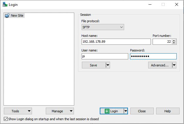
Figure 1.19: WinSCP credentials configuration.
Log in and save the connection destination.
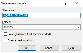
Figure 1.20: WinSCP configuration of directories.
You can now access the file directories of the Raspberry Pi.
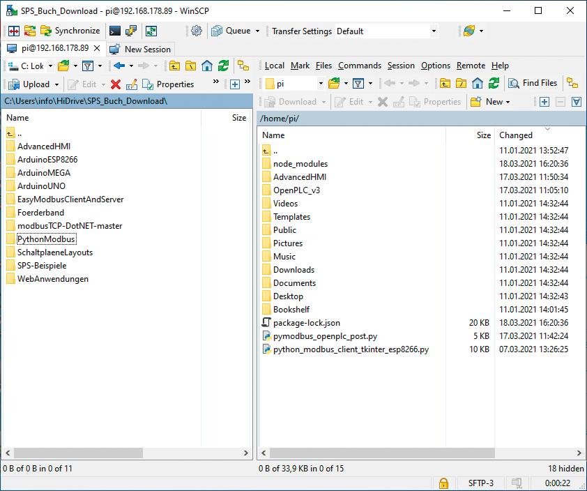
Figure 1.21: WinSCP in action
1.5 Installing the openplcproject runtime
With your PLC computer set up so far, the next important step is to install the Open PLC Runtime from the Open PLC Project website.
Link: https://www.openplcproject.com/runtime/raspberry-pi/
The easiest way to copy OpenPLC files to your Raspberry Pi is to use Git. Normally, Git is preinstalled on Raspbian. If for some reason you don't have Git installed on your system, you can fix that by typing some commands. To be able to do that, open a Terminal box either on the Raspberry Pi or via the VNC viewer and enter the following command:
sudo apt-get install git
and confirm with "Enter".
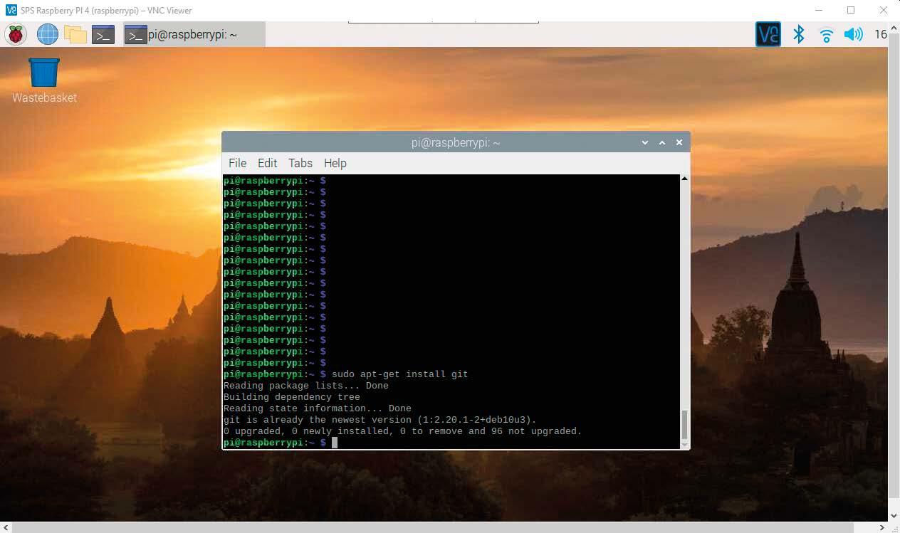
Figure 1.22: Install GIT.
For the installation of the OpenPLC Runtime (PLC operating system) you need the following commands:
git clone https://github.com/thiagoralves/OpenPLC_v3.git cd OpenPLC_v3 ./install.sh rpi
These can also be copied and pasted into the terminal window.
On the PC, copy the command to the clipboard and paste it on the Raspberry Pi in the Terminal window with the right-hand mouse button.
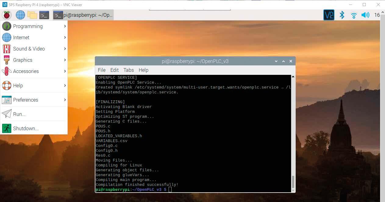
Figure 1.23: Installing OpenPLC Runtime.
This process takes some time. After the installation is finished, you should restart the Raspberry Pi.
The Open PLC Runtime has an integrated web server allowing you to configure OpenPLC and upload new programs. Subsequently, these can be started on the Raspberry Pi. This web server can be accessed by opening a web browser on the PC and entering the IP address of the Raspberry Pi through port 8080. For example, if your Raspberry Pi is at IP 192.168.178.89 in your network, you need to enter the following address in your browser:
192.168.178.89:8080
Of course, the web page can also be accessed on the Raspberry Pi with the web browser. Just enter "localhost:8080" in the URL line to get to the OpenPLC Runtime page.

Figure 1.24: OpenPLC Runtime web interface.
The default username and password are both: "openplc". These credentials can be changed after login.
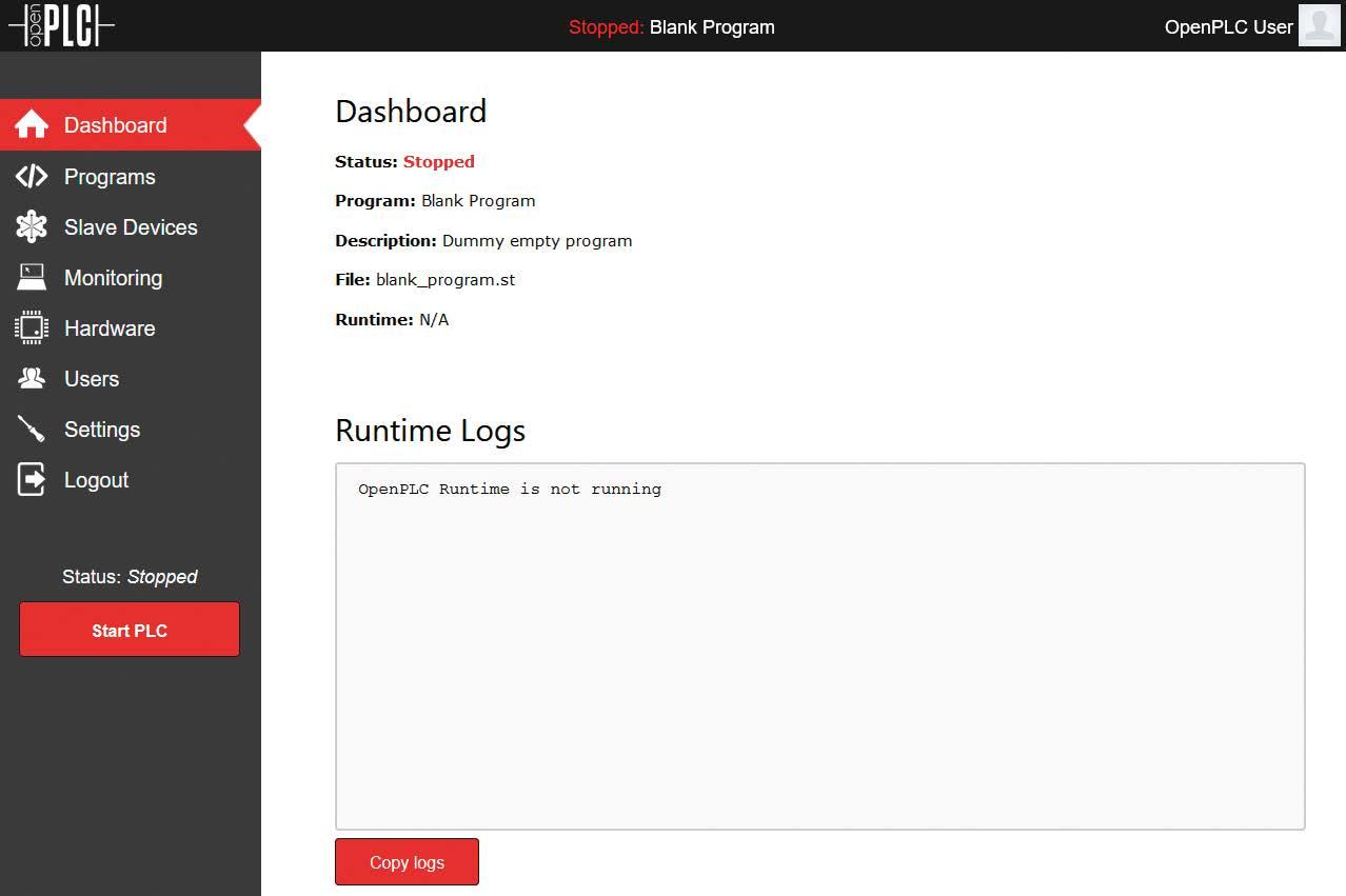
Figure 1.25: OpenPLC Runtime Dashboard.
After a successful login, the start menu pops up. Now various important settings for the hardware can be made. Our own PLC programs are also uploaded and started here. Configuration of external modules is also possible as well as monitoring of the running program.
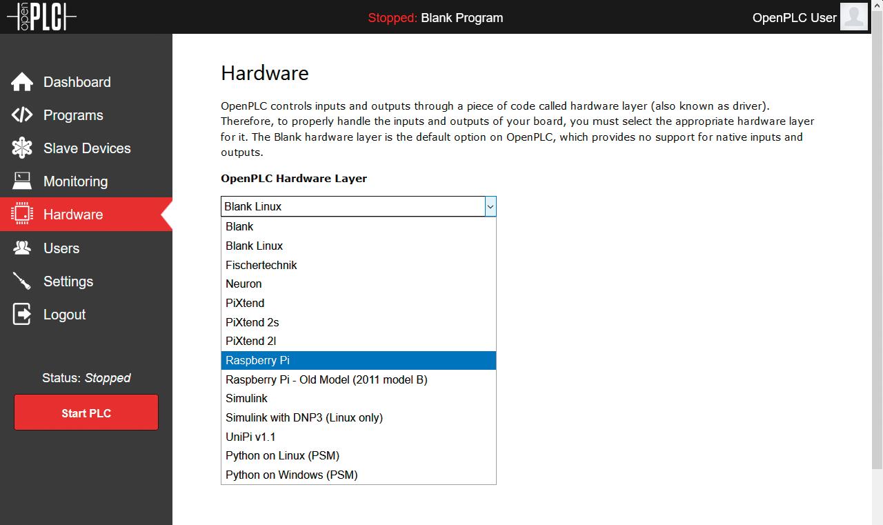
Figure 1.26: OpenPLC runtime hardware selection.
This is where the extensive selection takes place of the hardware running the Open PLC Runtime. Here, choose the Raspberry Pi. Save the setting with "Save Changes".
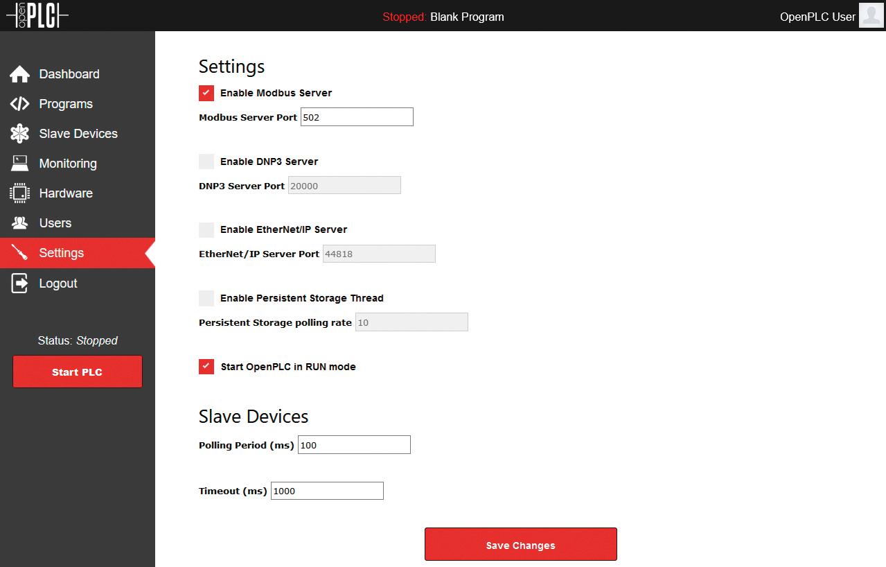
Figure 1.27: OpenPLC Runtime settings.
DNP3 and Ethernet/IP do not need to be selected for the time being, since you do not use these field buses. We leave the Modbus server installed as it's needed later for visualization using the AdvancedHMI software.
In case the Raspberry Pi should run the last program after a reboot, you can click on Settings Start OpenPLC in RUN Mode. Now click "Save Changes" and the installation is finished.
For an initial test, use the PLC program "PLC sample AWL running light", which can be found in the download area. To test drive the PLC program, transfer it from the PC to the new Raspberry Pi PLC by way of the web interface.
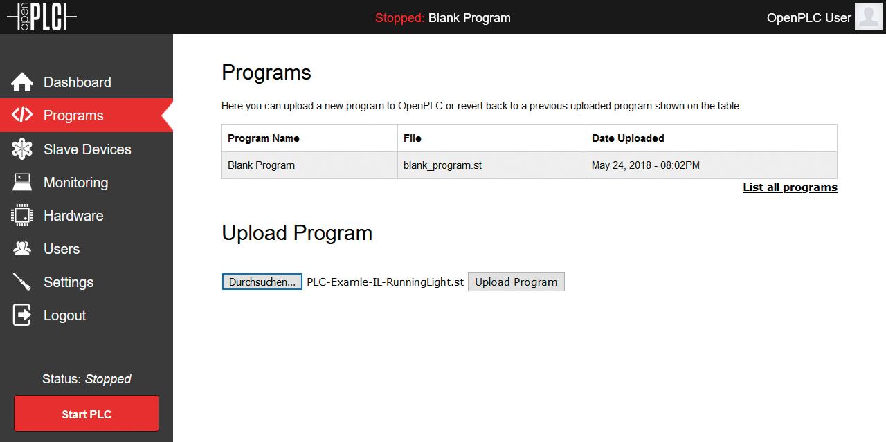
Figure 1.28: OpenPLC PLC program upload.
For this, click on "Browse" for the file dialog, select the ST file from your PLC project, and confirm with "Open".
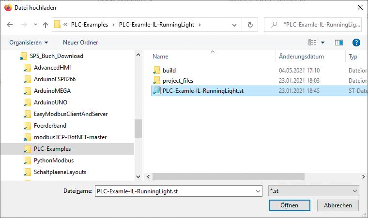
Figure 1.29: Select your OpenPLC ST file.
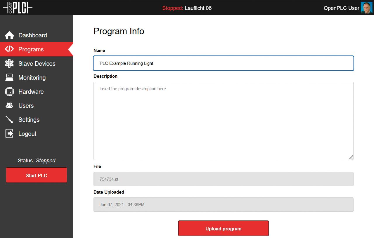
Figure 1.30: The OpenPLC PLC ST-Program upload process.
Now enter a name at the top under "Name". Here it's "PLC Example Running Light" so that the Upload button is enabled. Under "Description" a description of the program function and possibly a version number, can be entered.

Figure 1.31: Compiling ST program into C.
Now the ST program gets compiled into a C program for the Raspberry Pi. After that it can be started. Click on "Go to Dashboard" and change to the main menu. By clicking on "Start PLC", the program kicks off.
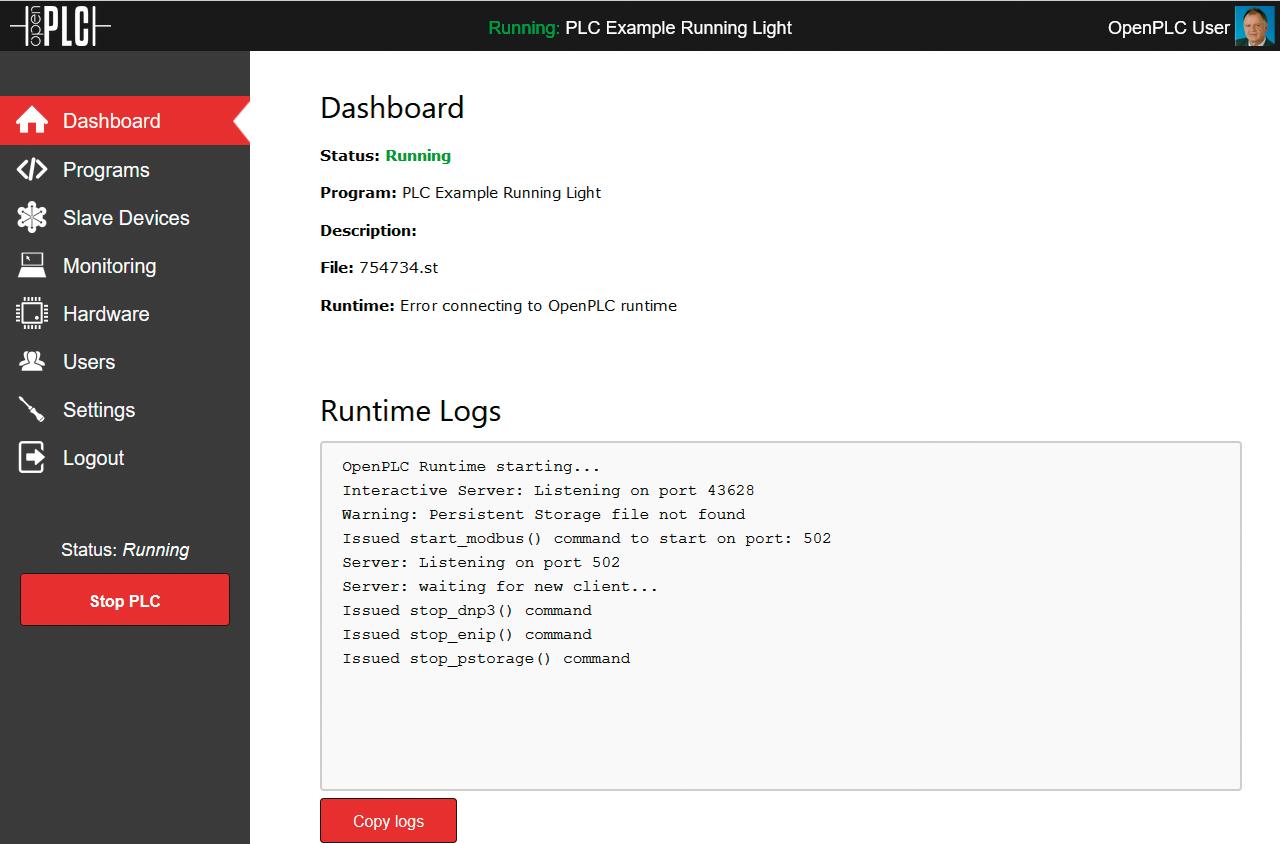
Figure 1.32: Dashboard Runtime Los.
Now three LEDs at the output pins %QX0.0, %QX0.1 and %QX0.2 should light up one after the other. You should also be able to observe this under "Monitoring".
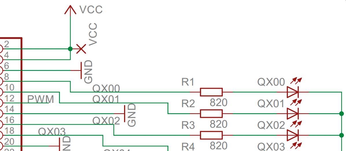
Figure 1.33: Connecting the LEDs
The complete schematic of the test board can be found in the Appendix.
If this test does not work, it's probably because of the "WiringPI" library this is responsible for accessing the GPIO pins. A likely solution to the problem is to install an up to date, Raspberry Pi 4-adapted, version. To do so, halt the running PLC program with the button "Stop PLC".
Next, in the terminal window enter the following commands for an update:
cd /tmp wget https://project-downloads.drogon.net/wiringpi-latest.deb sudo dpkg -i wiringpi-latest.deb
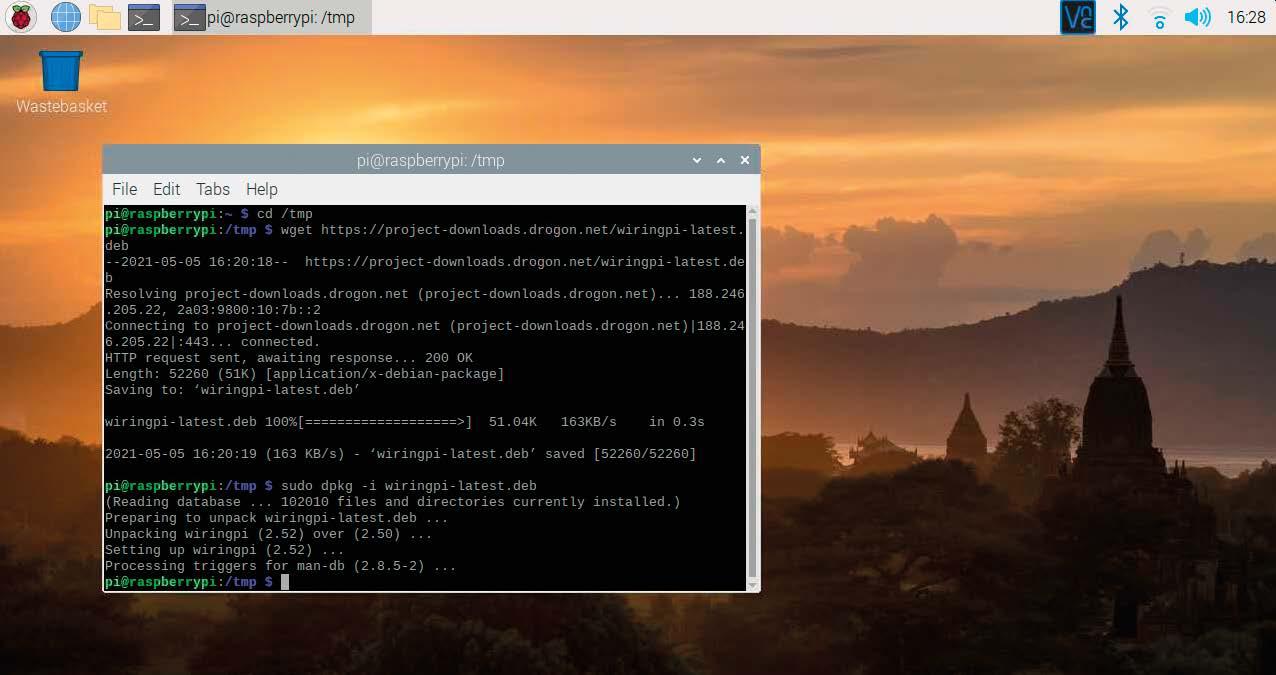
Figure 1.34: Install WiringPI library.
After that, the installation can be tested. The version 2.52 should be displayed.
gpio –v
It should display
gpio version: 2.52 Copyright (c) 2012-2018 Gordon Henderson This is free software with ABSOLUTELY NO WARRANTY. For details type: gpio -warranty
Raspberry Pi Details: Type: Pi 4B, Revision: 01, Memory: 2048MB, Maker: Sony * Device tree is enabled. *--> Raspberry Pi 4 Model B Rev 1.1 * This Raspberry Pi supports user-level GPIO access.
This completes the installation, and the PLC program is ready for starting. Now the LEDs should light up one after the other.
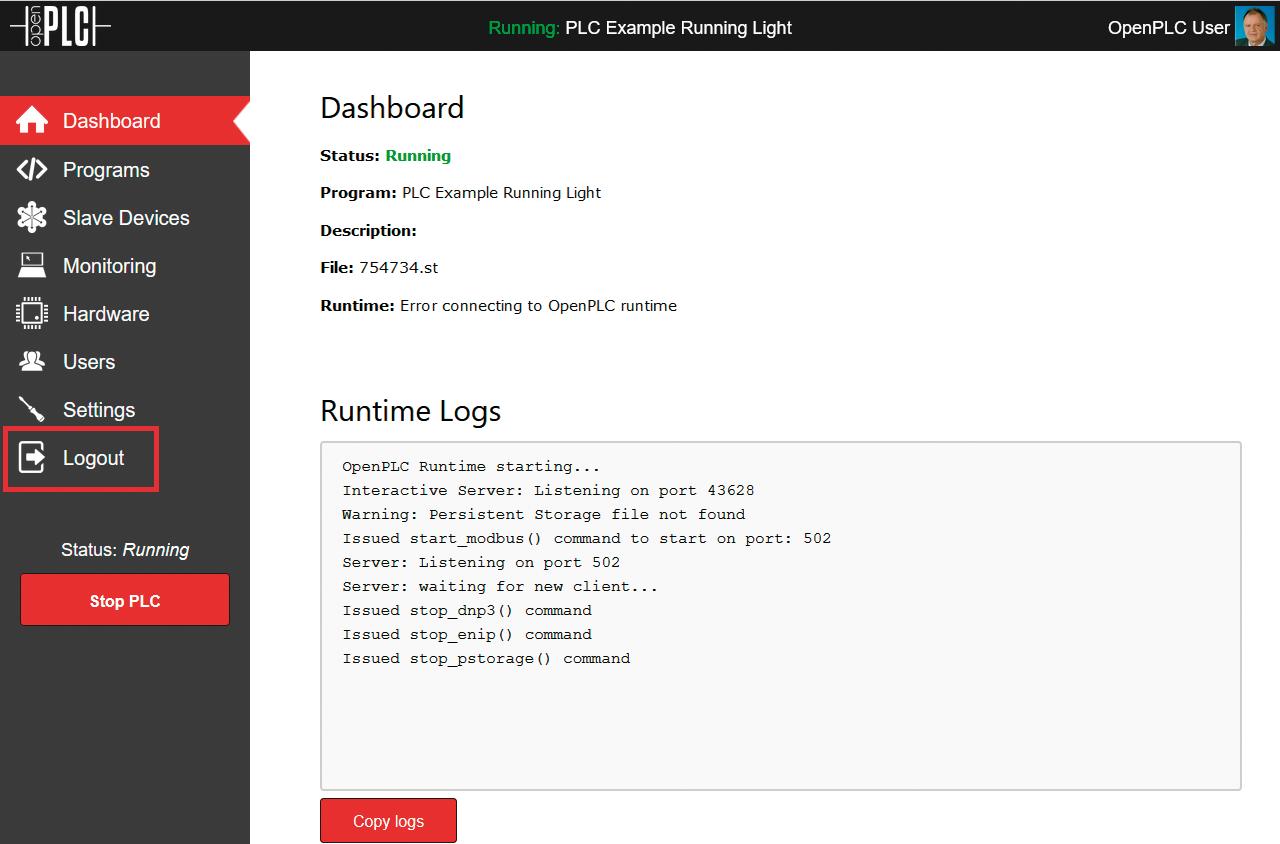
Figure 1.35: Logout from the OpenPLC PLC program.
Now you can exit and sign out of the Raspberry Pi by clicking on "Logout".
The next Chapter covers installing the editor on your PC and writing your first program.


