15 minute read
Chapter 1 • Automotive Bus Systems
1.1 Overview
Today's vehicles are complex machines incorporating mechanical and electronic parts. The number of electronic components used in vehicles has rapidly increased in recent years. As a result of the increase in safety, comfort, and performance requirements, we see many more electronic components being added to modern vehicles. Henceforth, there has been an increasing demand to connect these electronic components in such a way that they can communicate with each other reliably, safely, and in real time.
In the past, electronic units used to be connected in a complex way, with hundreds of wires running to distinct parts of a vehicle. Consequently, it was difficult to trace an electronic fault. There was no coordination between various parts of the electronics, as each electronic part was controlled independently of the others. Maintenance and repair of the vehicle electronics were extremely difficult, as in many cases it was not easy to locate and change a faulty component.
Passenger safety has also become one of the most important considerations in today's vehicles. In the past decade, safety equipment has evolved and moved from physical to electronic assisted safety, starting with braking and type technology, through collision protection and airbags, and most recently, on to safety-related driver assistance systems. The latest modern vehicles are smart and intelligent machines and are equipped with many sensors that can evaluate the surroundings and display useful and safety-related information to drivers. These sensors form intelligent local networks together with actuators, displays, and fast digital processors, such as high-speed purpose-built microcontrollers.
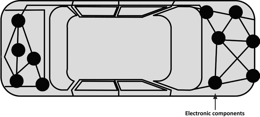
Figure 1.1 shows a traditional old-style vehicle electronic system with sensors and actuators interconnected to each other in a complex manner. One of the major problems in this type of design is maintenance. The wiring was so complex that it was nearly impossible to trace and rectify faults.
As the complexity of vehicle electronics has increased, it has become difficult for manufacturers to design safe and reliable electronic systems based on old traditional methods. Current requirements cannot be obtained using a simple electronic control unit. The solution is to interconnect the various electronic modules with a high-performance network. This is why it has become necessary to design a network-based electronic system where electronic modules can easily be attached to a network and then controlled from a central, intelligent unit (e.g., Engine Control Unit). The result of this is an "intelligent" car where many sensors and actuators are used to sense the environment and perform multiple functions. An example is the automatic turning on of headlights when it becomes dark or when the car goes through a tunnel. Another example is the automatic operation of windscreen wipers when the rain begins, and so on.
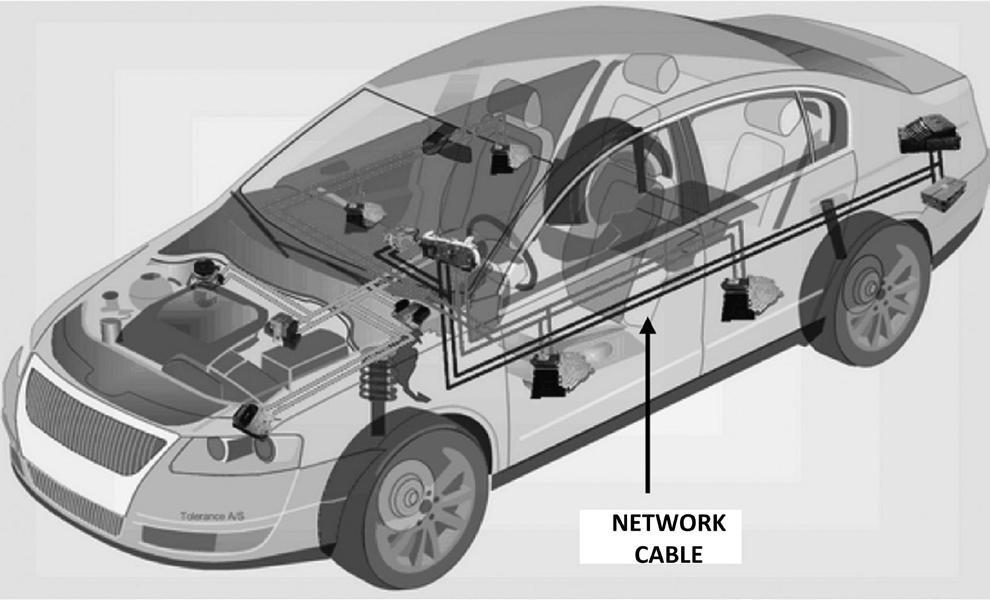
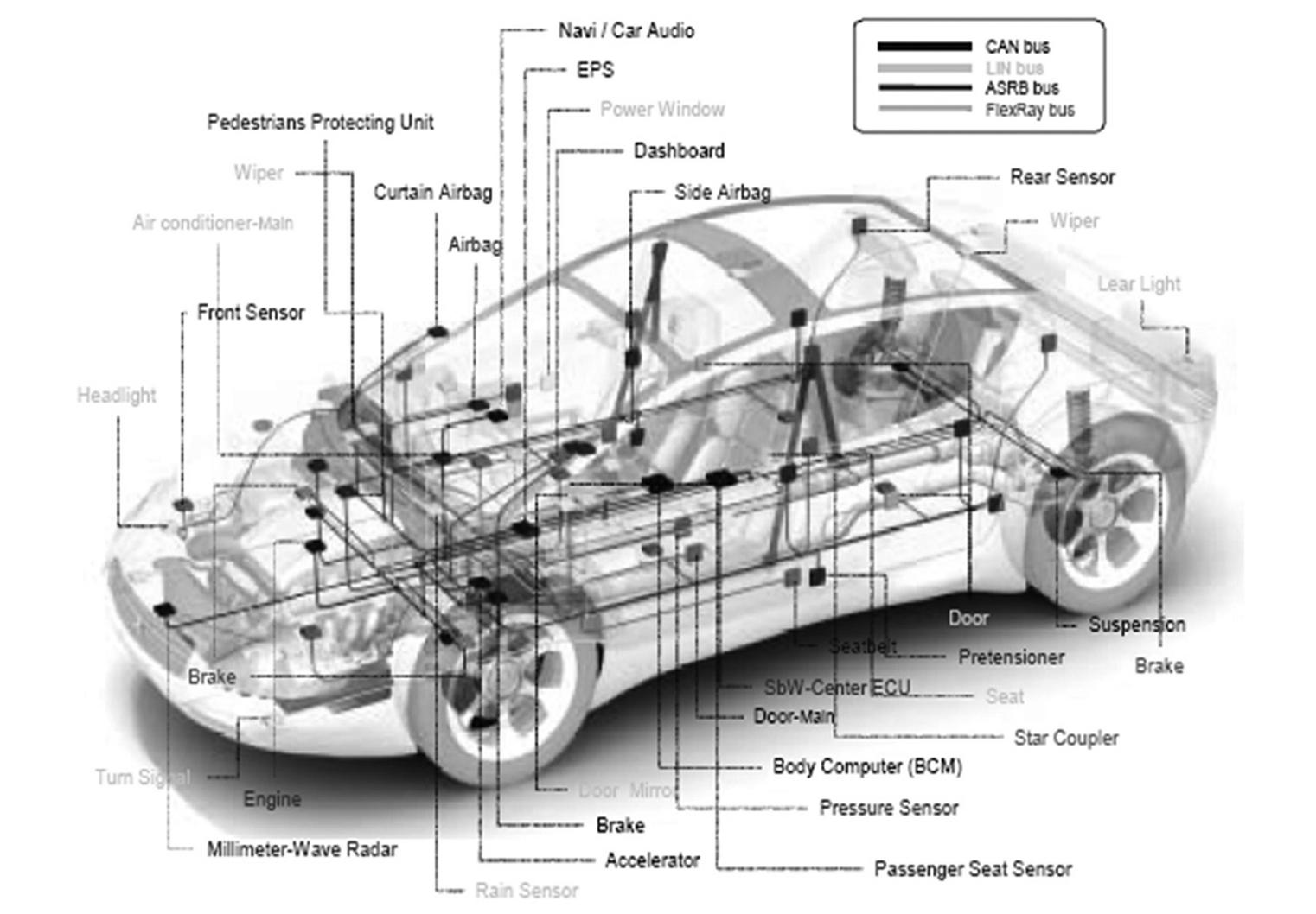
One of the advantages of a network-based vehicle electronic system is that it is relatively easy to trace and detect a faulty module. In addition, the wiring is a lot simpler and easier to maintain. For example, by communicating with the central intelligent controller unit, one can tell whether or not the overall electronics system is healthy, and if not, the faulty modules can easily be detected. A networked system also allows the various modules on the bus to communicate with each other and exchange information if required. For example, the intelligence controller unit can receive the engine temperature value from the temperature sensor module. This temperature can then be displayed on an electronic dashboard. Should the temperature be too high, appropriate messages can be sent to the responsible parts of the engine and corrective measures can easily be taken. Figure 1.2 shows a modern vehicle where an electronic network system is used to interconnect and control the electronic modules.
This chapter provides an overview of the most important vehicle network systems currently used in vehicles. Moreover, it provides a table to compare the advantages and disadvantages of each system.
1.2 Vehicle network systems
Vehicle network systems (or networks) were classified in 1994 by the Society of Automotive Engineers (SAE). According to this classification, bus systems were classified based on their bandwidth (i.e., data rate) and functions of the network system. The classification divides bus networks into four: Class A, Class B, Class C, and Class D.
Class A networks are low-speed, low-cost networks with data rates of less than 10 kbps. These systems are mainly used in the body of the car.
Class B networks operate between 10 and 125 kbps and are used for information exchange, e.g., instrument cluster, vehicle speed, and so on.
Class C networks operate between 125 and 1 Mbps and are used in a wide range of applications, such as engine control.
Class D networks operate above 1 Mbps, and they are mainly used in telematics applications.
There are many automotive network systems (or bus systems, since the vehicle networks are in the form of bus wires), some developed by vehicle manufacturers on their own, and some developed jointly with semiconductor manufacturers. Popular vehicle network systems include:
• CAN bus
• LIN bus
• FlexRay
• MOST
• Byteflight
• DSI bus
• Intellibus
• SAE J1850
• BST bus
• NML bus
• And others…
In this section, we shall be looking at the brief details of the most commonly used automotive network systems listed below, and concentrate on the CAN bus, which is the topic of this book.
• LIN bus
• FlexRay
• MOST
• Byteflight
• Intellibus
• CAN bus
1.2.1 LIN bus
The Local Interconnect or "LIN" bus is a low-cost bus operating at 20 kbps that has been developed to create a standard for low-cost, low-end communication in automotive electronics. LIN fits in the low end of the automotive network systems, thus making it cost-effective. This bus is mainly used for non-important body/comfort functions. LIN is a single-wire, single-master/multiple-slave type bus system where the vehicle chassis is used as the return path. In a typical application, the master broadcasts a message with a message header, asking for data, and the slave that has the correct message header sends the requested data including a checksum for error checking. Typical LIN bus appli- cations include the control of small motors for wipers, sunroof control, heating control, rain sensor control, steering wheel, seats, doors, etc. where high bandwidth is not required. The LIN bus is used in applications where the implementation of CAN bus would be too expensive. The initial LIN specification was defined by a consortium consisting of BMW, Audi, Volvo, VW, Motorola, Volcano, and DaimlerChrysler. The LIN bus is based on the Serial Communications Interface (UART) with 8-bit data.
1.2.2 FlexRay
As the demand for improved safety, increased performance, and enhanced comfort rises, then the need for more complex and more sophisticated electronic vehicle network systems arises. FlexRay was initially developed by BMW and Daimler Chrysler in 1999 as a fast, efficient, and error-free automotive bus system. FlexRay is suited to real-time, high-speed applications as it supports a bandwidth of up to 10 Mbps. Both electrical and optical transmission mediums can be used. FlexRay supports single and dual-channel configurations, with the dual channel offering enhanced fault-tolerance and increased bandwidth. Considered to be the next step beyond LIN and CAN, it is mainly used in safety-critical applications and in real-time high-speed engine control. Some application areas of FlexRay are: engine control, ABS, transmission control, break control, suspension control, etc.
1.2.3 MOST
The Media Oriented Systems Transport (MOST) bus is mainly used in automotive telemetric and multimedia applications, such as audio control, video, navigation, communication, and so on. Modern vehicle systems include multimedia devices such as DVD/CD players, TVs, navigation systems, graphics displays, and mobile computing which require very high data transfer rates. This is achieved using the MOST network. The original MOST network was developed by BMW and DaimlerChrysler in 1998.
MOST supports a maximum of 64 devices on the bus with very high bandwidth. Typical data rates are 28.8 Mbps synchronous, and 14.4 Mbps asynchronous. Up to 50 Mbps and even 150 Mbps are currently under development. An optical medium is used for data transmission that is free of any electromagnetic radiation or interference.
1.2.4 Byteflight
Byteflight was developed by BMW and offers 10 Mbps bandwidth. Byteflight is mainly used in safety-related networks, such as automotive and avionic systems (e.g., in vehicle airbags, body electronics, and so on). For it to be safe, the data protocol must be fault-tolerant and deterministic. Data control mechanisms before Byteflight had been either event-controlled or time-controlled. Event-controlled (e.g., CAN) only transmits data when data is ready or when a data request arrives. Time-controlled data protocols grant time to each node in accordance with a pre-defined sequence. The number of messages to be transmitted cannot generally be changed during operation, since the number of allocated time slots is fixed. The Byteflight protocol combines both event-controlled and time-controlled protocols and guarantees deterministic latencies for a specific number of high-priority messages, and flexible use of bandwidth for lower-priority messages.
The first use of the Byteflight in mass production was by BMW in their Series-7 cars and within a networked passive safety application. Byteflight supports various network protocols in a mixed bus environment.
1.2.5 Intellibus
Intellibus is a high-speed multi-drop communications bus offering up to 15 Mbps bandwidth. It was initially conceived by Boeing to reduce the wiring complexity associated with distributed systems in aerospace applications. It is a low-cost bus that allows a large number of sensors to be connected, and it is used mainly in engine control, transmission, and other parts requiring high speed. A typical Intellibus network consists of a Network Interface Controller (NIC) and 1 to 255 Intellibus Interface Modules (IBIM) that can be connected to sensors. The NIC can be installed on a PC or some other electronic device. Normally, the NIC is downloaded with software to sample data from various IBIMs in a scheduled manner, at specific intervals. In a complex network, two or more NIC cards can be used to increase node capacity. Special dedicated software is available to program the NIC and IBIMs. The maximum bus length is 30 m (at 12.5 Mbps and with 64 nodes). The Intellibus is used in automotive electronics, process control, automation, avionics, medical fields, and several other fields.
1.2.6 CAN bus
The Controller Area Network (CAN) bus is the main subject of this book. In this section, we examine the basic properties of this bus. Detailed descriptions of the CAN bus and CAN bus-related projects are provided in the remaining chapters of the book.
CAN is a serial, two-wire multi-master bus developed by Robert Bosch GmbH in the 1980s. It is one of the most widely used automotive electronic system buses today. The physical layer of CAN consists of a pair of twisted cables. CAN provides dependable, robust, and fast communication up to 1 Mbps (with a 40 m bus length). CAN 2.0A is the original CAN version consisting of the fields:
• Start of Frame bit
• 18-bits header (having 11-bit message identifier)
• 0-8 bytes data
• 15-bit Cyclic Redundancy Check (CRC)
• 3-bit acknowledgement slot
• 7-bit of End of Frame
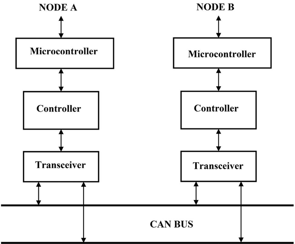
The CAN bus is based on the CSMA/CR (Carrier Sense Multiple Access/Collision Resolution) "mechanism" to prevent frame collisions during transmissions on the bus. Each CAN node monitors the bus and when the node detects that the bus is idle, it may start transmitting data. If other nodes on the bus attempt to send data at the same time, arbitration will take place and the node with the highest priority (i.e., lowest message identifier) will win the arbitration and send its own data. The CAN bus has a simple error detection-and-recovery mechanism. Receiving nodes check the integrity of the messages by looking at the CRC fields. If an error is detected, the other nodes on the bus are informed through error flag messages. Figure 1.3 shows a typical CAN bus implementation with two nodes, A and B. CAN is a Class A/B type network.
Summary of CAN bus features:
• Multi-master bus where each node can be a master
• Multicast reception
• Speeds up to 1 Mbits/s
• Highly dependable
1.2.7 Others
Other automotive bus standards that should be mentioned in this chapter are the SAE J1850 (or simply J1850) which was developed in 1994, and the MI bus (Motorola Interconnect). J1850 was widely used in cars such as GM, Chrysler, and Ford, and this bus is used for diagnostics and data-sharing applications. There are two versions of this standard: PWM (Pulse Width Modulation) with 41.6 Kbps using a two-wire differential physical layer, and VPW (Variable Pulse Width) with 10.4 Kbps using a single-wire physical layer. The two standards are incompatible with each other. The J1850 protocol is frame-based and uses CSMA/ CR arbitration where a frame consists of a Start of Frame, a header byte, data bytes, one byte CRC, and End of Data symbol (a 200-µs Low pulse). Most OBD (On Board Diagnostic) tools support the J1850 protocol for diagnostic purposes. The J1850 standard is old and is being phased out. The J1850 standard is a Class B type network.
The MI bus is a single-wire bus with one master and many slaves. This is a low-cost and low-data rate bus mainly used to drive seats, mirrors, etc. The master is the controller which sends addresses and data to all slaves on the bus. Slaves with matching addresses respond to the request.
1.3 Comparison of automotive bus systems
Currently, one of the most commonly used bus systems is the CAN bus, which can be used at speeds up to 1 Mbps.
Table 1.1 is a summary of commonly used automotive networks (or bus systems), comparing the various systems. For each system, the Class, General information, Bandwidth, and typical Application areas are given.
In general, the LIN bus is used in low-speed automation, such as wiper motor control, rain sensors, etc. CAN is used in engine control, clutch control, and so on. FlexRay is used in very high-performance and safety-critical applications. This is a relatively new bus structure and is hoped to be the automotive standard of the future. MOST is generally used in automotive multimedia, and navigation applications. This bus is optical-based and is tolerant to electrical noise. Byteflight is also a new automotive network system and is well suited to high-demand real-time safety critical applications, such as airbag control. Byteflight is based on fiber optics and as such is much more tolerant to electromagnetic radiation and electrical noise. Intellibus, finally, offers high bandwidth and is mainly used in aerospace applications. It is not as safe and dependable as Byteflight.
Table 1.1: Automotive bus systems
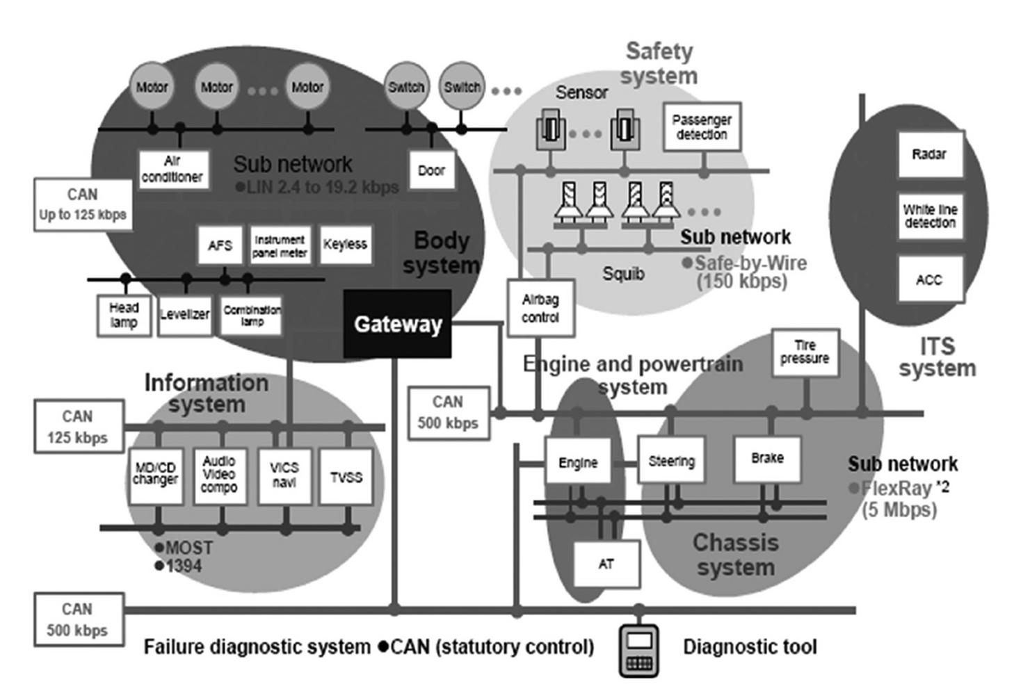
Figure 1.4 and Figure 1.5 show examples of passenger cars where several bus systems are used (source: Introduction to CAN – Application Note REJ05B0804-0100/Rev. 1.00).
In Figure 1.4, the CAN bus can be seen at the left of the figure, connected to the instruments, climate control, lights, steering wheel, power train, and the lock system. The MOST bus can be seen at the lower-left part of the figure, connected to multimedia equipment such as speakers, digital radio, vehicle computer, and navigation equipment. In this particular application, FlexRay can be seen at the lower-right of the figure, connected to the engine, steering system, and brakes. A diagnostic tool, connected to the CAN bus at the bottom-right of the picture, is used to check the state of the vehicle.
In Figure 1.5, headlights, air-conditioning, screen wipers, doors, and windows are controlled by the LIN bus, while FlexRay controls the brakes. Most of the other parts of the car are controlled by the CAN bus.
Today, more than 20 semiconductor manufacturers produce devices with CAN interfaces. Almost all new passenger cars manufactured in Europe and the Far East are equipped with at least one CAN network. CAN is one of the most dominant bus protocols used in passenger cars. Since the year 2000, CAN usage in vehicles has rapidly increased from approximately 120 million CAN devices to around 800 million devices in the year 2007. Currently, this figure is over tens of billions of devices.
CAN and CAN-based higher-level protocols such as CANopen and DeviceNet are becoming more widely accepted by North American manufacturers and it is expected that these protocols will have very high penetrations in most of the industrial and commercial automation markets. In particular, CAN will be used in the following diverse applications within the next five to ten years:
• Passenger cars
• Buses
• Trains
• Maritime electronics
• Aviation electronics
• Factory automation
• Lifts
• Medical equipment
• Programmable machine controllers
• Home entertainment systems
• Domestic appliances
• Military applications
• Space applications
An interesting and important application of the CAN bus will almost certainly be in the medical industry. Medical equipment and devices such as X-ray machines, ultrasound, radiotherapy machines, CAT scanners, MRI machines, and so on could be designed and developed to make use of the CAN bus for their internal communication structures. This approach will simplify the design of machines as well as increase their safety and reliability, also helping to improve ease of maintenance.
1.4 The basic structure of a CAN bus automotive system
It is worthwhile to take a look at the basic structure of a CAN bus-based automotive system before going into the details and theory of the CAN protocol and electronics.
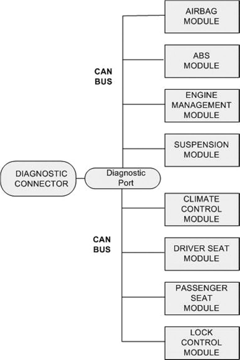
With the development of the CAN bus, there have been major advances in both reliability and safety of automotive electronics. As shown in Figure 1.6, in a CAN bus based automobile, all units are connected to each other over a two-wire bus system. As you will discover in later chapters in more detail, the two wires of the bus are named CAN_LO and CAN_HI. There is full coordination between all the units, and the ECU (Engine Control Unit) is responsible for controlling each unit, making sure that all units operate as expected. In Figure 1.6, the units at the upper part of the figure are time-critical, requiring high priority. Similarly, the units at the lower part of the figure are slow-speed non-critical units requiring lower priorities.
The complete wiring and state of the vehicle can be monitored and interrogated by connecting a diagnostic tool through the diagnostic connector located on the engine. This tool can be a laptop running special software developed by the manufacturer, or a dedicated hand-held diagnostic device can be used to communicate directly with the ECU. Using this tool and with the help of the ECU, it is possible to get information about the state of each unit of the vehicle. For example, we can easily interrogate the Airbag Module and check that it is working properly.
CAN is a two-wire bus system (see Figure 1.7) with resistive connectors at each end of the bus. All the units (or nodes, or CAN-stations) are connected rigidly to the bus using CAN connectors (e.g., T-connectors, End-connectors, and so on).
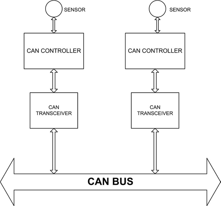
In general, information is received from various sensors (e.g., engine temperature sensor) located in various parts of the vehicle. As shown in Figure 1.8, the sensor information is then passed to a microcontroller, and then to the CAN bus via a CAN controller and transceiver. The function of the CAN transceiver is to make physical connection to the actual CAN bus for communication over the bus. The CAN controller is under the control of the microcontroller and performs the CAN protocol specific functions.
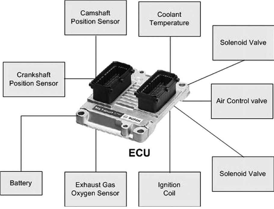
A typical ECU is shown in Figure 1.9. This ECU is suitable for car engines with up to 6 cylinders (ECU model: ECU MS3 Sport, Source: Bosch Motorsport, Equipment For High Performance Vehicles, Edition 2011/11).
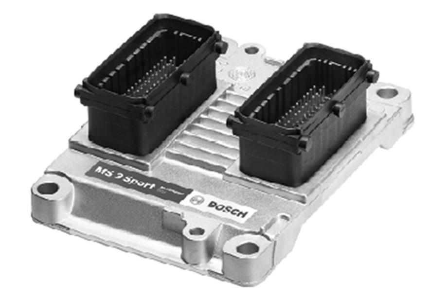
Figure 1.10 shows diagrammatically how the ECU (in the center of the figure) can be connected to other parts of a car. The port labeled "Diagnosis" is used for OBD (On Board Diagnostics) where a hand-held terminal (a scan tool) or a laptop computer can be connected using a special connector and the overall "health" of the vehicle can easily be examined.
1.5 CAN bus advantages
The main benefits of the CAN bus can be summarized as follows:
• Low wiring complexity
• Easy to manage twisted-pair wire bus
• New nodes can be easily added and removed
• Breakdown of a node does not affect the other nodes in the system
• Centralized control
• All devices on the bus can read the same message
• Fail-safe against electromagnetic radiation
• Deals effectively with errors
• Easy diagnostic and maintenance
1.6 CAN bus disadvantages
Some of the disadvantages of the CAN bus include:
• the data rate can be low in some applications (limited to 1 Mbps);
• expensive to implement as special controllers are required;
• complete system shutdown if the main CAN trunk wire is damaged.
1.7 CAN bus main properties
The CAN bus is currently used in many diverse fields, from passenger cars to marine electronics, medical electronics, aviation electronics, and so on. The reason for the wide acceptance of the CAN bus is arguably its high performance, besides reliability, robustness, and safety. The main properties of the CAN bus can be summarized below (the details of these properties will be examined in the next chapters):
• Two-wire twisted-cable bus
• Bus-terminated with resistors at each end
• Up to 1 Mbps speed on the bus (for a 40-m length bus). Higher data rates for shorter bus lengths
• Transfer of up to 8 data bytes at any time
• Messages sent and received as frames under a clearly defined robust protocol
• Multi-master priority-based access to the bus
• Any one node can transmit while other nodes listen
• Bus arbitration if two or more nodes attempt to transmit at the same time
• Broadcast-type message transfer where all nodes can receive the same message
• No node addresses. Nodes accept or reject data on the bus based on message acceptance filtering
• Remote data request where a node can request data from another node
• Error detection and signaling
• Automatic retransmission of messages if failed to transmit (because of the bus arbitration)
• Automatic deactivation of nodes that present consistent errors
1.8 CANopen
CANopen is a high-level communication protocol and specification based on the earlier CAN protocol. CANopen was developed for the vehicle industry in order to simplify and standardize the communication between various devices developed by different manufacturers. Although originally developed for the vehicle industry, it has been used in a wide range of other industries.
Some of the features of CANopen are:
• Up to 128 nodes in the same CAN network
• Multi-master architecture
• Bus length up to 5 km (reduced bit rate at longer lengths)
• Easy high-level access to all devices
• Mixing devices from different manufacturers (manufacturer independence)
• Device synchronization
• High reliability
Although CANopen provides network management and manufacturer independence to a CAN network, it also has the disadvantage that bandwidth is reduced.


