26 minute read
Troubleshooting with Infrared
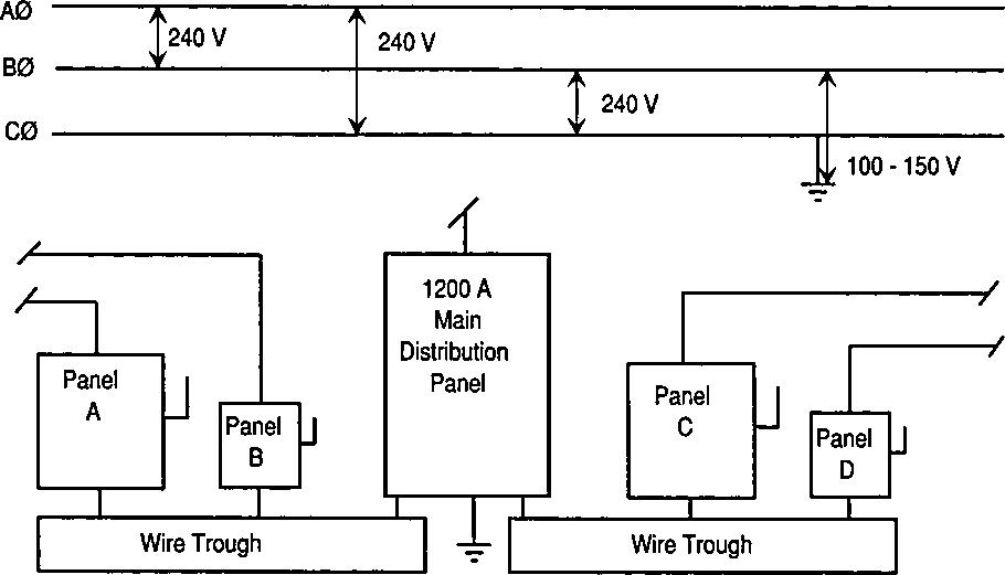
1-6 Diagram of a small industrial electric service.
third phase is only 50 V to ground, then the phase with the lowest reading (50 V) has a partial ground or ground fault. Follow these steps to correct the ground fault:
Advertisement
Step 1. Connect one voltmeter lead to the grounded enclosure of the main distribution panel and the other to the phase terminal that indicated the ground fault. Step 2. Disconnect switch A and check the voltmeter reading. If no change is indicated, disconnect switch B, switch C, and so on, until the voltmeter shows a change (i.e., a reading of approximately 150 V from phase to ground). Step 3. Assuming the voltmeter indicates this reading when switch D is thrown to the
10
OFF position, we then know that the ground fault is located somewhere on this circuit.
Step 4. Switch D disconnects the 400-A circuit feeding eight 15-hp motors and connected as shown in Figure 1-7. One voltmeter lead is connected to the grounded housing of switch D and the other lead to one of the phase terminals. The switch is then turned on. Check each phase terminal until the one with the ground fault is located.
Step 5. Then, one at a time, disconnect the motors from the circuit until the one causing the trouble is found. In other words, when the motor or motor circuit with the ground fault is disconnected, the voltmeter will indicate a normal voltage of approximately 150 V from phase to ground.
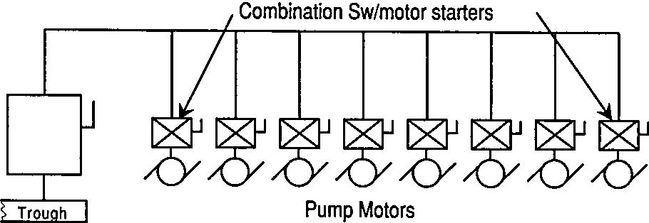
1-7 Wiring diagram for eight 15-hp pump motors fed from a 400-A safety switch. 11
Step 6. Repair the faulty motor or motor circuit according to standard maintenance procedures. When testing electrical circuits with a voltmeter, it is usually best to begin at the main service equipment. First, test the voltage on the line side to see if the incoming service is “hot”; if it is, then test the main fuses or circuit breakers. Check by testing across diagonally from the line to the load side, as shown in Figure 1-8.
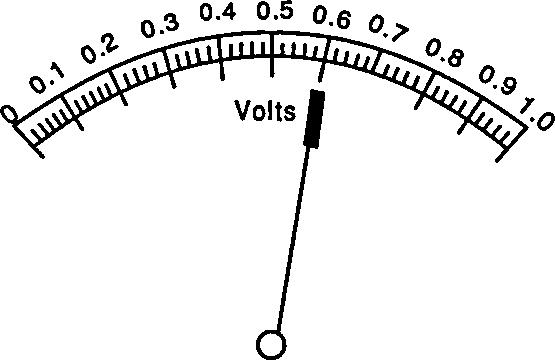
There are various types of analog voltmeters; Figure 1-9 shows two common designs. Meter A is a combination volt-ohm-ammeter with a conventional swinging pointer to indicate the reading; meter B has an audible indicator—similar to the “ting” of an air gauge—and gives only approximate voltage readings.
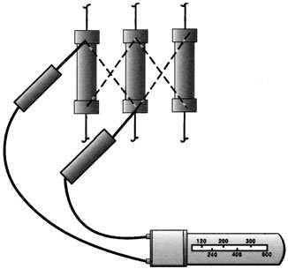
1-8 Testing fuses with a voltmeter. 12

1-9 Common types of voltmeters.
Megohmmeters
The megohmmeter (commonly called a megger in the field) is used to measure the resistance of insulation in megohms (thousands of ohms). Test results indicate the presence of dirt, moisture, and insulation deterioration. Megohmmeter instruction manuals provide detailed information about connecting to and testing various types of equipment. The following sections provide general guidance for common types of troubleshooting tests.
Testing Power Cables
Figure 1-10 shows how to test cable insulation using a megger. After both ends of the cable have been 13
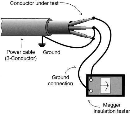
1-10 Testing power cable.
disconnected, test the conductors one at a time, by connecting one of the leads to the conductor under test and connecting the remaining conductors (within the cable) to ground and then to the other (ground) test lead.
Testing DC Motors and Generators
Disconnect a DC motor and a DC generator from its load. Then attach the negative test lead of the megohmmeter to the machine ground and the positive lead to the brush rigging. Measuring the insulation resistance in this manner indicates the overall resistance of all components of the unit.
14
To measure the insulation resistance of the field or armature alone, either remove the brushes or lift them free of the commutator ring and support the brushes using a suitable insulator. Connect one test lead to the frame ground and the other to one of the brushes. Insulation resistance of the field alone will then be indicated, as shown in Figure 1-11. With the brushes still removed from the commutator ring, connect one of the megger test leads to one of the segments of the commutator and the other to the frame ground. The insulating resistance of the armature alone will then be indicated. This test may be repeated for all segments of the commutator.
1-11 Megger connections for testing DC motors and generators. 15
Testing AC Motors
To test an AC motor, first disconnect the motor from its power source, either by using the switch or by disconnecting the wiring at the motor terminals. If the switch is used, remember that the insulation resistances of the connecting wire, switch panel, and contacts will all be measured at the same time. Connect the positive megger lead to one of the motor lines and the negative test lead to the frame of the motor, as shown in Figure 1-12. Compare meter readings to the established insulation resistance minimums.
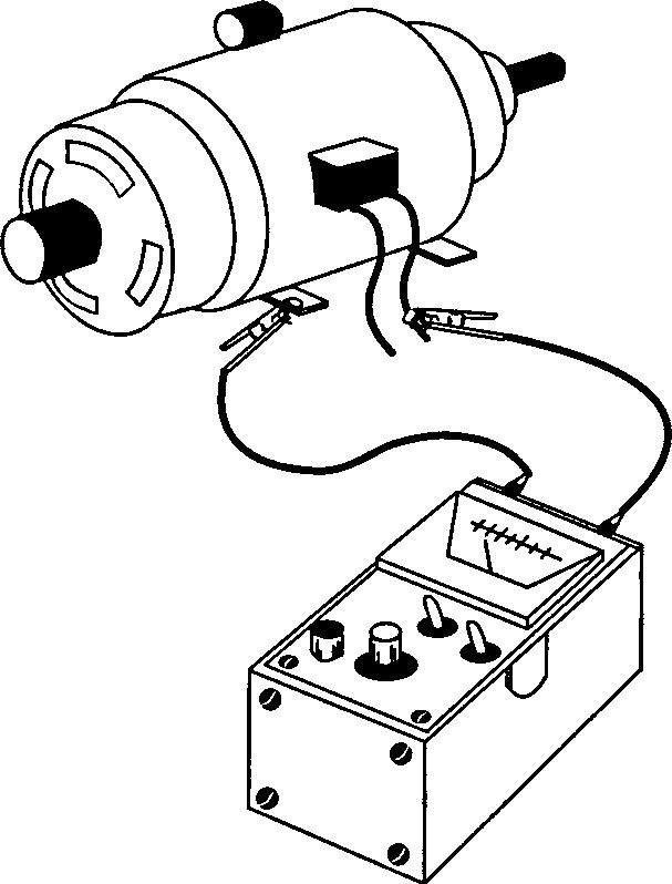
1-12 Method of testing an AC motor. 16
Testing Circuit Breakers
Disconnect the circuit breaker from the line and connect the megger black lead to the frame or ground. Check the insulation resistance of each terminal to ground by connecting the red (positive) lead to each terminal in turn and making the measurements.
Next, open the breaker and measure the insulation resistance between terminals by putting one lead on one terminal and the other on the second for a twoterminal breaker; for a three-pole breaker, check among poles 1-2, 2-3, and 1-3.
Testing Safety Switches and Switchgear
Completely disconnect from line and relay wiring before testing. When testing manually operated switches, measure the insulation resistance from ground to terminals and between terminals. When testing electrically operated switches check the insulation resistance of the coil or coils and contacts. For coils, connect one megger lead to one of the coil leads and the other to ground. Next, test between the coil lead and core iron or solenoid element.
Testing Ground Resistance
Figure 1-13 shows the simplest method for testing the resistance of earth. The direct or two-terminal test consists of connecting terminals P1 and C1 of the megohmmeter to the ground under test, and terminals P2 and C2 to an all-metal underground water-piping system. If the water piping covers a large area, its resistance should be very low (only be
17
18
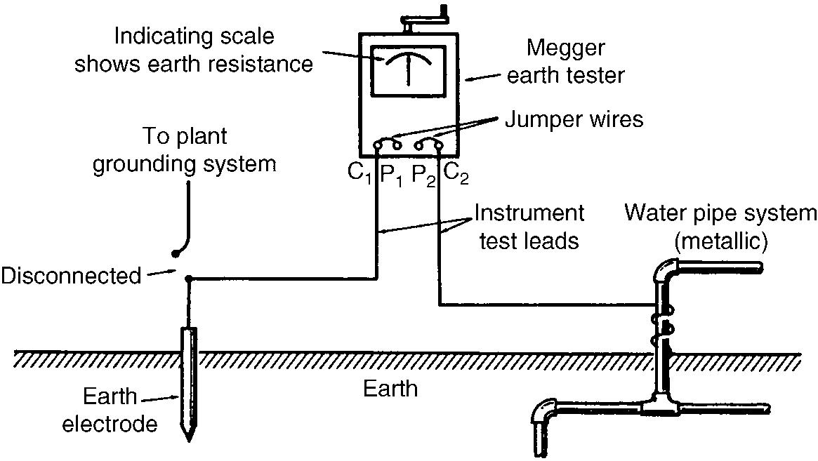
1-13 Direct method of earth-resistance testing.
a fraction of an ohm). Thus, the megohmmeter reading will be that of the earth or grounding electrode being tested.
Miscellaneous Testing Instruments
Ammeters, voltmeters, and megohmmeters are the most common analog devices used for field testing and troubleshooting applications. However, several other specialized types of test instruments should be mentioned briefly.
Frequency Meter
Frequency is the number of cycles completed each second by a given AC voltage, usually expressed in hertz (Hz); 1 Hz = 1 cycle per second.
The frequency meter is used with AC powerproducing devices like generators to ensure that the correct frequency is being produced. Failure to produce the correct frequency can result in overheating and component damage.
Power Factor Meter
Power factor is the ratio of the true power (voltamperes) to apparent power (watts), and it depends on the phase difference between current and voltage.
Three-phase power factor meters are installed in switchboards. Many utilities charge large commercial and industrial users a penalty if power factor falls below 90 percent; so these users try to maintain high power factor at all times. A high power factor provides better voltage regulation and stability.
19
Tachometers
A tachometer is a device that indicates or records the speed of rotating equipment (motors and generators) in revolutions per minute (rpm). There are several different types:
Vibrating-reed Tachometer This instrument is simply held against the motor, turbine, pump, compressor, or other rotating equipment, and the speed is shown by the vibration of a steel reed, which is tuned to a certain standard speed.
Photo Tachometer This instrument aims a light at the rotating shaft on which there is a contrasting color such as a mark, a chalk line, or a light-reflective strip or tape. The rotational speed in rpm is read from an indicating scale. Photo tachometers are especially useful on relatively inaccessible rotational equipment such as motors, fans, grinding wheels, and other similar machines where it is difficult, if not impossible, to make contact with the rotational unit.
Electric Tachometer This consists of a small generator that is belted or geared to the equipment whose speed is to be measured. The voltage produced in the generator varies directly with the rotational speed of the generator. Since this speed is directly proportional to the speed of the machine under test, the amount of the generated voltage is a measure of the speed. 20
Footcandle Meter
A footcandle meter consists of a photosensitive element and a meter that indicates the average illumination of a room or other space in footcandles. Typical footcandle meters can read light intensity from 1 to 500 footcandles or more.
To use the footcandle meter, first remove the cover. Hold the meter in a position so the cell is facing toward the light source and at the level of the work plane where the illumination is required. The shadow of your body should not be allowed to fall on the cell during tests. A number of such tests at various points in a room or area will give the average illumination level in footcandles. Readings are taken directly from the meter scale. Electrical Thermometers For the measurement of temperatures, there are three basic types of electrical thermometers. 1. Resistance thermometers operate on the principle that the resistance of a metal varies in direct proportion to its temperature. They are normally used for temperatures up to approximately 1500°F. 2. Thermocouples operate on the principle that a difference in temperature in different metals generates a voltage, and are used for measuring temperatures up to about 3000°F. 3. Radiation pyrometers and optical pyrometers are generally used for temperatures above 3000°F. They combine the principle of the
21
thermocouple with the effect of radiation of heat and light.
Phase-Sequence Indicator
A common phase-sequence indicator is designed for use in conjunction with any multimeter that can measure AC voltage. Most can be used on circuits with line voltages up to 550 VAC, provided the instrument used with the indicator has a rating this high.
To use the phase-sequence indicator, set the multimeter to the proper voltage range. This can be determined (if it is not known) by measuring the line voltage before connecting the phase-sequence indicator. Next, connect the two black leads of the indicator to the voltage test leads of the meter. Connect the red, yellow, and black adapter leads to the circuit in any order and check the meter for a voltage reading.
If the meter reading is higher than the original circuit voltage measured, then the phase sequence is black-yellow-red. If the meter reading is lower than the original circuit voltage measured, then the phase sequence is red-yellow-black. If the reading is the same as the first reading, then one phase is open.
Cable-Length Meters
Cable-length meters measure the length and condition of a cable by sending a signal down the cable and then reading the signal that is reflected back. These instruments are also called time-domain reflectometers (TDRs). A similar instrument used to measure the length of fiber optic cables is called an optical timedomain reflectometer (ODTR). 22
Power Quality Analyzers
Power quality analyzers are portable test instruments similar in construction to the digital multimeters described in greater detail in Chapter 2. However, unlike DMMs, which typically measure only one property of electrical circuits at a time, power quality analyzers have dual probes that allow both voltage and current to be measured simultaneously. Power quality analyzers can also measure frequency and harmonics.
The results of these readings are displayed graphically, as shown in Figure 1-14. The ability to measure

1-14 Power quality analyzer display showing voltage on top, current on bottom, and time stamp at upper right. 23
and display multiple circuit characteristics at the same time is useful in troubleshooting power quality problems in power distribution systems. This subject is covered more fully in Chapter 9.
24
CHAPTER 2 Digital Multimeters
The five core functions of handheld meters are measuring AC and DC voltage, AC and DC current, and resistance. Digital multimeters (DMMs) containing microprocessors perform these functions, but their built-in computing power allows them to offer other capabilities as well: ● Greater accuracy ● Better displays ● Accessory adapters for taking additional types of measurements ● Data-handling capabilities
Figure 2-1 shows a typical DMM. The range of features, options, and accessories offered on DMMs varies widely from one brand and model to the next. The most important are summarized in the next sections.
Greater Accuracy
The accuracy of DMM readings is typically from 0.5 to 0.1 percent, and results can be displayed to two or three decimal places. While this level of accuracy is not always needed for field troubleshooting of electromechanical
25
1
2
4
Hz
V RANGE
OFF A
HOLD
A COM V 3
5
6
1 LCD display with numerical readout. 2 Measurement function knob. 3 Soft-keys—Use with measurement function knob to select measurements. 4 Range button—Use to set measurement range. 5 Hold button—Use to freeze display. 6 Input connectors. Note: Some DMMs have a separate function knob setting and/or input connector for A/mA.. 2-1 Digital multimeter (DMM).
equipment, it can be useful in applications involving electronic circuits.
Better Displays
Digital multimeter displays show numerals and graphical patterns (such as waveforms) rather than
26
swinging needles. Displays are large enough to read from a distance, and some can display two or more items simultaneously, such as voltage and frequency. Most DMMs have a liquid-crystal diode display that expresses readings in contrasting shades of gray. Many models also have a backlighting switch for taking readings under poorly lighted areas. Maximum display readouts are always one digit less than the marked range. For example, the 200-Ω resistance range reads between 0.0 and 199.9 Ω (Figure 2-3). If higher resistance is present, “OL” or “1” (overlimit or out-of-range indication) shows in the display. When this happens, the rotary switch should be rotated to a higher range.
Hold, Freeze, or Capture Mode
On many DMMs, pressing a “hold” button freezes a reading on the display screen so that the meter can be taken to a more convenient area for viewing. This feature is particularly useful in tight spaces with poor visibility, or when it isn’t convenient to read the display at the same time you’re taking a measurement on a circuit or piece of electrical equipment.
Construction and Convenience Features
Most DMMs have a shock-resistant heavy-duty case with a belt holster, and a tilt stand for placing on flat surfaces such as a table. Many also have handles that allow them to be hung at eye level, an advantage in many troubleshooting applications where space is tight. DMMs are very rugged and can last for years of trouble-free operation under heavy-duty use.
27
Many units can operate with the same 9 V battery for 2000 to 3000 hours because the solid-state circuits and LCD display have a very low current drain. Some models constantly display a battery status icon on the screen. In other models, a “Lo Bat” warning appears or the decimal point in the digital display blinks when the battery is nearing its end of life.
Function Selection
DMMs have a dial or rotary switch that lets you select basic measurement functions (such as voltage, current, resistance, frequency, and temperature). Higher-priced DMMs also have either four or eight “soft keys.” These are push buttons whose function depends upon the type of measurement selected.
When the dial is rotated to select a basic measurement function, such as current, some or all of these soft keys may become active. When this happens, the purpose of that key is displayed at the bottom of the LCD display (i.e., just above the soft keys). For some measurement functions, not all soft keys will be active.
Inputs and Test Leads
Most DMMs have three test jacks or inputs: voltage (V), current (A), and common or return (COM). The inputs marked V and A are normally colored red, as are the various test leads that plug into them. The common input, which is used for all measurement functions, is normally colored black, as is the common test lead that plugs into it.
28
NOTE: Some units also have a fourth separate input for current measurements in the milliampere (mA) or microampere (µA) range.
Accessories
DMM manufacturers offer a wide array of accessories that both extend measurement ranges and allow the instrument to be used for additional types of measurements, including: ● Power ● Power factor ● Energy (kWh) ● Harmonics ● Temperature (single probe, and dual probe for differential) ● Light intensity ● Relative humidity ● Carbon monoxide (CO) ● Airflow
General Instructions for Using Digital Multimeters
Because exact capabilities and features of different DMMs vary, it is important to read the manufacturer’s manual supplied with the unit. The following procedures apply to DMMs generally.
Measuring Voltage
Select a voltage measurement range. Connect test leads to the V and COM inputs. Place the DMM in
29
parallel with the voltage source and load to measure voltage (Figure 2-2). Never place the meter in series with the circuit when measuring voltage.
Measuring Current
Select a current measurement range. Connect test leads to the A and COM inputs. Place the DMM in series with the voltage source and load to measure current. Never place the meter across (in parallel with) the circuit when measuring amperes. The current in solid-state circuits such as printed circuit boards is measured in milliamperes (mA) or microamperes (µA) (Figure 2-3).
Measuring Resistance
Select resistance test (Ω). Plug the red test lead into the voltage (V) input and the black lead into the common (COM) input. Place the probe tips across the suspected resistor or leaky component. A good resistor should read within plus or minus 10 percent of its rating.
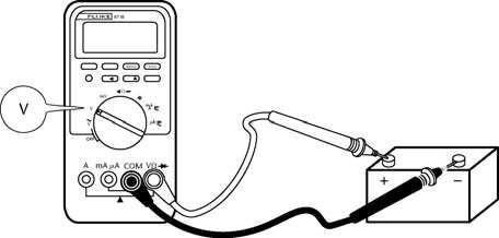
2-2 Measuring voltage. 30
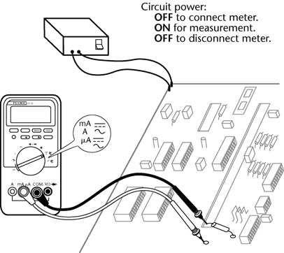
2-3 Measuring current.
Thus, a sound 330-Ω resistor would register between 300 and 360 Ω (suspect a burned resistor if the reading is less than 300 Ω). It may be necessary to isolate the resistor or other component from the circuit to get an accurate reading (Figure 2-4).
Testing Continuity
Select resistance test (Ω). Connect test leads to the V and COM inputs. Some DMMs sound a constant tone or noise when making continuity and diode tests. A constant tone indicates proper continuity. No tone (or a broken, stop-start sound) indicates an open circuit, intermittent faults, or loose connections (Figure 2-5). 31
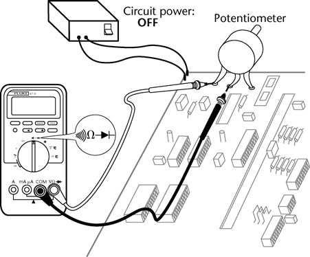
2-4 Measuring resistance.
Measuring Capacitance
Select capacitance measurement ( ). Connect test leads to the V and COM inputs. Capacitors should be isolated from the circuit to provide accurate DMM measurements (Figure 2-6). Discharge large filter capacitors before attempting to measure them.
Measuring Frequency
Select frequency measurement (Hz). Connect test leads to the V and COM inputs. As with other DMM measurements, start at the highest band and switch down to the correct frequency range.
32
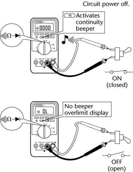
2-5 Testing for continuity.
Testing Diodes
Select diode test ( ). Connect test leads to the V and COM inputs. Some DMMs have an audible tone for the
33
2-6 Measuring capacitance.
34
diode test. Touch the red probe to the anode and the black test probe to the cathode terminal of the diode. The cathode may be marked with a black or white line at one end of the diode (Figure 2-7). A normal silicon diode reading will indicate only an overlimit measurement (OL or 1) if the test leads are reversed.
Typical reading Test leads OK
Leads reversed
2-7 Testing diodes. 35
Digital Multimeter Safety Features
Hand-held test meters should never be connected to any electrical equipment or system operating at a voltage that exceeds the meter’s rating. While this is an important safety precaution when using any meter, it is even more important with DMMs.
Digital meters are more sensitive than older analog models to transient overvoltages caused by nearby lightning strikes, utility switching, motor starting, and capacitor switching. High-voltage transients can damage the electronic circuitry inside DMMs, and in severe cases cause meters to explode.
DMMs have internal fuses that function to protect the test instrument (and the person using it) from harm when taking readings on systems of higher voltage or current rating than the DMM.
However, it is still extremely important never to try to take a reading on a system whose voltage or current is higher than the rating of the DMM itself.
Underwriters Laboratories Inc. has established safety ratings for DMMs. UL standard 3111-1 defines four energy-rating categories for test and measurement equipment, with CAT IV offering the highest level of protection.
CAT IV covers utility connections and all outdoor conductors (because of lightning hazards). Examples include service entrance equipment, watt-hour meters, and switchboards/switchgears.
CAT III covers power distribution equipment within buildings and similar structures. This includes panelboards, feeders, busways, motors, and lighting.
36
CAT II covers single-phase, receptacle-connected loads located more than 10 m from a CAT III power source or more than 20 m from a CAT IV source.
CAT I covers electronic and low-energy equipment.
DMMs are certified to these four categories by UL and other independent testing laboratories. The certification level is marked directly on the DMMs, and often included in advertising for them. Higher-rated meters can safely be used for lower-level measurement functions.
IMPORTANT
The category number of a DMM is more important than its voltage rating when determining the degree of protection that it provides. In other words, a CAT III, 600 V meter offers better protection against high-energy transients than a CAT II, 1000 V meter.
General Safety Precautions for Using Digital Multimeters
● When schematic drawings, building plans, or other documentation is available, check for expected ranges of voltage, current, resistance, and other properties before taking measurements with the DMM.
Rotate the function switch to the appropriate range. ● If the appropriate range for a given mea-
37
surement is not known, start at the highest scale for voltage, current, and so on. Select progressively lower ranges until the measurement falls within the correct range. ● If the overlimit display (OL or 1) comes on, turn to a higher measurement scale. ● Remove test leads from the circuit or device being tested when changing the measurement range. ● Resistance and diode measurements should only be taken in de-energized circuits. ● Discharge all capacitors before taking capacitance readings with a DMM.
38
CHAPTER 3 Troubleshooting Basics
Much of the work performed by electricians and technicians involves the repair and maintenance of electrical equipment and systems. To maintain such systems at peak performance, workers must have a good knowledge of what is commonly referred to as troubleshooting—the ability to determine the cause of a malfunction and then correct it.
Troubleshooting covers a wide range of problems, from small jobs such as finding a short circuit or ground fault in a home appliance to tracing out defects in a complex industrial installation. The basic principles used are the same in either case. Troubleshooting requires a thorough knowledge of electrical theory and testing equipment, combined with a systematic and methodical approach to finding and diagnosing problems.
The following general tips and principles are intended to help define the troubleshooting process. Specific types of electrical equipment and systems are described in later chapters of this book.
39
Think Before Acting
Study the problem thoroughly, and ask yourself these questions: ● What were the warning signs preceding the trouble? ● What previous repair and maintenance work has been done? ● Has similar trouble occurred before? ● If the circuit, component, or piece of equipment still operates, is it safe to continue operation before further testing?
The answers to these questions can usually be obtained by: ● Questioning the owner or operator of the equipment. ● Taking time to think the problem through. ● Looking for additional symptoms. ● Consulting troubleshooting charts. ● Checking the simplest things first. ● Referring to repair and maintenance records. ● Checking with calibrated instruments. ● Double-checking all conclusions before beginning any repair on the equipment or circuit components.
The source of many problems is not one part alone, but the relationship of one part to another. For instance, a tripped circuit breaker may be reset to restart a piece of equipment, but what caused the breaker to trip in the 40
first place? It could have been caused by a vibrating “hot” conductor momentarily coming into contact with a ground, or a loose connection could eventually cause overheating, or any number of other causes.
Too often, electrically operated equipment is completely disassembled in search of the cause of a certain complaint, and all evidence is destroyed during disassembly operations. Check again to be certain an easy solution to the problem has not been overlooked.
Find and Correct the Cause of Trouble
After an electrical failure has been corrected in any type of electrical circuit or piece of equipment, be sure to locate and correct the cause so the same failure will not be repeated. Further investigation may reveal other faulty components. Also be aware that although troubleshooting charts and procedures greatly help in diagnosing malfunctions, they can never be complete; there are too many variations and solutions for a given problem.
Note:
Always check the easiest and obvious things first; following this simple rule will save time and trouble.
To solve electrical problems consistently, you must first understand the basic parts of electrical circuits, how they function, and for what purpose. If you know that a particular part is not performing its job,
41
then the cause of the malfunction must be within this part or series of parts.
Intermittent Faults
Finding and diagnosing intermittent faults, where a short, open, or other problem occurs only temporarily, or only under certain conditions, is always a difficult troubleshooting problem. Two features found on most DMMs can help with identifying intermittent faults. Continuity capture mode This feature is useful for finding intermittent connections with small gauge wires and wiring bundles, and even intermittent relay contact. To check for intermittent opens, place the leads across the normally closed or shorted connection and select Continuity Capture mode on the DMM. Wiggle the wire(s) and heat the connection with a heat gun, or cool it with circuit cooler to make the intermittent open appear. When the open is captured (as short as 250 µs), the display shows a transition from open to a short.
Intermittent shorts can be found the same way, by connecting to a normally open circuit and using the wiggling and heating/cooling techniques to capture the short. The only difference is that the transition lines will go from the bottom of the display to the top. Recording mode Sometimes intermittent faults cannot be successfully induced while observing the DMM display. Some higher-end units have a recording mode with a date and time stamp. This type of DMM can be left
42
connected to a circuit or piece of electrical equipment for an extended period of time to record the occurrence of an intermittent fault. The date and time of occurrence may provide clues that allow the electrician or technician to trace the cause of the fault (Figure 3-1).
Working Safely Is Critical
Electrical troubleshooting is inherently hazardous. The hazards of working with electricity include shock and electrocution, fire, and arc-blast injuries.
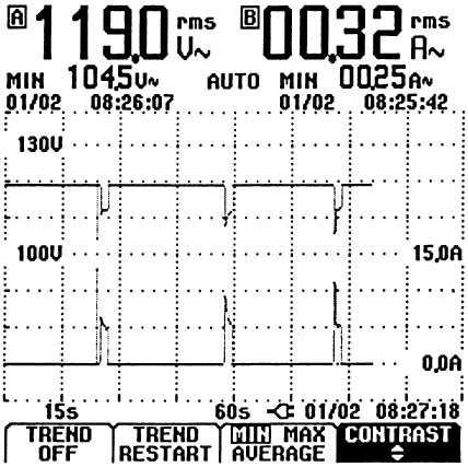
3-1 Recording DMM display.
43
Arc-blast is a high energy “explosion” that can occur when something happens such as accidentally shorting across transformer terminals or the bus bars in a panelboard—for example, by dropping a metal screwdriver.
NFPA 70E-2004, Standard for Electrical Safety in the Workplace, is the governing standard for protection against electrical hazards in the workplace. Troubleshooting is particularly hazardous, because electricians and technicians are often working on energized (“live”) equipment and systems.
In addition to electrical hazards, testing and maintenance work also involves other dangers such as falling from roofs and ladders, and accidents with power tools. Entire books have been written about electrical safety. This section summarizes essential safety precautions when performing troubleshooting on electrical equipment and systems. It is based on the safety rules of NFPA 70E.
Qualified persons Article 100 of the National Electrical Code defines a qualified person as “One who has skills and knowledge related to the construction and operation of the electrical equipment and installations and has received safety training on the hazards involved.” NFPA 70E uses the same definition.
To help prevent accidents and injuries, only qualified persons meeting this definition should perform electrical troubleshooting work. Untrained, unqualified, persons should never be allowed to do electrical testing and maintenance.
44
Personal protective equipment Troubleshooting often involves testing of energized circuits and equipment. Because of the dangers, NFPA 70E defines electrical testing as a hazardous task that should only be performed wearing appropriate personal protective equipment (PPE). The minimum PPE for electrical troubleshooting work is as follows:
● Long-sleeved shirt and pants of natural fibers, such as cotton or wool. Don’t wear synthetic fabrics such as polyester or nylon, which can melt and catch fire in case of an electrical arc-blast. ● Steel-toed boots. ● Only plastic hard hats should be worn for electrical work. ● Safety goggles or glasses. ● Work gloves.
In addition, don’t wear metal jewelry such as rings, wristwatches, chains, and earrings when working around electrical circuits and equipment. Gold and silver are excellent conductors of electricity.
Working on energized equipment such as panelboards and motor control centers with the covers off is particularly hazardous. A short-circuit or faulty circuit breaker in an energized panelboard could result in an arc-blast, causing severe burns and other injuries to the workers involved. NFPA 70E requires the following additional PPE when performing “switching operations” on live electrical equipment: 45
● Fire-rated (FR) clothing. ● FR flash jackets or suits with hoods over the FR clothing. ● Arc-rated face shields. ● Hearing protection. ● Voltage-rated gloves. ● Voltage-rated tools.
PPE is a complex subject. The correct PPE needed depends upon the type of work being done, the operating voltage, and the available fault current. For complete information about this subject, see NFPA 70E-2004, Standard for Electrical Safety in the Workplace. Avoid working “live” Electrical testing must often be performed on energized circuits and equipment. But the safest technique for doing tasks such as repairing and replacing faulty components is to turn the power off. PPE isn’t needed when there are no electrical hazards to protect against. So, the simplest safety rule for electrical maintenance work is—Don’t work live!
Lockout/tagout When electrical systems are de-energized to perform maintenance work safely, precautions must be taken to insure that circuits are not accidentally turned back on while the work is going on.
Lockout/tagout is the preferred method of controlling energy sources to minimize hazards to personnel. The details are complex, and beyond the scope of this book. But every company should have an official lockout/tagout procedure, which should always be 46
followed when electrical circuits are de-energized during construction or maintenance work. For more information, refer to NFPA 70E, Annex G “Sample Lockout/Tagout Procedure.”
47


