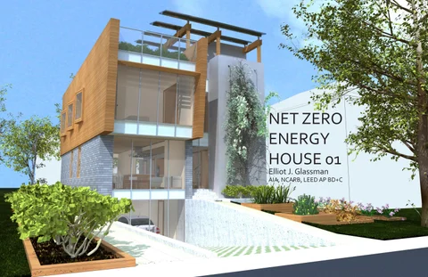
NET ZERO ENERGY HOUSE 01
 Elliot J. Glassman AIA, NCARB, LEED AP BD+C
Introduction Defining Net Zero Renewable Energy Exterior Renderings Interior Renderings Site Planning Floor Area Organizing Principles Floor Plans Services Construction Energy and Water
Introduction Defining Net Zero Renewable Energy
The typology of the stand-alone single family house is an interesting contradiction in terms of environmental sustainability.
On the one hand, it is one of the least sustainable model for development that there is. The single family home has a large ratio of exterior envelope compared to the amount of floor area it encloses. This means more thermal energy is lost through the envelope per square foot than attached or multistory structures, leading to larger heating and cooling usage and costs.
Additionally, the single family home is found in suburban environments that contain substantially less people per acre than the urban environment. The lack of density prevents walkability, hinders public transportation networks, and necessitates the use of the car to provide for even the most basic daily needs. It also requires more infrastructure be provided per residence in terms of road access and utility distribution. This consumes a lot of resources.
The single family home represents an inversion of the urban experience, one in which amenities and entertainment are found inside the home instead of in the public realm. Accommodating these extra uses is in part responsible for the growth in the size of the average single family home, requiring more energy to operate them.
Yet, the single family home it is the easiest common building typology to design as a net zero energy structure. With a lower energy use intensity (EUI) compared to commercial buildings and a greater proportion of roof space to enclosed floor area than multi-family residential buildings, it is possible to use solar power to generate as much energy as the building uses on an annual basis. Residential zoning requirements such as height restrictions and yard setbacks increase the chances of unrestricted solar access to maximize energy production.
Though development trends are beginning to favor walkable, transit oriented neighborhoods, the stand-
alone single family house still represents a significant percentage of American housing stock and therefore a more ecologically minded response must be considered.
One emergent counteraction to the McMansioning of the American suburb is the Tiny House movement.
A Tiny House is an house that is only 100-400 square feet in area. This is the opposite extreme which may not be right for everyone, particularly those needing the space to raise a family.
Therefore, the project seeks to provide a design for a compact yet livable net zero energy house, meant to advance typical notions of what a house could be without any radical departure from the typology. The goals of the project are to:
• Provide an efficient, flexible, and open interior, resulting in a compact dwelling that still offers all the amenities of a larger home. This will reduce the construction costs of the house and the energy used to operate it.
• Use efficient mechanical systems that reduce annual energy consumption while providing superior thermal comfort. The floor plan should also allow efficient distribution to reduce the spatial allocation and first costs for piping and duct runs.
• Use a construction system that will minimize complexity, enable a quick and cost effective assembly, and provide a tight, energy efficient envelope.
There are many different possible designs that could satisfy these three criteria. The proposed design presented here is just one option of any number of creative, well designed solutions that are possible. Other designs could be generated exist based on varying owner requirements, site conditions, and climatic responses.
A Net Zero Energy Building (NZEB) is one which produces as much energy as it uses on an annual basis.
Most Net Zero Energy Buildings are still connected to the electric grid, allowing for the grid electricity to be used when renewable energy generation cannot meet the building’s energy load.
When the on-site energy generation exceeds the building energy requirements, the surplus energy is exported back to the utility grid. The excess energy production offsets later periods of excess demand, resulting in a net energy consumption of zero.
On-site energy generation using renewable sources is better for the environment than using electricity for the grid since so much of the energy produced for a typical grid is lost in the transmission over long distances. Renewable energy generation does not pollute the air or water like conventional electricity generation does.
On-site energy generation for residential buildings is typically provided by photovoltaic (PV) panels, most commonly referred to as solar panels. The efficiency at which the PV panels convert solar radiation to usable electricity is constantly increasing with new technological breakthroughs. Simultaneously, the costs of the equipment and installation is decreasing as this form of renewable energy becomes more commonplace.
Combined with tax incentives and increasing energy costs, solar power is becoming a very affordable investment. Right now, the cost of solar produced energy is comparable or a little less per kWh than energy produced from the grid.
The more the energy usage of a house is reduced, the fewer panels are needed to provide for the energy demand, reducing costs for the PV array.


Interior Renderings


Lot Constraints
The site is based on a small suburban lot of 50’ by 100’. The site restrictions include a 25’ front and rear yard setbacks and 10’ side yard setbacks as per typical suburban zoning requirements.


Site Ecology and Water Management
If all the residential lawns in the US were added together, it would create an area roughly equal to the size of Virginia. These lawns are thirsty, accounting for 30% of a typical household’s annual water use.


A typical suburban grass lawn is a monoculture, while nature thrives on biodiversity. A comprehensive ecology will be created on the site that provides a diverse landscape of various plants and trees. Native and adapted plants will be used to minimize irrigation requirements. Vegetation with complex branch structures are better at improving air quality and preventing rainwater runoff than grass lawns. Therefore, the vegetation will become part of the water management system while helping to reduce particulate matter in the air.
Garden areas will be reserved to provide fruits and vegetables for food. The garden will be irrigated using a drip system which uses less water than conventional spray watering.


The roof of the house is a vegetated roof while the walls incorporate vertical plantings. Roof drains will be used to collect rainwater for irrigation and for use in the house.


Typical asphalt is impervious to water, preventing rain from infiltrating the ground and causing flooding issues. The driveway will be made of pervious pavement that provides a driveable surface but one that allows water to percolate through to the ground.

A. Roof garden
B. Patio (below)
C. 13 kW PV Array
D. Driveway made of pervious pavement to allow water infiltration into the ground
E. Garden using drip irritation
F. Main entry
G. Stairs down to apartment
H. Horizontal loops for ground heat exchange in side yard (buried). This means that the project needs no exterior mechanical equipment that takes up space and creates noise


Organization Diagram Structural Walls
Organizing Principles
The core organizing principle is based on Louis I. Kahn’s formal separation between ‘served’ and ‘servant’ spaces. ‘Servant’ spaces are stairwells, corridors, restrooms, or any other back-of-house function such as storage space or mechanical rooms that ‘serve’ other spaces.
A solid core to the east contains all the ‘servant’ spaces so that the rest of the space to the west can remain open. This also allows the utilities such as plumbing and air ducts to be concentrated in one area, limiting branching.
The served and servant spaces are linked by a central circulation zone. These different zones are all composed as adjacent narrow bands running north to south. The long east and west exposures are conceived as mostly solid walls with a few punched openings. This is to provide structural bearing walls, protect from low angle sun on the east and west, and provide a well-insulated envelope. The north and south walls are more transparent.
The ground floor is for common space, while the upper floor is for private spaces. The basement has mechanical areas and an apartment to let.
Built-in
are used throughout the project to provide
and give a uniform look to the spaces, keeping the floor area open and clear.

Basement
The basement contains the garage, mechanical rooms, and a one bedroom apartment that can be rented out.
Basement Plan Scale: 3/16” = 1’-0”
Bedroom 27 Corridor 28
Living/Dining Room 26
Kitchen 32
Corridor 24 Garage 25
W.I.C. 29 Bathroom 30 Ground Source Heat Pump Room 31
A. Lightwell B. Entry patio C. Door to apartment for flexibility. If the apartment is rented out, the door can be locked from the house. If owner has family living in apartment or wants to add apartment to living space, direct access to the house is possible
Storage/Meter Room 33
A. Built-in storage cabinets
B. Movable partition that closes off the den for use as a guest suite. Folds into cabinet when not in use to provide an open and visually connected space

C. Movable partition that closes off corridor for guest suite. In deployed position, creates opening to den so that the guest has access to bathroom and close
Ground Floor
The ground floor is designed as a long continuous space. It is subdivided by furniture which can be rearranged as needed, giving flexibility in use to the space.
The den and corridor features movable partitions that can closed off when need to convert the space temporarily into a guest suite.
Second Floor
The upper floor contains the bedrooms including the master suite. All bedrooms have built-in cabinets.
The laundry machines are located on this floor to provide close proximity to the bedrooms. Waste heat from the dryer is captured and used to preheat domestic hot water.

Floor
Roof
Unlike most single family homes, the proposed design has a flat roof. This allows the space to be utilized by the occupants as an activity space. There is a patio area and a gas hookup for a barbecue grill.

The PV panels are incorporated into a trellis that provides shade for the patio and seating area.
Part of the roof is vegetated, creating an additional amenity for the residents but also providing numerous environmental benefits. The vegetated roof offers additional roof insulation, helps mitigate heat island effect and storm water runoff, and contributes to biodiversity.
The glass doors out to the roof allow natural light to filter down the stairwell. When open, the glass doors can act an exhaust from the stairwell, helping to aid in natural ventilation of the spaces down below through the stack effect.
Services
Heating and Cooling
The mechanical conditioning is handled by a hydronic radiant based system rather than a forced air system. Radiant systems are more energy efficient, provide superior thermal comfort, and greatly reduce duct sizes since air is only needed only for ventilation and not for space conditioning.
Radiant floors provide uniform, low temperature heating while hydronic units in the ceiling provide cooling. Water is a more efficient medium for transferring heat than air, and temperature of the water can be more moderate to provide the same amount of cooling or heating, saving on energy costs. The systems use radiation and convection to transfer or remove heat, saving on fan energy from moving air.
The central plant is a ground source heat pump (GSHP), which produces hot and cold water for the hydronic systems and can preheat the domestic hot water. The GSHP takes advantage of the stable ground temperatures to generate heating and cooling in an a more energy efficient manner than rejecting it to the outdoors where temperature varies.
A small dedicated outdoor air system takes ventilation air in from the roof and distributes it to the spaces from vertical registers on the soffit of the hallway. A heat recovery unit on the roof preconditions the incoming air using heat recovered from the mechanical exhaust from the bathrooms, kitchen, and laundry.
Natural Ventilation
The windows of the house will be operable to take advantage of natural ventilation when outdoor conditions permit. The stairwell can help promote ventilation across the floor plate by providing a high level exhaust, creating a stack effect.
A. Dedicated outdoor air unit for ventilation. Heat recovery takes heat from exhaust air to preheat incoming air
B. Reduced duct sizes. Since the air is for ventilation only and not for heating, the volume of air to be circulated is 1/4 of a typical central air system
C. Ducts run through central wall. Air is distributed through short duct runs over the circulation zone
D. Radiant floor uses hot water from the ground source heat pump to provide radiant heat

E. Horizontal heat exchange loops for ground source heat pump
A. Dedicated outdoor air unit for ventilation. Heat recovery rejects heat from incoming air to exhaust air
B. Reduced duct sizes. Since the air is for ventilation only and not for cooling, the volume of air to be circulated is 1/4 of a typical central air system
C. Ducts run through central wall. Air is distributed through short duct runs over the circulation zone
D. Hydronic unit uses chilled water from the ground source heat pump to provide cooling. Convection currents help circulate air without fans
E. Horizontal heat exchange loops for ground source heat pump
Heating Mode
Cooling Mode
Services
A. Operable windows
B. Open stairs facilitate air movement
C. High outlet creates pressure differentials that help exhaust air
A. Roof drains collect rainwater
B. Water collects in storage tank along with recycled sink and shower water
C. Greywater is reused for irrigation and toilet flushing
D. Solar Panels
Plumbing
All the vertical ducts for the ventilation system are located in a dedicated mechanical wall along with the electrical and plumbing risers. The bathrooms, kitchen, and laundry are located along this wall to concentrate the services in one location and minimize horizontal piping and ducting runs.
Garden Level 20' 0"
Garden Level 20' - 0"
Level 2 10' 0"
Level 2 10' - 0"
Level 1 0' - 0"
Roof 28' 0" Basement -9' - 0"
Level 1 0' - 0"
Grade -4' - 6"
Grade -4' - 6"
Roof 28' - 0" Basement -9' - 0"
Natural Ventilation Mode Water Collection And Recycling
Garden Level 20' - 0"
Garden Level 20' - 0"
Toilet flushing and landscape irrigation are water uses in the house that do not require potable (drinkable) water. Greywater from sinks and drains can also be recycled for these uses together with rainwater that is collected from roof drains. The water is collected and stored in a cistern below the basement floor slab.
Renewable energy
Level 2 10' - 0"
Level 2 10' - 0"
The top of the roof bulkhead can be used for solar panels to generate electricity. This roof is the highest point of the house, so there is no risk of shadows falling on the panels and reducing production of electricity.
Level 1 0' - 0"
Roof 28' - 0" Basement -9' - 0"
Level 1 0' - 0"
Grade -4' - 6"
Grade -4' - 6"
Roof 28' - 0" Basement -9' - 0"
Services Components
The following images show some of the components of the heating and cooling system in greater detail.


Generally, residential air conditioning systems have an outdoor unit which rejects heat to the outdoor air. However, the ambient temperatures are highest when cooling is most needed, therefore heat rejection becomes a more energy intensive process. Additionally, the compressor and fan in the outdoor units create noise. A separate furnace is required for heating.

In contrast, the proposed design uses a ground source heat pump in the mechanical room for both heating and cooling. Instead of rejecting heat to the air, it exchanges temperature with the ground, which has a more stable temperature, thus improving efficiency. A trench is dug in the yard and thermal exchange coils are placed before the trench is backfilled.

The thermal exchange and pump allows either hot and cold water to be generated. The hot water circulates through tubing underneath the finished floor, creating a radiant surface that creates more even heating. Cold water is circulated through either a radiant ceiling, a chilled beam, or a valance to provide cooling to the spaces in the summer.


Construction A. Stud framing B. Insulation only between studs, creating thermal bridging which reduces insulation value C. Gypsum wallboard D. Plywood sheathing E. Solid and continuous insulation core


Structural Wall Construction
The construction is designed to minimize complexity and be erected quickly on the site.
The envelope is key to energy efficiency. In typical single family home construction, it is the convention to use wood studs to frame the bearing and non bearing walls. On external walls, insulation is placed between the studs, causing thermal bridges through the studs themselves. In addition, the insulation can sag within the stud cavity or air infiltration can occur between the insulation and the face of the stud.
In contrast, the proposed home will use structural insulated panels (SIPs) for the exterior walls. The SIPs are load bearing panels composed of thick continuous insulation sandwiched between sheets of structural plywood. This eliminates the thermal bridging found in the stud walls and virtually eliminates infiltration. The use of SIPs means the structure can be built very quickly since the panels can be prefabricated and brought to the site. There are less trades involved and less coordination, saving on labor costs. The prefabrication also reduces material waste at the site.
The structural bearing walls are arranged in parallel rows running north to south. The floors and roof span between them. Lateral support is provided by the west to east walls in the core and by the walls between the bedrooms on the second floor.