ONAN DVA 42.0DVA 42KW Diesel Genset Parts Manual

Page 1

ONAN DVA 42.0DVA 42KW Diesel Genset Parts Manual

Parts Manual ONAN DVA 42.0DVA 42KW Diesel GenSet

• Engine Parts contact: Phone 269 673 1638 Email: engineparts2@gmail.com www.Diesel-Generator-Engine-Parts.com

• --

'.Printed in U.S.A.


Index

● a

,

Actuator, Alternator Alternator Armature,

Governor 36 32 - Components Starter 30

33,

Bearing, Camshaft 8 Bearing, Crankshaft 6 Bearing, Rod - Connecting Bell, End - Generator 52 Belt Set, Drive - V 37 Block, Cylinder 4 Breaker, Circuit - Spec A Breaker, Circuit - Spec B

Light, Line, Line, Liner,

34

Manifold, Manifold, Meter, Meter, Meter, Meter, Meter, Meter, Muffler,

8

66 68

Cable, Battery 28 Cable, Pickup - Magnetic 36 Camshaft 8 Cap, Radiator 38, 40 Chassis 48 Cleaner, Air 43, 44. 45 Clutch, Starter 30 Coil, Field - Starter 30 Control, Engine 58 Control, Generator 60 Cooling System 3a. 40 Cover, Gear 10 Cover, Head - Cylinder 19 Crankshaft 6 Drain,

Oil

Exhaust

System

Fan, Cooling Filter, Air Filter, Fuel Filter, Oil Flywheel 12

44.

Harness, Wiring Harness, Wiring Harness, Wiring Harness, Wiring Harness, Wiring Head, Cylinder Heater, Control Heater, Coolant Heater, Generator Holder, Nozzle Hose, Orain - Oil Hose, Radiator Housing, Control Housing, Flywheel Housing, Set so ImDeller. Indicator, Indicator, Kit, Kit,

Gasket Gasket

PumD Le;el Service -

Fuel

Exhaust 20 Intake 22 Ampere 58, 60 Frequency 60 Tach 58 Time - Running Volt 60 Watt 63 Exhaust 21 Fuel

24

4

58

16

57 -

Fuel Fuel

(~~mponents)

26

60

54

45

58 Oil Water

58

36 42

Water - Oil - Air -

- Rear 12 Seal, Oil Valve 14 Seat. Sender. Level - Lo Coolant 38 Pressure - Oil 4 Sender, Temperature Sender. - Lo Engine 23 Temperature - Oil 4 Sender, Sender, Temperature - Water 37 Solenoid, Control - Fuel 23 Solenoid, Starter 30 Starter 28 Starter Components 30 Alternator 33, 34 Stator, Stator. Exciter 52 Stator. Generator 52 SuDOressor, Voltaae 55 Switch, Level - L6 Coolant 38, 40 Switch. Overspeed 52 Switch, Pressure - Oil 4 - Reset/Panel 58 Switch, Push 58 Switch, Push - Run/Stop/Remote Switch, Rotary - Generator Control Switch, Safety - Oil 4 - Pre Oil 4 Switch, Shutdown Switch, Temperature - Hi Engine 37 Temperature - Lo Engine 23 Switch,

58

- Control (AC) 60 - Control (OC) 58 - Control To Engine - Lo Coolant Level - Watts Transducer 14 65 - Engine 46 56 16 11 38, 40 64 12

Block Head

-

60

Radiator 38. 40 Radiator, Remote 42 Regulator, Voltage 33, 34. Rod , Connecting 8 Rod, Push 8 Rotor, Alternator 33, 34 Rotor, Exciter 52 Rotor. Exciter - Components Rotor, Generator 52

21 37 43. 27 13

58,

Pan, Oil 11 Pickup, Magnetic Piston 8 Pump, Injection Pump, Injection Pump, Oil 6 Pump. Water 37

11

Gauge, Pressure - Oil Gauge, Temperature Gauge, Temperature Gear, Ring 12 Gearcase 10 Generator S2 Governor, Electronic Guard. Belt 38. 40, Guard, Fan 38. 40 Guide, Valve 14

✎ ✎ ●

Nozzle,

Indicator Fuel 27 Injection Cylinder

37 4 Cleaner

Cylinder Cylinder

40

3:: 63

Tappet 8 Thermostat Thermostat, Thermostat, Transformer,

44,

Valve, Valve, Valve.

45

4 14

Wattmeter

1

37 Temp Temp Current

Orain Exhaust Intake 63

-

Oil 14 14

Hi Water Pre Water 62 11

37 37

60


Introduction

This Parts Manual applies to the Standard Sets Listed below. The illustrations and each part or assembly is identified arranged in groups of related items, Reference Number. All parts illustrated are typical, and unless otherwise the description column the parts are interchangeable between models.

a

These typical illustrations ment parts arrangement. the FRONT (Engine end)

are subject The Right and of the Set.

to Left

change sides

and reflect of the Set

are

are by a mentioned

only the latest determined by

replaceFACING

.

Set

MODEL

IDENTIFICATION

Data

Table

RATING

RPM

RATING

1500 1800

RPM RPM

BATTERY

VOLTAGE

1

42.0 50.0

OVA OVA

- */#@ -*/#@

42.000 50,000

WATTS WATTS

Electrical

Data

24 24

VDC VDC

Table 1

*VOLTAGE

9x 15 15

515 515

* #@6

+-

CODE

VOLTS

HERTZ

WIRE

PHASE

NOTES

347/600 120/240 120/208 120/240 127/220 139/240 240/416 254/440 227/480

60 60 60

1; 12

:

+ +

110/220 115/230 110/190 110/220 115/200 115/230 120/208 127/220 220/380 230/400 240/416 25A/A130

50

12

1

+

50

12

3

+

Voltage Codes follow Specification Number: Specification Letter: major manufacturing These Generators are

3

Model Letter designations. Number 1 is Standard, all others Letter advances ( A to B, B to changes. Reconnectable, Refer To Operator’s

.

3

C,

indicate etc) Manual

varations. with for

wiring

data.

in


Cylinder

Block

1

35

i

.

FRONT

26

4

9C

&J

29


Block

Cylinder

● *

.

REF NO. 1

: 4 5 6 7 8 1:

11 12 13 14 15 16 17 18 19 20

PART NO.

QTY USED

186-0733

1

186-0734 186-0735 186-0736 186-0737 186-0125 186-0738 186-0739 186-0740 186-0741 186-0742 186-0743 186-0123 186-0744 186-0156 502-0029 186-0746 186-0695 186-0747 186-0488

6 1: 2 6 1 3 i 2 2 2 4 5 1 1 6 9 1

PART DESCRIPTION

REF NO.

Block, Cylinder (Includes Parts Marked *) *Cap, 8earing - Main *Cap, Bearing - Main (Rear) *Bolt, Special - Bearing Cap *Pin, Dowel *Pin, Roll *Bearing, Sleeve - Camshaft *Bearing, Sleeve - Camshaft *Bearing, Sleeve - Oil Pump *Shaft, Pump - Oil *Bushing, Sleeve *Pin, Dowel *Pin, Oowel *P1 Ug *Plug, Pipe Bushing, Reducer *Plug, Expansion *Plug, Expansion *Plug, Expansion *Plug. Pipe

21 22 23 24 25 26 27 28 29 30

31 32 33 34 35 36 37 38 39

PART NO.

5

1

186-0748 186-0951 186-0953 186-0952 309-0272 309-0169 502-0058 186-0749 186-0750

: 1 1 1 4

186-0751 186-0752 193-0244 502-0917 186-1063 186-0754 186-0755 186-0756 186-0117 186-0950 193-0353

6 6 1 2 6 1 1 4 1 1 1

* Parts

.

QTY USED

included

:

in

PART DESCRIPTION Plug, Expansion Indicator, Level - Oil Guide, Indicator - Oil Level Plate” Switch, Pressure - Lo Oil S5) Switch, Pressure - Lo Oil Sl) Tee, Pipe - Brass Gasket Bolt, Hex Head Liner, Cylinder Marked” ’’A” On Lower Edge Marked “B” On Lower Edge Sender, Pressure - Oil (El) Adapter, Pipe - Hex Pin, Dowel Flange Gasket Bolt, Hex Head Plug. Pipe Gasket Kit, Block - Cylinder Sender, Temperature - Oil

186-0733

Cylinder

Block

Assembly.


Crankshaft,

And

Oil

Pump

Lo

,

.

3

16 i 18”

\ .

.

-.

6


Crankshaft, REF No.

PART No.

1

186-0831

2

186-0832

14 15

186-0833 186-0834 186-0835 186-0836 186-0837 186-0838 186-0839 186-0750 186-0840 186-0812 186-0842 186-0750 186-0787

16 17

186-0788 186-0789

And

PART DESCRIPTIffl

Oil

REF NO.

Cover Assembly (Includes Shaft Assembly) Shaft Assembly (Includes Internal Oil Pump Gears) Gear Gear Va 1ve Spring Washer Pin, Retaining Gear 8olt, Hex Head Tuba, Pickup - Oil Seal, O-Ring 8olt, Hex Head SoIt, Hex Head Crankshaft (Includes Gear and Key) Gear Key

18 19 20 21 22 23 24

Pump

PART ND.

QTY

usED

Pulley Collar, Tapered Plate Bolt, Self-Locking - Hex Head *Oamper, Vibration *Bolt, Hex Head Bearing, Main (Includes Upper and Lowar Half Brgs) Standard 0.25mm Undersize 0.50nxn Undersize 0.75mm Undersize 1.00mm Undersize Washer Set, Thrust (Includes Three Half Washers) Standard 0.25mm Oversize 0.50mm Oversize 0.75mn Oversize 1.00nmI Oversize

186-0791 186-0283 186-0284 186-0182 186-0792 186-0793

186-0794 186-0796 186-0798 186-0800 186-0802 25 186-0795 186-0797 186-0799 186-0801 186-0803

* Not

.

7

used

PART DESCRIPTION

on engine

serial

numbers

14383

and up.


Camshaft,

Piston,

And

24 25

\

22

8

Connecting

Rod


Camshaft, REF NO.

PART NO.

QTY USEO

1 a 186-0803 186-0805 186-0807

6 6 6

186-0804 186-0806 186-0808 186-0809 186-0810

6 6 6

.

2 3 4

7

186-0811 186-0812 186-0813 186-0814

1;

: :

Piston,

And

PART DESCRIPTION

REF ND. 9 10

*Piston 81 ocks Used With Cylinder Marked “L” Standard 0.25mm Oversize 0.50nun Oversize 810cks Used With Cylinder Marked “S” Standard 0.251Nn Oversize 0.50mm Oversize Pin Ring, Snap Ring Set, Piston Standard 0.25mm Oversize 0.50mm Oversize Rod, Connecting (Includes Cap)

Connecting PART No. 186-0815 186-0816

Rod QTY USEO

1:

11

21

186-0817 186-0818 186-0819 186-0820 186-0821 186-1112

6 6 6 6 6 1

22 23 24 25 26 27

186-0825 186-0120 186-0826 186-0827 186-0828 186-0829

1 1 1 1; 12

PART DESCRIPTION Bushing, Sleeve 8olt, Special - Connecting Rod 8earing Set, Rod - Connecting Standard 0.25mn Undersize 0.50mm Undersize 0.75mm Undersize 1.00mm Undersize Camshaft (Includes Gear and Key) Gear Key Plate, Thrust 8olt, Hex Head Tappet Rod, Push

* Order the Piston according to the identification mark on the Cylinder Block. 810ck marked “L” Piston indicated for “L”, etc.

.

,

9

use


Gear

Cover

.

9

1

20

6

8

REF NO. 1 2 3 4 5 6 7 8 9 10

PART No. 186-0758 186-0759 186-0750 186-0760 186-0761 186-0762 186-0763 186-0764 186-0765 186-0766

QTY USED 1 1 2

1 1

1 13 2

19

PART DESCRIPTION

REF ND.

Plate, Front Gasket Bolt, Hex Head Gearcase Pin, Pointed Seal, Oil - Front 8olt, Hex Head 8olt, Hex Head Gear (Includes Bushing) Bushing, Sleeve

11 12 13 14 15 16 17 18 19 20

10

PART No. 186-0767 186-0126 186-0768 186-0769 186-0770 186-0106 186-0771 186-0772 186-0773 186-0727

QTY USED

; 1 1 ; ; 2 1

PART DESCRIPTION Shaft Pin, Roll Washer, Flat 8olt, Hex Head Nut, Hex Washer, Flat Cover, Plate Seal, O-Ring Bolt, Hex Head Gasket, Liquid

.

*

Tube)


Oil

Pan

3 1

%’/ tP’

i

\

REF Ho.

.

.

PART No.

1 503-0197 2 503-1195 3 505-0185 4 504-0011 5 505-0100 6 505-0040

QTY USED 2 1 2 1 ;

2 / \

REF ND.

PART DESCRIPTION

7 8 9 10 11

Clamp, Hose Hose, Rubber Nipple, Pipe - Half Valve, Brass Nipple, Pipe - Close Elbow, Pipe - 90”

● 11

PART No. 502-1004 508-0263 186-0777 186-0774 186-0727

QTY

usED : 30 1 1

PART DESCRIPTION Adapter, Pipe - Hex Washer, Nylon - Flat Bolt, Hex Head Pan, Oil Gaskat, Liquid (Tube)


Flywheel,

And

Flywheel

‘Housing

i

.

10

7 \

REF No.

PhRT ND.

1

186-0778

2 3 4 5

186-0779 186-0780 186-0781 186-0786

QIY USED 1

1: :

Q4iii!i

5

REF ND.

PART DESCRIPTION Housing, Flywheel Plug) Plug Bolt, Hex Head Seal, Oil - Rear Flywheel (Includes

6 7 8 9 10

(Includes

Ring

Gear)

12

PART No. 186-0783 186-0784 186-0785 186-0407 186-0727

QTY USED 1 6 6 1 1

PART DE8CRIPTI~ Gear, Ring 8olt, Hex Head Washer, Lock Plug Gasket, Liquid

.

Spring

(Tube)


Oil

Filter

1

REF NO. 1

PART NO. 186-0843

QTY USED 1

PART DESCRIPTION Filter,

REF No.

Oil

2

.

#

13

PART No. 186-0844

mY USED 1

PART DESCRIPTION Nipple,

Pipe


ONAN DVA 42.0DVA 42KW Diesel Genset Parts Manual - ENGINE PARTS

Parts Manual ONAN DVA 42.0DVA 42KW Diesel GenSet

• Engine Parts contact: Phone 269 673 1638 Email: engineparts2@gmail.com www.Diesel-Generator-Engine-Parts.com

• --

ENGINE PARTS


Cylinder

Head

.i

! L

19

21

14


Cylinder Head PART NO.

QTY USED

186-0686

1

186-0687

1

2 186-0688 3 186-0689 186-0690 186-0691 4 186-0697 5 186-0692 6 186-0693

12

REF NO. 1

6 6 6 1 6 7

PART DESCRIPTION

REF NO.

Head Assembly, Cylinder With Valves (Includes Parts Marked*) Less Valves (Includes Parts Marked+) +*Guide, Valve Seat, Valve - Exhaust +* Standard 0.25mm Oversize 0.50mm Oversize +*Pipe, Breather +*Plug, Expansion +*Plug, Expansion

PART NO

7 186-0694 186-0695 9 186-0696 10 186-0698 11 186-0699 12 186-0700 13 186-0701 14 186-0702 15 186-0703 19 186-0705 20 186-0706 21 186-0949 8

QTY USED

PART DESCRIPTION

5 +*Plug, Expansion 16 +*Plug, Expansion 1 +*Plug, Expansion 1 *Valve, Intake 1 *Valve, Exhaust *Seat, Spr rng 12 24 *Collet, Lock - Valve *Valve, Spring 12 6 *Seal, Stem - Valve 1 Gasket Cylinder Head Bolt 25 Gasket Kit, Head - Cylinder 1

* Parts included in 186-0686 Cylinder Head Assembly. + Parts included in 186-0687 Cylinder Head Assembly. 6209-S1-1622 Cylinder Head Bolt Set includes (25) New 186-0706 Cylinder Head Bolts

• McGRAW-EDISON ONAN Komatsu Engine Parts Contact: Email: EngineParts@HeavyEquipmentRestorationParts.com Phone: 269 673 1638 Website: www.Diesel-Generator-Engine-Parts.com

• 15


,

Nozzle

Holder

● .

2

I ‘-f

.

>

● 16


Nozzle

● .

.

REF NO. 1 2 3 4 5

PART NO. 186-0956 186-0957 186-0958 186-0959 186-0960 186-0961 186-0962 186-0963 186-0964 186-0965 186-0966 186-0967 186-0968 186-0969 186-0970 186-0971 186-0972 186-0973 186-0974 186-0975 186-0976 186-0977 186-0978 186-0979 186-0980 186-0981 186-0982

QTY USED 6 2 1 1 1

1 1 1

1 1 1 1 1 1 1 1 1

PART DESCRIPTION Holder, Nozzle Parts Marked *Pin *Seat *Spr i ng *Shim 0. 5oomm O. 525mm 0. 550mm o.575mm O. 600mm 0.625mm 0.650mm O. 675mm 0. 7oomm 0. 725mm 0. 750mnl 0. 775mnl 0. 800mm 0. 825mm 0. 850mm O. 875mm 0. 9oomm 0. 925mm 0. 950mm 0. 975rlml 1. Ooomin 1.025mm 1. 050mm

Holder REF NO.

(Includes *)

6 7 8 9 10 11 12 13 14 15

PART NO.

PART DESCRIPTION

186-0983 186-0984 186-0985 186-0986 186-0987 186-0988 186-0989 186-0990 186-0991 186-0992 186-0993 186-0994 186-0995 186-0996 186-0997 186-0998 186-0999 186-1000 186-1002 186-1001 186-1003 186-1004 186-1005 186-1006 186-1009 186-1007 186-1010 186-1008

1. 075mm 1. loom 1. 125mm 1. 150mm 1. 175mm 1.200mm . 1. 225mm 1. 250mm 1. 275mm 1. 3oomm 1. 325mm 1. 350mm 1.375mm 1. 4oomm 1. 425mm 1. 450mm 1. 475mm 1. 5oomm *Spacer *Nut, Lock *NOZZ 1e Gasket Seal Retainer, Nozzle 8olt, Hex Head Washer, Flat Hose, Return - Fuel Cap, Return - Fuel

* Parts

.

.

17

included

1 6 6 6 : 5 1

in

186-0956

Nozzle

Holder

Assembly.


Rocker

Arm

.

!2

13

7

REF NO. 1 2 3 4 5 6 7

PART NO. 186-0707 186-0708 186-0709 186-0596 186-0710 186-0711 186-0712

QTY USED 1 5 ; 1 12 12

REF No.

PART DESCRIPTION

8 9 10 11 12 13

Bracket, Arm - Rocker Bracket, Arm - Rocker Shaf~, Arm - Rocker Plug 8olt. Hex Head Arm~”Rocker Screw, Adjusting

18

PART No. 186-0713 186-0714 186-0300 186-0301 186-0715 186-0716

QTY

USED 12 5 2 2 8 4

PART DESCRIPTION Nut, Self-Locking Spring Spring Clip Bolt, Hex Head Bolt, Hex Head

-

Hex

*


Cylinder

REF NO. 1 2 3

PART NO. 186-0218 186-0219 186-0220

QTY USED 4 4 4

Head

REF No.

PART DESCRIPTION

4 5 6

Nut, Hex Washer, Flat Washer, Rubber

.

.

19

Cover

PART No. 186-0’719 186-0717 186-0718

$TYo

1 1 1

PART DESCRIPTION Cap, Fill -Oil Cover, Head - Cylinder Gasket, O-Ring


Exhaust

Uanifold

4

REF NO. 1 2 3

PART NO. 186-0728 186-0729 186-0730

; 12

REF NO.

PART DESCRIPTION

QTY USED Manifold, Gasket Spacer

4 5

Exhaust

PART NO. 186-0731 186-0732

QN USED 12 4

PART DESCRIPTION 8olt, Stud

Hex Head

,

20


Exhaust

System

3 \

.

. REF NO.

PART NO.

1 2 3 4

155-2062-01 155-2080 154-2577 860-2017

QTY USED 1 1 1 4

PART DESCRIPTION

REF NO. 5 6 7 8

Cap, Rain Clamp, Muffler Tube, Exhaust Nut, Hex (M1O x 1.25mm)

21

PART NO. 850-2010 154-2589 155-2081 154-2576

PART DESCRIPTION

QTY USED 4 1 1 1

Washer, Adapter, Muffler, Gasket

Lock - Spring Exhaust Exhaust

(M1O)


Intake

Manifold’

8

%

REF NO. 1 2 3 4

PART NO. 186-0720 186-0721 186-0722 186-0725

(JTYD

1 1; 4

REF No.

PART DESCRIPTION

5 6 7 8

Manifold Bolt, Hex Head Bolt, Hex Head Bolt, Hex Head

PART No. 186-0726 186-0723 186-0211 186-0727

QTY USEO

: 1 1

PART DESCRIPTION Plug, Pipe Duct, air Gasket Gasket, Liquid

(Tube)

,

22


Fuel

Control

Solenoid

4

17 I

15

‘WI

2

e’

<“’w

7’

/ 4

6

,

.

REF No. 1 2 3 4 5 6 7 8 9 10

PART ND. 186-0915 186-0916 186-0917 186-0725 186-0756 186-0918 186-0919 186-0416 186-0920 186-0088

QTY USED 1 ; 2 2 4 1 1 2 1

REF ND.

PART DESCRIPTION Solenoid, Electric Bracket Bracket, Mounting Bolt, Hex Head Bolt, Hex Head Bolt, Hex Head Rod, Threaded Joint, Ball Nut, Hex Nut, Hex

-

Solenoid

23

PART ND.

(&Y&

11 12 13 14 15

186-0417 186-0087 186-0921 186-0846 718-1055

1

16 17

850-2010 309-0269

1 1

: 1 1

PART DESCRIPTI Joint, Ball - LH Nut, Hex - LH Tb Spring Bracket Screw, Cap - He> (M1OX 1.5 x3C Washer, Lock - S Switch, Thermost Engine Temperat


.

Fuel

Injection

Pump

24

\

/

22

19 1(

,

● 24


Fuel REF NO.

1

4

:

:

6 7 8 1: 11 12 13 14 15 16

PART NO.

QTY USED

186-0845

1

186-0846 186-0847 186-0848 186-0849 186-0850 186-0851 186-0852 186-0853 186-0854 186-0855 186-0856 186-0857 186-0842 186-0144 186-0858

1 1 : : ; 4 4 1 1 1 1 1

PART DESCRIPTION Pump, Injection (See Separate Components) Bracket Bolt, Hex Head Nut, Hex Seal, O-Ring Gear Nut, Hex Washer, Lock Holder Stud Nut, Hex Seal, O-Ring Bolt, Hex Head 8olt, Hex Head Gasket Connector

- Fuel Page For

Injection

Punlp PART No.

REF No. 17 18 19 20 21 22 23 24 25 26 27

28 29 30 31

*

.

,

25

1 1 4 1 1 1 1

186-0859 186-0860 186-0145 186-0861 186-0862 186-0863 186-0864 186-0865 186-0866 186-0867 186-0868 186-0869

4 4 4

186-0869 186-0869 186-0872 186-0105

1 1 1 1

Parts

included

PART DESCRIPTION

QTY USED

in

Pipe Bolt, Hollow - Hex Head Gasket Line, Injection - Fuel Line, Injection - Fuel Line, Injection - Fuel Line, Injection - Fuel Line, Injection - Fuel Line, Injection - Fuel clamp Bolt, Hex Head Clip Assembly (Includas Marked *) *c 1amp *c 1amp *801t, Hex Head -asher, Flat

186-0869

Clip

Assembly

(No. (No. (No. (No. (No. (No.

Parts

1) 2) 3) 4) 5) 6)


Fuel

Injection

AI

10= 11—

Pump

Components

-%-9 k~ Qe/

.

13—L 14— 15—

id

17 Qj .. CP

\ 6

REF No. 1 2 3 4 5 6 7 8 9

PART No. 186-1018 186-1017 186-1016 186-1107 186-1023 186-1021 186-1022 186-1019 186-1011

QTY USED 3 3 3 1 1 2 6 1 3

1 7

REF ND.

PART DESCRIPTION

10 11 12 13 14 15 16 17

Nut, Hex Washer, Lock - Spring Stud Pump, Fuel 8olt, Hollow - Hex 8olt, Hollow - Hex Gasket Seal, O-Ring Clamp Assembly

PART No. 186-1012 186-1013 186-1114 186-1014 186-1104 186-101s 186-1024 186-1020

QTY USED

PART DESCRIPTION Holder Seal, O-Ring Plunger Spring Gasket Valve. Delivery Fitting, Hose Adapter, Line

-

8anjo Fuel

● 26


I

2

I I

.,

14 ‘

,

.

REF No. 1 2 3 4 5 6 7 8

PART No. 186-0873 186-0874 186-0875 186-0144 186-0876 186-0877 186-1103 186-0878

QTY USED 1 : : 2 1 1

REF ND.

PART DESCRIPTICHII Adapter, Filter Element, Filter Plug, Pipe - Hex Gasket Spacer 8olt, Hex Head Hose Hose

Fuel Fuel

9 10 11 12 13 14 15 16

27

PART No.

t&

186-0880 186-0881 186-0882 186-0161 186-0147 503-0170 501-0501 501-0502

3 1 4 2 4 2 1 1

PART DESCRIPTION Fitting, Hose - 8anjo Fitting, Hose - Banjo Clamp, Hose 8olt, Hollow - Hex Gasket Clamp, Hose Line, Fuel - Flexible Line, Fuel - Flexible

(30”) (60”)


Starter

,

.

,

28


Starter

REF No.

PART No.

QTY USED

1

338-1873

1

2 3 4 5

416-0619 416-0618 416-0446 332-1292

1 : 1

6

718-1052

1

PART DESCRIPTION

‘ PART ND.

REF ND.

Harness, Wiring - Control To Enaine Cable,-8attery (18”) Cable, 8attery (42”) Cable, 8attery (Jumper) Terminal Assembly (Includes Parts Marked *) Screw, Cap - Hex Head (M1O x 1.5 X 16mm)

7 8

856-2010 809-0035

2 1

9 10 11

508-0015 870-0196 186-2095

: 1

12

186-2127

3

*

,

29

QTY USED

Parts

included

in

PART DESCRIPTION Washer, Lock - EIT (M1O) *Screw, Thread Cutting Round Head (#8) %lasher, Insul - Fiber (#8) *Nut, Insulating (#8) Starter (See Separate Page For Components) Screw, Cap - Hex Head

332-1292

Terminal

Assembly.


Starter

Components

1*

\

. \

.

‘\ . \

., f&

\


Starter REF NO.

● .

PART NO.

QTY USED

1 2 3 4 5 6 7

186-0047 186-0030 186-2128 186-0599 186-0476 186-0475 186-2129

1 2 1 1 1 1 1

8 9 10 11 12 13 14. 15 16 17 18 19 20 21 22 23

186-0027 186-0665 186-0941 186-2130 186-0075 186-0666 186-0667 186-0944 186-0668 186-0628 186-2131 186-2135 186-2133 186-2141 186-0672 186-0028

2 1 6 1 1 1 1 1 : 1 ; 1 1 4

Components

PART DESCRIPTION Pin, Lever - Threaded Seal Lever, Shift Nut, Hex Solenoid Switch Terminal Assembly (Does Include Rubber Cap) Bolt, Hex Head Washer, Lock - Spring Bolt. Hex Head Housing, Front Bushing, Sleeve Ring, Retaining Stop, Pinon Clutch Bolt, Hex Head Washer, Flat Bracket, Center 8earing, Ball Shaft Washer Set, Thrust Bracket, Center Screw, Flat Head

REF NO.

Not

31

tJTYD

24 25 26 27 28 29 30 31 32 33 34 35 36

186-0625 186-0626 186-0053 186-0051 186-0675 186-0020 186-0077 186-0021 186-2138 186-2137 186-2139 186-0045 186-2140

2 2 4 2 2 1 1 2 1 1 1 1 1

37 38 39 40 41 42 43 44 45

186-0042 186-0612 186-0036 186-0682 186-0683 186-0041 186-0680 186-0610 186-2136

i 2 1 1 1 2 1 1

*

PART NO.

Parts

included

in

PART DESCRIPTION Washer, Flat 8olt, Hex Head Spring 8rush Brush Holder, Brush Housing, Rear Bolt, Hex Head 8earing, Ball Armature Bearing, Ball Coil, Field Seal Set. O-Rina [Includes Parts Marked *J *Cap, Rubber *Cap, Rubber *Seal, O-Ring *Gasket *Seal, O-Ring *Cap, Rubber *Seal, O-Ring *Seal, Washer 8racket Assembly, Rear (Includes Rear Housing)

186-2140

O-Ring

Seal

Set


Alternator

a

,\~. /-’

REF ND. 1 2 3 4 5 6 7

PART No. 186-2092 186-0909 186-0910 186-0911 186-0184 186-0098 186-0091

QTY USED 1 1 3 1 1 1 1

REF NO.

PART DESCRIPTION

8 9 10 11 12 13

Alternator Bracket, Mounting Bolt, Hex Head Bolt, Hex Head Bolt, Hex Head Washer, Lock - Spring Nut, Hex

PART ND. 186-0506 186-0912 186-0763 186-0085 186-0097 186-0109

QTY USED

; : :

PART DESCRIPTION Washer, Flat Plate, Adjusting 8olt. Hex Head Bolt, Hex Head Washer, Lock Washer, Flat

Spring

● 32


Alternator

Components (8-Pole)

23

21

24

22

.

3. 2

\

I

A’

16

i4

7

REF NO.

PART NO.

QTY USED

1

186-0922

1

2 3 4 5 6 7

186-0032 186-0924 186-0925 186-0926 186-0033 186-0928 186-0024

1 1 1 1 1 1 1

8 9 10 11

186-0929 186-0930 186-0070 186-0931

PART No.

REF No.

PART DESCRIPTION

12 13 14 15 16 17 18 19 20 21 22 23 24

Rotor Assy (Includes Parts Marked *) *8earing, Ball *Retainer *Col 1ar *Retainer *8earing, Ball Regulator, Voltage Housing Assembly - Rear (Includes Parts Marked +) +Washer, Insulator +Tube, Insulating +Holder, Brush +801t, Square Head

186-0932 186-0933 186-0934 186-0935 186-0936 186-0937 186-0019 186-0938 186-0069 186-0023 186-0493 186-0494 186-0939

* Parts + Parts

33

included included

PART DESCRIPTI~

QTY USED 1 : 2 1 1 3 : ; :

in in

+Tube, Insulating +8racket, Rear +D i ode +8ushing, Insulator +Bolt, Square Head +Bolt, Square Head 8olt, Hex Head Stator Bracket, Front Pulley Nut, Hex Washer, Lock - Spring Screw, Cap - Hex Head

186-0922 186-0024

Rotor Assembly. Housing Assembly.


Alternator

4

Components (12-Pole)

5\

26

/

● / /

27 34


Alternator

● “

REF NO. 1 2 3 4 5 6 : 9 10 11 12 13 14

PART NO. 186-2097 i86-2098 186-2099 186-1645 186-2100 186-2101 186-2102 186-1655 186-1653 186-2103 186-2104 186-2105 186-2106 186-2107 186-2108 186-2109

QTY USED

1 1 1 1

1 3

1 2 1 1 1 1 1 1 6 2

COUI orients (12-Pole !

PART DESCRIPTION Bearing, Ball Retainer Rotor Key, Woodruff Collar Bolt Retainer Packing Retainer Bearing, Ball Retainer Collar Bolt Bracket Assembly, (Includes Parts *Nut *Nut

REF NO.

Rear Marked

*)

PART NO.

17 18 19 20 21 22 23

186-2110 186-2111 186-2112 186-2113 186-2114 186-2115 186-2116

24 25 26 27 28 29 30 31

186-2117 186-2118 186-2119 186-2120 186-2121 186-2122 186-2123 186-2124

* Parts

.

35

included

QTY

USEO

PART DESCRIPTION

*Bushing, Insulating *Bushing, Insulating *Bracket, Rear *Bar, Connect *Terminal *Holder, Brush *Regulator Assembly 8rush Holder) *Rectifier Assembly *Bolt Bolt Stator Assembly Bracket, Front Fan Pulley Nut

in

186-2107

Rear

Bracket

(Includes

Assembly.


Electric 6.

14

Governor,

,7

-.

i9

4

REF NO.

PART NO.

QTY USED

1

800-0092

3

2 3 4 5

850-0060 862-0016 150-2118 800-2037

3 3 1 4

6 7 8 9

860-2007 850-2006 150-2145 813-0103

7 6 1 4

PART DESCRIPTION

REF ND.

Screw, Cap - Hex Head ( 1/2 - 13 x 1-1/2”) Washer, Lock (1/2) Nut, Hex (1/2) 8racket, Mounting - Governor Screw, Cap - Hex Head (M6 x 1 x 35mm) Nut, Hex (M6) Washer, Lock (M6) Lever, Actuator Screw (#10 - 32 x 3/4”)

36

PART No.

10 11 12 13 14

870-0131 151-0611 338-1765-02 151-0603-02 800-2035

15 16 17 18 19

526-0021 150-2120 115-0025 520-0960 151-0612

QTY USED

3 2 2 1 1

PART DESCRIPTION Nut, Hex - ET (#10 - 32) Control, Governor Cable, Pickup - Magnetic Sensor, Speed - Magnetic Screw, Cap - Hex (M6 x 1 x 251mn) ~he~:dFlat (1/4) Nut; Hex Stud Actuator,

(1/4

-

28

Governor


Cooling

Fan,

And

Wate;

Pump

k

,

\2\’ \

i2

3

\

21

REF NO.

PART NO.

QTY USED

1

186-0885

1

2 3 4 5 6 7 8

186-1025 186-1026 186-0886 186-0887 186-0888 186-0889 186-0890 186-0488 186-0891 186-0892 186-0723 186-0894 186-0896 186-0898

1 1 1 1 1 1 5 1 1 1 4 1 1 6

1: 11 12 13 14 15

PART DESCRIPTION Pump, Water (Includes Parts Marked *) *Shaft *Spacer *Sea 1 *Impeller *Cover *Gasket *Screw, Cap - Hex Head Plug, Pipe Gasket Seal, O-Ring Bolt, Hex Head Pulley Spacer 8olt, Hex Head

REF No.

PART ND.

1 1

2 28

186-0900 186-0901 186-0902 186-0827 186-0903 186-0756 186-0904 186-0117 193-0318 186-0906 186-0907 186-0117 309-0521

29

309-0522

1

16 17 18 19 20 21 22 23 24 25

*

Parts

included

PART DESCRIPTION

(JTYD

; 1 6 6 1 1 ; 1 1

in

Housing, Thermostat Thermostat Gasket 8olt, Hex Head Fan 8olt. Hex Head Washer Pluq, Pipe Sender, Temperature - Water 8elt Set, V Plug, Pipe Plug, Pipe - Pre Hi Switch, Thermostatic Engine Coolant Temp (S6) Thermostat, Hi Water

186-0885

Water

Pump.


Cooling System (Standard)

13 12 / g

17

g $“ 9. > \ ~. 14’

a .??

“n ....~----.... I~ ,... , ....... -.-A ...

1’ \ !..

‘.’

/

16

s,:

/ ........ ...-... ...32\ ..... .... ... ‘-... ... ..-. .... .-. ‘..$ -’--= .... ...-. ----<

-..-.. .

s

........ -... -... ----P 33

38

c


Cooling System” (Standard) REF NO. a

.

PART NO.

QTY USED

1

821-0009

12

2

130-2677

1

3

130-2676

1

4 5 6 7 8 9

130-2674 130-2675 191-1685 130-2680 130-2679 821-0018

1 1

1 9

10 11 12

130-2660-02 130-2660-01 870-0281

13 14

130-2614 821-0010

1 8

15

821-0029

4

16

870-0281

4

17

130-2663

1

PART DESCRIPTION

REF No.

Screw, Self-Locking - Hex Washer Hd (1/4 - 20 x 3/8”) Bracket, Support - Belt Guard and Alternator Guard Bracket. Support - 8elt Guard and Alternator Guard Bracket, Support - Belt Guard Bracket, Support - Belt Guard Guard, Belt (Less Brackets) Guard, Belt (Center) Guard, Belt (Less Brackets) Screw, Self-Locking - Hex Washer Hd (1/4 - 20 x 5/8”) Guard, Fan (Left Side) Guard, Fan (Right Side) Nut, Self-Locking - Hex Washer Head (3/8 - 16) Grille Screw, Self-Locking - Hex Washer Hd (1/4 - 20 x 1/2”) Screw, Self-Locking - Hex Washer Hd (3/8 - 16 x 3/4”) Nut, Self-Locking - Hex Washer Head (3/8 - 16) Guard, Radiator (Less Grille)

39

PART No.

QTY USED 4 2 1 4 2 1

18 19 20 21 22 23 25 26

503-0398 503-1390-01 130-2672 503-0365 503-1391-01 130-2673 502-0153 821-0029

27 20 30

504-0028 502-0155

:

31 32

130-0523 130-2344 130-2667 821-0029

1 1 1 6

33

870-0281

6

34 35 36 37

130-2669 130-2671 193-0322 330-1919

; 1 1

1:

PART DESCRIPTION Clamp, Hose Hose, Rubber Tube, Inlet - Coolant Clamp, Hose Hose, Rubber Tube, Outlet - Coolant Plug, Pipe - Hex Head Screw, Self-Locking - Hex Washer Hd (3/8 - 16 x 3/4”) Valve, Drain Plug, Pipe - Square Head Cap, Radiator Large Neck Small Neck Radiator (Includes Cap) Screw, Self-Locking - Hex Washer Hd (3/8 - 16 x 3/4”) Nut, Self-Locking - Hex Washer Head (3/8 - 16) Shroud, Fan Bracket, Guard - Fan Switch, Level - Lo Coolant Harness, Wiring - Lo Coolant Leve 1


Cooling System (Hi Temperature)

31 /

24 25 /

24

.G

13

12 I/

27

/

(! c

‘1

(.::

----.J

23

/

/’ 15 8-----

/34

10

cc

16

2

40


Cooling System (Hi Temperature)

● .

REF NO.

PART NO.

QTY USED

1

821-0009

12

2

130-2677

1

3

130-2676

1

4 5 6 7 8 9

130-2674 130-2675 191-1685 130-2680 130-2679 821-0018

10. 11 12

130-2660-02 130-2660-01 870-0281

13 14

130-2625 821-0010

1 8

15

821-0029

A

16

870-0281

4

17 18

130-2687 503-0398

1 2

PART DESCRIPTION Screw, Self-Locking - Hex Washer Hd (1/4 - 20 x 3/8”) Bracket, Support - Belt Guard and Alternator Guard Bracket, Support - Belt Guard and Alternator Guard Bracket, Support - Belt Guard Bracket, Support - 8elt Guard Guard, Belt (Less 8rackets) Guard, 8elt (Center) Guard, 8elt (Less Brackets) Screw, Self-Locking - Hex Washer Hd (1/4 - 20 x 5/8”) Guard, Fan (Left Side) Guard, Fan (Right Side) Nut, Self-Locking - Hex Washer Head (3/8 - 16) Grille Screw, Self-Locking - Hex Washer Hd [1/4 - 20 x 1/2”) Screw, Self~Locking - Hex “ Washer Hd (3/8 - 16 x 3/4”) Nut, Self-Locking - Hex Washer Head (3/8 - 16) Guard, Radiator (Less Grille) Clamp, Hose

REF No.

PART No.

$YD

19 20 21 22 23 24 25 26

503-1390-01 130-2696 503-0365 503-1391-01 130-2697 503-0354 503-1380-01 821-0029

1 1 2 1 1 4

27 28 29 30

504-0003 502-0155 502-0153

31 32

130-0523 130-2344 130-2519 821-0029

1 6

33

870-0281

6

34 35 36 37

130-2690 130-2671 193-0322 338-1919

1 1 1 1

41

PART DESCRIPTION Hose, Rubber Tube, Inlet - Coolant Clamp, Hose Hose, Rubber Tube, Outlet - Coolant Clamp, Hose Hose, Rubber Screw, Self-Locking - Hex Washer Hd (3/8 - 16 x 3/4”) Valve, Drain Head Plug, Pipe - Square Plug, Pipe - Hex Head Cap, Radiator Large Neck Small Neck Radiator (Includes Cap) Screw, Self-Locking - Hex Washer Hd (3/8 - 16 x 3/4”) Nut, Self-Locking - Hex Washer Head (3/8 - 16) Shroud, Fan 8racket, Guard - Fan Switch, Level - Lo Coolant Harness, Wiring - Lo Coolant Level


Remote

Radiator

/3

I I

7

8

REF NO. 1 2 3 4

PART NO.

C&

821-0010

25

130-2847 130-2844 191-1736

1 1 1

PART DESCRIPTION

REF NO.

Screw, Cap - Locking Hex Washer Hd (1/4 - 20 x 1/2”) Cover, Guard - Belt Wrapper, Guard - 8elt (Top) Wrapper, Guard - 8elt (Left)

5 6 7 8 9

42

PART NO. 130-2676 130-2677 130-2843 130-2674 130-2675

PART DESCRIPTION

~T&

: 1 1 1

Bracket, 8racket, Wrapper, Bracket, Bracket,

Guard Guard Guard Guard Guard

-

8elt Belt 8elt 8elt Belt

(Right


Air Cleaner (Standard)

.

REF NO. 1 2 3 4

PART NO. 503-0868 503-0999 503-1181 865-0020

QTY USEO lC lC 1 1

REF No.

PART DESCRIPTION amp, Hose amD, Hose Hose’. Rubber Nut, Wing (1/4

Reducing - 20)

43

PART No.

QTY

USEO

5

140-1838

1

6

140-1089

1

PART DESCRIPTION Cleaner, Element) Element,

Air

(Includes

Cleaner

-

Air


Heavy Duty Air Cleaner (Single Air Filter)

12

li

REF NO.

PART NO.

QIY USED

1 2 3 4 5 6 7 8 9

503-0999 503-0868 503-1387 140-1548 140-1260 140-1978 140-1864 140-1787 812-0153

; 1 1 1 1 2

10 11

863-0002 140-1786

2 1

3 1

PART DESCRIPTION Clamp, Hose - T-Bolt Clamp, Hose - T-8olt Elbow, Rubber - 90” Reducing Indicator, Service - Air Adapter, Hex Tube, Air Elbow, Rubber - 90” Cap, Cleaner - Air Screw, Machine - Fillister Head (1/4 - 20 x l“) Nut. Square (1/4 - 20) Cleaner, Air (Includes Element)

REF NO.

PART NO.

QTY USED

12 13

140-1204 821-0029

1 4

14

870-0281

4

15 16

140-0078 718-10S2

2 2

17 18

850-2010 140-1979

2 1

44

PART DESCRIPTION Element, Cleaner - Air Screw, Self-Locking - Hex Washer Hd (3/8 - 16 x 3/4”) Nut, Self-Locking - Hex Washer Hd (3/8 - 16) 8and, Mounting Screw, Cap - Hex Head (M1OX 1.5x 16mm) Washer, Lock - Spring (M1O) Bracket, Mounting - Air Cleaner


Heavy Duty Air Cleaner (Oual Alr Filter)

REF NO.

PART NO.

QTY USED

1 2 3 4 5 6 7

140-1467 503-0868 140-1468 140-1548 140-1575 140-1571 821-0016

1 3 1 1 1 1 4

8 9

870-0048 503-0885

4 1

PART DESCRIPTION

REF NO.

Elbow, Cleaner - Air Clamp, Hose - T-8olt Connector, Hose Indicator, Service Hood, Inlet - Air Elbow, Reducer Screw, Locking Head (Flange) (5/16 - 18 X 3/4”) Nut, Lock (5/16 - 18) Clamp, Hose - T-8olt

.

45

PART NO.

yYD

10 11

140-0317 140-2082

2 1

12 13 14

140-2083 850-2010 718-1052

1 2 2

15 16

140-1619 140-1620

1 1

PART DESCRIPTION 8and, Mounting Cleaner, Air (Includes Elements) 8racket, Mtg - Air Cleaner Washer, Lock (M1O) Screw, Cap - Hex Head (M1O x 1.5 x 16mm) Element, Air Cleaner - Primary Element, Air Cleaner - Safety


Engine

Coolant

Heater

26

2r

4 \ \

22

\,

‘\ 23

\

/

/ /

/’

II I\ \\

‘Lw” ‘10

46

.


Engine REF NO.

● ,

1 2 3 4 5 6 9

.

PART NO. 503-0183 503-0833 503-1169 502-0943 505-0455 331-0027

QTY USED 4 ; : 4

332-0014 332-0149 323-0957

: 4

10 11 12

309-0304 505-0004 812-0100

1 1 2

13 14 15 16

850-0030 860-0011 330-0004 330-0005

2 2 1 1

Coolant

PART DESCRIPTION

Heater REF NO.

Clamp, Hose Hose, Rubber Hose, Rubber Adapter, Hose Bushing, Reducer - Hex Clamp, Cable Terminal #10 (Used on White Leads) #8 (Used on White Leads) Nut, Wire (Used on 81ack Leads) Switch, Thermostatic Nipple, Pipe - Close Screw, Mach - Round Head (#lo - 24 X 1/2”) Washer, Lock - Spring (#10) Nut, Hex (#10 - 24) Cover, 80X - Outlet - Electrical Box, Outlet

PART NO.

QTY USED

17

307-1164

1

18

800-0006

4

862-0001 850-0040 526-0018 821-0029

4 : 2

130-2653 504-0003

26 27

.

47

333-0093 333-0177 333-0162 333-0168 502-0948 128-0108

1

2 1

PART DESCRIPTION Contactor, Electrical 480 VAC, 3 Pole Screw, Cap - Hex Head ( 1/4 - 20 X 7/8”) Nut, Hex (1/4 - 20) Washer, Lock - Spring (1/4) Washer, Flat (1/4) Screw, Self-Locking - Hex Washer Hd (3/8 - 16 x 3/4”) 8racket, Mounting Valve, Drain Heater, Electric - 1500 Watt 120 VAC, 1 Phase 208 VAC, 1 Phase 240 VAC, 1 Phase 480 VAC, 1 Phase Adapter, Pipe - Hex Insulation, Hose


Chassis

.

llJ{

9 10 /

36

k-

-..

““’ ..... ‘- . . . .

~-

-.. .-J

-..

/

p -..

-..

-.= ...

-.. .-

91/

‘2%3

2g\\

~ :: ::, -.. f-,==

33 ’32 i.. \..

....

....

-.---

::

-.<..&

48


Chassis

a ‘

.

REF NO.

PART NO.

QTY USED

1

718-1054

8

2 3 4

850-2010 856-0012 800-0071

8 2 4

5 6 7 8

850-0055 862-0004 402-0030 800-0520

4 4 2 2

9

870-0212

1

10 11”

416-0854 800-0091

1 4

12 13 14 15 16

850-0060 862-0016 403-2330-01 403-2330-02 800-0090

4 4 1 1 2

17

850-0060

2

PART DESCRIPTION Screw, Cap - Hex Head (M1O X 1.5 X 301nm) Washer, Lock - Spring (M1O) Washer, Lock - EIT (7/16) Screw, Cap - Hex Head (7/16 - 14 x l“) Washer, Lock - Spring (7/16) Nut. Hex (7/16 - 14) Mount, Vibration Screw, Cap - Hex Head (3/4 - lox l“) N~;i4Sel~;~cking - (F1 ange) Bracket, Hold-down - Battery Screw, Cap - Hex Head (1/2 13 x 1-1/4”) Washer, Lock - Spring (1/2) Nut, Hex (1/2 - 13) Bracket, Mounting - Engine 8racket, Mounting - Engine Screw, Cap - Hex Head (1/2 - 13 x l“) Washer, Lock - Spring (1/2)

“ REF No.

PART No.

18

800-0153

19 20 21 22 23

850-0079 862-0008 403-2333 402-0030 800-0028

24 25 26 27 28

856-0008 850-0045 862-0015 332-1473 718-1073

30

800-0090

31 32 33 34 35 36

856-0013 850-0060 862-0016 337-0090 403-2326 416-0853

.

49

I PART DESCRIPTION Screw, Cap - Hex Head (3/4 - 10 x 1-1/2”) Washer, Lock - Spring (3/4) Nut, Hex (3/4 - 10) Brace, Mounting - Engine Mount, Vibration Screw, Cap - Hex Head (5/16 - 18 X 1“) Washer, Lock - EIT (5/16) Washer, Lock - Spring (5/16) Nut, Hex (5/16 -18) Lug, Solderless Screw, Cap - Hex Head (M12 X 1.7S X 2S~) Screw, Cap - Hex Head W$:(:r- l& 1“ ) - EIT (1/2) (1/2) Washer; Lock - Spring Nut, Hex (1/2 - 13) Strap, Electrical - Ground Chassis Hook, J - Battery Hold-Down


Set

Housing

+

6’ 7,8—

1

* * , ,

.

,

’15

50

16


Set PART NO.

$&

1

815-0607

24

2

870-0235

24

3 4 5

406-0576 406-0577 405-3366 821-0029

Ii

870-0281

14

REF NO.

● t

.

6

;

405-3377-04 821-0010

1 4

870-0212

4

405-3349 870-0281

1 4

405-3350

1

870-0281

4

405-3352 406-0574 815-0236

2 4 4

12

405-3358 821-0014

2 4

13

405-3368

2

7

8

9 11

Housing

PART DESCRIPTION Screw, Machine - Oval Head (#8 - 32 X 3/8”) Nut, Self-Locking - Hex (#8 - 32) Latch, Ooor (Includes Key) Key, Latch Panel, Top Screw, Self-Locking - Hex Washer Hd (3/8 - 16 x 3/4”) Nut, Self-Locking - Hex (3/8 - 16) Panel, Housing - Front Screw, Self-Locking Hex Washer Hd (1/4 - 20 x 1/2”) Nut, Self-Locking - Hex (1/4 - 20) Panel. Housing - Side/Front Nut, Self-Lockinq - Hex (3/8 - 16) Panel, Housing - Side/Front (Not Illustrated) “Nut, Self-Locking - Hex (3/8 - 16) Door, Access - Engine Pivot, Hinge - Door/Panel Screw, Thread Cutting - Hex Head (5/16 - 18 x 5/8”) Grille, Housing - Side Screw, Self-Locking - Hex Washer Hd (5/16 - 18 x 1/2”) Bracket, Support - Housing Side Grille

REF NO.

14

15

16

17

18

19

PART No. 821-0014

4

870-0257

4

405-3357 821-0014

1 4

870-0257

4

405-3353 821-0014

1 4

870-0257

4

405-3361 819-1083

:

405-3348 821-0029

1 3

870-0281

3

405-3374 821-0029

1 3

870-02B1

3

403-2313-01 800-0090

1 6

850-0060 862-0016

6 6

NOTE :

51

QTY USED

Heat shields illustrated

PART DESCRIPTION Screw, Self-Lock - Hex Wash Hd (5/16 - 18 X 1/2”) N&il~lf-Locking - Hex - 18) Gri~le, Housing - Rear Screw, Self-Lock - Hex Wash - 18 X 1/2” Hd (5/16 N~~t.l~elf-Locking - Hex ,-, - - 18) Panel, Housing - Rear Screw, Self-Lock - Hex Wash - 18 X 1/2”) Hd (5/16 Nut, Self-Locking - Hex (5/16 - 18) Door, Access - Control Screw, Machine - Pan Head ( 1/4 - 20 X 7/16”) Panel, Housing - Rear Post Screw, Self-Locking - Hex Washer Hd (3/8 - 16 x 3/4”) Nut, Self-Locking - Hex (3/8 - 16) Panel, Housing - Rear Post Screw, Self-Locking - Hex Washer Hd (3/8 - 16 x 3/4”) Nut, Self-Locking - Hex (3/8 - 16) 8ase, Skid - Rear Screw, Cap - Hex Head (1/213X l“) Washer, Lock - Spring (1/2) Nut, Hex (1/2 - 13)

used with Housing are in the Exhaust System.


Generator

I

\

1

52


Generator REF NO.

● .

1

4 5 6 7 8

1:

PART NO.

QTY USED

800-0003

2

850-0040 150-1456

2 1

862-0001 853-0013 150-0723 870-0250 150-1356 750-1008 850-2010

2 1 1 1 1 4 4

520-2413 520-2414 520-2415 503-1274 800-0009

4 4 4 4 4

850-0040

4

220-2353 220-1774 509-0125 211-0185 114-0023

1 1 1 1 2

850-0040 862-0001 234-0368

2 2 1

220-1602 220-1454 220-1786

1 1 1

11

12 13 14 15

16 17 18 19 20 21 22

0

PART DESCRIPTION Screw, Cap - Hex Head (1/4 -20 x 1/2”) Washer, Lock - Spring (1/4) Contact Assembly, Overspeed (Includes Parts Marked *) *Nut, Hex (1/4 - 20) Washer, Lock - ET (1/4) *Contact, Electrical *Nut, Insulator *8racket, Mounting - Contact Nut, Hex (M1O x 1.5) Washer, Lock - Spring (M1O) Stud (M1O) 419.lmm (16 - 1/2) 438.2mm (17 - 1/4) 460.4mm (18 - 1/8) Hose, Rubber Screw, Cap - Hex Head ( 1/4 - 20 x 1-1/2”) Washer, Lock - Spring (1/4) Stator, Exciter Standard Environmental Protected Seal, O-Ring 8ell, End - Generator Screw, Cap - Hex Head (1/4 - 20 x 1-1/4”) Washer, Lock - Spring (1/4) Nut, Hex (1/4 - 20) Screen, Air - Generator Stator, Generator Code 9X Code 15 Code 15 (Environmental Protected)

“ PART NO.

REF NO.

QTY USED

220-1457 220-1789

1 1

23

220-1997 220-2000 800-0048

1 1 1

24 25 26

856-0010 150-0717 720-1054

1 1 8

201-2669 201-2672

1 1

201-2687

1

27

28 29 30

800-0513 850-0079 526-0238

31 32 33

510-0101 232-2102

1 1

34 35

201-1739 201-1845 515-0145 805-0035

1 1 1 8

36

526-0259

8

37 38

205-0089 232-2078

1 1

* Parts + Parts

53

included included

in in

PART DESCRIPTION Code 15 (Extended Stack) Code 15 (Environmental Protected & Extended Stack Code 515 Code 515 (Extended Stack) Screw, Cap - Hex Head X 3/4”) (3/8 -16 Washer, Lock - EIT (3/8) Switch, Overspeed Screw, Cap - Hex Head (M1O X 1.5 X 25nnn) Rotor Assembly, Generator (Includes Parts Marked +) Codes 9X, 15, 515 Codes 15, 515 (Extended Stack) Codes 15, 515 (Environmental Protected) +Screw, Cap (Special) +Washer, Lock - Spring (3/4) +Washer, Flat (13/16” ID x 2“ 00 X 3/16” THK) +Bearing, Ball +Spacer, Sleeve Rotor Assembly, Exciter (See Separate Page For Components + Standard Environmental Protected +Key, Machine +801t, Hex Head (5/8 - 11 x 1-1/2”) +Washer. Flat (11/16” ID x 1-3/8;’ OD X +/64” THK) +Fan, Generator +Disk, Drive - Generator

150-1456 Generator

Overspeed Contact Rotor Assembly.

Assy


,

Exciter

Rotor

67 h’ @fl

! . I: i

REF NO.

PART NO.

QTY USED

1

201-1739 201-1845 813-0100

1 1 2

2 3 4

870-0053 850-0030 526-0008

2 2 2

5

813-0110

4

6 7 8

870-0053 850-0030 526-0009

4 4 4

PART DESCRIPTION

REF NO. 9 10 11 12 13 14

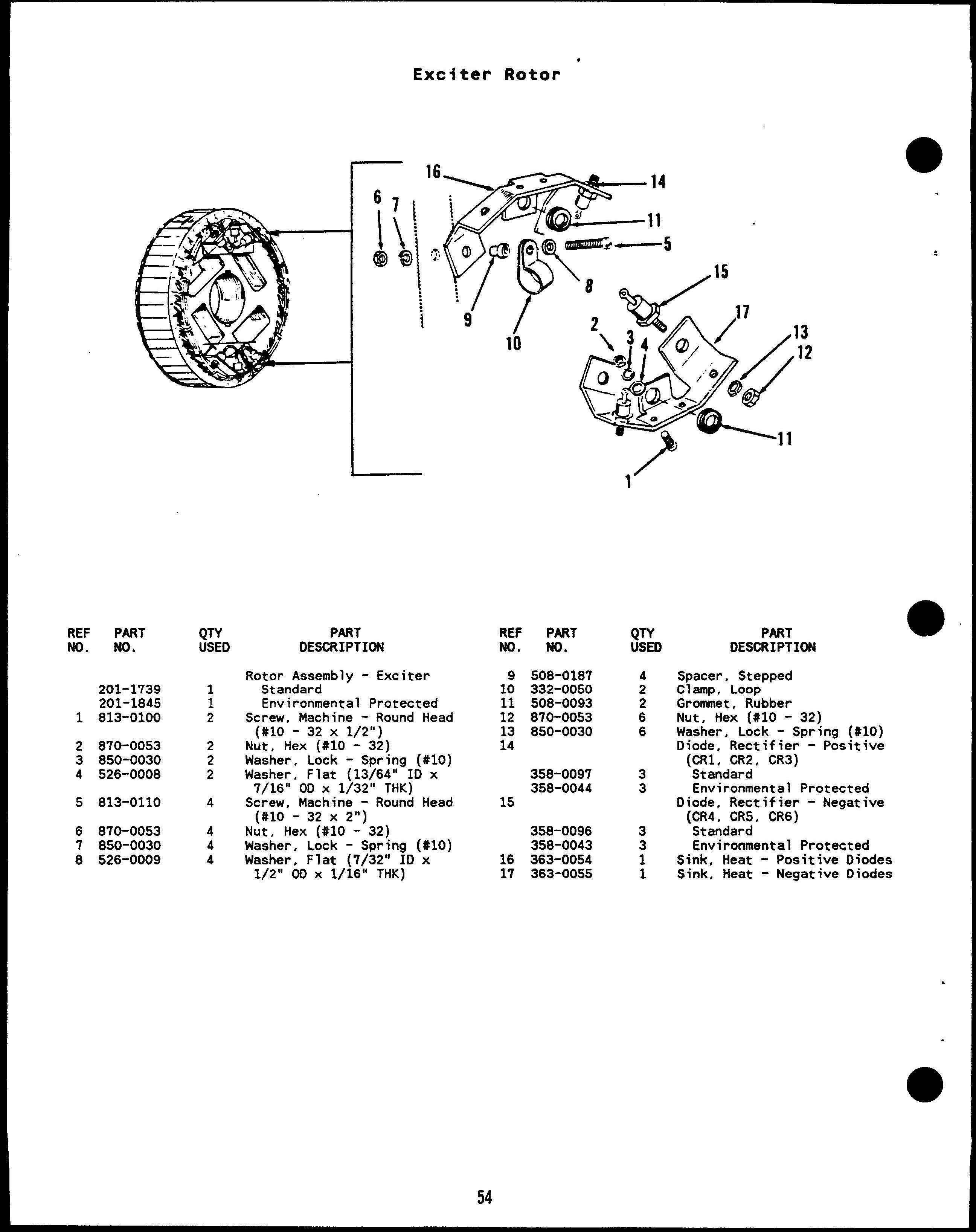
Rotor Assembly - Exciter Standard Environmental Protected Screw, Machine - Round Head (#lo - 32 X 1/2”) Nut, Hex (#10 - 32) Washer, Lock - Spring (#10) Washer, Flat (13/64” ID x 7/16” OD X 1/32” THK) Screw, Machine - Round Head (#lo - 32 X 2“) Nut, Hex (#10 - 32) Washer, Lock - Spring (#10) Washer. Flat (7/32” ID x 1/2” 60 x l/i6”” THK)

PART NO.

yYTY

4 2

508-0187 332-0050 508-0093 870-0053 850-0030

: 6

358-0097 358-0044

3 3

358-0096 358-0043 363-0054 363-0055

3 3 1 1

15

16 17

54

PART DESCRIPTION Spacer, Stepped ClamP, LooP Gronnnet, Rubber Nut, Hex (#10 - 32) Washer, Lock - Spring (#IO) Diode, Rectifier - Positive (CR1, CR2, CR3) Standard Environmental Protected Diode, Rectifier - Negative (CR4 , CR5 , CR6) Standard Environmental Protected Diodes Sink, Heat - Positive Diodes Sink, Heat - Negative


Voltage

REF No.

PART No.

QTY USED

1

813-0112

4

2

526-0140

4

3 4 5 6

850-0030 870-0053 508-0093 305-0526

4 4 2 1

,

.

Suppressor

PART DESCRIPTION

REF ND.

Screw, Machine - Round Head (#lo - 32 X 2-1/2”) Washer, Flat (7/32” ID x 3/8” OD X 3/64” THK) Washer, Lock - Spring (#IO) Nut, Hex (#10 - 32) Grommet, Rubber Suppressor Set, Voltage (Matched Pair)

55

PART ND.

QTY USED

7

526-0140

4

8 9 10 11

850-0030 870-0053 363-0054 363-0055

4 4 1 1

PART DESCRIPTION Washer, Flat (7/32” ID x THK) 3/8” OD X 3/64” Washer, Lock - Spring (#IO) Nut, Hex (#10 - 32) Sink, Heat - Positive Sink, Heat - Positive


Generator

Heater

● *”X,

“\

““”””A-—..—..._ ..= ..*

—.**

N -

\’\

\

REF NO.

PART NO.

QTY USED

1

2

335-0146 335-0147 800-0004

1 1 1

REF No.

PART DESCRIPTION Cable Assembly, Electric ( ;;;l;~s Thermostat )

3 4

240 VAC Screw, Cap - Hex Head - 20 X 5/8”) (1/4

5

PART No. 850-0038 526-0158

333-0059 333-0192

56

QTY USED

:

;

PART DESCRIPTION Washer, Lock - Spring Washer, Flat (17/64” THK) 1“ OD X 1/8” Heater, Electrical 120 VAC, 125 Watt 240 VAC, 200 Watt

(1/4) ID x ,-


Nagnetic ...... ..... . ..---=... ,.-

Pickup

%

6

REF NO.

PART NO.

QTY USED

1

800-0003

2

2 3 4 5 6 7 8 9

850-0040 150-1410 150-1406 868-0011 862-0001 853-0013 150-0723 870-0250

2 1 1 2 2 1 1 1

PART DESCRIPTION

REF No.

Screw, Cap - Hex Head (1/4 - 20X 1/3”) Washer, Lock - Spring (1/4”) Cap, Insulator Sensor, Speed - Magnetic Nut, Hex - Jam (3/4 - 16) Nut, Hex (1/4 - 20) Washer, Lock - ET (1/4) Contact, Electrical Nut, Insulator

57

PART No.

g

PART DESCRIPTION

10 11

301-9402 800-0053

1 1

12 13 14

856-0010 150-0717 526-0077

1 1 1

15 16 17

150-1557 370-4011 854-0031

1 1 1

Bracket, Mounting Screw, Cap - Hex Head (3/8 - 16 X 1-3/4”) Washer, Lock - EIT (3/8) Switch, Overspeed Washer, Flat (13/32” ID x 1-1/4” OD X 1/4” THK) Wheel, Sensor - Speed Spacer, Sleeve Washer, Lock - IT (3/4)


Engine

Control

.

““>. ~. ,...-’

.

,.,,.-

-f/ II

.

I

137

“ /F

/

‘Q

-15

‘s

1

26

22

31


I

.

Engine

● <

REF NO.

PART NO.

$Yo

1

815-0544

24

2

300-2899

1

3

4

300-2903 300-2904 300-2906

: 1

5

300-2856

1

6

300-2863

1

7“

8

300-2808 300-2810 300-2812 321-0270

1 1 1 2

9

321-0231

1

10

321-0094

2

11 12 13 14 15

323-1305 323-1303 323-1309 323-1307 301-8851

1 1 1 1 1

821-0004

4

16

322-0358-02 322-0359-02 322-0360-02

1 1 1

Control

PART DESCRIPTION Screw, Machine - Round Head IT Washer (#6 - 32 x 1/2”) Board Assy, Printed Circuit Time Oelay, Start/Stop (A15) Board Assy, Printed Circuit Magnetic Pickup (A16) Standard (Fixed Sensitivity) Precision (Adj Sensitivity) Printed Circuit Board Assy, Over/Under Volt Sensor (A17) Board Assy, Printed Circuit Relay Assembly - (A13) Printed Circuit Board Assy, Relay Assembly - (A14) Printed Circuit Board Assy, Engine Monitor - (All) (Includes Fuses & Connectors) 2 Light Control 7 Light Control 12 Light Contro’ Fuse, Cartridge - 20 Amp (Fl, F2) Fuse, Cartridge - 15 Amp (F3) Fuse, Cartridge - 5 Amp (F4, F5) Connector - 8 Pin (PI) Connector - 6 Pin (P2) - 13 Pin’(P3) Connector Connector - 12 Pin (P4) Bracket, Mounting - Printed Circuit Board Assembly Screw, Self-Locking - Hex Washer Head (#10 = 32 x 5/16 “ ) Module, Xndicator - Fault (A12) (Includes Connector Housing) 2 Light Control 7 Light Control 12 Light Control

REF NO.

17

PART NO.

(&

815-0385

2

870-0183

2

18

323-1310 323-1302 322-0369-02

19

322-0017

1

20 21 22

322-0361 517-0131 151-0402

1 :

23

308-0785

1

24

308-0784

1

26 27 28 29 30 31 32 33 34 35

301-6257 193-0250 193-0352 193-0351 302-1790 302-0885 193-0330 302-1715 517-0221 322-0052 870-0131

1 3 1 1 1 1

1: 1

: 1 1 1

36

37 38 39 40

301-9055-01 301-9055-02 338-1817 323-1308 323-1302 323-1304 323-1200 323-1306 323-1200

* Parts

included

: 1

1: 1 6 1 8

in

PART DESCRIPTION Screw, Machine - Round Head (#6 - 32 x 1/2”) Nut, Self-Locking - ET Hex Washer Head (86 - 32) Housing, Corm - 13 pin (J3) Contact, Pin Lamp, Incandescent - 1/3 Watt 28 Volts DC Lamp, Incandescent - 28 Volts Oc (0s11) Holder, Lamp Plug, Button Potentiometer - Speed Control (Rll) Switch, Push - Reset/Panel LamP (S11) Switch, Push - Run/Stop/ Remote (S12) Cover, Hole - Switch Resistor, Gauge (R12) Gauge, Pressure - Oil (Mll) (M12) Gauge, Temp - Water Meter, Ampere - DC (M13) Meter, Running Time (M14) Gauge, Temp - Oil (M15) Meter, Tach (M16) Plug, Button ClamP, LooP Nut, Self-Locking - ET Hex Washer Head (#10 - 32) Door, Control 5 Gauge Holes 3 Gauge Holes Harness, Wiring - DC (Includes Connector Housing) Housing, Corm - 12 Pin (J4) Contact, Pin *Housing, Corm - 6 Pin (J2) * Contact, Pin *Housing, Corm - 8 Pin (Jl) * Contact. Pin

Control

To Engine

Wiring

Harness.

.

● 59

I


Generator

Control.

i4

\ 15 4

60


Generator

REF NO.

QTY USED

1

,

338-1818 338-1853 812-0065

1 1 2

2 3 4

332-0607 332-2723 322-0363

: 1

5 6

302-1148

1

302-1757

1

302-1683

1

302-1684

1

7 8

302-1720

9 10

303-0032

11 12 13

PART NO.

14

; 1 1 1 1 1

320-1121 320-1438 303-0261 308-0284 332-0052 870-0131

: 1

406-0334

2

PART DESCRIPTION Harness, Wiring - AC (Includes Terminal Block) Controls With Meters Controls Without Meters Screw, Machine - Round Head (#6 - 32 x 5/8”) Block, Terminal (TB1) Marker Strip, Light, Indicator - Dual (DS21, DS22) Meter, Volt - AC (M21) Meter, Ampere - M22 Single Scale O-75 (Voltage Code 9x) Dual Scale 0-100/200 Amp (Voltage Code 515) 0-150/300 Amp (Voltage Code 15) Meter, Frequency (M23) Meter, Watt (M24) (See Separate Page For Components) Knob Circuit (CB21) Breaker, Without Auxiliary Contacts With Auxiliary Contacts Rheostat (R21) Switch, Rotary (S21) Clamp, Loop Nut, Self-Locking - ET Hex Washer Head (#10 - 32) Clip, Retaining - Turnbutton Fastener

Controi REF NO.

PART NO.

QTY USED

406-0333

2

301-9054-01 301-9054-02 301-9054-03 821-0004

1 1 1 3

307-1987 307-1056 323-0804 815-0544

2 1 2

20

406-0332

2

21

300-2880 815-0544

1 6

22

337-0049 800-0024

1 1

856-0008 508-0051 402-0527 800-0045

1 1 4 4

850-0045 301-8065 821-0010

4 1 2

15 16

17 18 19

23 24

25 26 27

.

61

1

1

PART DESCRIPTION Stud, Fastener - Turnbutton Door, Control 4 Meter Holes 3 Meter Holes No Meter Holes Screw, Self-Locking - Hex Washer Hd (#10 - 32 x 5/16”) Clip, Retaining - Relay Relav, 24 VDC Socket, Relay Screw, Machine - IT Round Washer Hd (#6 - 32 x 1/2”) Receptacle, Turnbutton Fastener Regulator, Voltage (VR21) Screw, Machine - IT Round Washer Hd (#6 - 32 x 1/2”) Strap, Electrical (Ground) Screw, Cap - Hex Head (5/16 - 18 X 1/2”) Washer, Lock - EIT (5/16) Grommet Mount, Vibration Screw, Cap - Hex Head - 18 X 3/8”) (5/16 Washer, Lock - Spring (5/16) Box, Control Screw, Self-Locking - Hex Washer Hd (1/4 - 20 x 1/2”) Transformer Assembly - Current (See Separate Page For Components)


Current

Transfortier

14

/e

Q

Q

3

REF NO.

PART NO.

QTY USED

1

2 3 4 5 6

815-0203

1

871-0010 856-0003 854-0010 526-0049

3

813-0110

6

854-0010 302-0235 302-0236 302-0253

1 2 2

6 3 3 6

PART DESCRIPTION Terminal Assembly, Ground (Includes Parts Marked *) * Screw, Machine - Round Head * x7/8”) Brass (#10 -32 * Nut, Hex - Brass (#10 - 32) * Washer, Lock - EIT (#IO) * Washer, Lock - IT (#IO) * Washer, Flat - Brass (13/64” ID X 7/32” OD X 1/32” THK) Screw, Machine - Round Head (#lo - 32 X 2“) Washer, Lock - IT (#10) Clamp, Upper Clamp, Lower Shim

PART NO.

REF NO. 7

302-1365

3

8 9

302-0729 813-0100

1 6

10

526-0008

6

11 12 13 14

856-0003 870-0053 302-0764

6 6 1

302-0865

3

302-0866

3

*

62

Parts

included

PART DESCRIPTI~

yYD

in

Transformer, Current - Ratio 75/5 (Voltage Code 9X) Bracket, Mounting - Transformer Screw, Machine - Round Head (#lo - 32 X 1/2”) Washer, Flat (13/64” 10 x 7/16” 00 X 1/32” THK) Washer, Lock - EIT (#IO) Nut, Hex (#10 - 32) Bracket, Mounting - Transformer Transformer, Current Ratio 300/5 (Voltage Code 515) Ratio 250/5 (Voltage Code 15) Ground

Terminal

Assembly.

t

.


.

Mattmeter

6

.

8 \

1 0

REF NO. c

1 2 3 4 5 6

PART NO.

QTY USED

821-0017 850-0045 862-0014 860-0008 856-0002

2 2 2 8 16

302-1082 302-1083

1 1

PART DESCRIPTIW

REF No.

Screw, Lock (5/16 - 18 x 1/2”) Washer, Lock (5/16) Nut, Hex (5/16 - 18) Nut, Hex (#8 - 32) Washer, Lock - EIT (#8) Transducer, Watts 3 Phase, 60 Hertz 3 Phase, 50 Hertz

QTY USED

PART DESCRIPTION Mount, Shock 8racket, Mounting - Watts Transducer Harness, Wiring - Watts Transducer Meter. Watt - OC Dial, Wattmeter

7 8

402-0354 301-6987

4 1

9

338-1936

1

302-1722 302-1721-03

1 1

10 11

63

PART m.


Control

Housing

,11

&\

+----10

PART NO.

y&

1

821-0010

8

2 3

234-0370 815-0350

1 18

4 5

301-3156 821-0010

3 4

6 7

234-0361 821-0018

1 6

8

856-0006

1

REF NO.

PART DESCRIPTION Screw, Washer Grille, Screw, (#lo Panel, Screw, Washer Wrapper, Screw, Washer Washer,

REF NO.

Self-Locking - Hex Hd (1/4 - 20 x 1/2”) Inlet Air - Generator Tap - Hex Washer Head 32 X 3/8”) Access Self-Locking - Hex Hd (1/4 - 20 x 1/2”) Bell - End Self-Locking - Hex Hd (1/4 - 20 x 5/8’1) Lock - EIT (1/4)

64

PART NO.

QTY

USED

9

526-0018

5

10 11 12

870-0212 301-3155

6 1

13

508-0203 508-0051 821-0010

1 1 1

14

821-0014

8

15

301-31s4

1

PART DESCRIPTION Washer, Flat (17/64” ID x 5/8” 00 X 1/16” THK) Nut, Hex (1/4 - 20) Housing, Box - Control Grommet Used Thru October 1984 Used 8eginning November 1984 Screw, Self-Locking - Hex Washer Hd (1/4 - 20 x 1/2”) Screw, Self-Locking - Hex Washer Hd (5/16 - 18 x 1/2”) Saddle, 80X - Control


Control

Heater

)

REF NO.

PART NO.

QTY USED

1

870-0183

2

2 3 4 5

301-1886 860-0006 854-0006 812-0070

1 2 2 2

6

309-0128

1

REF NO.

PART DESCRIPTION Nut, Self-Locking - Hex ET (#6 -32) Cover, Thermostat Nut, Hex (#6 - 32) Washer, Lock - IT (#6) Screw, Machine - Round Head (#6 -32 X 1-1/4) Thermostat, Adjustable

65

PART ND.

QTY USED

7

800-0034

2

8

526-0113

2

9 10 11 12

333-0151 130-1107 870-0257 335-0161

1 2 ?

PART DESCRIPTION Screw, Cap - Hex Head (5/16 18 X 2-1/4”) Washer, Flat (11/32” 10 x 1“ 00 X 3/32” THK) Heater, Electrical Spacer, Sleeve Nut, Self-Locking (5/16 - 18) Cable, Electrical


Circuit

(Spec

Breaker A)

.

a

1 <,

\

8

66

‘9


Circuit

a

REF No.

PART NO.

QTY USED

1

813-0096

48

2 3

301-9406

1

301-9259 301-9458 301-9403 301-9405 301-9255 301-9409 301-9408 301-9407 301-9256

1 : 1 2 2 2 2 1

301-9459

1

301-9460

1

898-0863 898-0865 898-0875 898-0869 898-1112

1 1 : 1

13

898-0974 898-0976 800-0028

: 5

14

526-0022

10

15 16 17

850-0045 862-0015 812-0156

5 5 4

18 19 20

850-0040 850-0030

4 6

e

4 5 6 7 8 1:

11

12

320-1061 320-1062 320-0344 320-1409 320-0359 320-1411 320-0420

320-0384 320-0416 320-0414 320-0417 320-1408 320-1407 320-1404 320-0411 320-0379 320-0418 320-0412 320-0380 320-1405 320-1049 320-0446 320-0346 320-0425

: i 1 1 1 1 1 1 1 1 1 1 1 i : 1 1 1 1 1

(Spec

PART DESCRIPTION

Breaker A) REF No.

Screw, Machine - Round Head (#lo - 32 X 1/4”) Cover, Top Cover, 8reaker - Circuit 5B* x 3-1/4” 8reaker Hole 3-1/4” x 1-1/2” 8reaker Hole Panel, Front Wrapper, Enclosure Cover, Access - Side Panel, Access - 8ottom Panel, End Panel, End 8racket, Mounting - Circuit 8reaker Used on Circuit Breakers 241 Volts and Up Used on Circuit Breakers 240 Volts and Below Sleeving, Shrinkable 0.75” ID 1.00” ID 1.S0” ID 2.00” ID 3.00” ID Sleeving, Fiberglass 0.75” ID 1.00” ID Screw, Cap - Hex Head (S/16 18 X l“) Washer, Flat (21/64” ID x 9/16” OD X 1/16” THK) Washer, Lock - Spring (5/16) Nut, Hex (5/16 - 18) Screw, Machine - Round Head (1/4 - 20 x 1-1/2”) Washer, Lock - Spring (1/4) Washer, Lock (#10) 8reaker, Circuit Two Pole 125 Amp, 240 VAC 150 Amp, 240 VAC 175 Amp, 240 VAC 200 Amp, 240 VAC 225 Amp, 240 VAC 250 Amp, 240 VAC 300 Amp, 240 VAC Three Pole 60 Amp, 480 VAC 60 Amp, 600 VAC 70 Amp, 480 VAC 70 Amp, 600 VAC 80 Amp, 240 VAC 80 Amp, 480 VAC 80 Amp, 600 VAC 90 Amp, 240 VAC 90 Amp, 480 VAC 90 Amp, 600 VAC 100 Amp, 240 VAC 100 Amp, 480 VAC 100 Amp, 600 VAC 125 Amp, 240 VAC 125 Amp, 480/600 VAC 150 Amp, 240 VAC 150 Amp, 480/600 VAC

PART No.

PART DESCRIPTION

320-0347 320-0426 320-0348 320-0447 320-0349 320-0269 320-0422 320-0445 320-0423 320-0401

175 Amp, 240 175 @p, 480/ 200 Amp, 240 200 Amp, 480/ 225 Amp, 240 225 Amp, 480/ 250 Amp, 240 250 Amp, 480/ 300 Amp, 240 300 Amp, 480/ Three Pole with 90 Amp, 480 V 100 Amp, 480 125 Amp, 600 150 Amp, 480/ 175 Amp, 240 200 Amp, 480/ 225 Amp, 240 250 Amp, 480/ 300 hp. 240 300 Amp, 480/ Three Pole with Shunt Trip 125 Amp, 600 150 Amp, 600 175 hip, 600 200 Amp, 600 300 Amp, 600 Three Pole with Shunt Trip 100 ~p, 480 100 Amp, 600 125 Amp, 600 150 Amp, 600 175 Amp, 600 200 limp, 600 225 Amp, 600 300 Amp, 600 Three Pole with Shunt Trip 125 Amp, 600 150 Amp, 600 175 Amp, 600 200 Amp, 600 225 Amp, 600 250 Amp, 600 300 Amp, 600 Three Pole with Shunt Trip 300 Amp, 600 Two Pole with 1 Shunt Trip anc 200 Amp, 240 300 Amp, 240 Three Pole witt Volt Shunt Tri Contacts 90 Amp, 480 \ 150 Amp, 240 150 Amp, 600 200 Amp, 240 225 Amp, 240 250 Amp, 600

320-1231 320-1421 320-1428 320-0738 320-0700 320-0988 320-1222 320-0975 320-0620 320-0300

320-0556 320-0658 320-0453 320-0392 320-0370

320-1427 320-1432 320-1430 320-0688 320-0731 320-0S29 320-1433 320-0438

320-0238 320-0315 320-0215 320-0573 320-0285 320-0708 320-0268

320-0331

320-1144 320-1424

320-1300 320-0772 320-1422 320-1145 320-1035 320-1429

67


Circuit (Spec

Breaker B)

.

,.

<

● 68


Circuit (Spec

● L

REF NO. 1 2 3

4 5 6 7 8

PART No. 815-0350

QTV USED 52

301-9406

1

301-9720

1

301-9721

1

301-9403 301-9405 301-9255 301-9409 301-9408 301-9407

1 1 2 : 2

1: 301-9716

1

301-9722

1

11

12

898-0863 898-0865 898-0867 898-0869 98-2304

13

800-0028

5

14

526-0022

10

15 16 17

850-0045 B62-0015 812-0156

5 5 4

850-0040 332-1445 813-0096

4 3 6

850-0030

6

320-1512-06 320-1512-07 320-1512-08 320-1512-09 320-1512-10 320-1513-06 320-1513-07

1

320-1458-24 320-1458-41 320-1458-25 320-1458-42 320-1458-12 320-1458-26 320-1458-43 320-1458-13 320-1458-27 320-1458-44 320-1458-14 320-1458-28 320-1458-45 320-1458-30 320-1458-47 320-1458-31 320-145B-48 320-1459-OB 320-1459-09

1 1 1

21 22

: : 1

: : 1 1

: : 1 1 1 1 1 1 i : 1 1

PART DESCRIPTION

Breaker B) REF NO.

Screw, Self-Locking - Hex Washer Hd (#10 - 32 x 3/8”) Cover, Top Cover, Breaker - Circuit For use with 225 Amp Circuit Breakers and below For use with 250 Amp Circuit Breakers and above Panel, Front Wrapper, Enclosure Cover, Access - Side Panel, Access - Bottom Panel, End Panel, End Bracket, Mounting - Circuit Breaker Used on Circuit Breakers 600 Amps and below Used on Circuit Breakers 700 Amps and above Sleeving, Shrinkable 0.75” 10 1.00” ID 1.50” ID 2.00” ID Silkscreen, Breaker - Circuit (Warning) Screw, Cap - Hex Head (5/16 18 X l“) Washer, Flat (21/64” ID x 9/16” 00 X 1/16” THK) Washer, Lock L Spring’(5/16) Nut, Hex (5/16 - 18) Screw, Machine - Round Head ( 1/4 - 20 x 1-1/2”) Washer, Lock - Spring (1/4) Tie, Cable Screw, Machine - Round Head (#10 -32 X 1/4”) Washer, Lock (#10) Breaker, Circuit Two Pole 125 Amp, 600 VAC 150 Amp, 600 VAC 175 Amp, 600 VAC 200 Amp, 600 VAC 225 Amp, 600 VAC 250 Amp, 600 VAC 300 Amp, 600 VAC Three Pole 60 Amp, 480 VAC 60 Amp, 600 VAC 70 Amp, 480 VAC 70 Amp, 600 VAC 80 Amp, 240 VAC 80 Amp, 480 VAC 80 Amp, 600 VAC 90 Amp, 240 VAC 90 Amp, 480 VAC 90 Amp, 600 VAC 100 Amp, 240 VAC 100 tip, 480 VAC 100 Amp, 600 VAC 125 Amp, 480 VAC 125 Amp, 600 VAC 150 Amp, 480 VAC 150 Amp, 600 VAC 175 Amp, 600 VAC 200 Amp, 600 VAC

PART NO.

QTV USED

320-1459-10 320-1460-06 320-1460-07

1

320-1515-06 320-1515-07 320-1515-08 320-1515-09 320-1515-10 320-1516-06 320-1516-07 320-1462-24 320-1462-41 320-1462-25 320-1462-42 320-1462-12 320-1462-26 320-1462-43 320-1462-13 320-1462-27 320-1462-44 320-1462-14 320-1462-28 320-1462-45 320-1462-30 320-1462-47 320-1462-31 320-1462-48 320-1463-08 320-1463-09 320-1463-10 320-1464-06 320-1464-07

1 1 1

1 1 1

1 1 1

1 1 1 1 1 1 1 1

320-1522-07

1

320-1524-08

1

320-1466-47 320-1466-48 320-1467-08 320-1467-09 320-1468-07

1 1 1 1 1

320-1470-26 320-1470-28 320-1470-47 320-1470-48 320-1471-08 320-1471-09 320-1471-10 320-1472-06 320-1472-07

69

1 1

1 1 1

1 1 1 1

320-1474-47 320-1474-48 320-1475-09 320-1475-10 320-1476-06 320-1476-07

1 1 1 1 1 1

320-1484-07

1

PART DESCRIPTION 225 Amp, 600 VAC 250 Amp, 600 VAC 300 Amp, 600 VAC Two Pole with Aux Contacts 125 Amp, 600 VAC 150 ~p, 600 VAC 175 Amp, 600 VAC 200 Amp, 600 VAC 225 Amp, 600 VAC 250 Amp, 600 VAC 300 Amp, 600 VAC Three Pole with Aux Contact 60 Amp, 480 VAC 60 Amp, 600 VAC 70 AmP, 480 VAC 70 Amp, 600 VAC 80 Amp, 240 VAC 80 Amp, 480 VAC 80 Amp, 600 VAC 90 Amp, 240 VAC 90 Amp, 480 VAC 90 Amp, 600 VAC 100 Amp, 240 VAC 100 AITIp, 480 VAC 100 Amp, 600 VAC 125 Amp, 480 VAC 125 Amp, 600 VAC 150 Amp, 480 VAC 150 Amp, 600 VAC 175 Amp. 600 VAC 200 Amp, 600 VAC 225 tip, 600 VAC 250 Amp, 600 VAC 300 Amp, 600 VAC Two Pole with 24 Volt Shunt Trip 300 Amp, 600 VAC Two Pole with 120 Volt Shunt Trip 175 Amp, 600 VAC Three Pole with 12 Volt Shunt Trip 125 Amp, 600 VAC 150 Amp, 600 VAC 175 Amp, 600 VAC 200 Amp, 600 VAC 300 Amp, 600 VAC Three Pole with 24 Volt Shunt Trip 80 Amp, 480 VAC 100 Amp, 480 VAC 125 Amp, 600 VAC 150 Amp, 600 VAC 175 Amp, 600 VAC 200 Amp, 600 VAC 225 Amp. 600 VAC 250 limp, 600 VAC 300 Amp, 600 VAC Three Pole with 120 Volt Shunt Trip 125 Amp, 600 VAC 150 Amp, 600 VAC 200 Amp, 600 VAC 225 Amp, 600 VAC 250 Amp, 600 VAC 300 AIllp, 600 VAC Three Pole with 480 Volt Shunt Trip 300 Amp, 600 VAC


Circuit Breaker (Spec B) REF NO.

PART NO.

320-1536-09

320-1486-27 320-1487-07 320-1487-10

QTV USED

1

1 1 1

PART DESCRIPTION

REF NO.

Two Pole with 24 Volt Shunt Trip & Auxiliary Contacts 200 Amp, 600 VAC Three Pole with 12 Volt Shunt Trip & Axuiliary Contacts 90 Amp, 480 VAC 150 hip, 600 VAC 225 Amp, 600 VAC

PART NO.

320-1490-45 320-1491-09 320-1491-10 320-1492-06 320-1492-07

70

QTV USED

: : 1

PART DESCRIPTION Three Pole Shunt Trip Contacts 100 Amp, 200 h“p, 225 Amp, 250 Amp, 300 Amp,

with 24 Volt & Auxiliary 600 600 600 600 600

VAC VAC VAC VAC VAC

● .

f


ONAN DVA 42.0DVA 42KW Diesel Genset Parts Manual - LAST PAGE

Parts Manual ONAN DVA 42.0DVA 42KW Diesel GenSet

• Engine Parts contact: Phone 269 673 1638 Email: engineparts2@gmail.com www.Diesel-Generator-Engine-Parts.com

• --

LAST PAGE


Turn static files into dynamic content formats.

Create a flipbook
Issuu converts static files into: digital portfolios, online yearbooks, online catalogs, digital photo albums and more. Sign up and create your flipbook.