

Engine Parts contact: Phone 269 673 1638
Email: engineparts2@gmail.com www.Diesel-Generator-Engine-Parts.com

Engine Parts contact: Phone 269 673 1638
Email: engineparts2@gmail.com www.Diesel-Generator-Engine-Parts.com
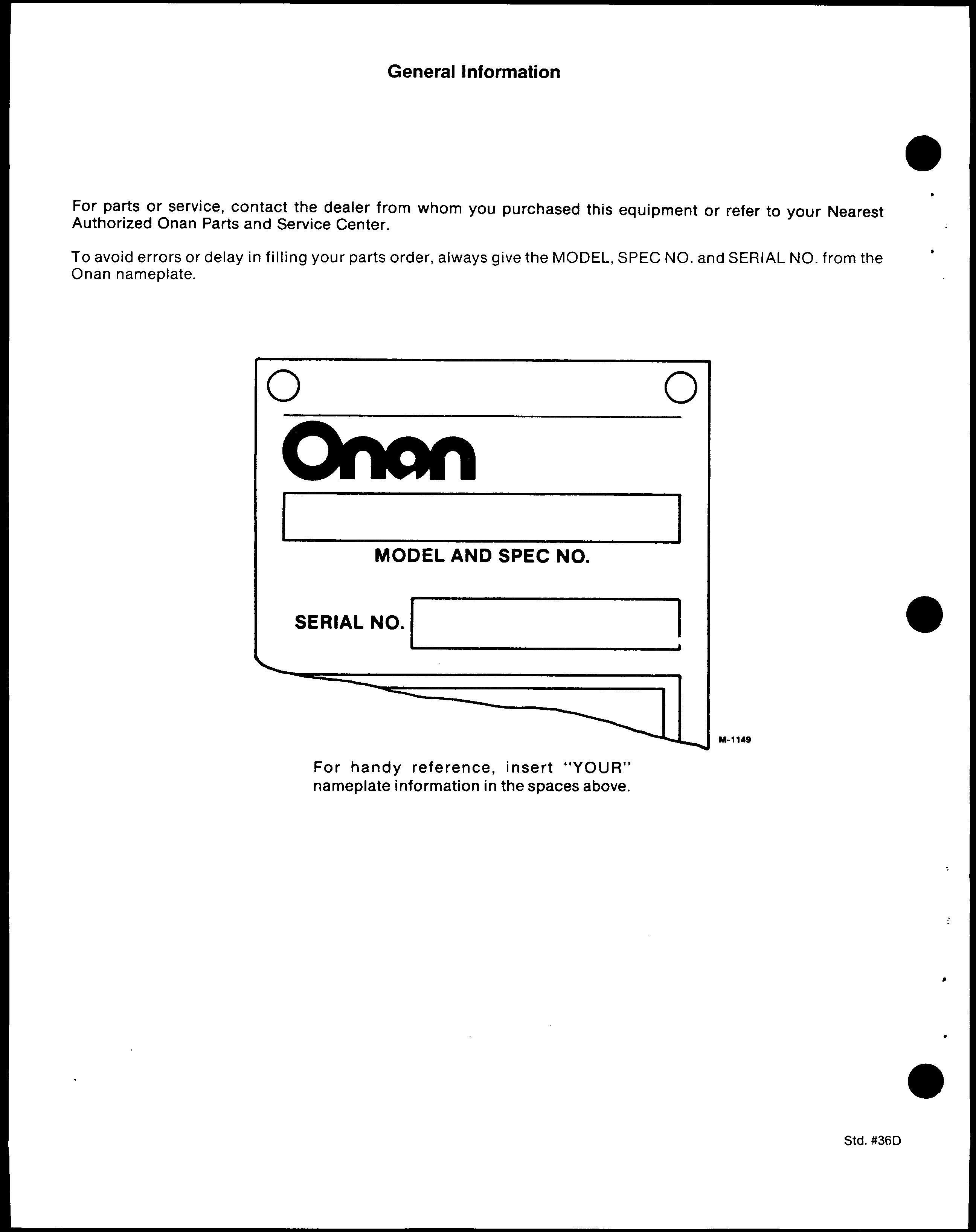
For parts or service, contact the dealer from whom you purchased this equipment or refer to your Nearest Authorized Onan Parts and Service Center.
To avoid errors or delay in filling your parts order, always give the MODEL, SPEC NO. and SERIAL NO. from the Onan nameplate.
For handy reference, insert “YOUR” nameplate information in the spaces above.
Read and obse~e these safety precautions when using or working on electric generators, engines and related equipment. AiSOread and follow the literature provided with the equipment.
proper operation and maintenance are critical to performance and safety. Electricity, fuel, exhaust, moving parts and batteries present hazards that can cause severe personal injury or death.
Fire, explosion, and personal injwy can result from improper practices.
Used engine oil, and benzene and lead, found in some gasoline, have been identified by government agencies as causing cancer or reproductive toxicity. When checking, draining or adding fuel or oil, do not ingest, breathe the fumes, or contact gasoline or used oil.
Do not fill tanks with engine running. Do not smoke around the area. wipe up oil or fuel spills. Do not leave rags in engine compartment or on equipment. Keep this and surrounding area clean.
Inspect fuel system before each operation and periodically while running.
Equip fuel supply with a positive fuel shutoff.
Do not store ortransportequipment with fuel intank.
Keep an ABGrated fire exthguisheraveilable near equipment and adjacent areas for use on ail types of fires except alcohol.
Unless provided with equipment or noted otherwise in installation manual, fuel lines must be copper or steel, secured, free of leaks and separated or shielded from electrical wking.
Use approved, non-conductive flexible fuel hose for fuel wnnections. Do not use mppertubing as affexible connection. It vdll work-harden and break.
Engine exhaust contains cation monoxide (CO), an odofless, invisible, poisonous gas. Learn the symptoms of CO poisoning.
. Never sleep in a vessel, vehicle, or room with agenset or engine running unless the area is equipped with an operating CO detector with an audible alarm.
Each time the engine orgenset is started, or at least every day, thoroughly inspect the exhaust system. Shut down the unit and repair leaks immediately.
Warning Engine exhaust is known to the State of California to cause cancer, birth defects and other reproductive harm.
Make sure exhaust is propedy venfi/ated.
Vessel bilge must have an operating power exhaust.
Vehicle exhaust system must extend beyond vehicle perimeter and not near windows, doors or vents.
Do not use engine or genset cooling air to heat an area.
Do not operate engine/genset in enclosed area without ample fresh air ventilation.
Expel exhaust away “from enclosed, sheltered, or occupied areas.
Make sure exhaust system components are securefy fastened and not warped.
●
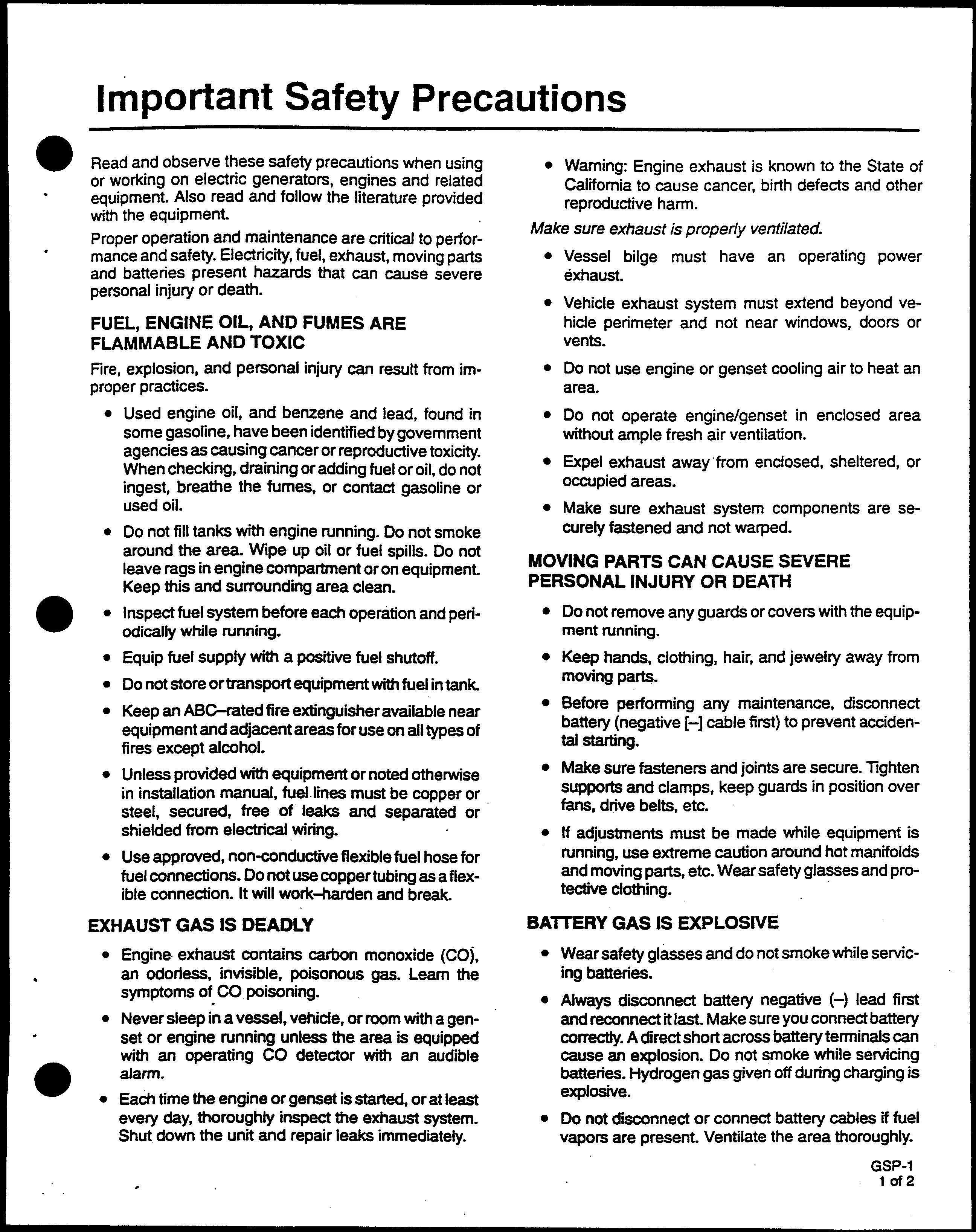
Do not remove any guards or covers with the equipment running.
Keep hands, clothing, hair, and jewelry away from moving parts.
Before P&forming any maintenance, disconnect battery (negative [-] cable first) to prevent accidental starting.
Make sure fasteners and joints are secure. Tghten supports and clamps, keep guards in position over fans, ddve belts, etc.
If adjustments must be made while equipment is running, use extreme caution around hot manifolds and moving parts, etc. Wear safety glasses and protective dothing.
● Wear safety glasses and do not smoke while servicing batteries.
Always d~nnect battety negative (-) lead first and reconnect itlast. Make sure you connect battery correctly. A direct short across battety terminafs can cause an explosion. Do not smoke while servicing batteries. Hydrogen gas given off during charging is explosive.
Do not d~nnect or connect battery cables if fuel vapors are present. Ventilate the area thoroughly.
DO NOT OPERATE IN FLAMMABLE AND EXPLOSIVE ENVIRONMENTS
Flammable vapor can be ignited by equipment operation or cause a diesel engine to overspeed and become diffiCuitto stop, resulting in possible fire, explosion, severe personal injury and death. DOnot operate diesel equip ment where a flammable vapor environment can be created by fuel spill, leak, etc.,unless equipped with anautomatic safety device to block the air intake and stop the engine.
. Hot coolant is under pressure. Do not loosen the coolant pressure cap while the engine is hot. Letthe engine cool before opening the pressure cap.
ELECTRICAL SHOCK CAN CAUSE SEVERE PERSONAL INJURY OR DEATH
●
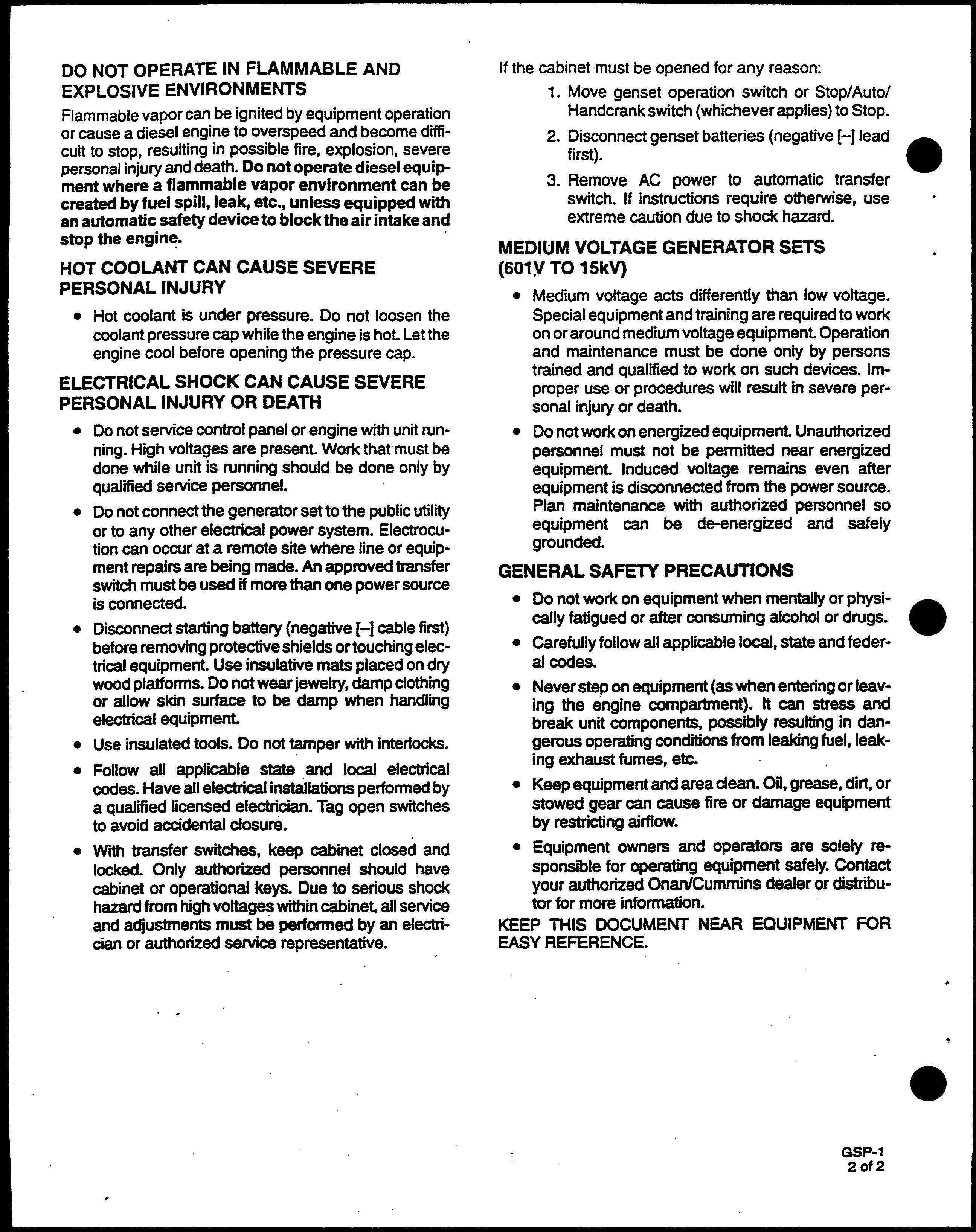
If the cabinet must be opened for any reason:
3. Move genset operation svdch or Stop/Auto/ Handcrankswitch (whichever applies) to Stop. Disconnect genset batteries (negative [-] lead first).
Remove AC Dower to automatic transfer switch. If instr&tions require otherwise, use extreme caution due to shock hazard.
●
Medium voltage acts dfierently than low voltage. Special equipment and training are required to work on or around medium voltage equipment. Operation and maintenance must be done only by persons trained and qualiied to work on such devices, improper use or procedures w.11result in severe personal injury or death.
●
●
●
●
Do not connect the generator set to the public utility or to any other electrical power system. Electrocution can occur at a remote site where line or equipment repairs are being made. An approved transfer switch must be used if more than one power source is connected.
Disconnect starting battery (negative [-] cable first) before removing protective shields ortouching electrical equipment. Use insulative mats placed on dry wood platforms. Do not wear jewelty, damp clothing or allow skin surface to be damp when handling electrical equipment.
Use insulated toots. Do not tamper with interlocks. Follow all applicable state and local electrical codes. Have all electrical installations performed by a qualiied licensed electrician. Tag open switches to avoid accidental closure.
● Do not service control panel or engine with unit running. High voltages are present. Work that must be done while unit is funning should be done only by quahd service personnel.
Wti transfer switches, keep cabhet closed and locked. Only atiofized personnel should have catinet or operationalkeys. Dueto seniousshock hazard from high voltages within cabinet all service and adjustments must be performed by an electrician or authorized service representative.
Do not work on energized equipment. Unauthorized personnel must not be permitted near energized equipment. Induced voltage remains even after equipment is disconnected from the power source. Plan maintenance with authorized personnel so equipment can be de-energized and safely grounded.
●
Do not work on equipment when mentally or physically fatigued or after consuming alcohol or drugs. Carefully follow all applicable local, state and federal codes.
Never step on equipment (as when entering or leaving the engine compartment). It can stress and break unit components, possibly resulting in dangerous operating condtions from leaking fuel, leaking exhaust fumes, etc.
Keep equipment and area dean. Oil, grease, dirt or stowed gear can cause fire or damage equipment by restricting aitiow.
Equipment owners and operators are solely responsible for operating equipment safely. Contact your authorized Onan/Cummins dealer or distributor for more information.
KEEP THIS DOCUMENT NEAR EQUIPMENT FOR EASY REFERENCE.
aActuator, Governor 38
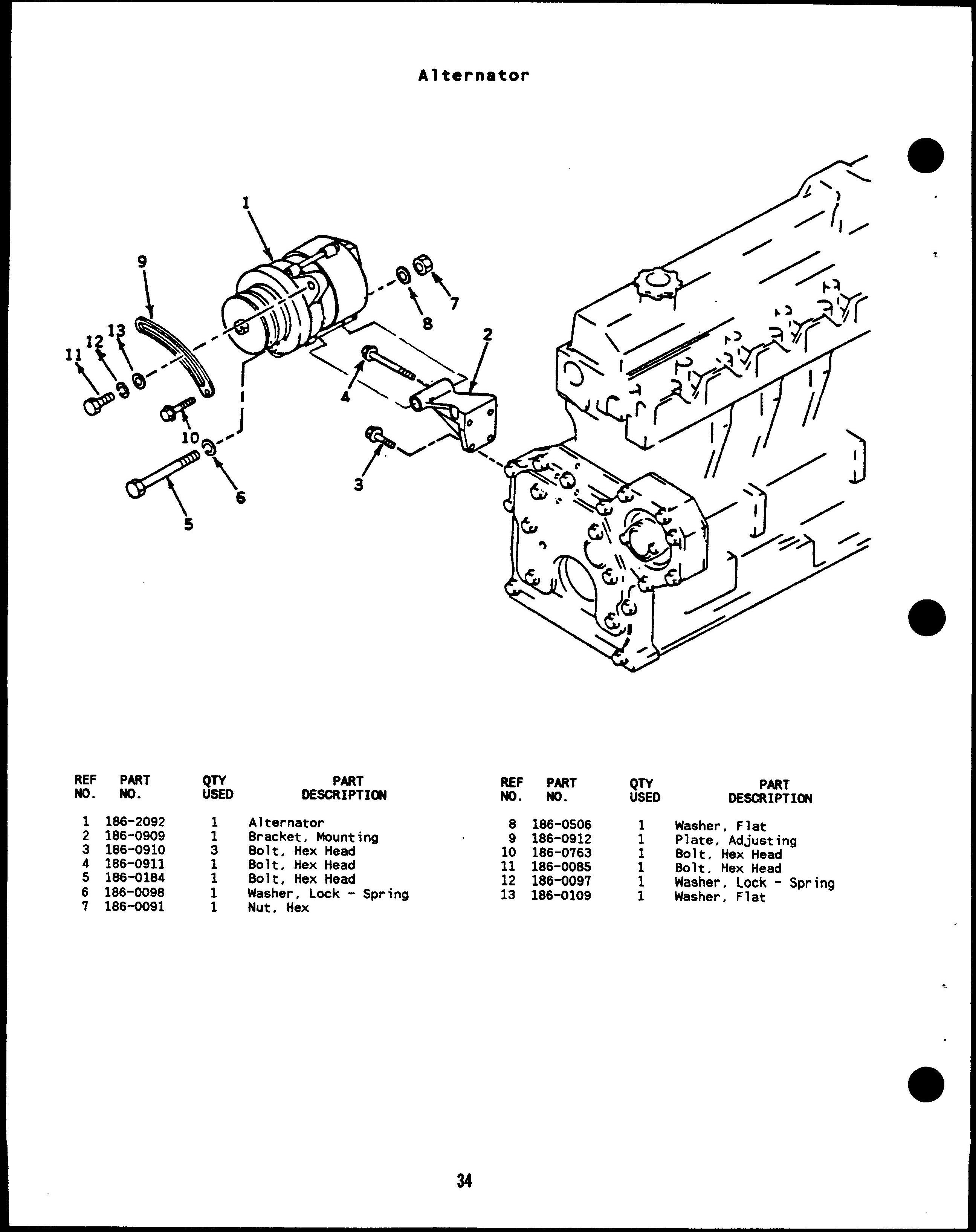
Alternator 34
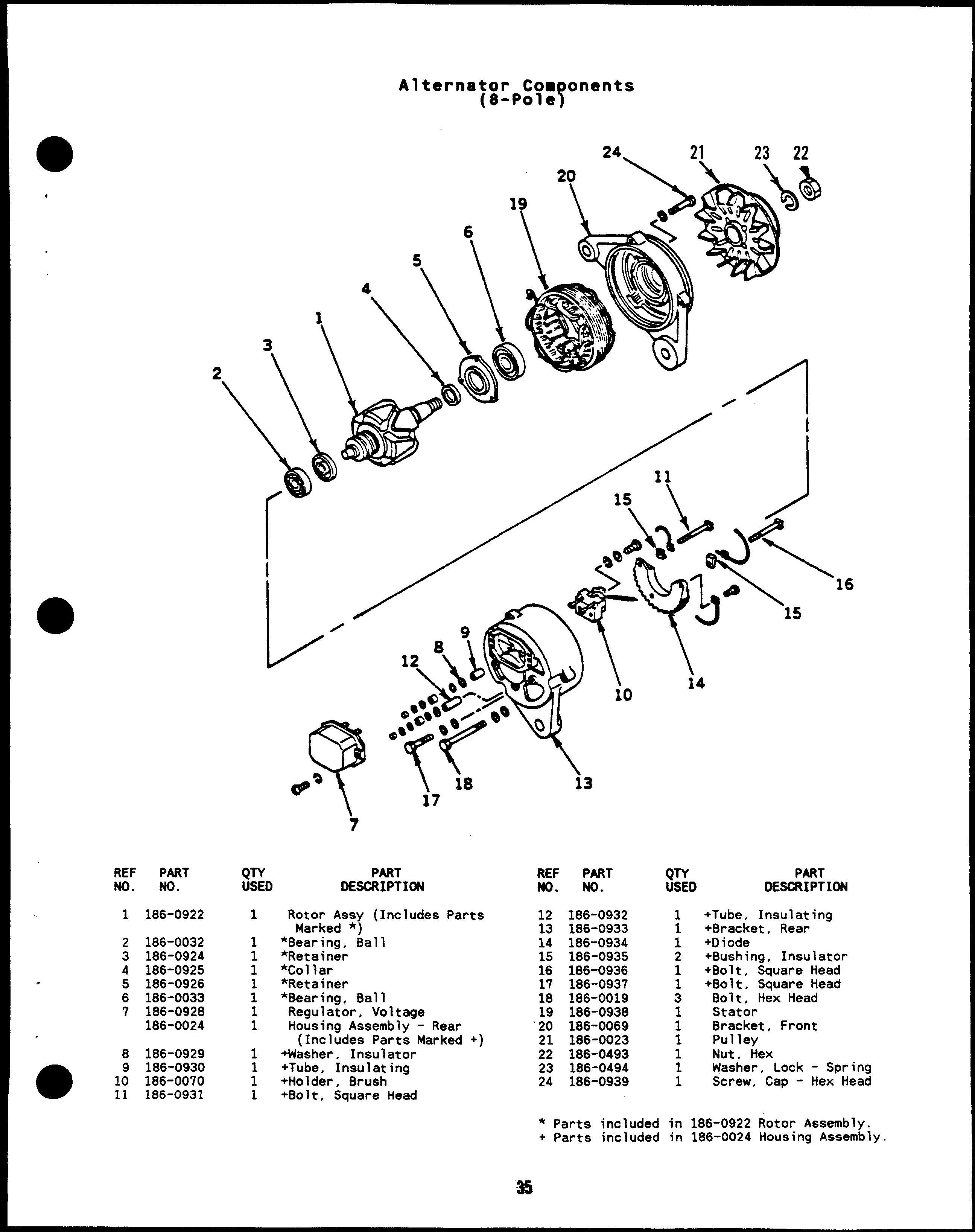
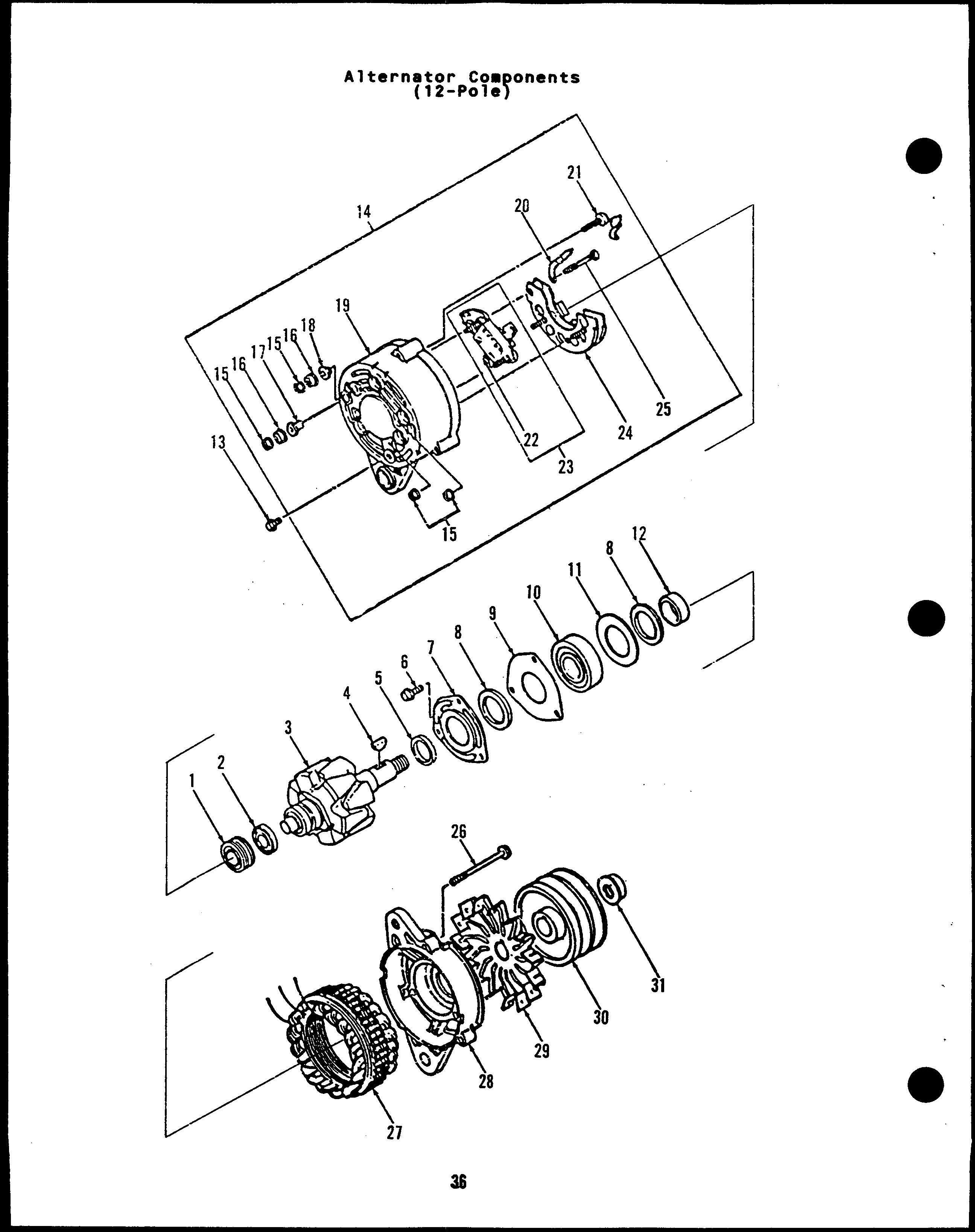
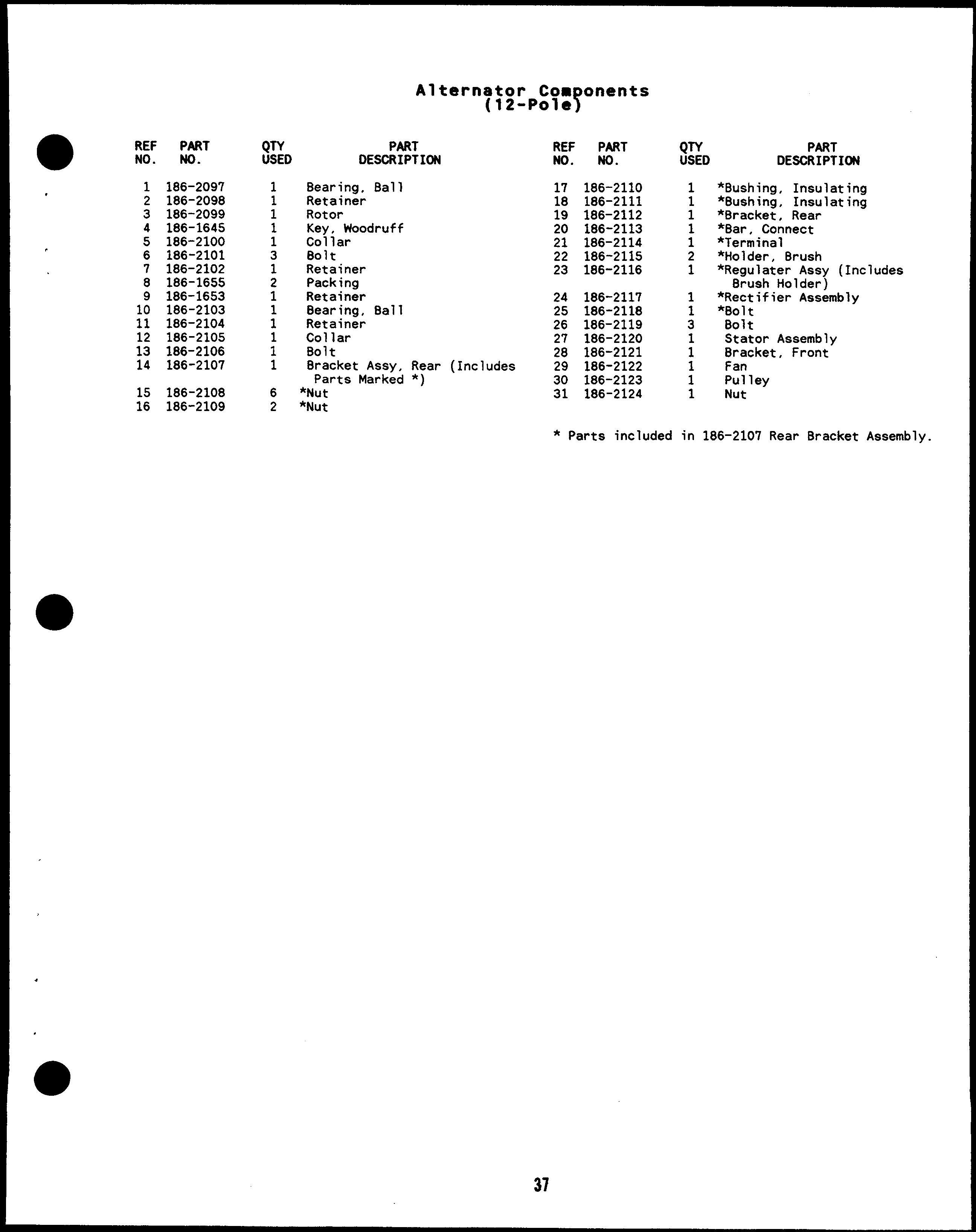
Alternator - Components 35, 36
Armature, Starter 32
Bearing, Camshaft 8
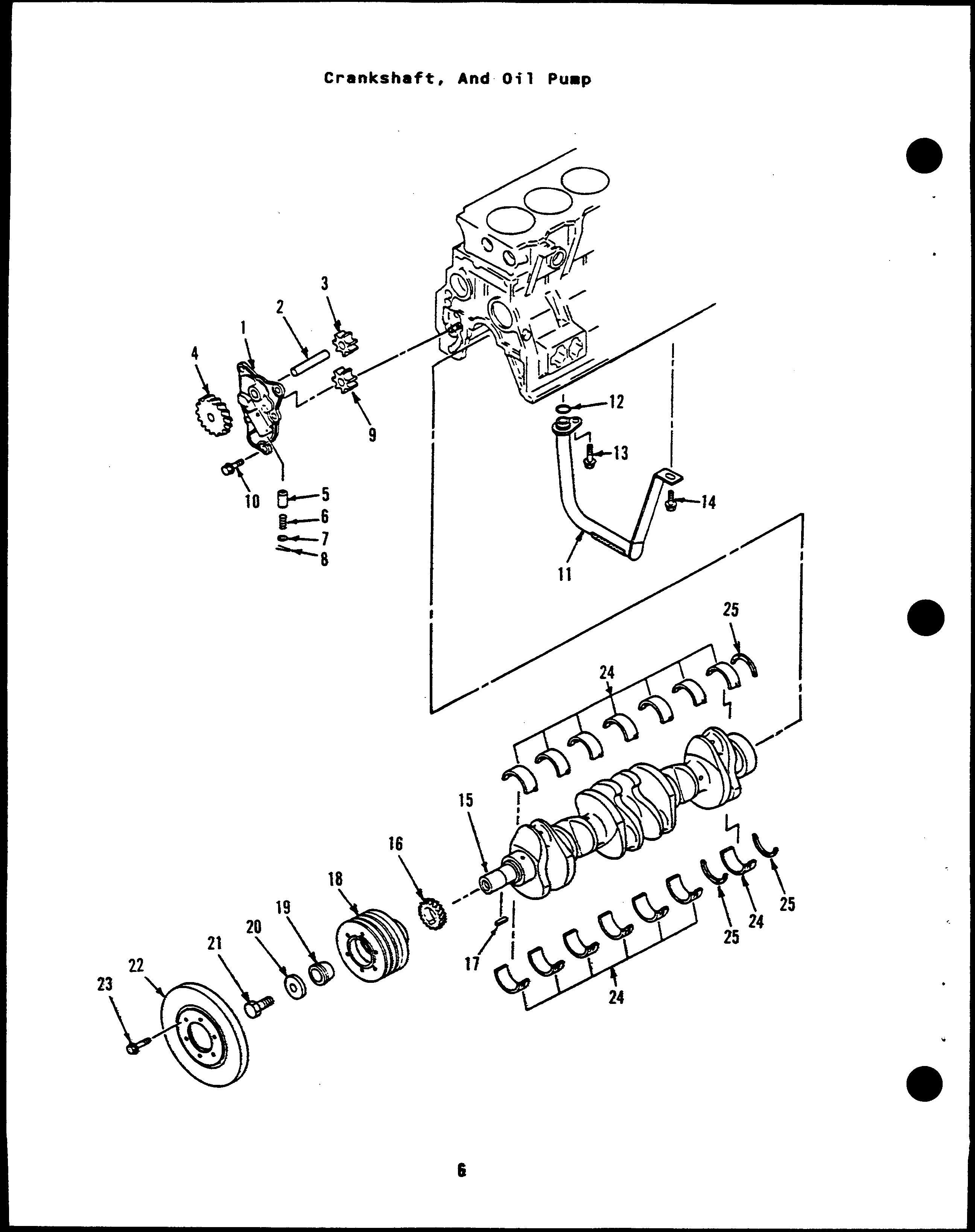
Bearing, Crankshaft 6
Bearing, Rod - Connecting
Bell, End - Generator 54, 5:
Belt Set, Drive - V 39
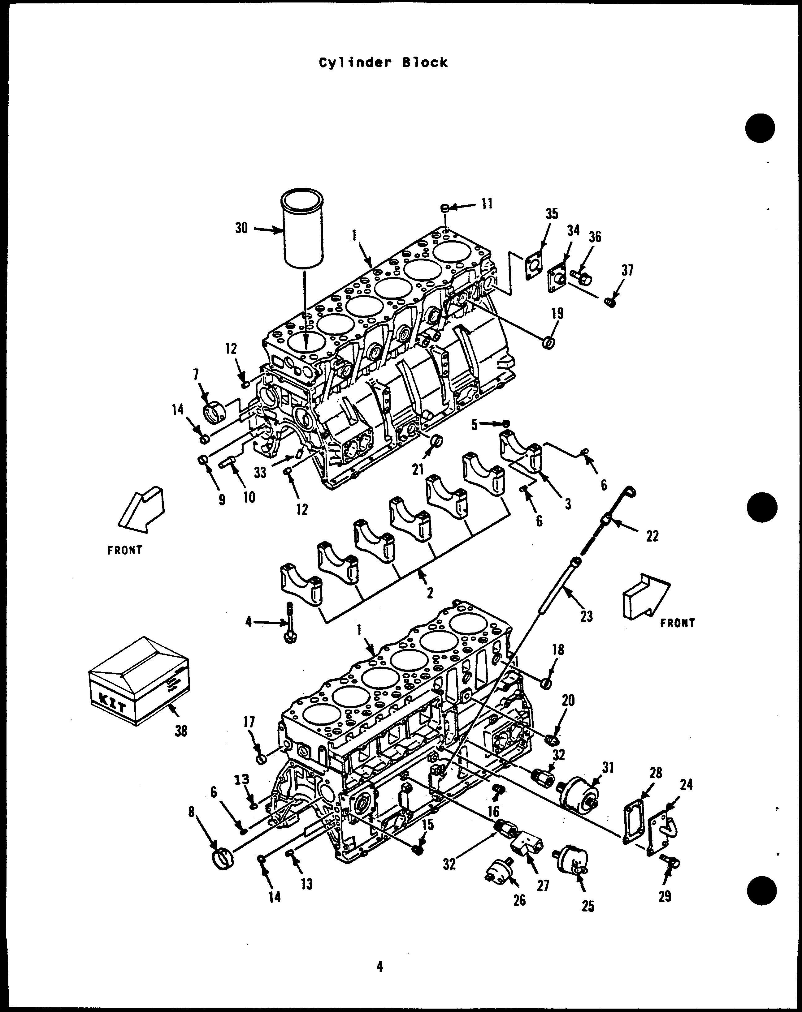
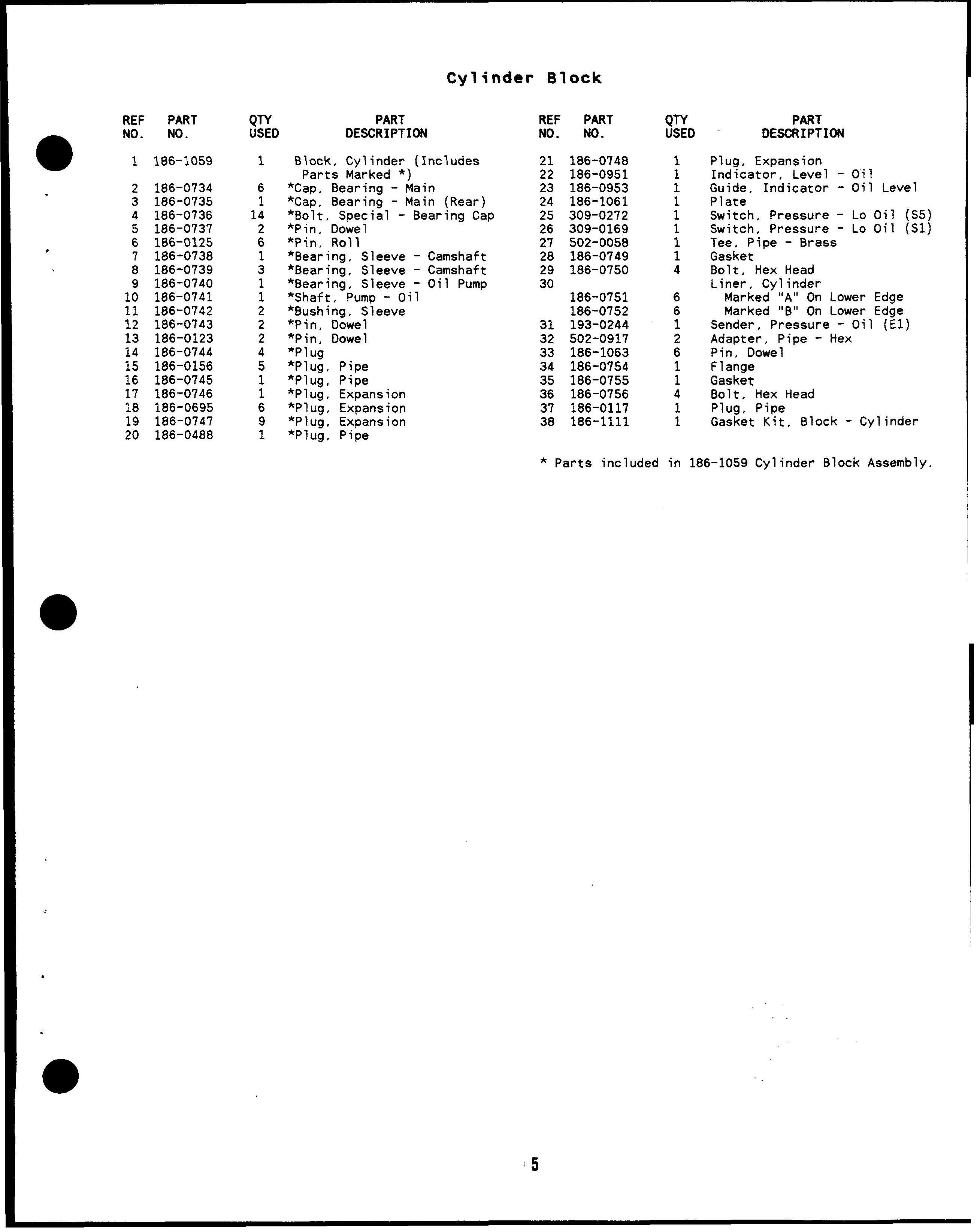
Block, Cylinder 4
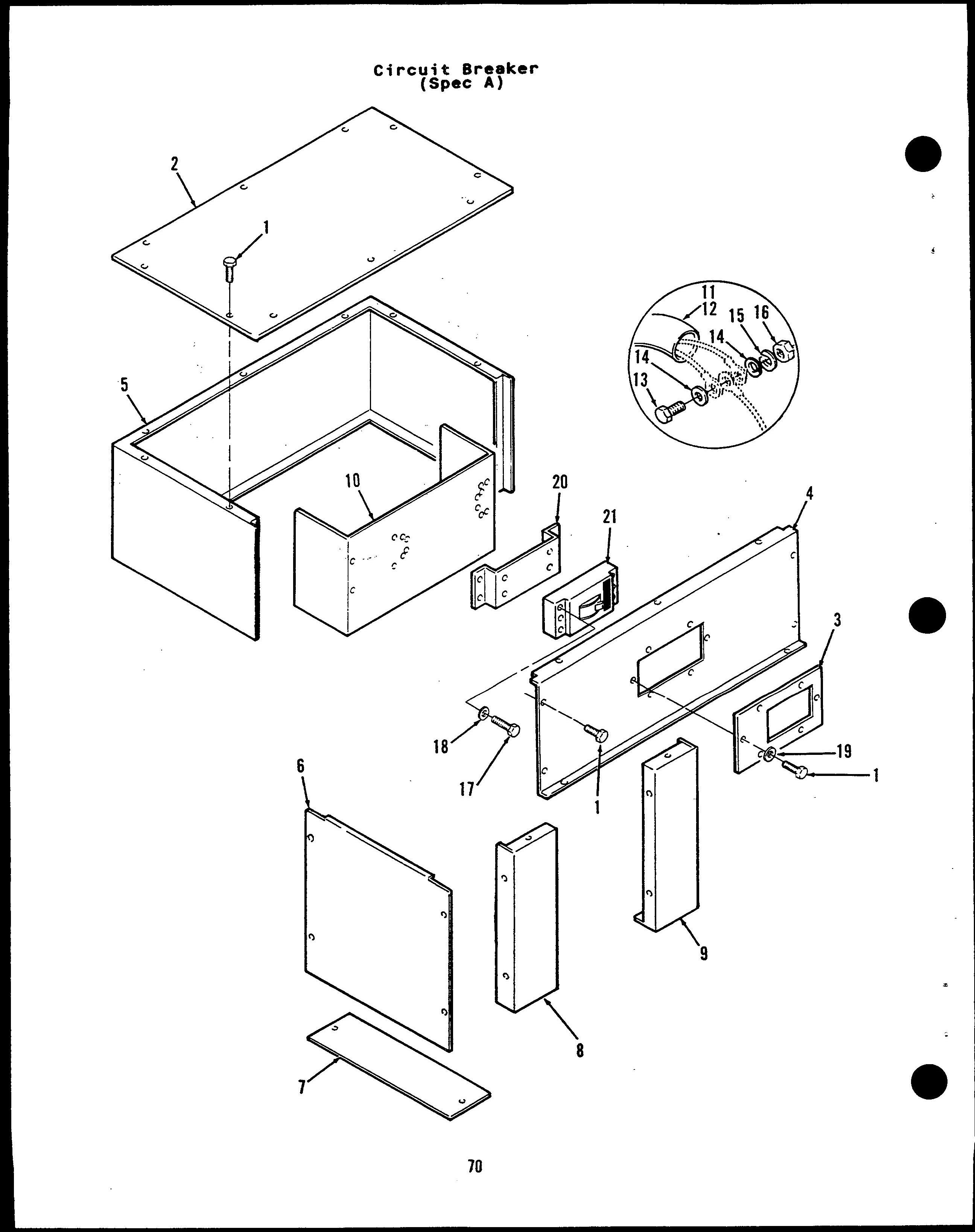
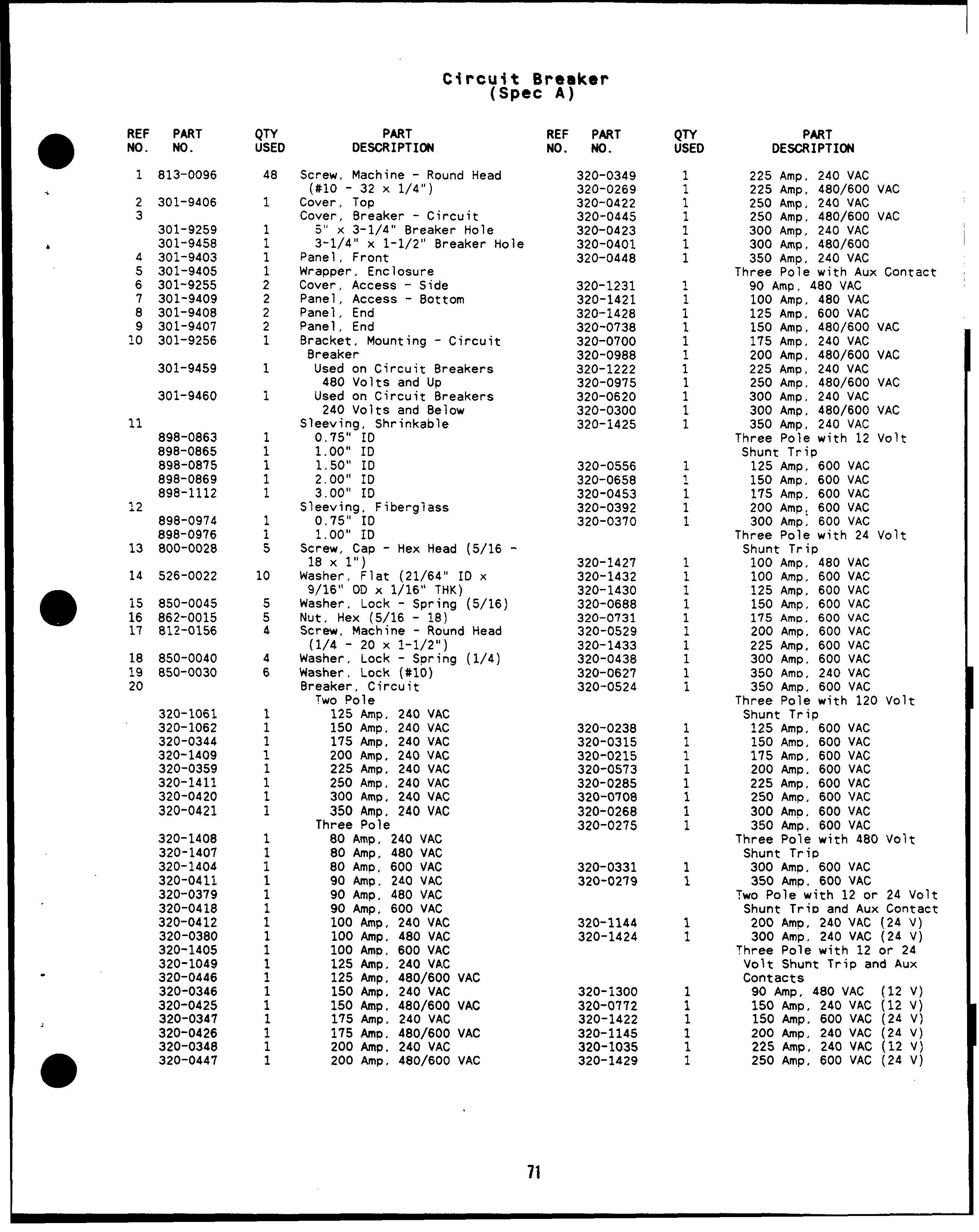
Breaker, Circuit - Spec A 70
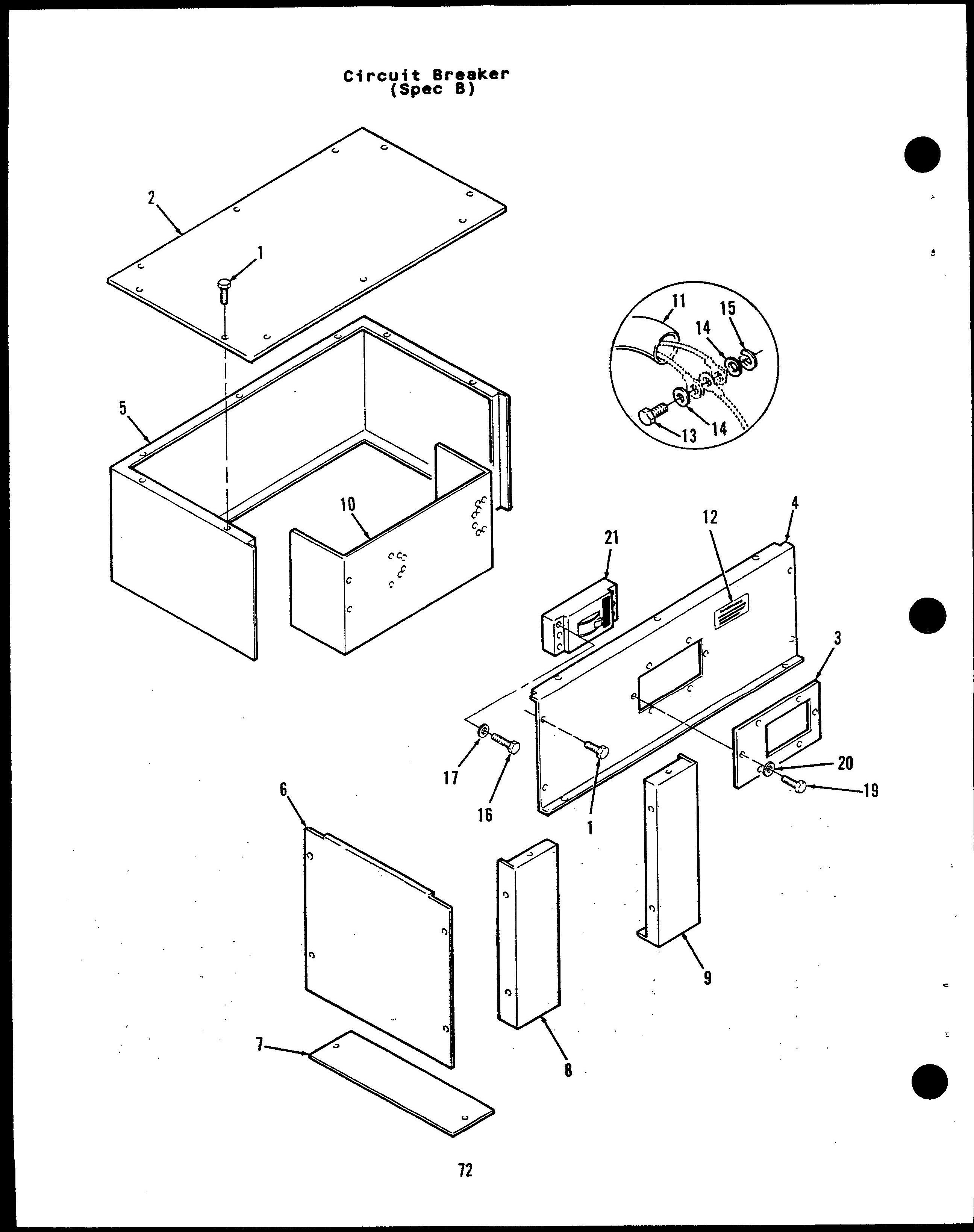
Breaker, Circuit - Spec B 72
Cable, Battery 30
Cable, Pickup - Magnetic 38
Camshaft 6
Cap, Radiator 40, 42
Chassis 50
Cleaner, Air 44. 45
Clutch, Starter 32
Coil, Field - Starter 32
Control, Engine 62
Control, Generator 64
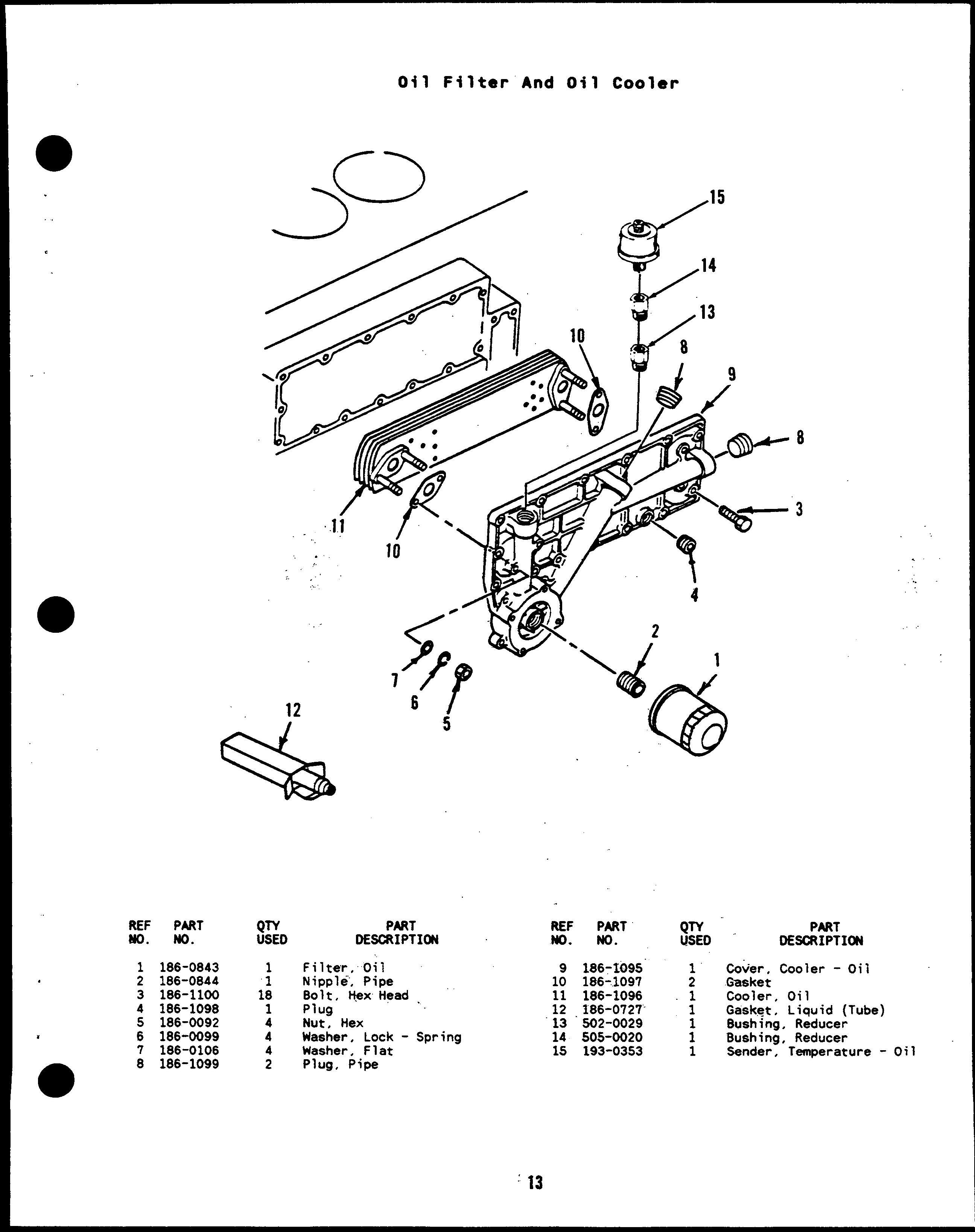
Cooler, Oil 13
Cooling System 40, 42
Cover, Gear 10
Cover , Head - Cylinder 19
Crankshaft 6
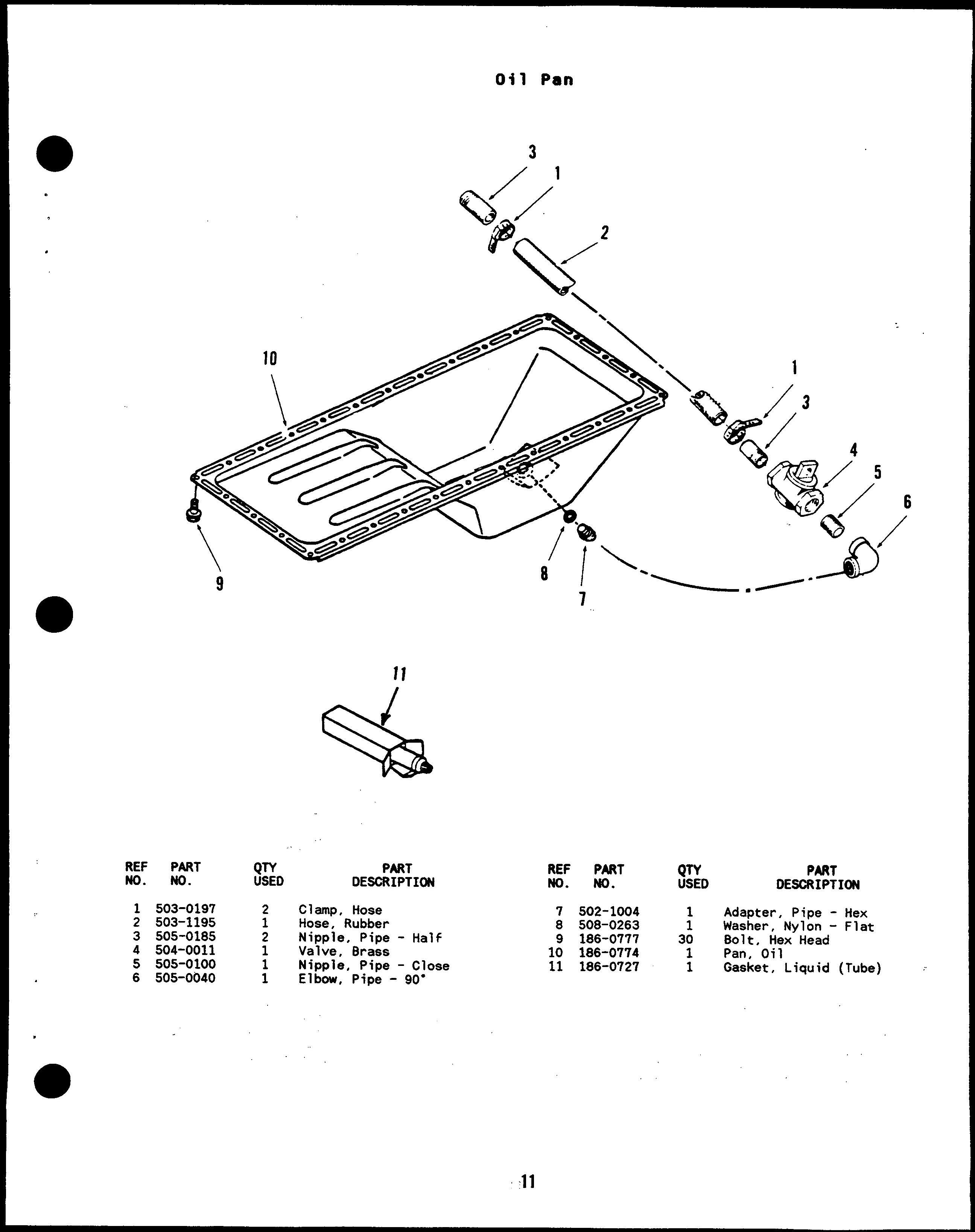
Drain, Oil 11
Exhaust System 22
Fan, Cooling 39
Filter, Air 44, 45
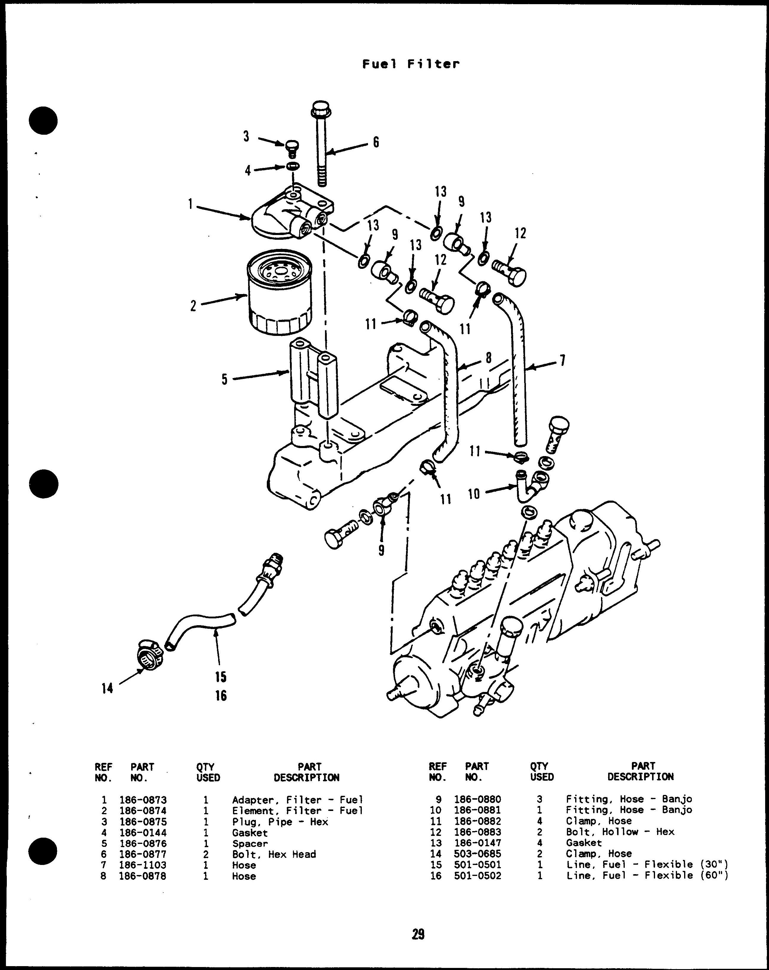
Filter, Fuel 29
Filter, Oil 13
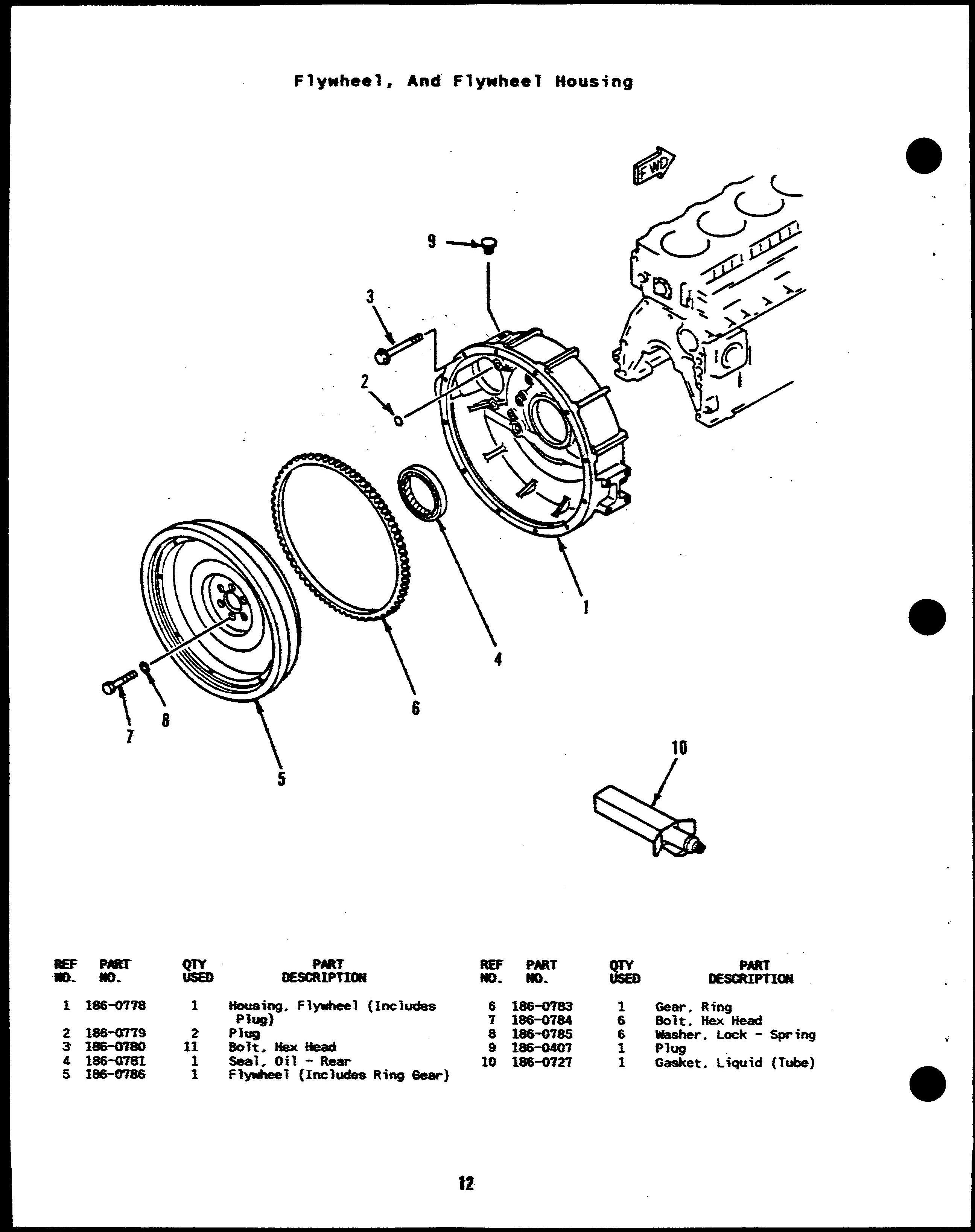
Flywheel 12
Gauge, Pressure - Oil 62
Gauge, Temperature - Oil 62
Gauge, Temperature - Water 62
Gear, Ring 12
Gearcase 10
Generator 54, 56
Governor, Electronic 38
Guard, Belt 40, 42
Guard, Fan 40, 42
Guide, Valve 14
Harness, Wiring - Control (AC) 64
Harness, Wiring - Control (DC) 62
Harness, Wiring - Control To Engine 30
Harness, Wiring - Lo Coolant Level 40. 42
Harness, Wiring - Watts Transducer 67
Head, Cylinder 14
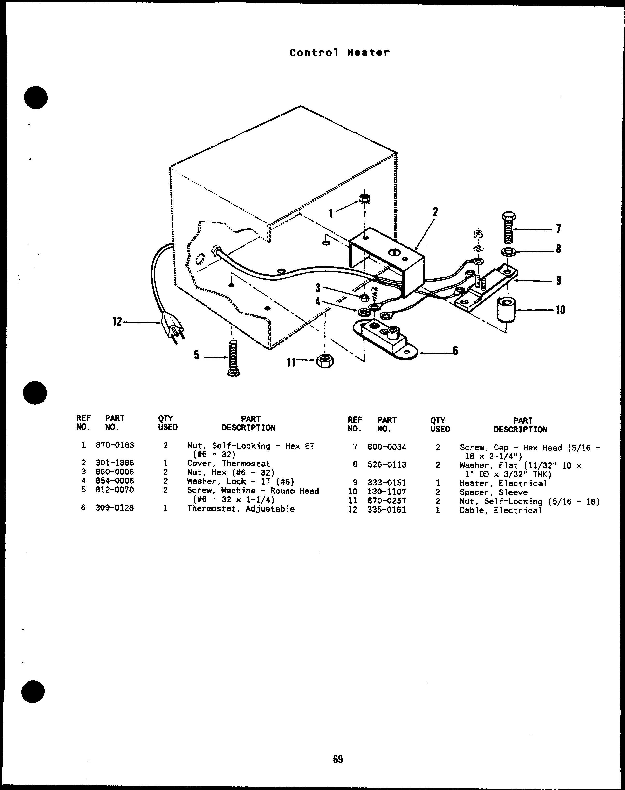
Heater, Control 69
Heater, Coolant - Engine 48
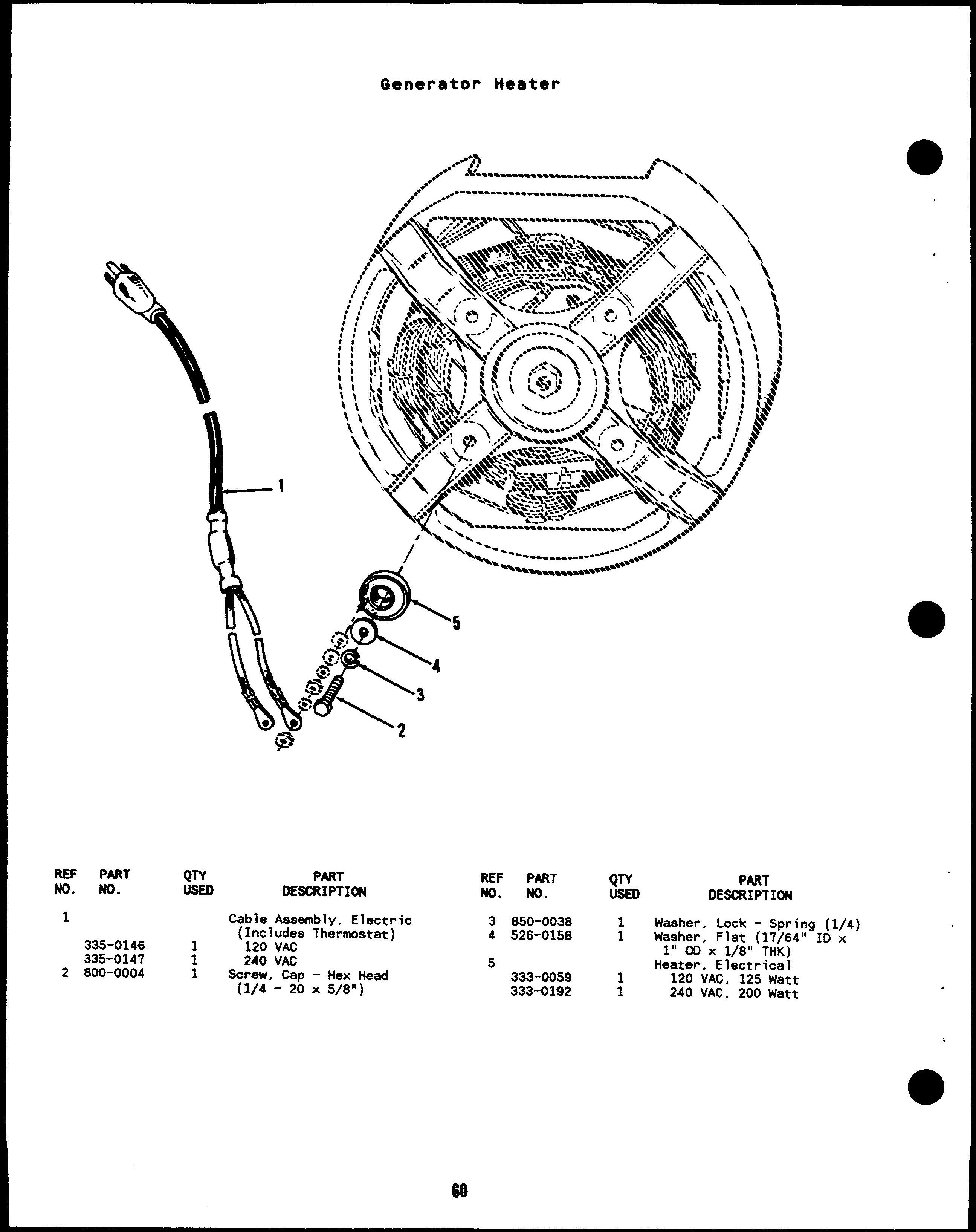
Heater, Generator 60
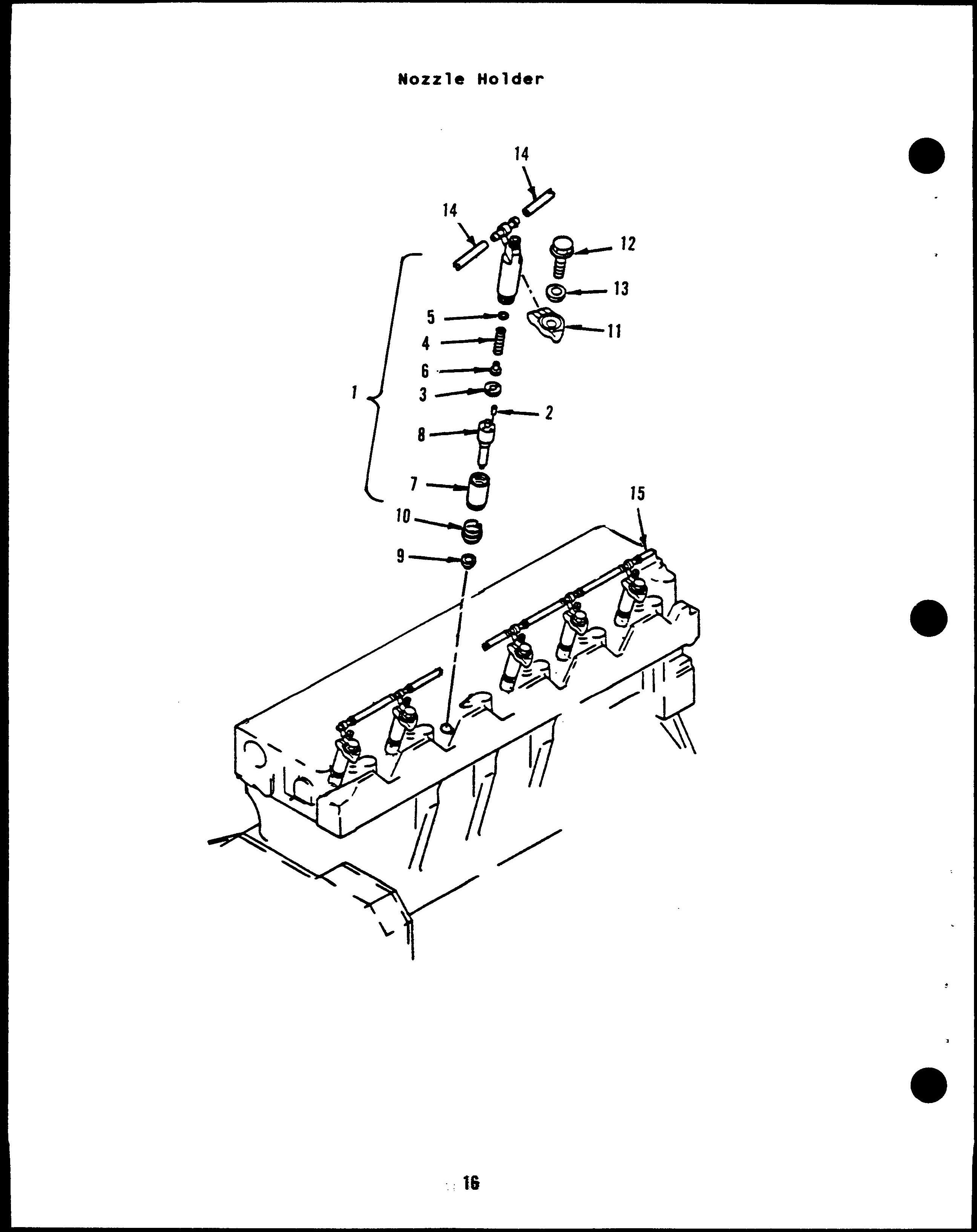
Holder, Nozzle 16
Hose, Drain - Oil 11
. Hose, Radiator 40. 42
Housing, Control 68
Housing, Flywheel 12
Housing, Set 52
Impeller, Pump - Water 39
Indicator, Level - Oil 4
Indicator, Service - Air Cleaner 44. 45
Kit, Gasket - Block - Cylinder 4
Kit, Gasket - Head - Cylinder 14
Light, Indicator 62, 64
Line, Fuel 29
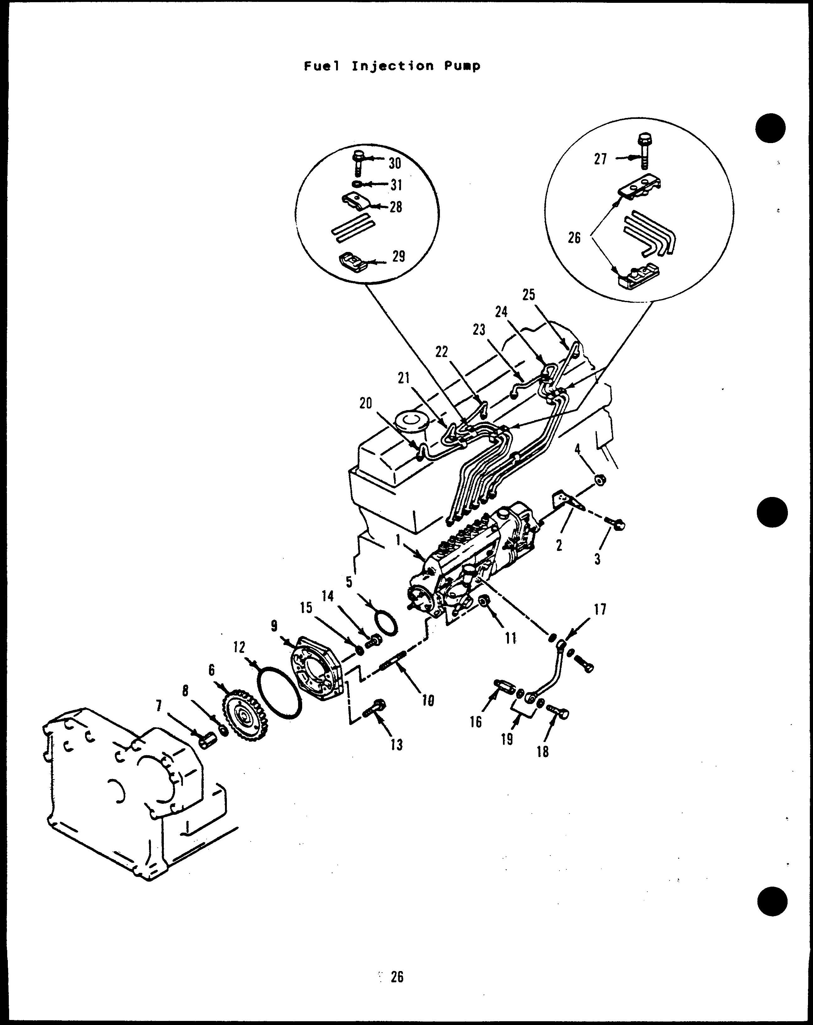
Line, Injection - Fuel 26
Liner, Cylinder 4
Manifold, Exhaust 20
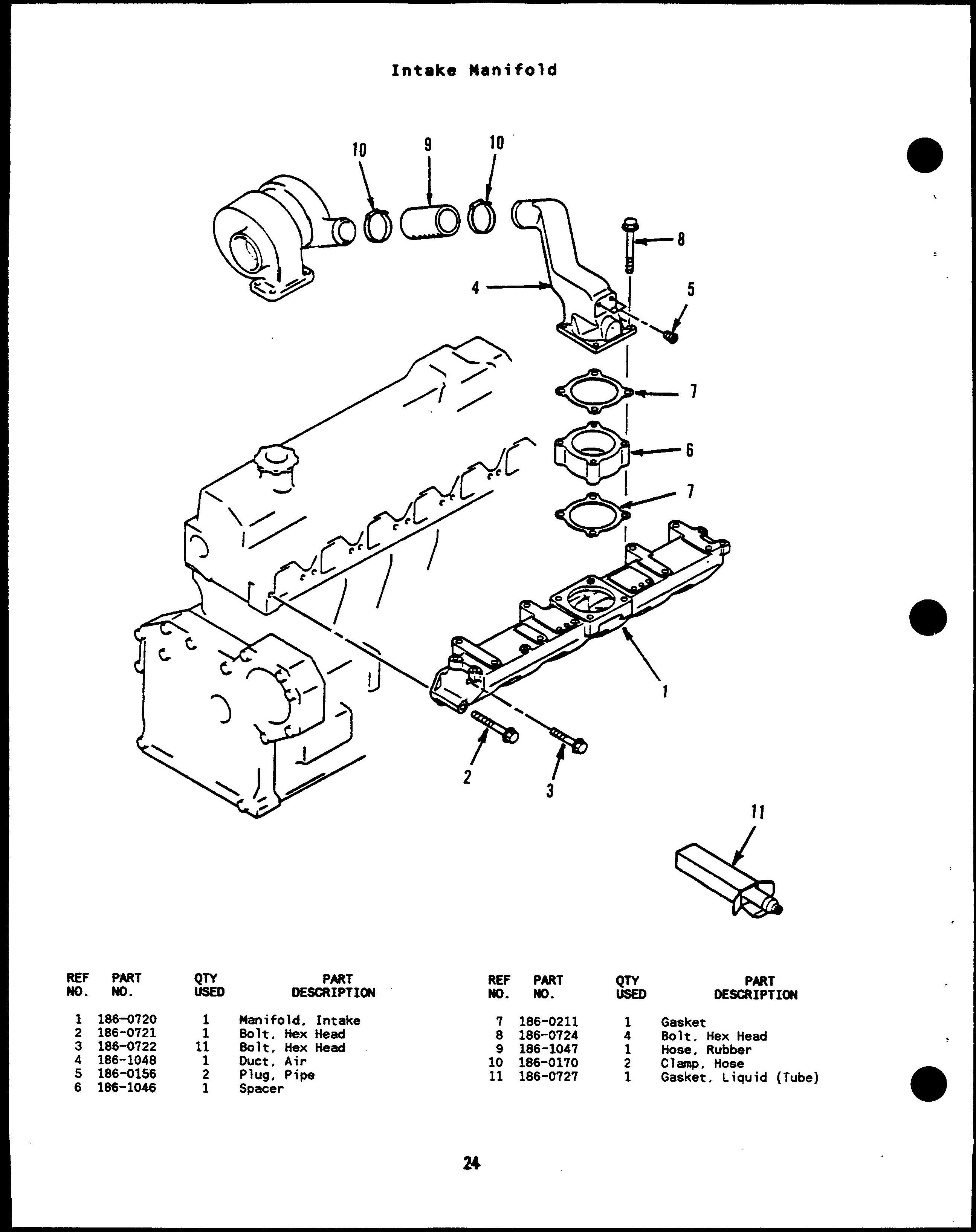
Manifold, Intake 24
Meter, Ampere 62, 64
Meter, Frequency 64
Meter, Tach 62
Meter, Time - Running 62
Meter, Volt 64
Meter, Watt 67
Muffler, Exhaust 22
Nozzle, Fuel 16
Pan, Oil 11
Pickup, Magnetic 61 Piston 8
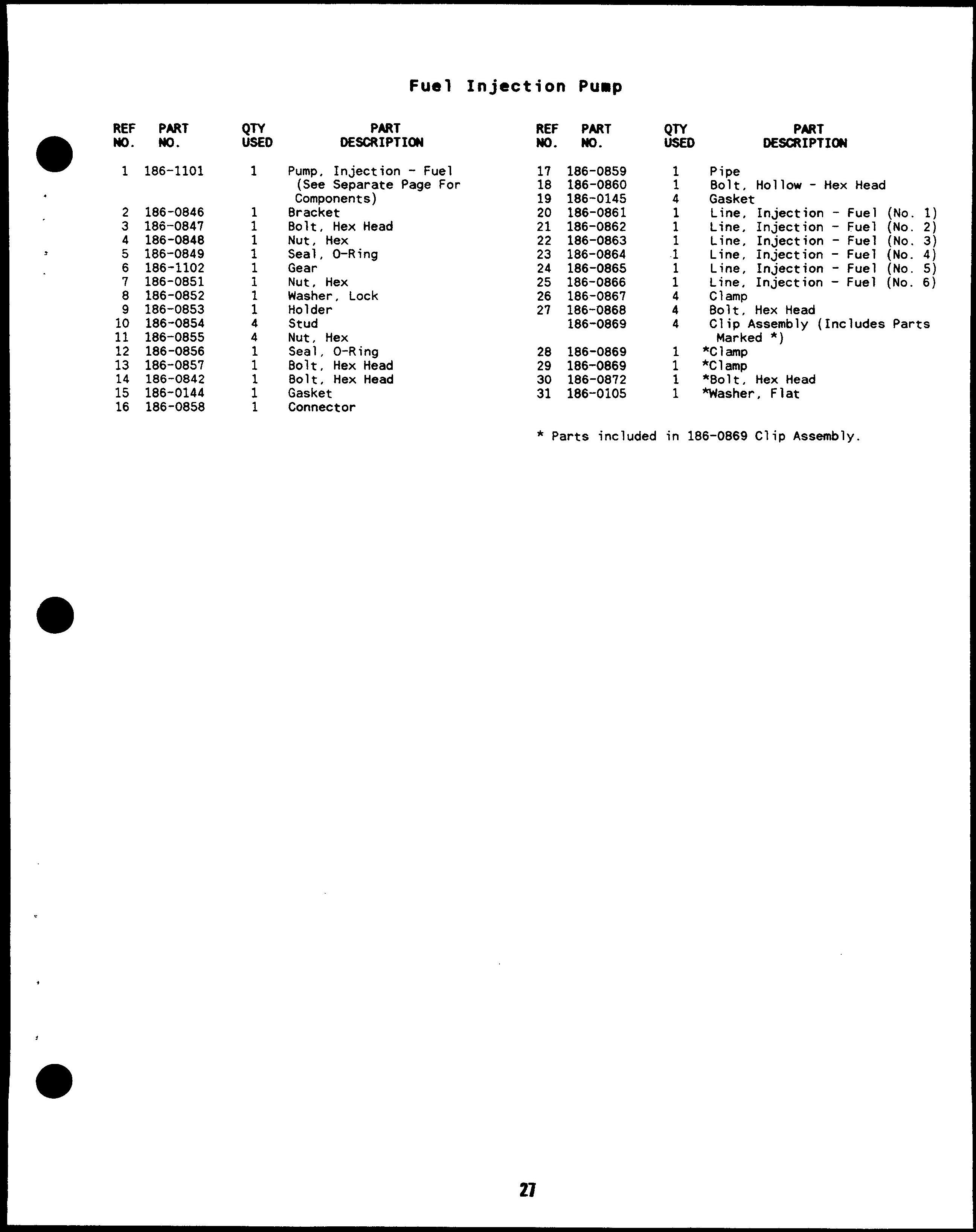
Pump, Injection - Fuel 26
Pump, Injection - Fuel (Components)
Pump, Oil 6
Pump, Water 39
Radiator 40. 42
Radiator, Remote 46
Regulator, Voltage 35, 36, 64
Rod , Connecting 8
Rod, Push 8
Rotor, Alternator 35, 36
Rotor, Exciter 54, 56
Rotor, Exciter - Components 58
Rotor, Generator 54, 56
Seal , Oil - Front 10
Seal, Oil - Rear 12
Seat, Valve 14
Sender, Level - Lo Coolant 40, 42
Sender, Pressure - Oil 4
Sender, Temperature - Oil 13
Sender, Temperature - Water 39
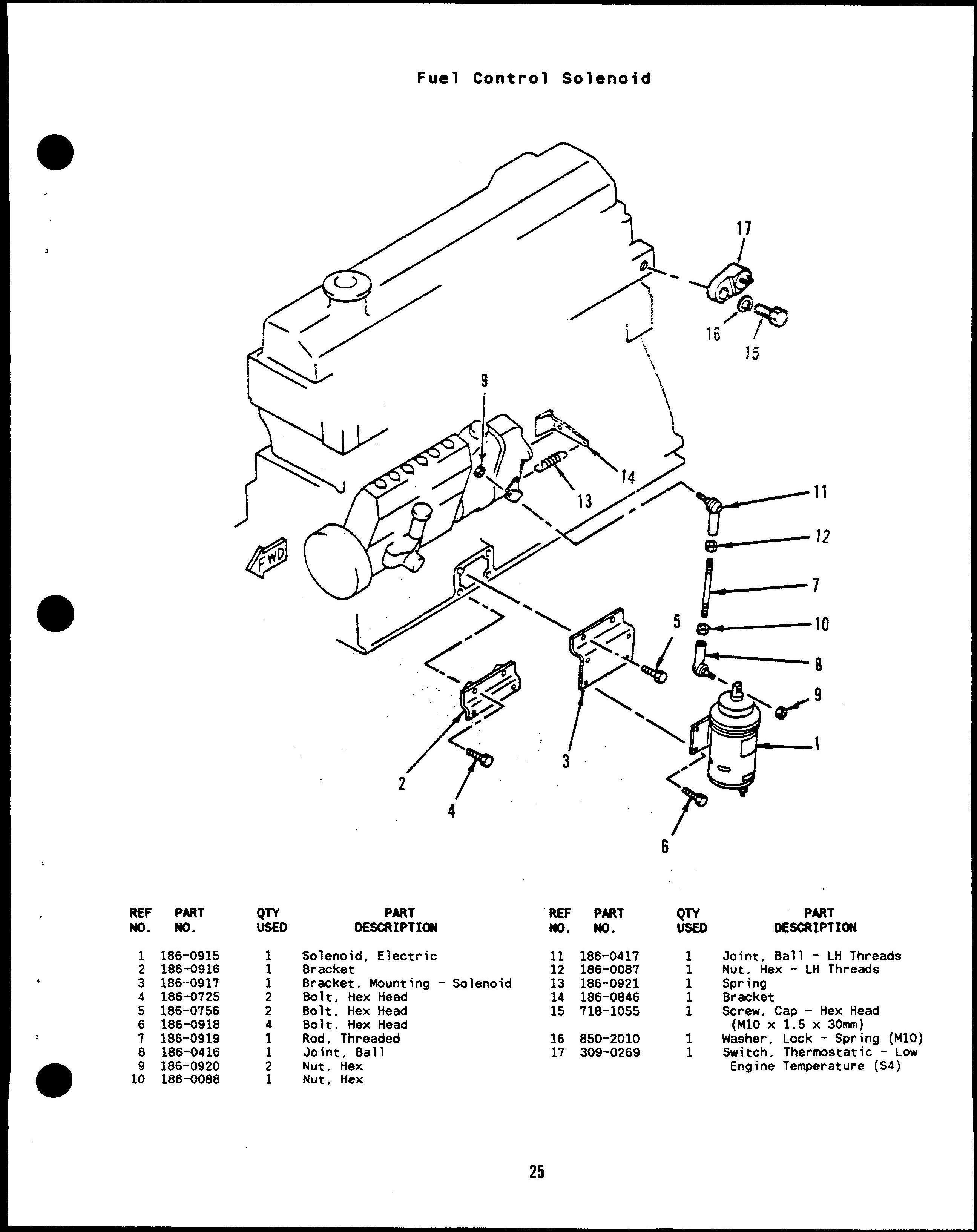
Solenoid, Control - Fuel 25
Solenoid, Starter 32
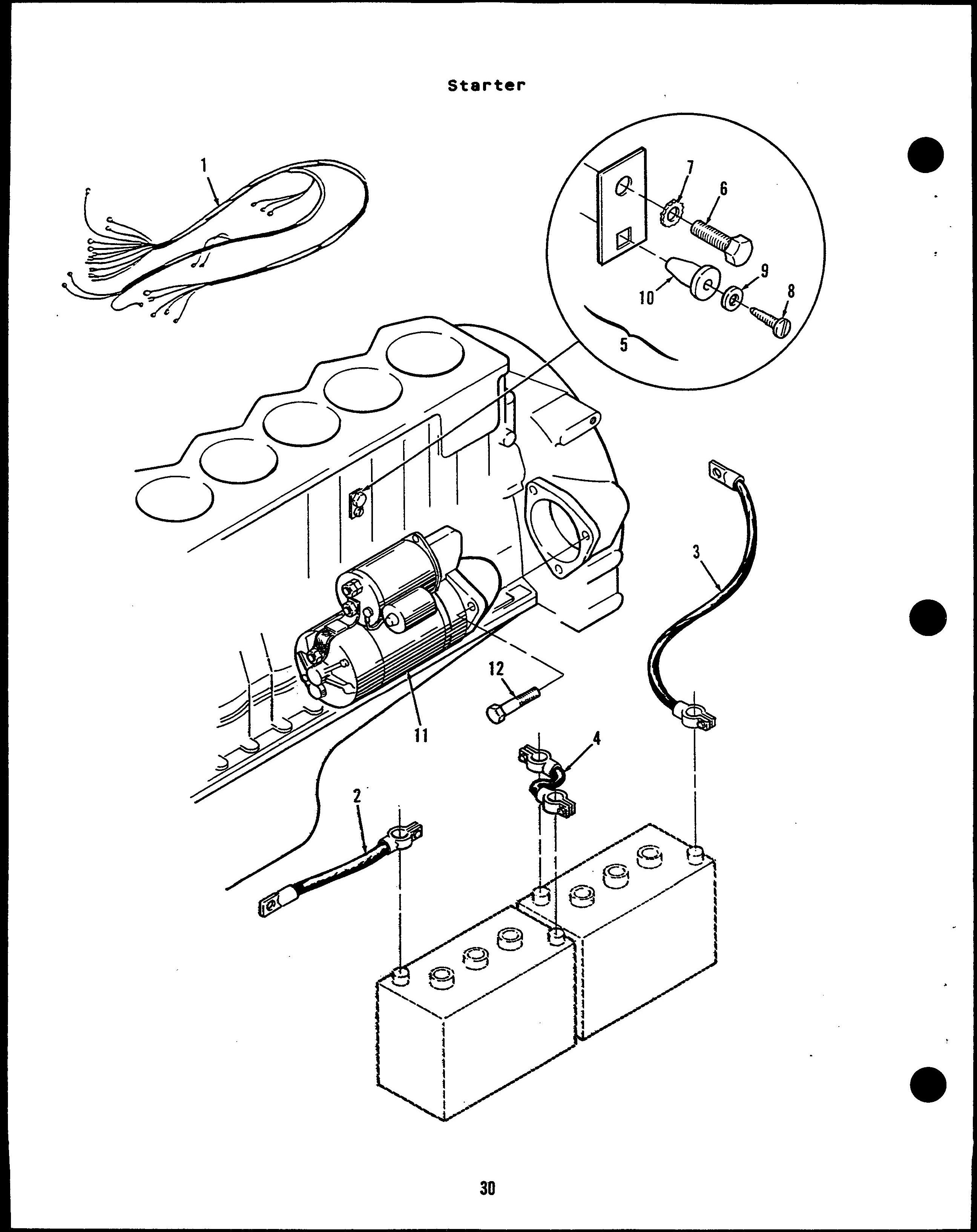
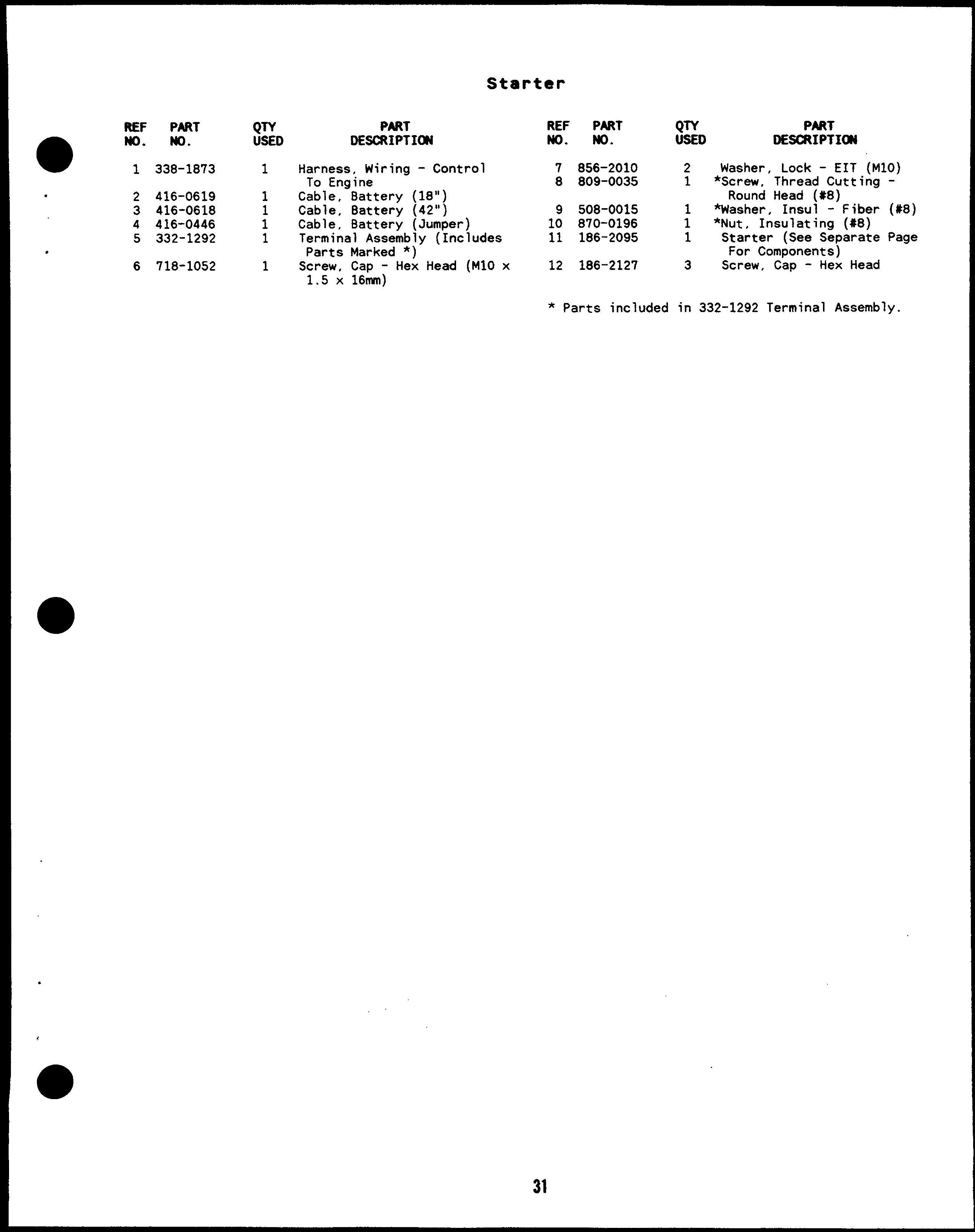
Starter 30
Starter Components 32
Stator, Alternator 35, 36
Stator, Exciter 54, 56
Stator, Generator 54, 56
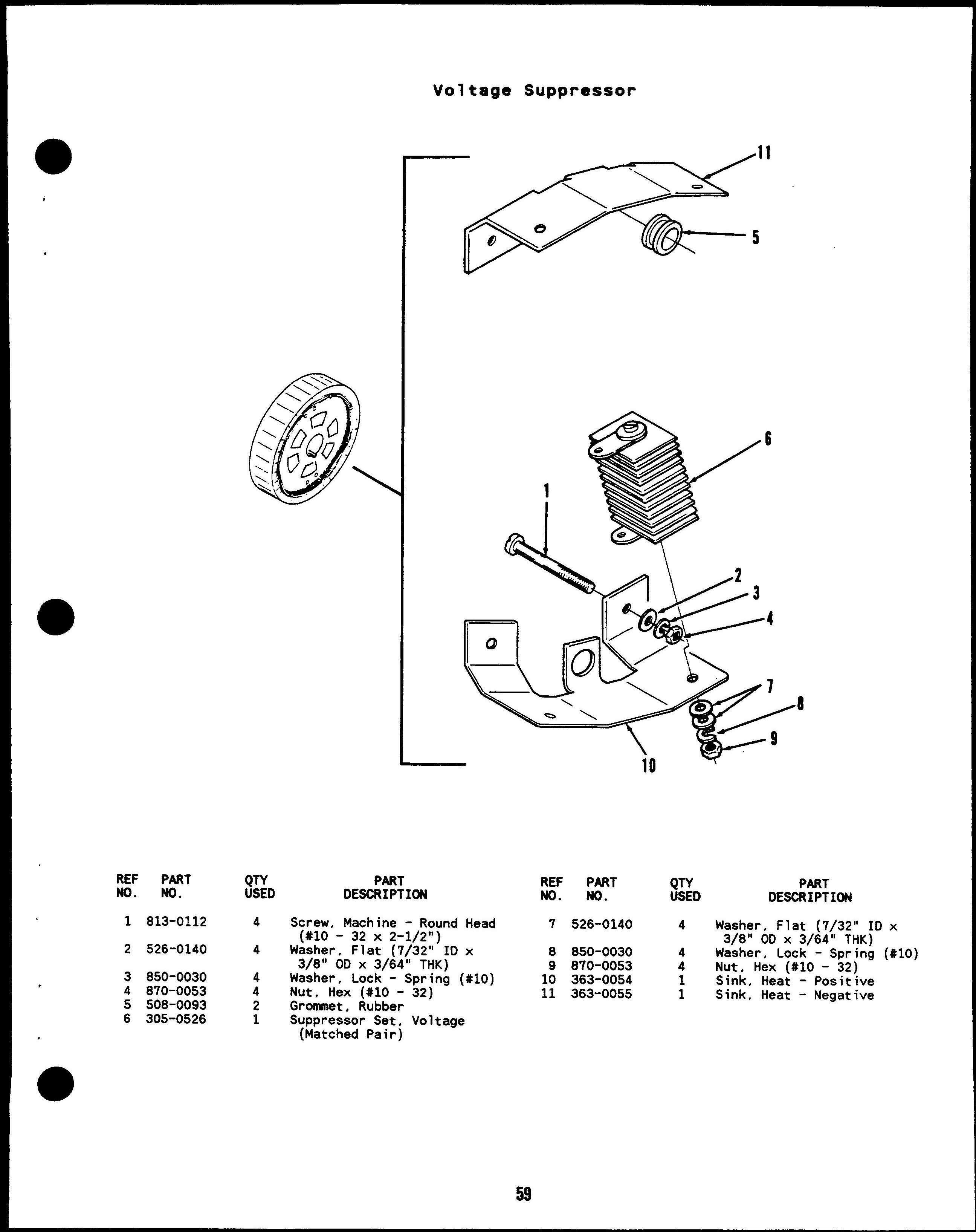
Suppressor, Voltage 59
Switch, Level - Lo Coolant 40, 42
Switch, Overspeed 61
Switch, Pressure - Oil 4
Switch, Push - Reset/Panel 62
Switch, Push - Run/Stop/Remote 62
Switch, Rotary - Generator Control
Switch, Safety - Oil 4
Switch, Shutdown - PreOil
Switch, Temperature - Hi Eng
Switch, Temperature - Lo Eng
Tappet 8
Thermostat, Temp - Hi Water
Thermostat, Temp - Pre Water
Transformer, Current 66
Turbocharger 20
Valve, Drain - Oil 11
Valve, Exhaust 14
Valve, Intake 14
67
This Parts Manual applies to the Standard Sets Listed below. The illustrations are arranged in groups of related items, and each part or aasembly is identified by a Reference Number. All parts illustrated are typical, and unless otherwise mentioned in the description column the parts are interchangeable between models.
These typical illustrations are subject to change and reflect only the latest replacement parts arrangement. The Right and Left sides of the Set are determined by FACING the FRONT (Engine end) of the Set.
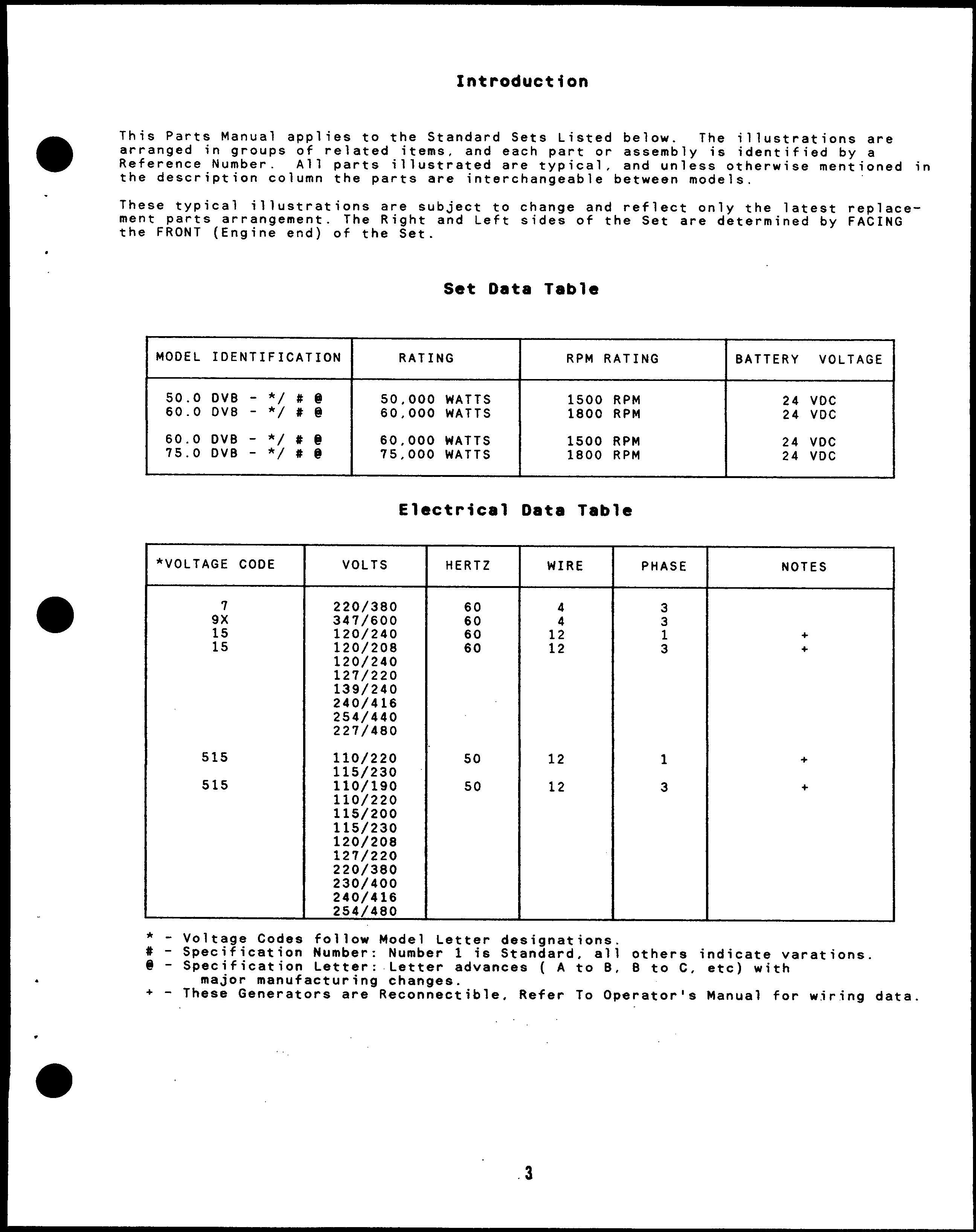
* - Voltage Codes follow Model Letter designations.
# - Specification Number: Number 1 is Standard, all others indicate varations.
@ - Specification Letter: Letter advances ( A to B, 8 to C, etc) with major manufacturing changes.
+- These Generators are Reconnectable, Refer To Operator’s Manual for wiring data.
Switch,
Gasket
Bolt,
Liner,
Sender,
Adapter, Pipe
Gasket
8olt, Hex Head
Plug,
Gasket Kit, Block - Cylinder
Hex Head
Pickup - Oil
O-Ring 8olt, Hex Head
Hex Head Crankshaft (Includes Gear and Key)
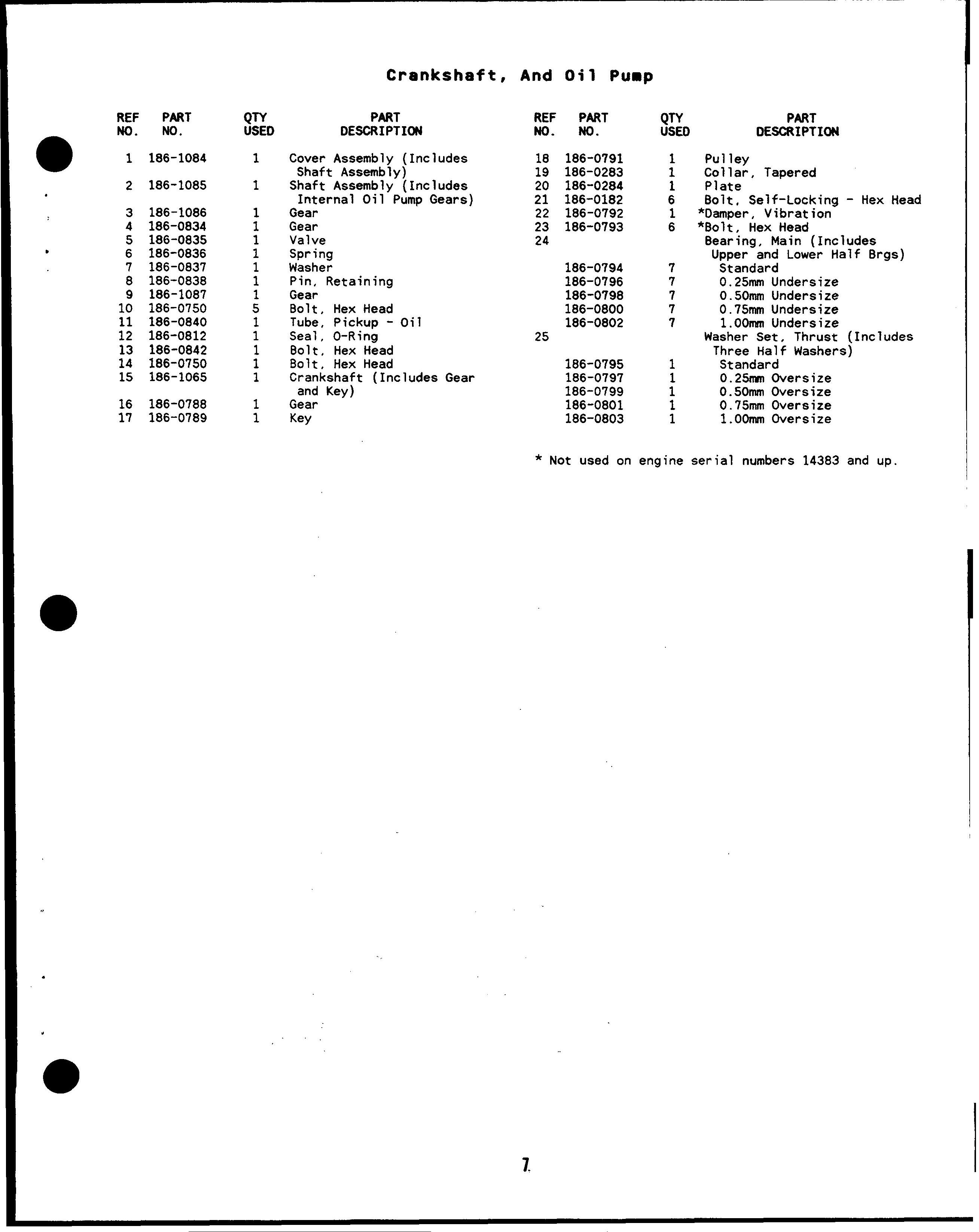
*Damper, Vibration
*801t, Hex Head 8earing, Main (Includes Upper and Lower Half 8rgs)
Undersize
Undersize
1.00mm Undersize Washer Set, Thrust (Includes Three Half Washers)
Oversize
Oversize
Oversize
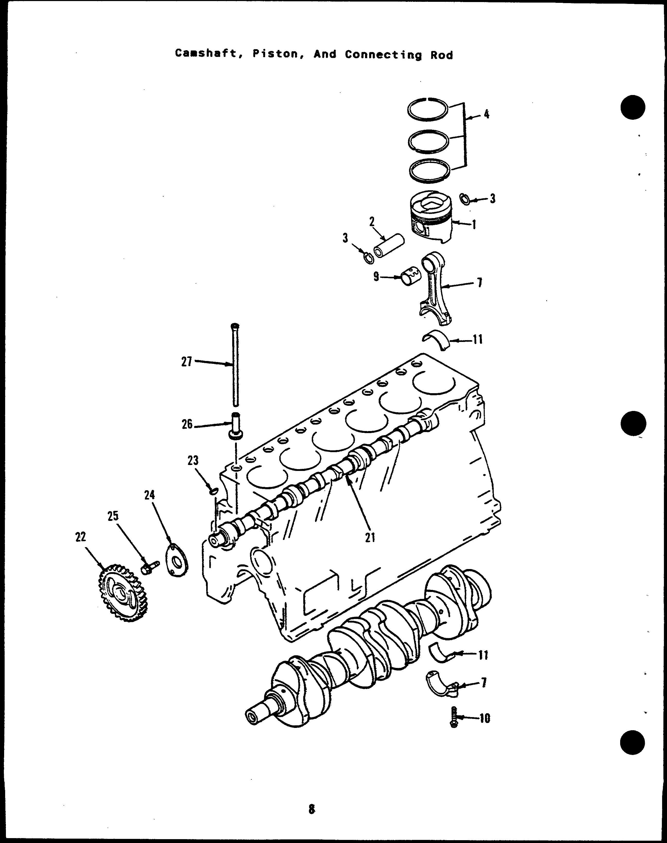
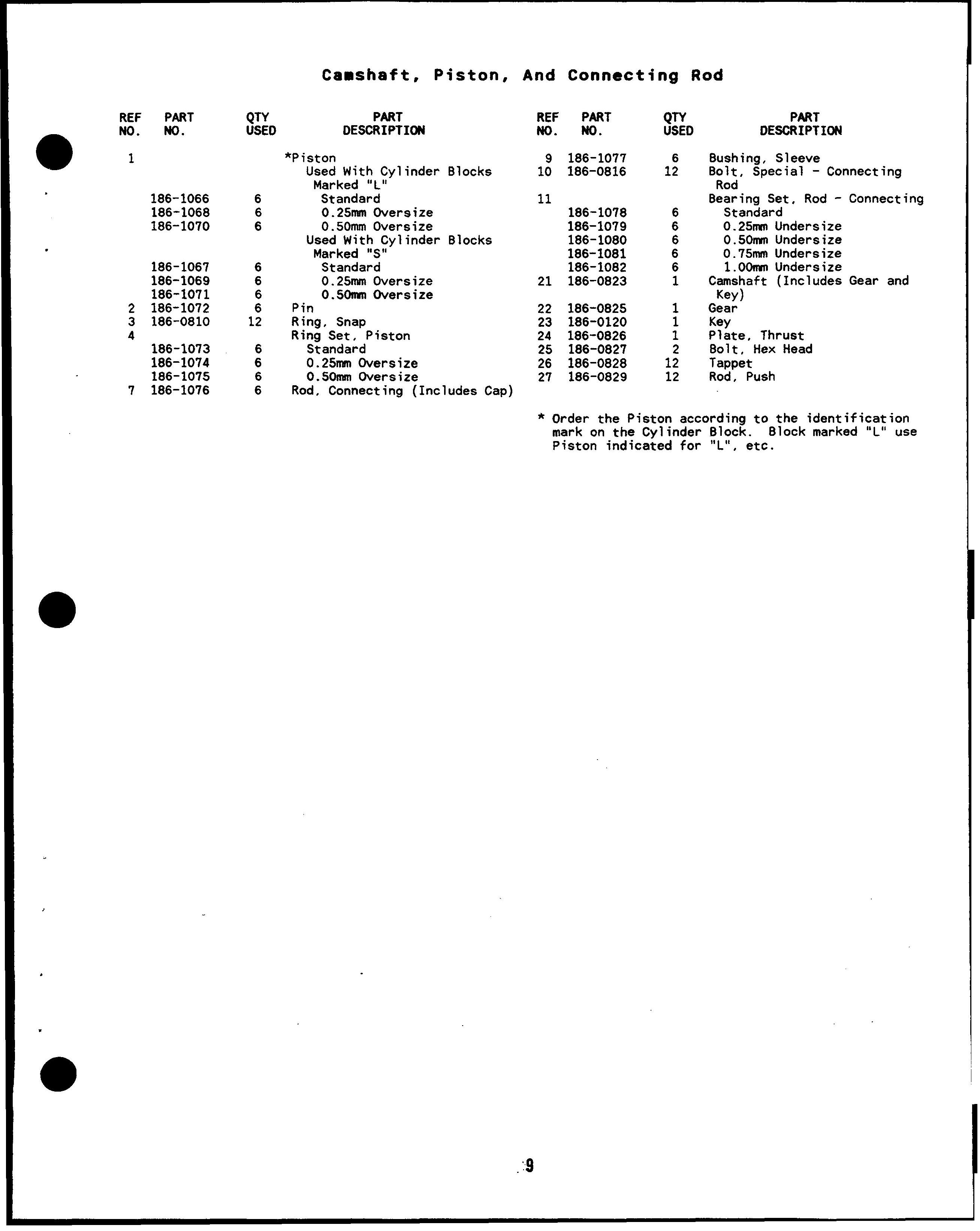
Oversize 0.50mm Oversize Used With Cylinder Marked “S”
Oversize O.SOnsn Oversize Pin Ring, Snap Ring Set, Piston
Rod, Connecting (Includes
Bushing, Sleeve Bolt, Special - Connecting Rod
Bearing Set, Rod - Connecting Standard 0.25MM Undersize
0.50nsn Undersize
0.75MM Undersize
1.00rmn Undersize
Camshaft (Includes Gear and Key)
Gear
Key Plate, Thrust Bolt, Hex Head Tappet Rod, Push
Order the Piston according to the identification mark on the Cylinder Block. 810ck marked “L”
Piston indicated for “L”, etc
Engine Parts contact: Phone 269 673 1638 Email: engineparts2@gmail.com www.Diesel-Generator-Engine-Parts.com
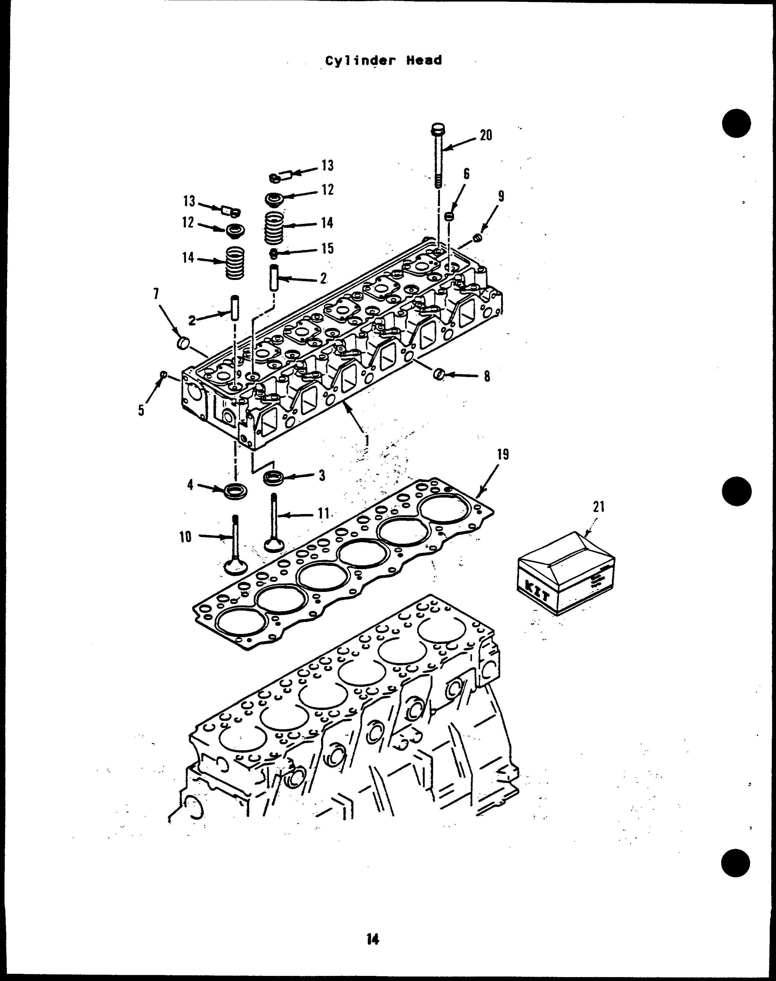
1 Head Assembly, Cylinder 7 186-0694 5 +*Plug, Expansion 186-0686 1 With Valves (Includes 8 186-0695 16 +*Plug, Expansion Parts Marked*) 9 186-0696 1 +*Plug, Expansion 186-0687 1 Less Valves (Includes 10 186-0698 1 *Valve, Intake Parts Marked+) 11 186-0699 1 *Valve, Exhaust
2 186-0688 12 +*Guide, Valve 12 186-0700 12 *Seat, Sprrng 3 Seat, Valve - Exhaust 13 186-0701 24 *Collet, Lock - Valve 186-0689 6 +* Standard 14 186-0702 12 *Valve, Spring 186-0690 6 0.25mm Oversize 15 186-0703 6 *Seal, Stem - Valve 186-0691 6 0.50mm Oversize 19 186-0705 1 Gasket
4 186-0697 1 +*Pipe, Breather 20 186-0706 25 Cylinder Head Bolt
5 186-0692 6 +*Plug, Expansion 21 186-0949 1 Gasket Kit, Head - Cylinder 6 186-0693 7 +*Plug, Expansion * Parts included in 186-0686 Cylinder Head Assembly. + Parts included in 186-0687 Cylinder Head Assembly.
6209-S1-1622 Cylinder Head Bolt Set includes (25) New 186-0706 Cylinder Head Bolts

McGRAW-EDISON ONAN Komatsu Engine Parts Contact: Email: EngineParts@HeavyEquipmentRestorationParts.com Phone: 269 673 1638 Website: www.Diesel-Generator-Engine-Parts.com
Soomm
Ssollml
750mm
3oomm
350nwn
375mm
4oomm
475mm 1. Soomm
*Spacer
*Nut, Lock
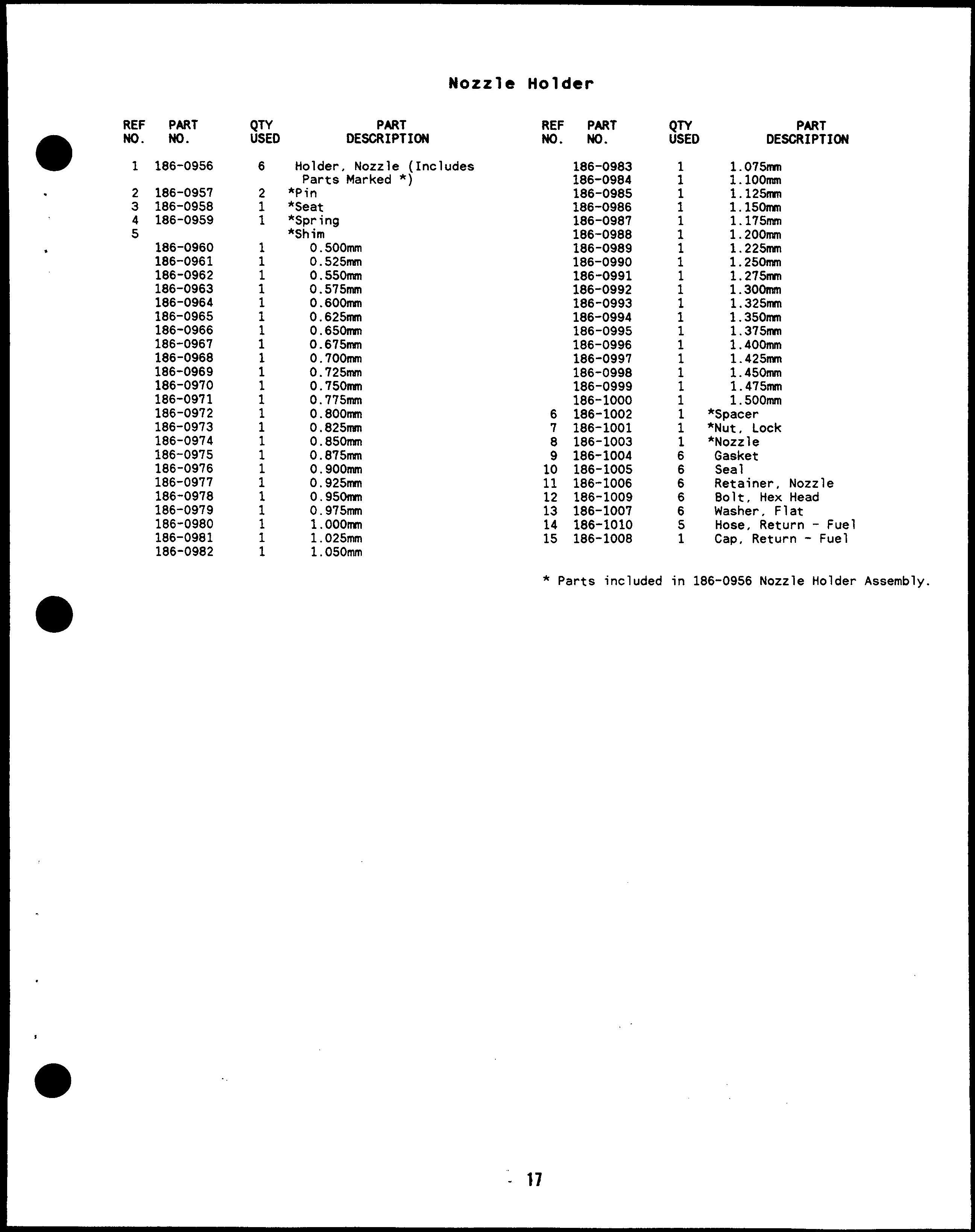
*Nozzle Gasket Sea 1 Retainer, Nozzle 8olt, Hex Head Washer, Flat Hose, Return - Fuel Cap, Return - Fuel * Parts included in 186-0956 Nozzle Holder Assembly.
Clanp, Hose Hose, Rubber
Hose, Rubber
8olt, Hex Head
Line, 8reather
Tube Nut, Hex
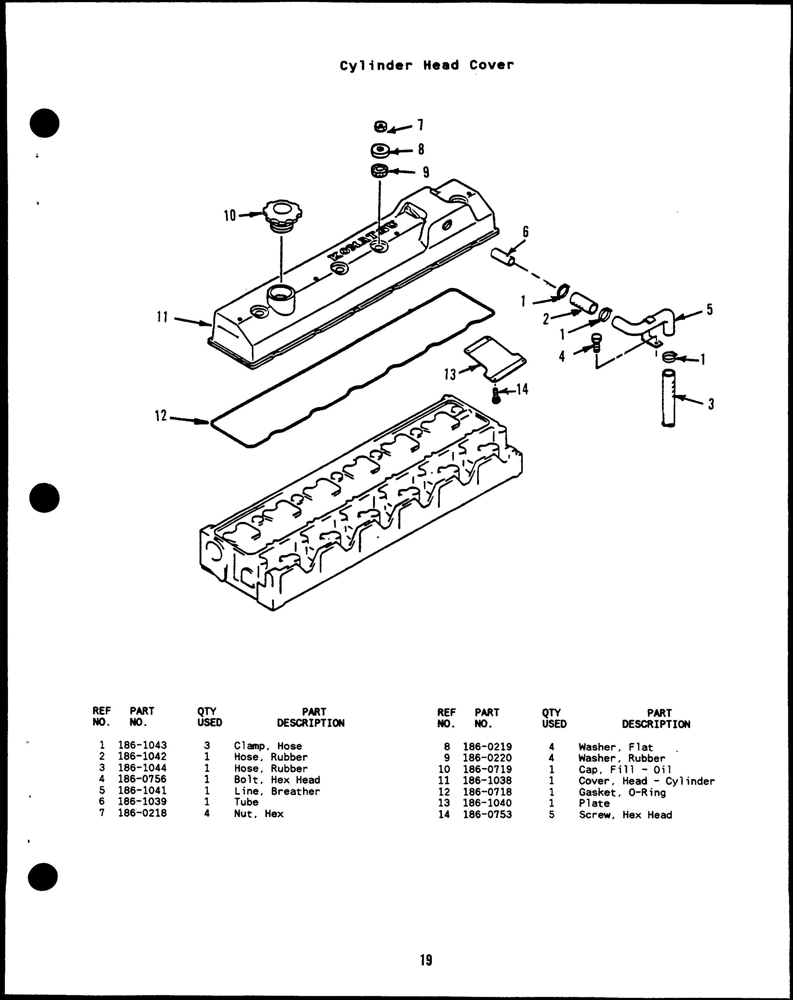
Washer, Flat
Washer, Rubber “ Cap, Fill -Oil
Cover, Head - Cylinder
Gasket, O-Ring
Plate
Screw, Hex Head
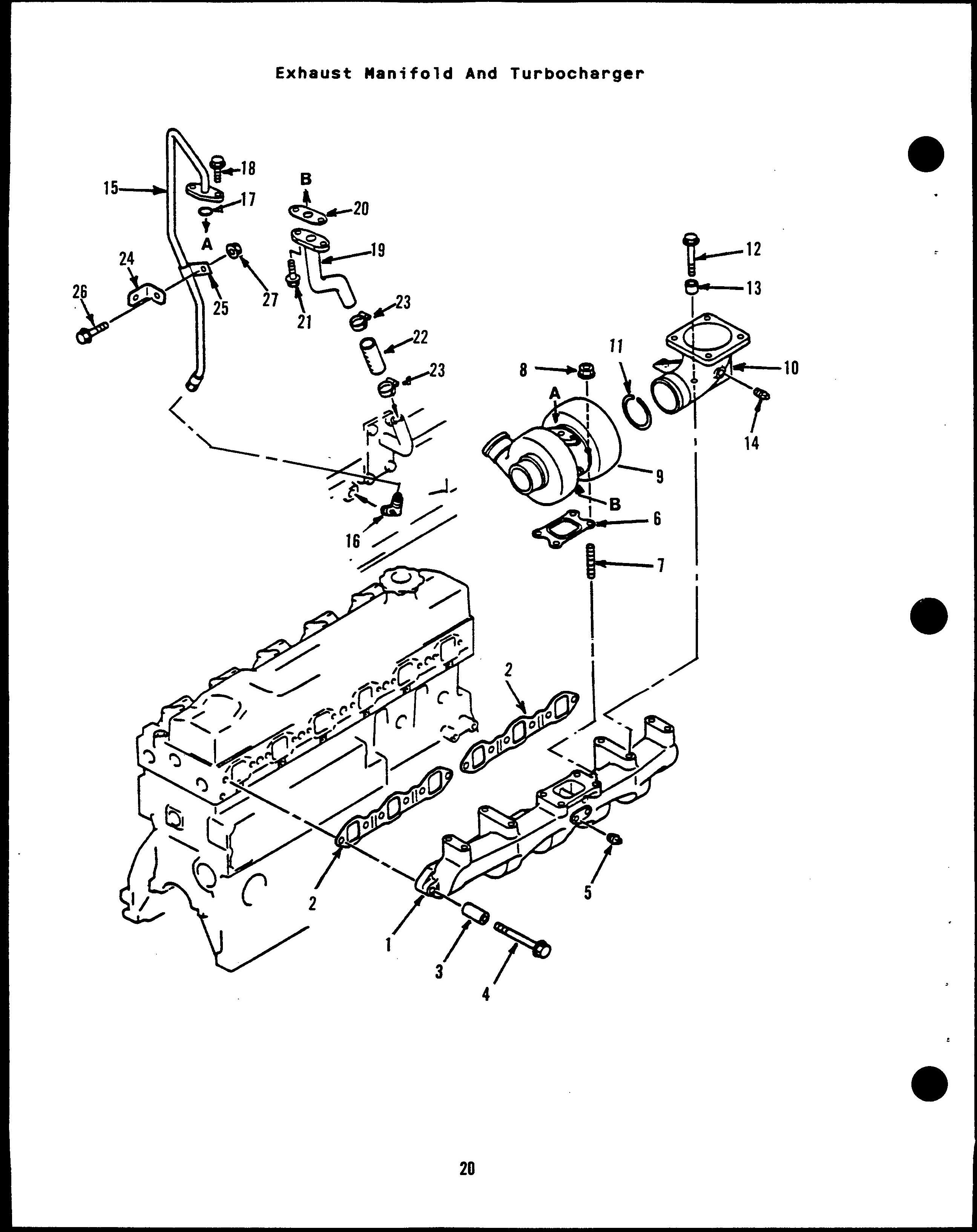
Manifold, Exhaust Gasket Spacer
8olt, Hex Head Plug, Pipe Gasket Stud Nut, Hex Turbocharger Elbow, Exhaust Ring, Sealing 8olt, Hex Head (M1O x 1.5 x40mm) Spacer
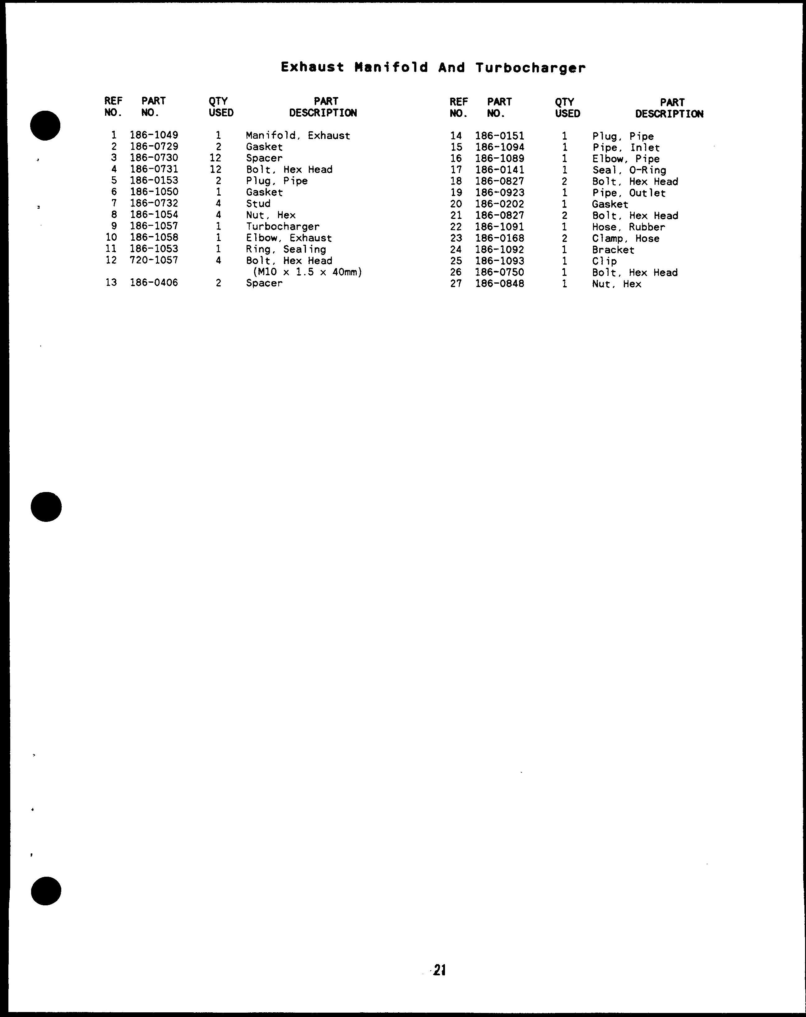
Plug, Pipe Pipe, Inlet Elbow, Pipe Seal, O-Ring Bolt, Hex Head Pipe, Outlet Gasket 8olt, Hex Head Hose, Rubber Clamp, Hose Bracket Clip Bolt, Hex Head Nut, Hex
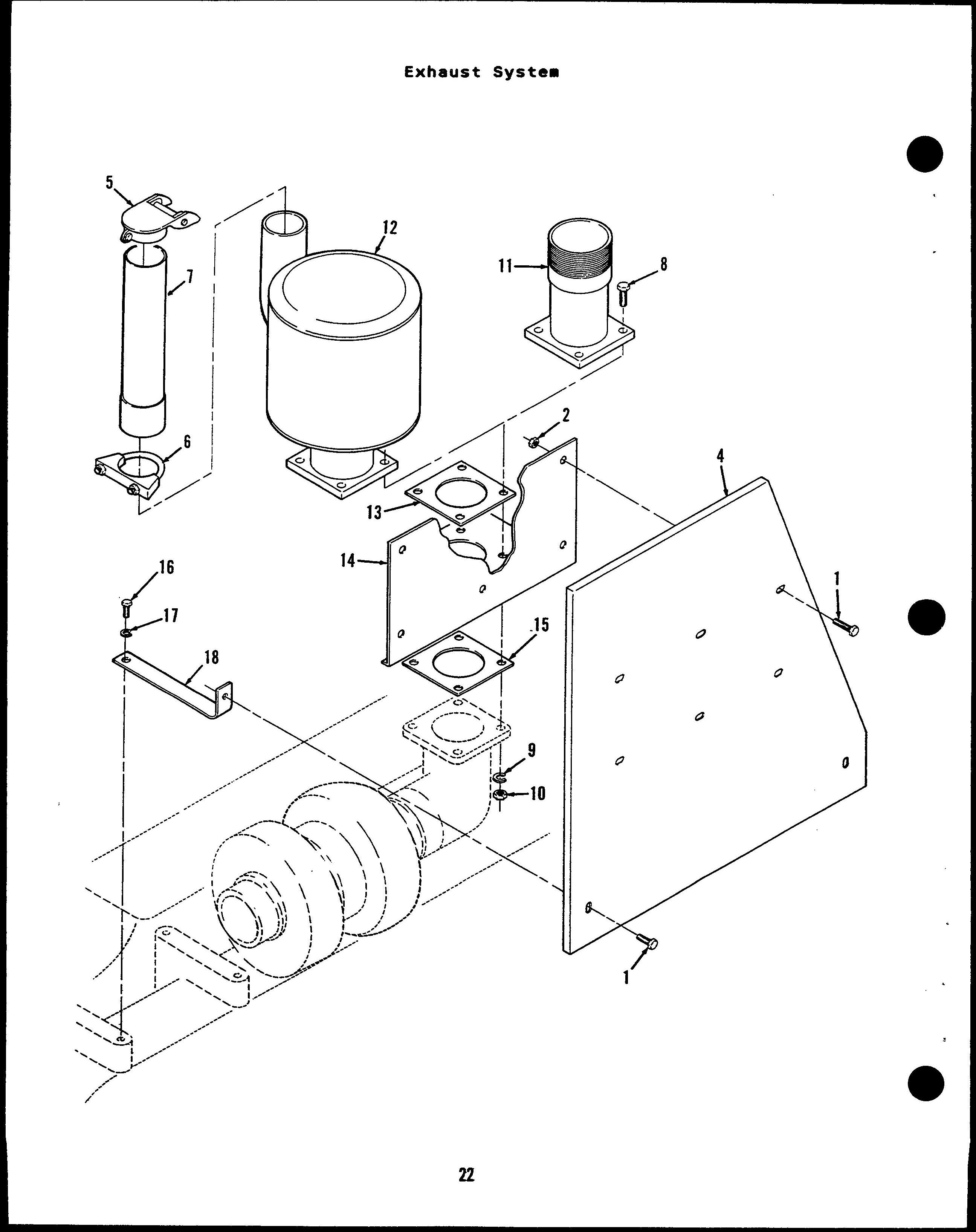
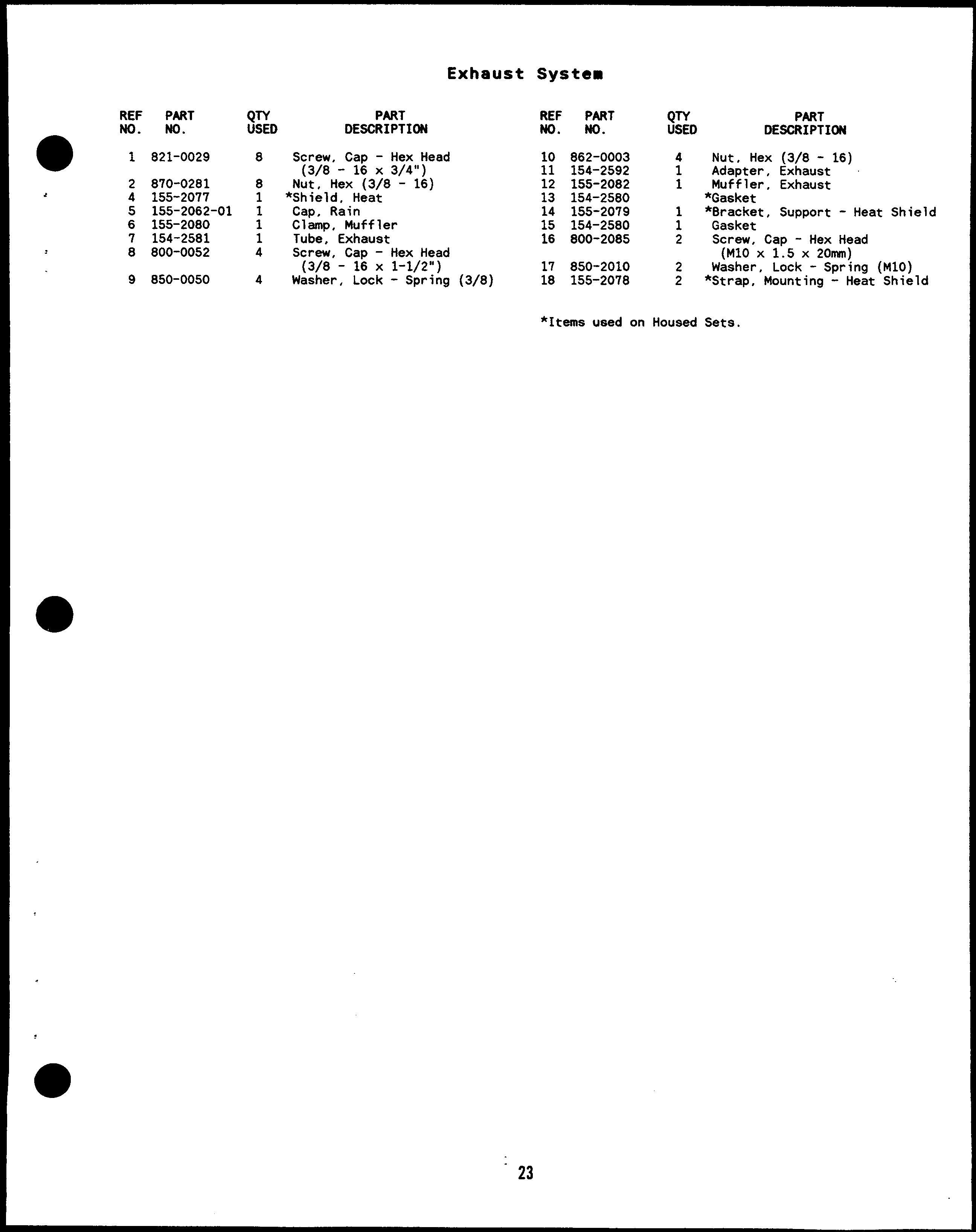
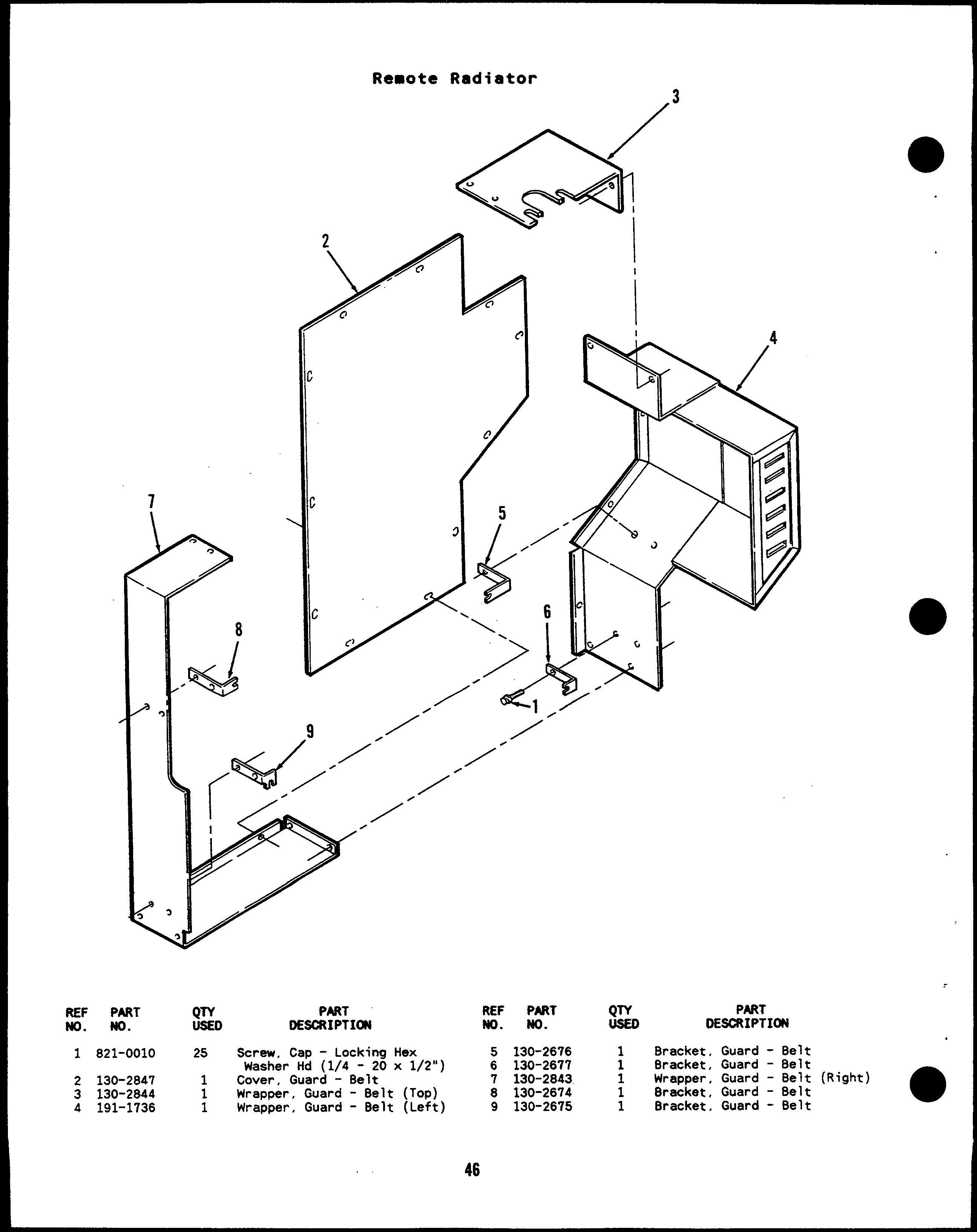
Screw, Cap - Hex Head (3/8 - 16 X 3/4”)
Nut, Hex (3/8 - 16)
*Shield, Heat Cap, Rain Clamp, Muffler
Tube, Exhaust
Screw, Cap - Hex Head (3/8 - 16 X 1-1/2”)
Washer, Lock - Spring (3/8)
Nut, Hex (3/8 - 16)
Adapter, Exhaust Muffler, Exhaust
*Gasket
*8racket, Support - Heat Shield Gasket
Screw, Cap - Hex Head (M1OX 1.5x 20nMn)
Washer, Lock - Spring (M1O)
*Strap, Mounting - Heat Shield
*Items used on Housed Sets.
186-0858
Pump, Injection - Fuel
(See Separate Page For Components)
8racket
Bolt, Hex Head
Nut, Hex
Seal, O-Ring
Gear
Nut, Hex Washer, Lock
Holder
Stud
Nut, Hex
Seal, O-Ring
Bolt, Hex Head
Bolt, Hex Head
Gasket Connector
186-0859
186-0868 186-0869
186-0869 186-0869 186-0872 186-0105
Line, Injection -
Line, Injection -
(No. 1)
(No. 2)
Line, Injection - Fuel (No. 3)
Line, Injection - Fuel (No. 4)
Line, Injection - Fuel (No. 5)
Line, Injection - Fuel (No. 6) C1amp
Bolt, Hex Head
Clip Assembly (Includes Parts Marked *)
*c 1amp
*C 1amp
*801t, Hex Head Washer, Flat
Nut, Hex Washer, Lock - Spring
Pump, Fuel Bolt, Hollow - Hex 8olt, HO11OW- Hex Gasket Seal, O-Ring Clang) Assembly
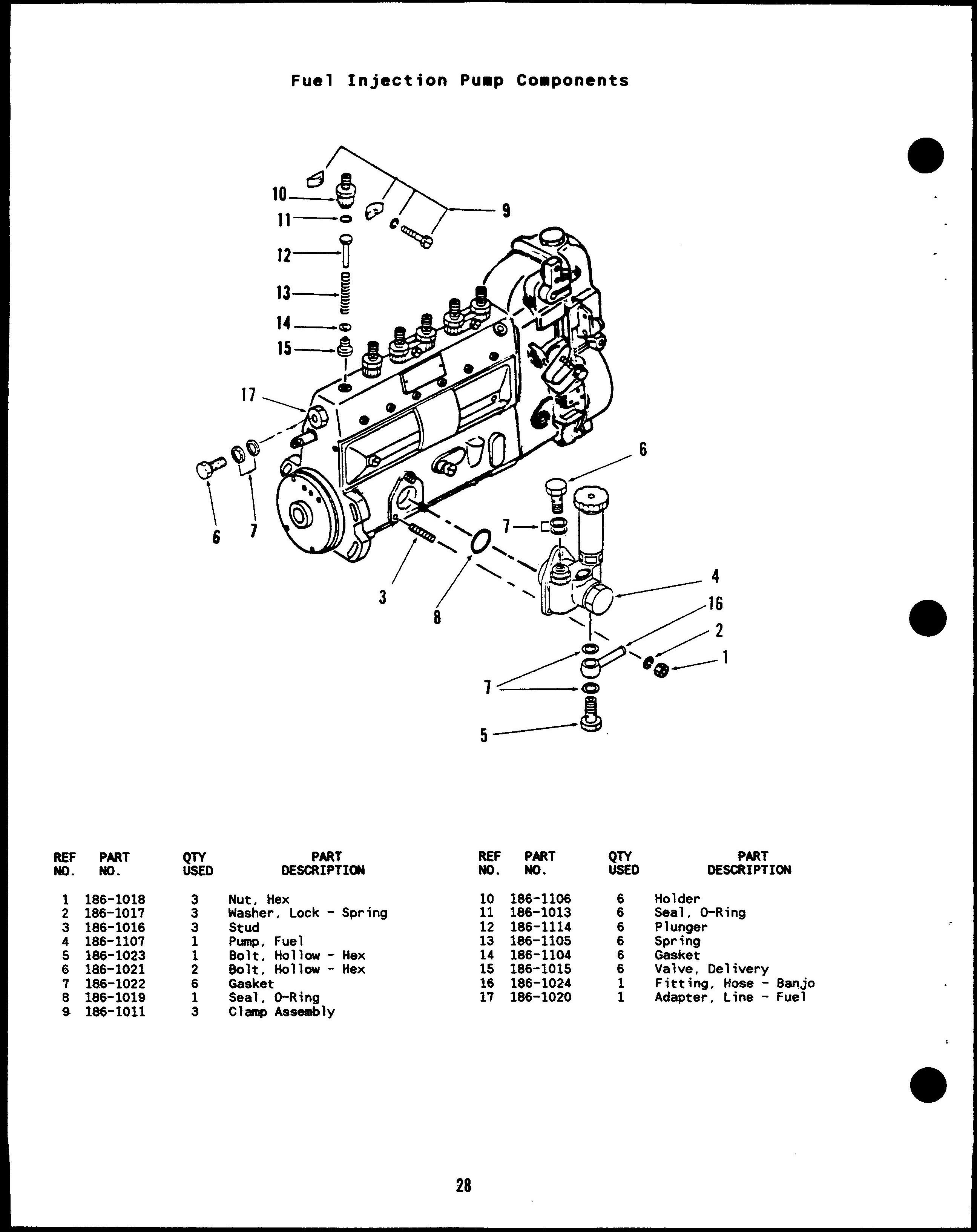
$’TTO PART DESCRIPTION Holder Seal, O-Ring Plunger Spring Gasket Valve, Delivery Fitting, Hose - 8anjo Adapter, Line - Fuel
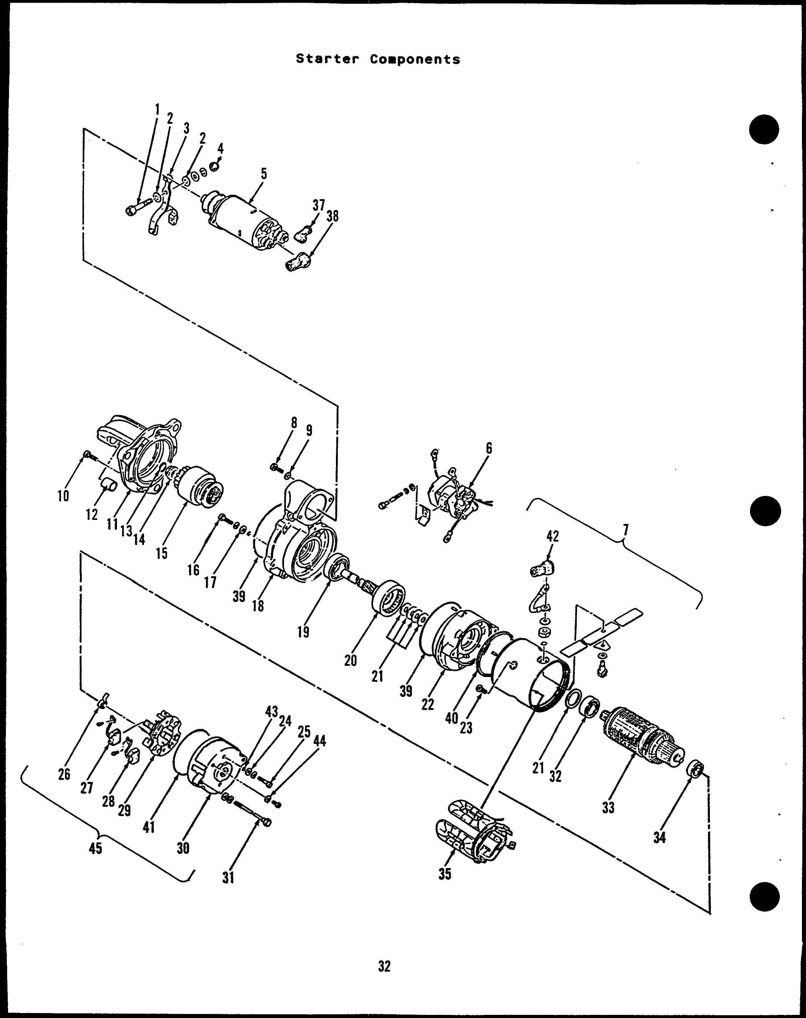
Lever - Threaded
Lever, Shift Nut, Hex Solenoid Switch Terminal Assembly (Does Not Include Rubber Cap) 8olt, Hex Head Washer, Lock - Spring Bolt, Hex Head Housing. Front 8ushing, Sleeve Ring, Retaining Stop, Pinon Clutch Bolt, Hex Head Washer, Flat 8racket, Center Bearing, 8all Shaft Washer Set, Thrust Bracket, Center Screw, Flat Head
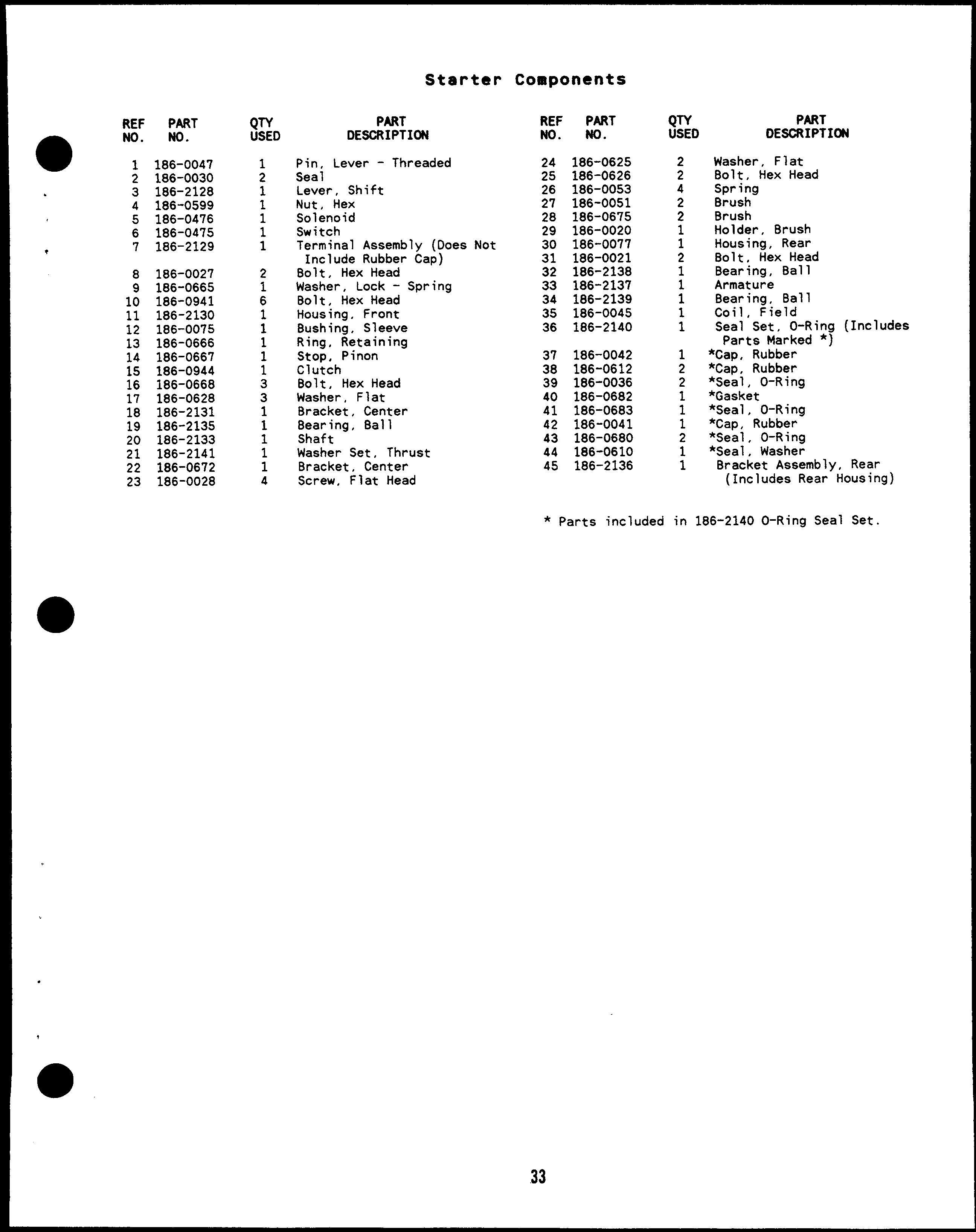
Bracket Assembly, Rear (Includes Rear Housing)
1
2
3
4
5
6
Flat
Screw, Cap - Hex Head ( 1/2 - 13 x 1-1/2”)
Washer, Lock (1/2)
Nut, Hex (1/2)
Bracket, Mounting - Governor
Screw, Cap - Hex Head (M6 x lx351nln)
Nut, Hex (M6)
Washer, Lock (MB)
Lever, Actuator
Screw (#10 - 32 x 3/4”)
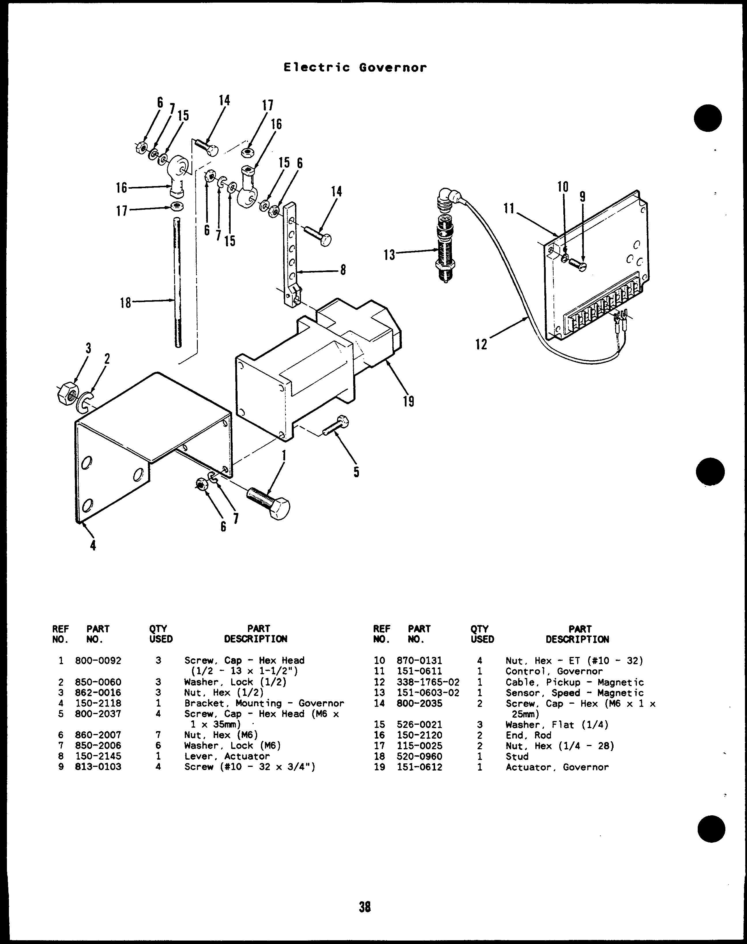
Nut, Hex - ET (#10 - 32)
Control, Governor Cable, Pickup - Magnetic Sensor, Speed - Magnetic Screw, Cap - Hex(M6xlx 25mm)
Washer, Flat (1/4)
End, Rod Nut, Hex (1/4 - 28’ Stud Actuator. Governor
Onan diesel generator, water pump, fan, water pump pulley, fan spacer, thermostat, temperature switches, temperature senders,
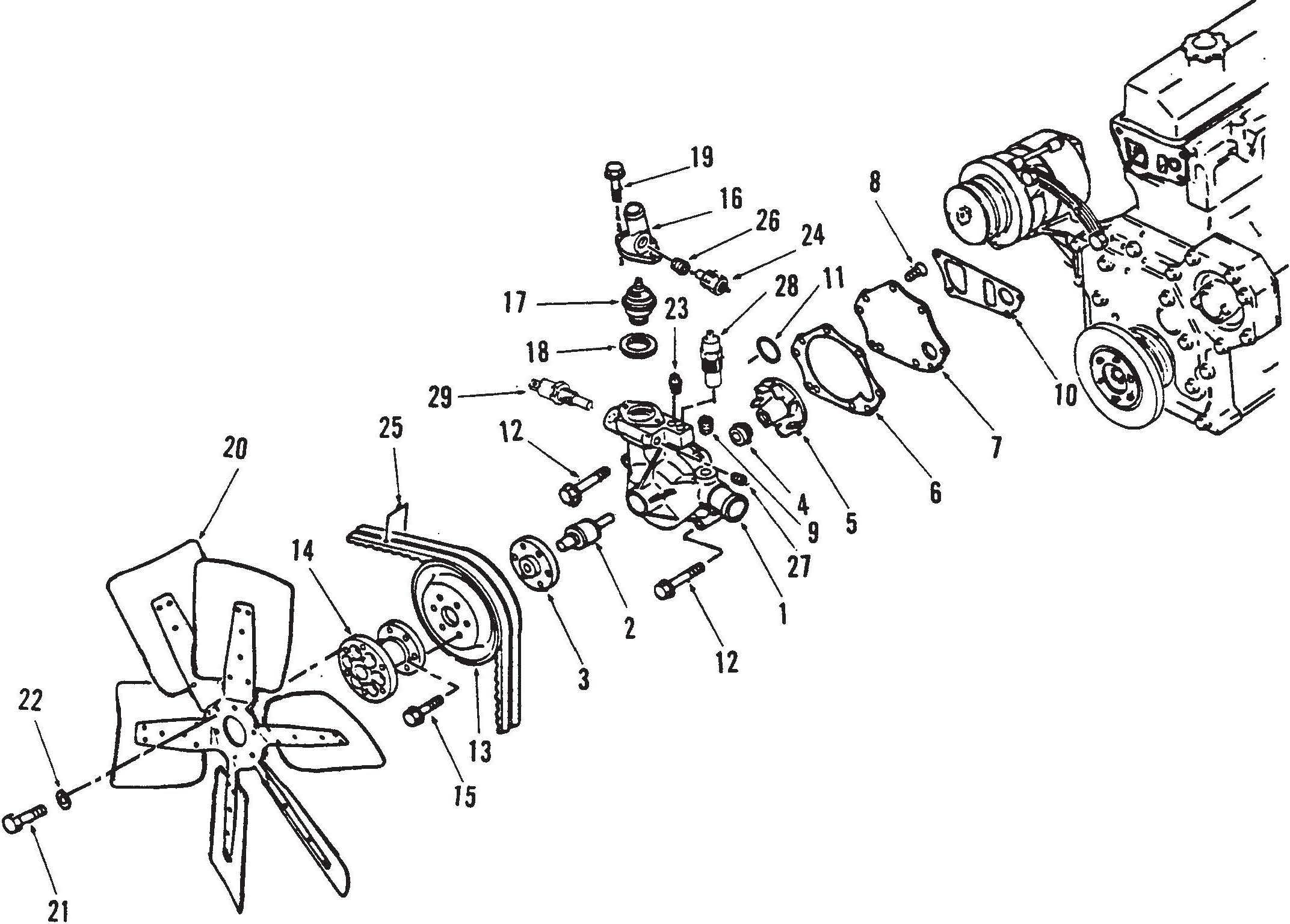
1. 186-0885 Water pump
2. 186-1025 Shaft
3. 186-1026 Spacer
4. 186-0886 Seal
5. 186-0887 Impellor
6. 186-0888 Cover
7. 186-0889 Gasket
8. 186-0890 Bolt (5)
9. 186-0488 Plug
10. 186-0891 Gasket
11. 186-0892 Seal
12. 186-0723 Bolt (4)
13. 186-0894 Pulley, water pump pulley,
14. 186-0896 Spacer, water pump to fan,
15. 186-0898 Bolt (6)

16. 186-0900 Housing, thermostat housing
17. 186-0901 Thermostat
18. 186-0902 Gasket, thermostat gasket,
19. 186-0827 Bolt, (2)
20. 186-2659 Fan, engine cooling fan,
21. 186-0756 Bolt, fan to spacer, (6)
22. 186-0904 Washer (6)
23. 186-0117 Plug
24. G1930318 Sender, coolant temperature, 25. G1860906 Belt Set, ( two belts )
26. 186-0907 Adapter
27. 186-0117 Plug
28. G3090521 Temperature Switch, high temperature warning,
29. 309-0522 Temperature Switch, high temperature shutdown,
Generator engine parts contact: email: engineparts2@gmail.com Phone: 269 673 1638
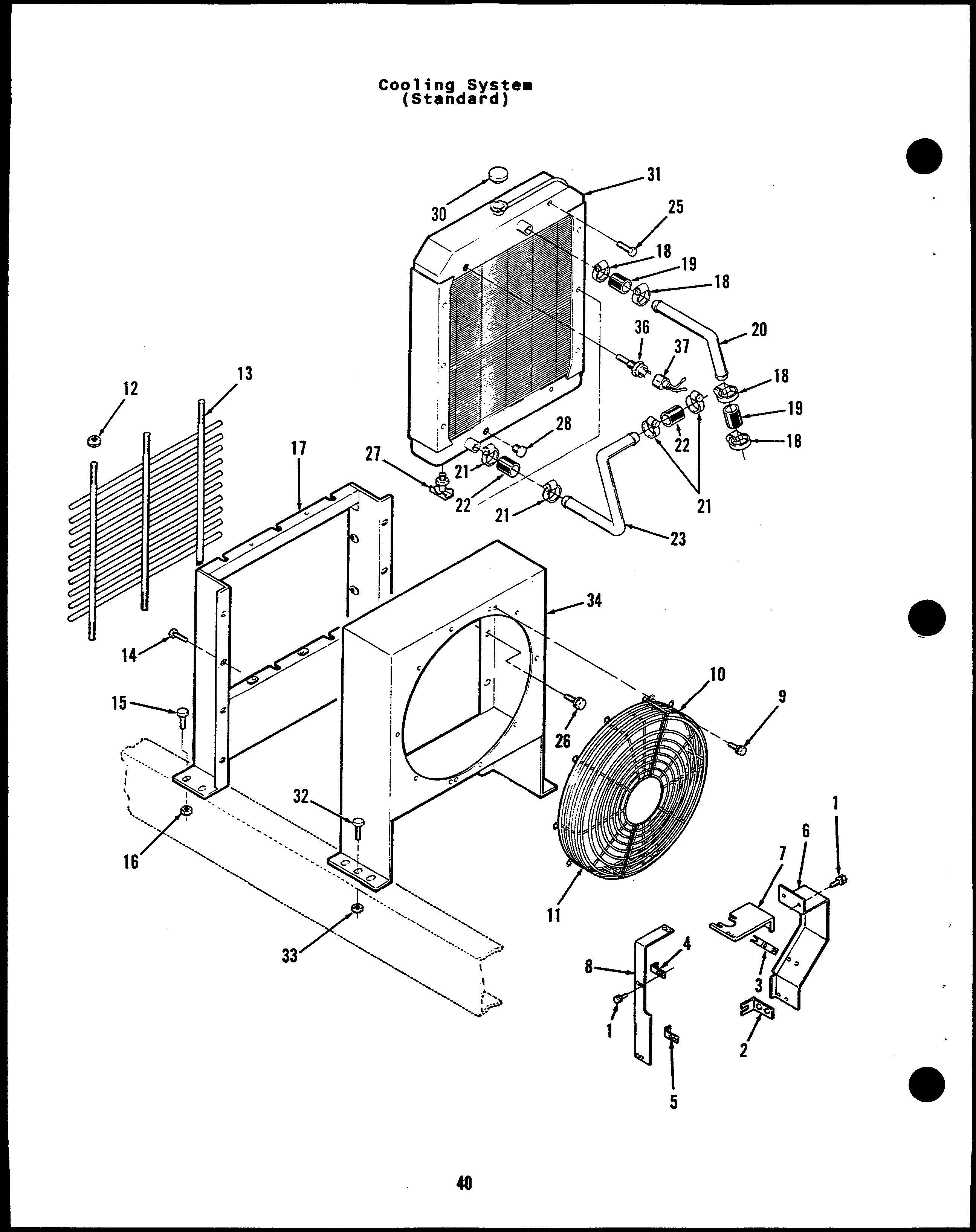
Screw, Self-Locking - Hex
Washer Hd (1/4 - 20 x 3/8”)
Bracket, Support - Belt Guard and Alternator Guard
Bracket, Support - Belt Guard and Alternator Guard
Bracket, Support - Belt Guard
Bracket, Support - Belt Guard
Guard, Belt (Less Brackets) Guard, Belt (Center)
Guard, Belt (Less Brackets)
Screw, Self-Locking - Hex
Washer Hd (1/4 - 20 x 5/8”)
Guard, Fan (Left Side)
Guard, Fan (Right Side)
Nut, Self-Locking - Hex
Washer Head (3/8 - 16)
Grille
Screw, Self-Locking - Hex Washer Hd (1/4 - 20 x 1/2”)
Screw, Self-Locking - Hex
Washer Hd (3/8 - 16 x 3/4”)
Nut, Self-Locking - Hex
Washer Head (3/8 - 16)
Guard, Radiator (Less Grille)
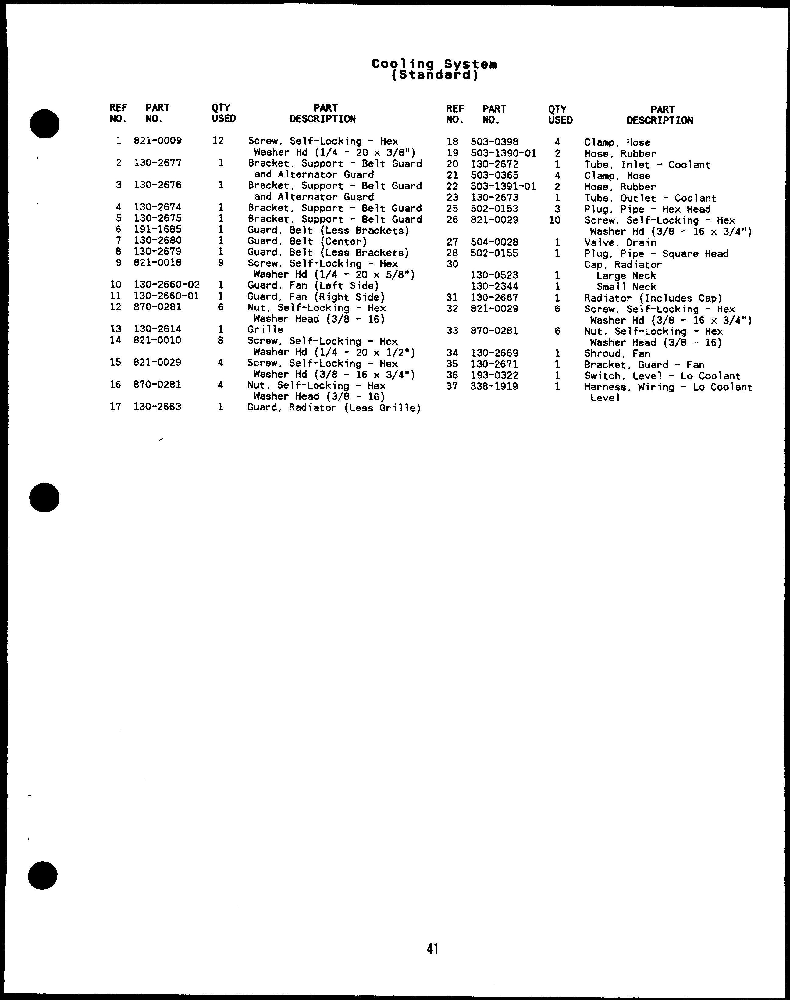
Clamp, Hose
Hose, Rubber Tube, Inlet - Coolant
Clamp, Hose Hose, Rubber Tube, Outlet - Coolant
Plug, Pipe - Hex Head
Screw, Self-Locking - Hex
Washer Hd (3/8 - 16 x 3/4”)
Valve, Drain
Plug, Pipe - Square Head
Cap, Radiator
Large Neck
Small Neck
Radiator (Includes Cap)
Screw, Self-Locking - Hex Washer Hd (3/8 - 16 x 3/4”)
Nut, Self-Locking - Hex Washer Head (3/8 - 16)
Shroud, Fan
Bracket, Guard - Fan
Switch, Level - Lo Coolant
Harness, Wiring - Lo Coolant Leve 1
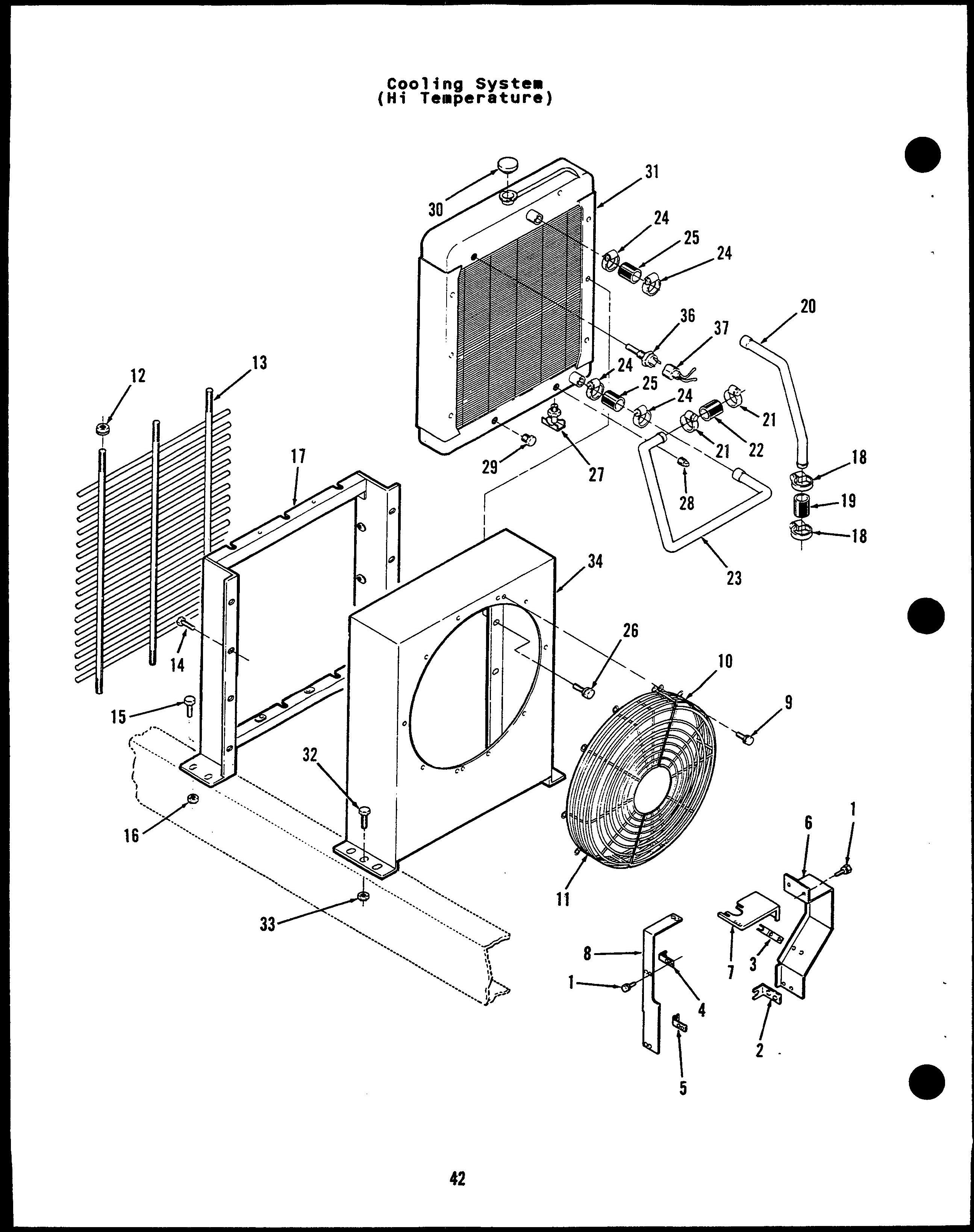
Screw, Self-Locking - Hex
Washer Hd (1/4 - 20 x 3/8”)
Bracket, Support - Belt Guard and Alternator Guard
Bracket, Support - Belt Guard and Alternator Guard
Bracket, Support - Belt Guard
Bracket, Support - Belt Guard
Guard, Belt (Less Brackets) Guard, Belt (Center)
Guard, Belt (Less Brackets)
Screw, Self-Locking - Hex
Washer Hd (1/4 - 20 x 5/8”)
Guard, Fan (Left Side)
Guard, Fan (Right Side)
Nut, Self-Locking - Hex
Washer Head (3/8 - 16)
Grille
Screw, Self-Locking - Hex
Washer Hd (1/4 - 20 x 1/2”)
Screw, Self-Locking - Hex
Washer Hd (3/8 - 16 x 3/4”)
Nut, Self-Locking - Hex
Washer Head (3/8 - 16)
Guard, Radiator (Less Grille)
Clamp, Hose
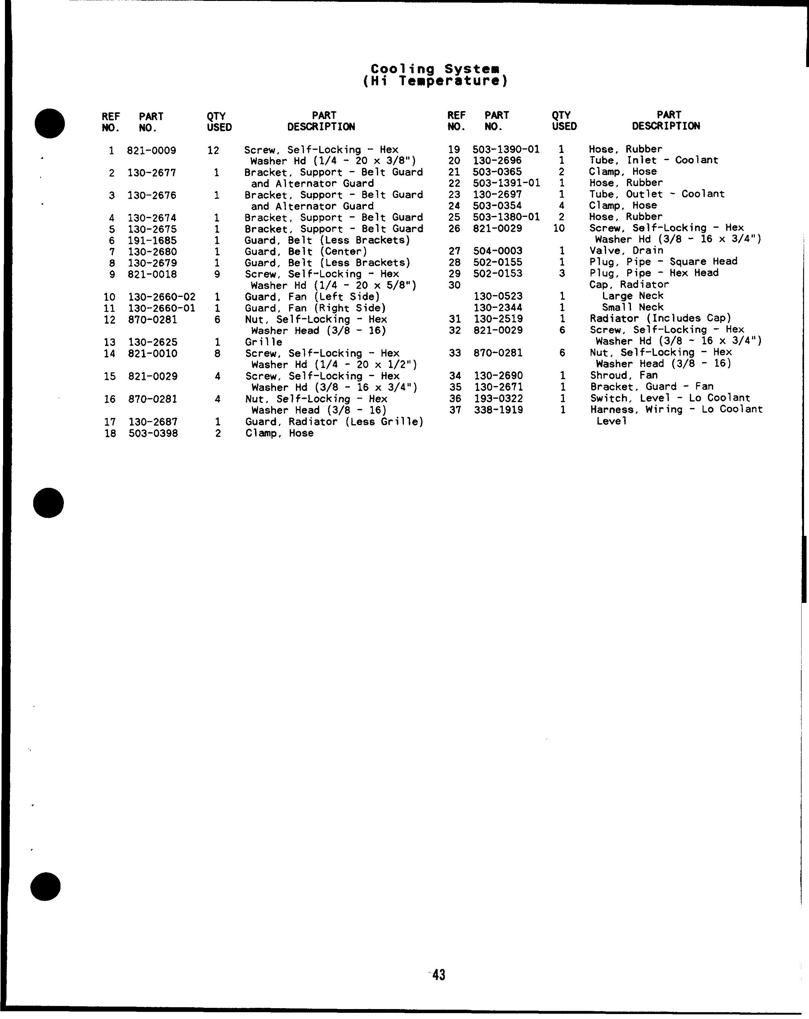
Hose, Rubber
Tube, Inlet - Coolant
Clamp, Hose
Hose, Rubber
Tube, Outlet - Coolant
Clamp, Hose
Hose, Rubber
Screw, Self-Locking - Hex
Washer Hd (3/8 - 16 x 3/4”)
Valve, Drain Plug, Pipe - Square Head
Plug, Pipe - Hex Head
Cap, Radiator
Large Neck
Small Neck
Radiator (Includes Cap)
Screw, Self-Locking - Hex
Washer Hd (3/8 - 16 x 3/4”)
Nut, Self-Locking - Hex
Washer Head (3/8 - 16)
Shroud, Fan
Bracket, Guard - Fan
Switch, Level - Lo Coolant
Harness, Wiring - Lo Coolant
Leve 1
Clamp, Hose Clamp, Hose Hose, Air
Indicator, Service - Air Adapter, Hex Head Tube, Air
Elbow, Rubber - 90”
Cap, Cleaner - Air
Screw, Machine - Fillister
Head (1/4 - 20 x l“)
Nut, Square (1/4 - 20) Cleaner Assembly, Air (Includes Element)
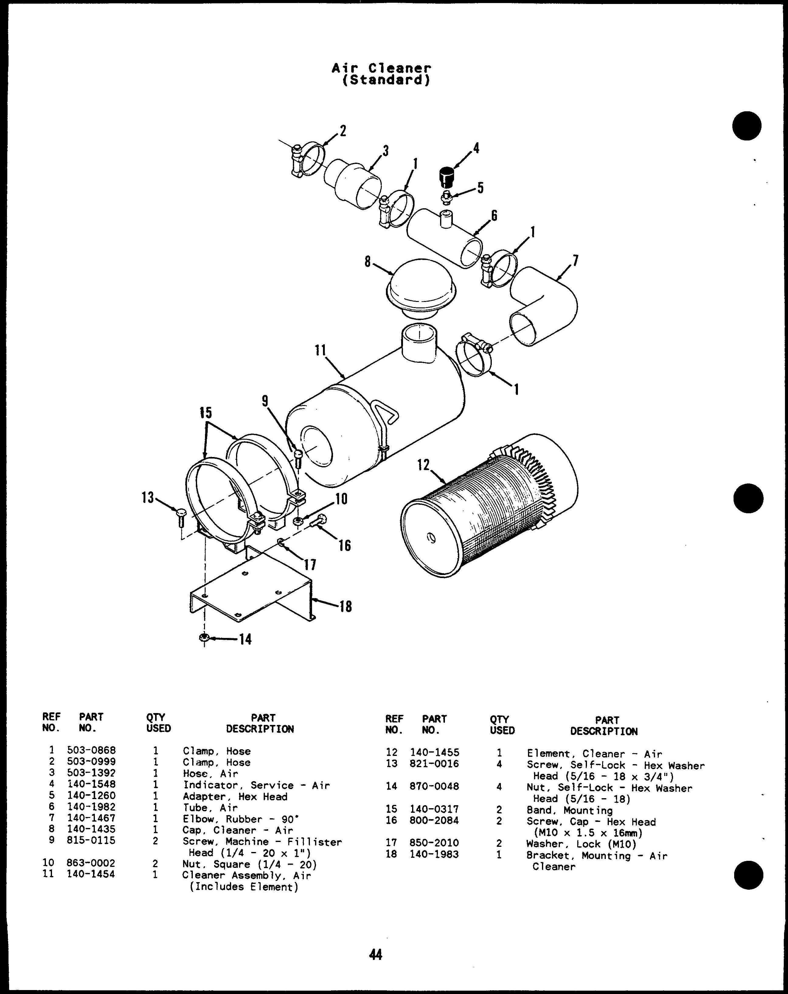
Element, Cleaner - Air
Screw, Self-Lock - Hex Washer Head (5/16 - 18 x 3/4”)
Nut, Self-Lock - Hex Washer Head (5/16 - 18)
8and, Mounting
Screw, Cap - Hex Head (M1O X 1.5 X 16mm)
Washer, Lock (M1O)
8racket, Mounting”- Air Cleaner
Hose - T-8olt Elbow, Reducing - 90” Screw, Cap - Hex Head (M1O X 1.5x 16mm) Washer, Lock (Mlo) 8racket, Mounting - Air
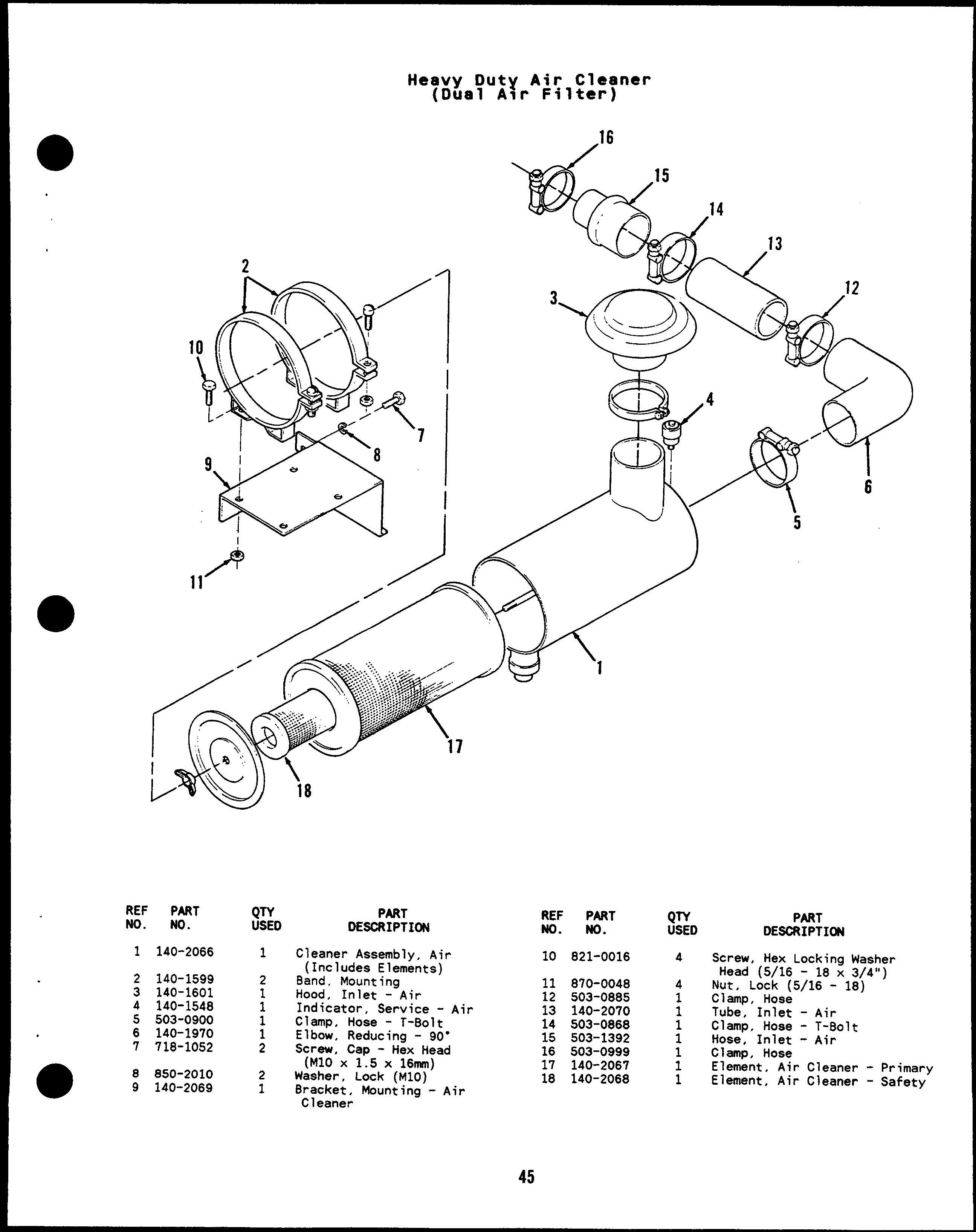
ClamD, Hose Tube”, Inlet- Air
Clamp, Hose - T-Bolt
Hose, Inlet - Air
Clamp, Hose
Element, Air Cleaner
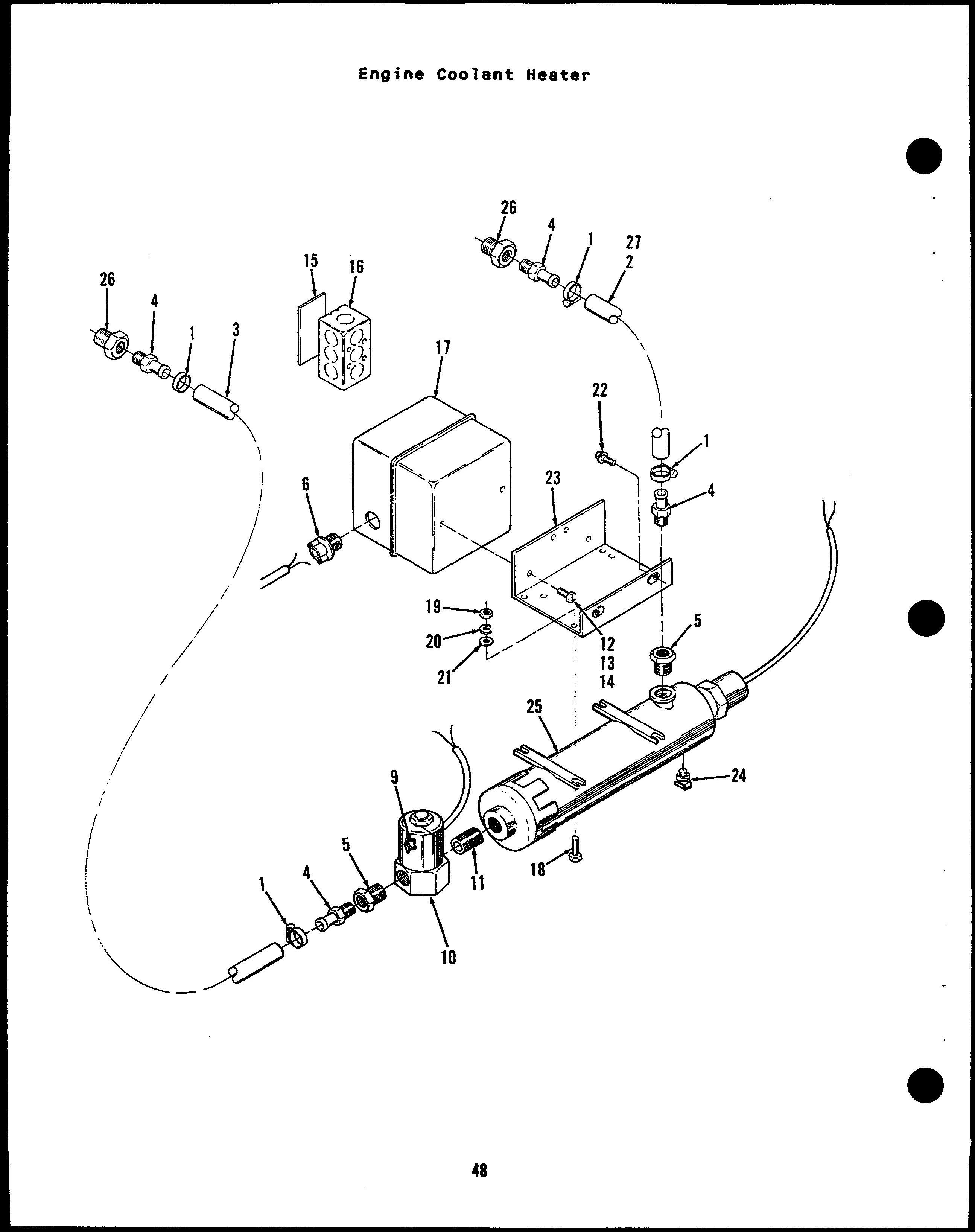
Hose Hose, Rubber Hose, Rubber Adapter, Hose Bushing, Reducer - Hex Clamp, Cable Terminal #10 (Used on White Leads) #8 (Used on White Leads) Nut, Wire (Used on 81ack Leads)
Switch, Thermostatic Nipple, Pipe - Close Screw, Mach - Round Head (#10- 24x 1/2”) Washer, Lock - Spring (#IO) Nut, Hex (#10 - 24) Cover, 80X - Outlet 80X, Outlet - Electrical
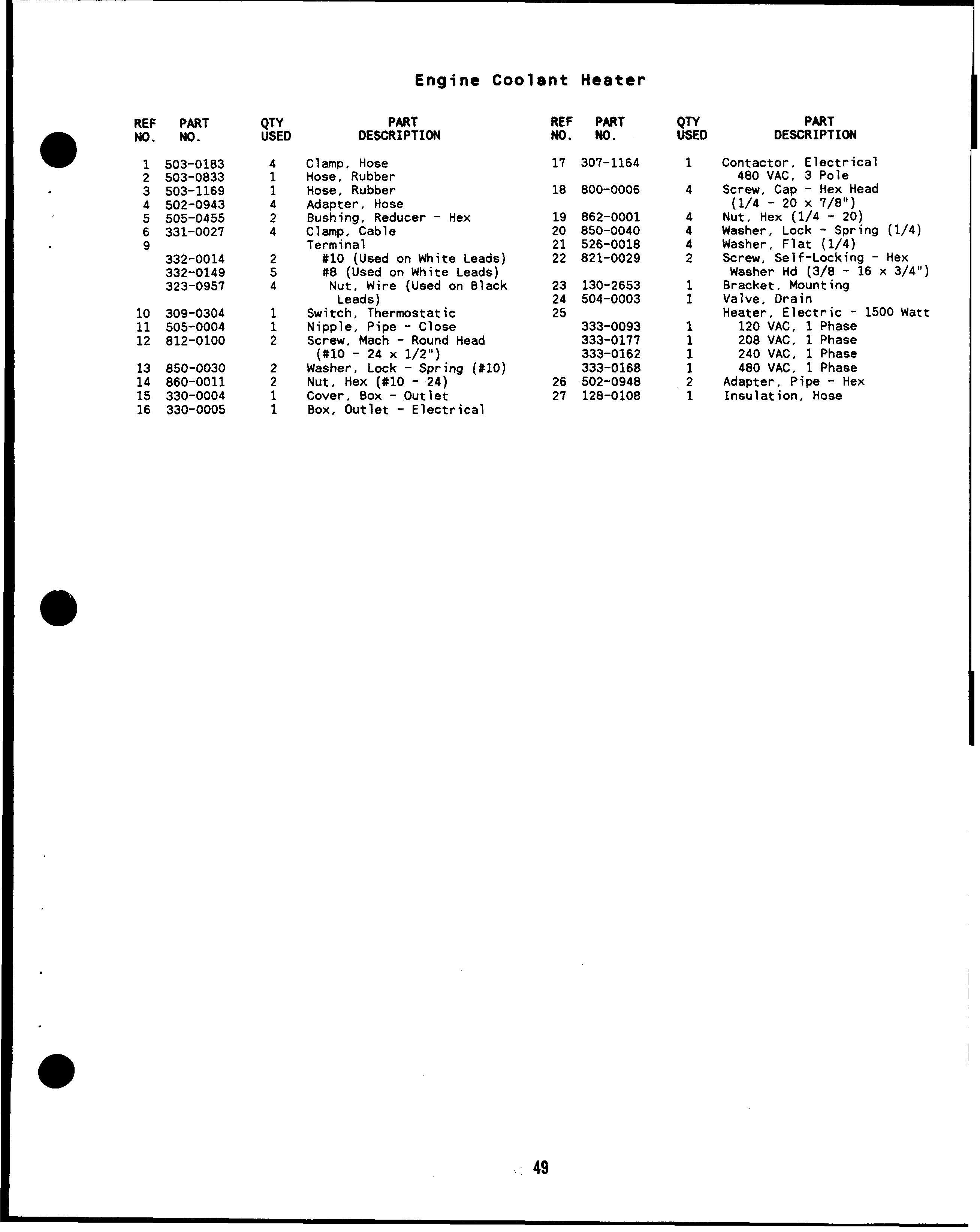
Contactor, Electrical 480 VAC, 3 Pole Screw, Cap - Hex Head (1/4 - 20x7/8”) Nut, Hex (1/4 - 20) Washer, Lock - Spring (1/4 Washer, Flat (1/4) Screw, Self-Locking - Hex Washer Hd (3/8 - 16 x 3/4 8racket, Mounting Valve. Drain ) Heate;, Electric - 1500
Insulation, Hose
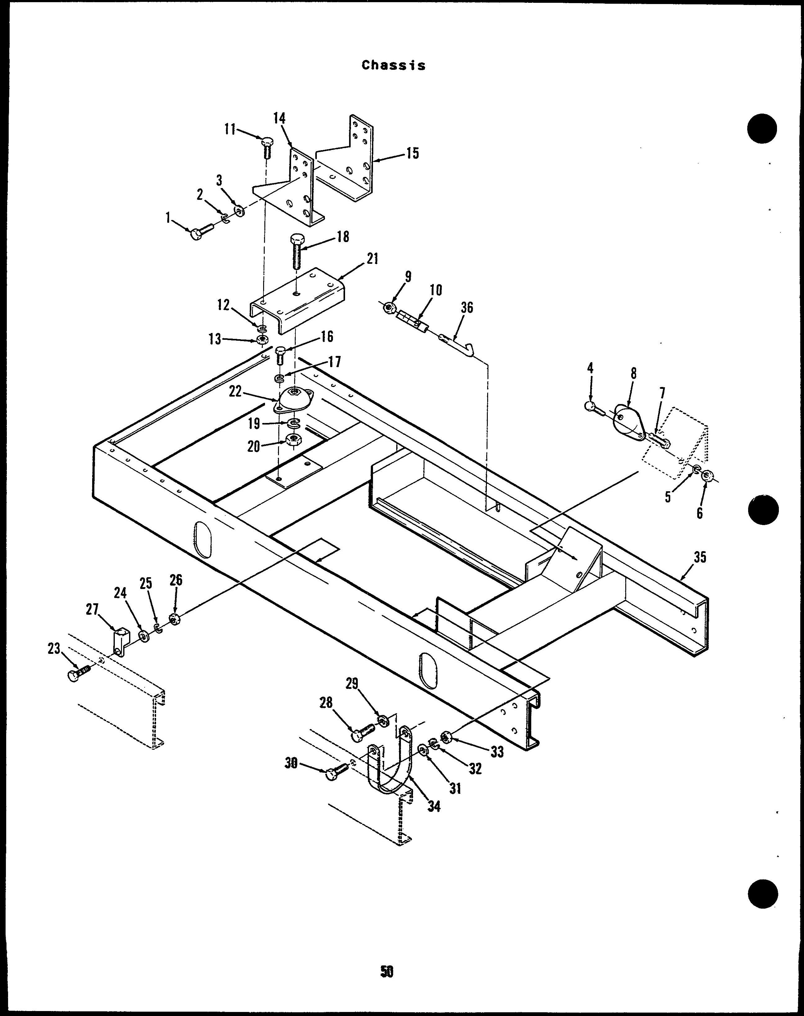
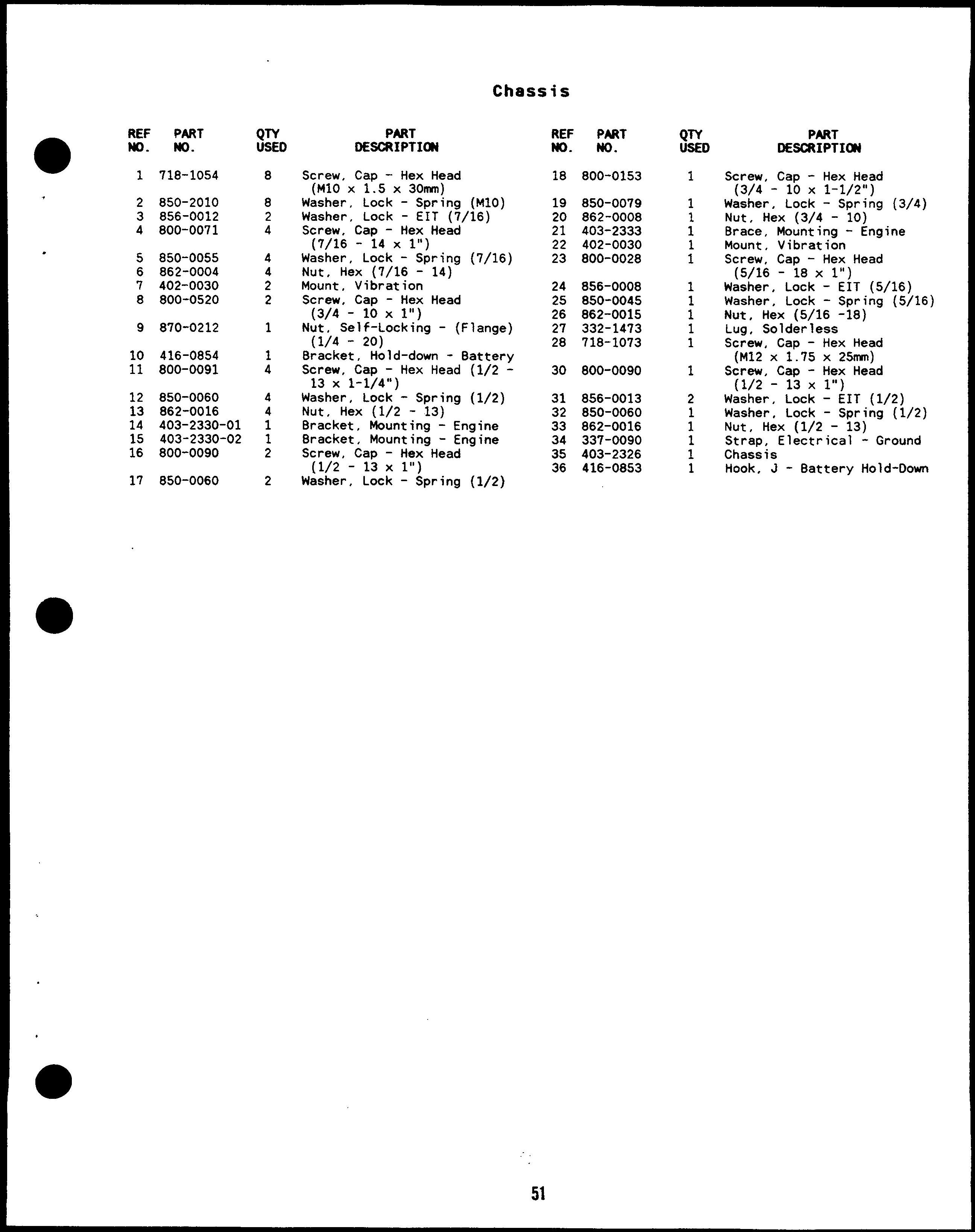
Screw, Cap - Hex Head (M1OX 1.5x 30nmn)
Washer, Lock - Spring (M1O)
Washer, Lock - EIT (7/16)
Screw, Cap - Hex Head (7/16 - 14 X 1“)
Washer, Lock - Spring (7/16) Nut, Hex (7/16 - 14)
Mount, Vibration
Screw, Cap - Hex Head (3/4 - lox l“) Nut, Self-Locking - (Flange) (1/4 - 20)
Bracket, Hold-down - Battery
Screw, Cap - Hex Head (1/213 x 1-1/4”)
Washer, Lock - Spring (1/2) Nut, Hex (1/2 - 13)
Bracket, Mounting - Engine
Bracket, Mounting - Engine
Screw, Cap - Hex Head (1/2 - 13X 1“)
Washer, Lock - Spring (1/2)
REF PART MO. No. lB 800-0153 19 850-0079 20 862-0008
403-2333
402-0030
800-0028 24 B56-0008
850-0045
862-0015
332-1473
71B-1073 30 800-0090
B56-0013
B50-0060
862-0016
416-0853 PART DE=IPTI~
Screw, Cap - Hex Head (3/4 - 10 x 1-1/2”)
Washer, Lock - Spring (3/4) Nut, Hex (3/4 - 10)
Brace, Mounting - Engine Mount, Vibration
Screw, Cap - Hex Head (5/16 - lBx l“)
Washer, Lock - EIT (5/16)
Washer, Lock - Spring (5/16) Nut, Hex (5/16 -18)
Lug, Solderless
Screw, Cap - Hex Head (M12 X 1.75x 25nnn)
Screw, Cap - Hex Head (1/2 - 13X l“)
Washer, Lock - EIT (1/2)
Washer, Lock - Spring (1/2) Nut, Hex (1/2 - 13)
Strap, Electrical - Ground
Chassis
Hook, J - Battery Hold-Down
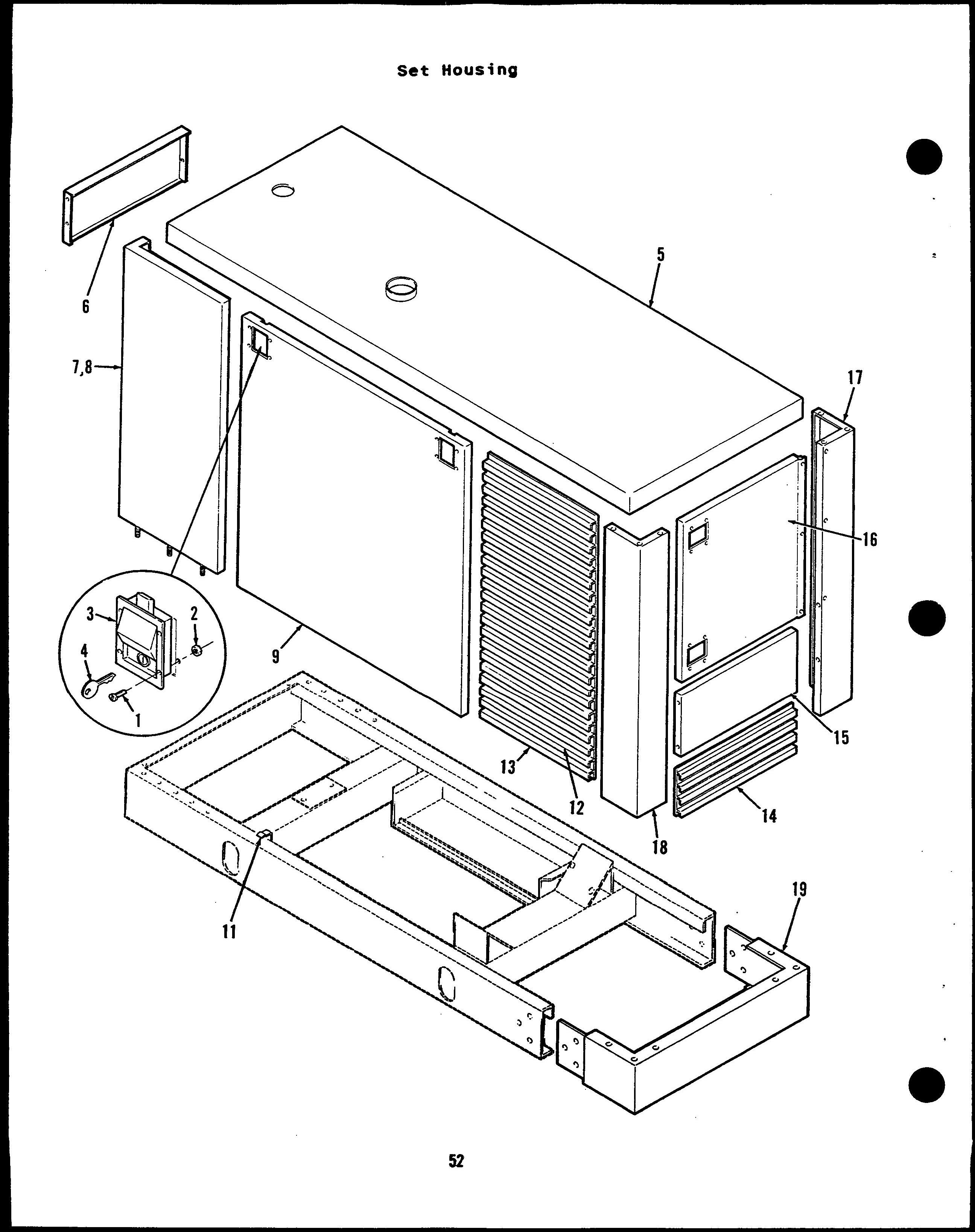
870-0281
405-3377-04 405-3377-05 821-0010
870-0212
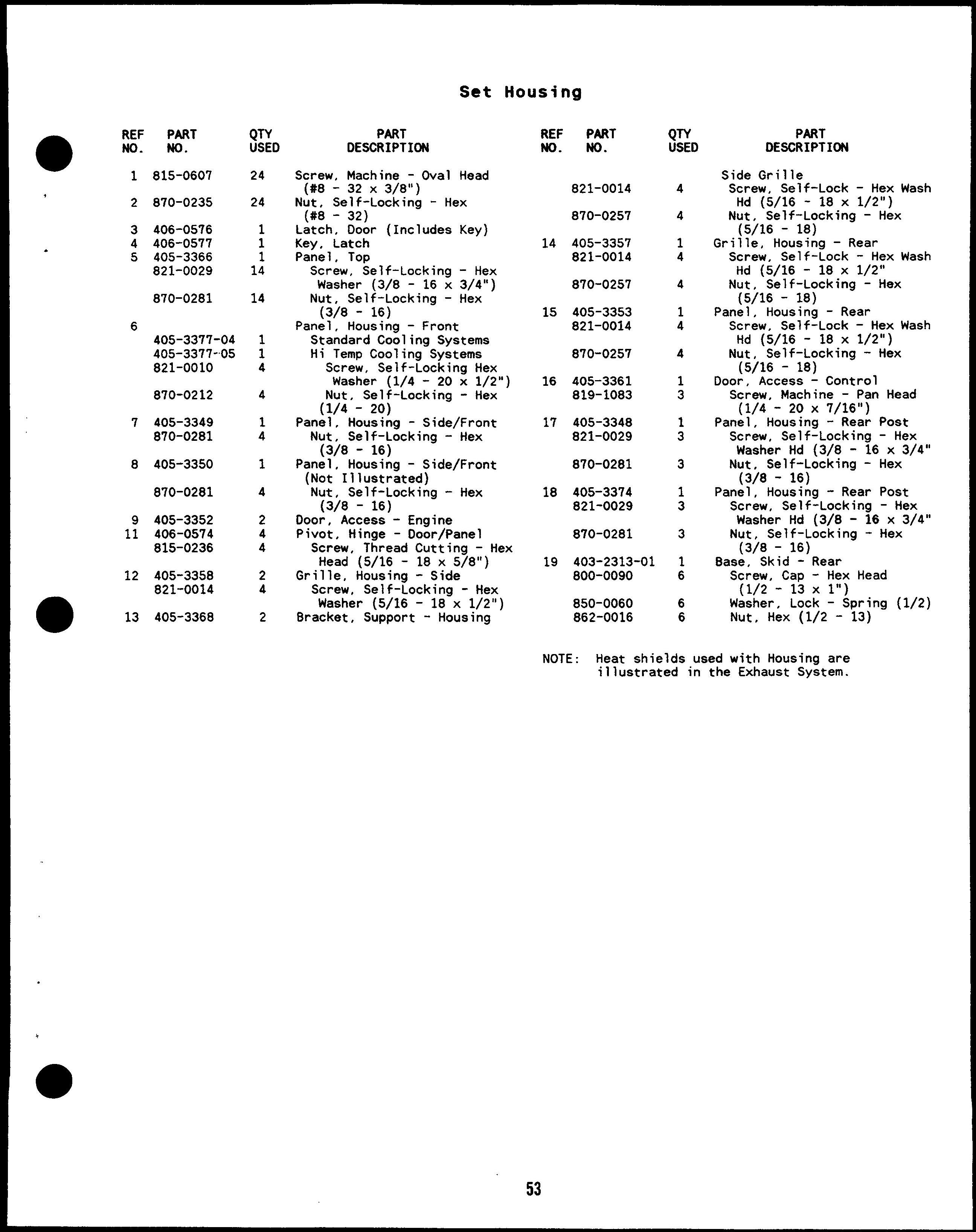
Screw, Machine - Oval Head (#8 - 32 x3/8”)
Nut, Self-Locking - Hex (#8 - 32)
Latch, Door (Includes Key)
Key. Latch
Panel, Top
Screw, Self-Locking - Hex
Washer (3/8 - 16 x 3/4”)
Nut, Self-Locking - Hex pan~/8 - 16)
Housing - Front
Standard Cooling Systems
Hi Temp Cooling Systems
Screw, Self-Locking Hex
Washer (1/4 - 20 x 1/2”)
Nut, Self-Locking - Hex (1/4 - 20)
Panel, Housing - Side/Front
Nut, Self-Locking - Hex (3/8- 16)
Panel, Housing - Side/Front (Not Illustrated)
Nut, Self-Locking - Hex (3/8 - 16)
Door, Access - Engine
Pivot, Hinge - Door/Panel
Screw, Thread Cutting - Hex Head (5/16 - 18 x 5/8”)
Grille, Housing - Side
Screw, Self-Locking - Hex Washer (5/16 - 18 x 1/2”)
Bracket, Support - Housing
821-0014
870-0257
405-3357 821-0014
870-0257
405-3353 821-0014
870-0257 16 405-3361 819-1083
405-3348 821-0029
870-0281 18 405-3374 821-0029
870-0281 19 403-2313-01 800-0090 850-0060 862-0016
Side Grille Screw, Self-Lock Hd (5/16 - 18 X -
1/2”) Nut, “Self-Locking - Hex (5/16 - 18)
Grille, Housing - Rear Screw, Self-Lock - Hex Wash Hd (5/16 - 18 X 1/2” Nut, Self-Locking - Hex (5/16 - 18)
Panel, Housing - Rear Screw, Self-Lock - Hex Wash Hd (5/16 - 18 X 1/2”) Nut, Self-Locking - Hex (5/16 - 18)
Door, Access - Control Screw, Machine - Pan Head ( 1/4 - 20x 7/16”)
Panel, Housing - Rear Post Screw, Self-Locking - Hex Washer Hd (3/8 - 16 x 3/4” Nut, Self-Locking - Hex (3/8- 16)
Panel, Housing - Rear Post Screw, Self-Locking - Hex Washer Hd (3/8 - 16 x 3/4” Nut, Self-Locking - Hex (3/8- 16)
Base, Skid - Rear Screw, Cap - Hex Head (1/2 - 13 x l“) Washer, Lock - Spring (1/2) Nut, Hex (1/2 - 13)
NOTE: Heat shields used with Housina are illustrated in the Exhaust Sy;tem.
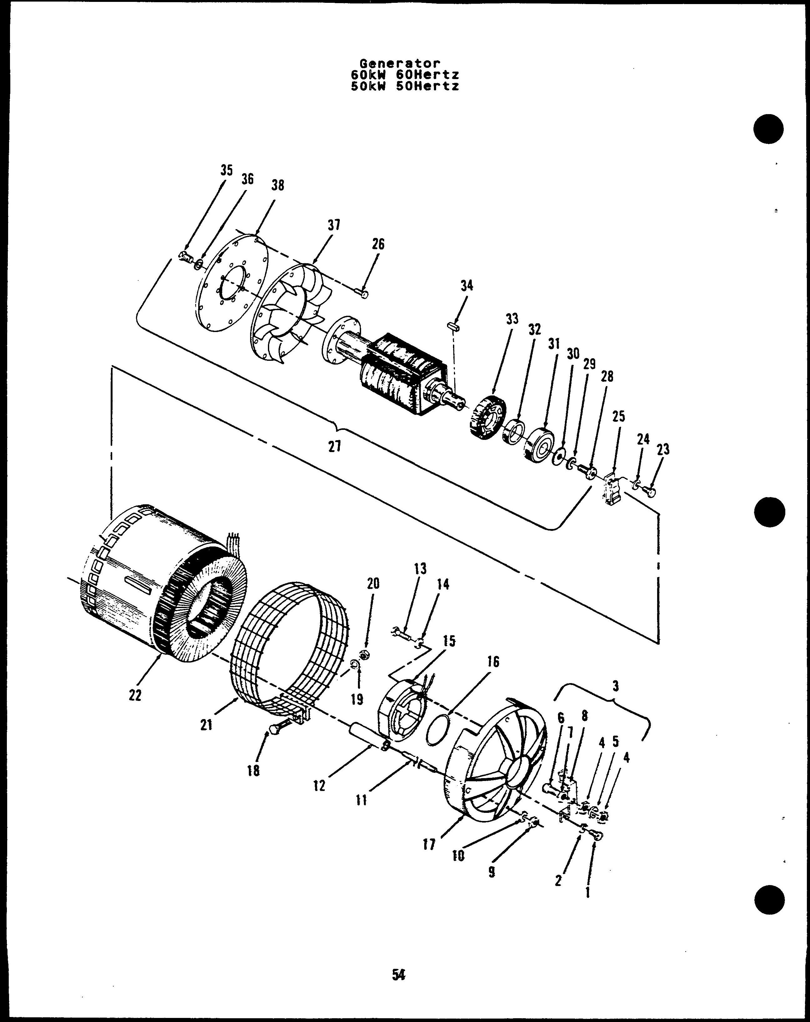
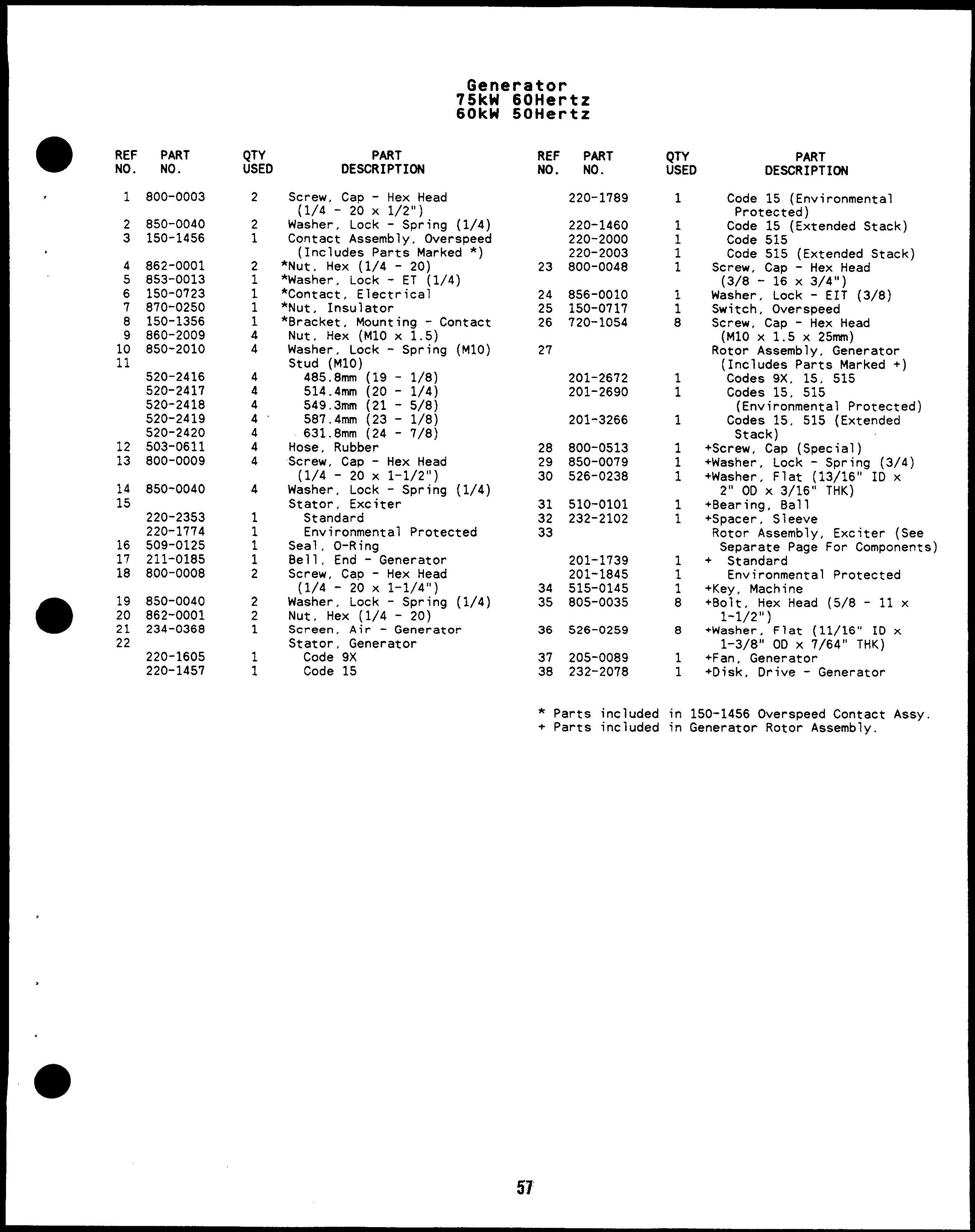
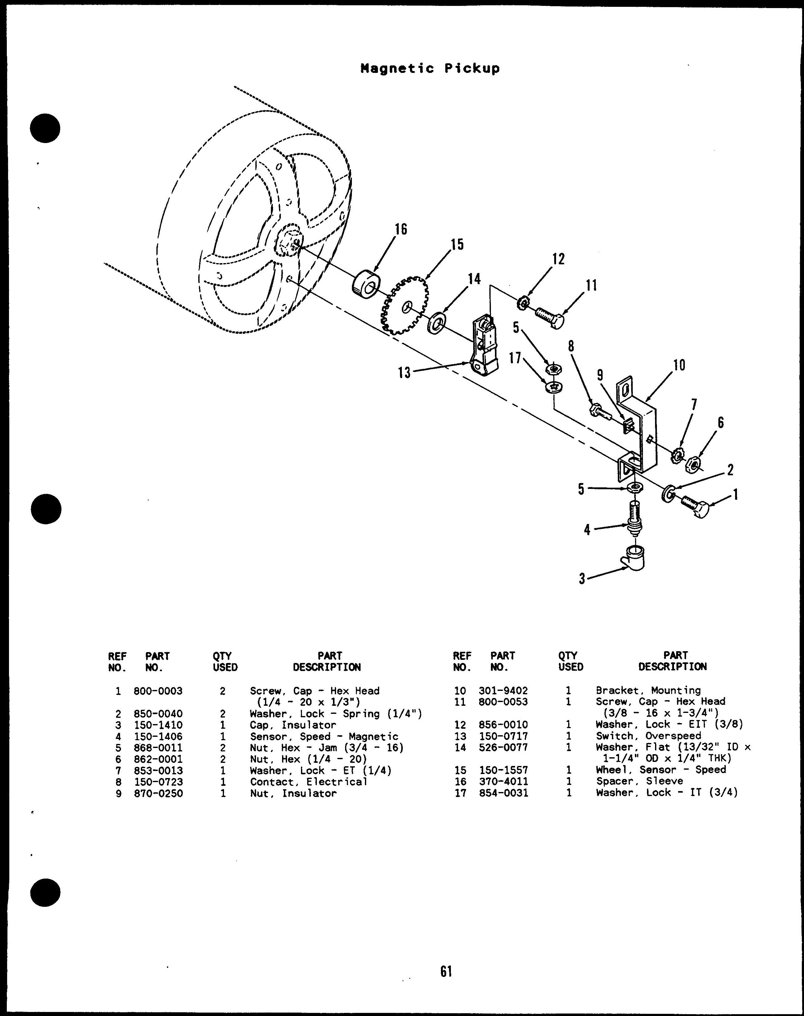
Screw, Cap - Hex Head ( 1/4 - 20 x 1/2”)
Washer, Lock - Spring (1/4)
Contact Assembly, Overspeed (Includes Parts Marked *)
*Nut, Hex (1/4 - 20)
*Washer, Lock - ET (1/4)
*Contact, Electrical
*Nut, Insulator
*Bracket, Mounting - Contact
Nut, Hex (M1O x 1.5)
Washer, Lock - Spring
Stud (M1O)
460.4mm (18 - 1/8)
485.8mm (19 - 1/8)
514.4mm (20 - 1/4)
549.3mm (21 - 5/8)
Hose, Rubber
Screw, Cap - Hex Head (1/4 - 20X 1-1/2”)
Washer, Lock - Spring Stator, Exciter Standard
Environmental Protected Seal, O-Ring
8ell, End - Generator
Screw, Cap - Hex Head (1/4 - 20 x 1-1/4”)
Washer, Lock - Spring (1/4)
Nut, Hex (1/4 - 20)
Screen, Air - Generator
Stator, Generator Code 7
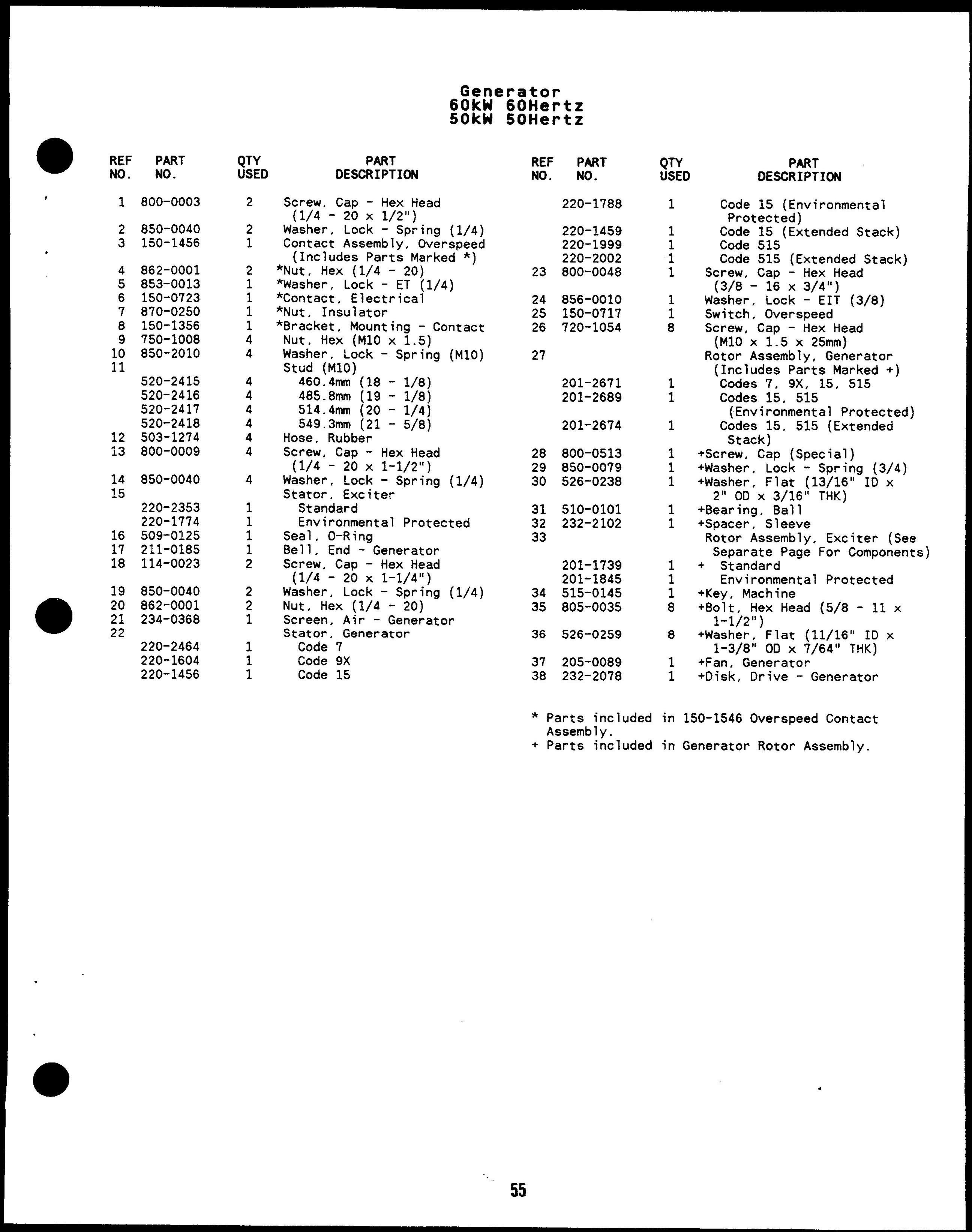
Code 15 (Environmental Protected)
Code 15 (Extended Stack)
Code 515
Code 515 (Extended Stack)
Screw, Cap - Hex Head (3/8- 16 x3/4”)
Washer, Lock - EIT (3/8)
Switch, Overspeed
Screw, Cap - Hex Head (M1OX 1.5 x 25mm)
Rotor Assembly, Generator (Includes Parts Marked +)
Codes 7, 9X, 15, 515
Codes 15, 515 (Environmental Protected) Codes 15, 515 (Extended Stack)
+Screw, Cap (Special)
+Washer, Lock - Spring (3/4)
+Washer, Flat (13/16” ID x 2“ OD X 3/16” THK)
+Bearing, Ball
+Spacer, Sleeve
Rotor Assembly, Exciter (See Separate Page For Components)
+ Standard Environmental Protected
+Key, Mach i ne
+Bolt, Hex Head (5/8 - 11 x 1-1/2”)
+Washer, Flat (11/16” ID x 1-3/8” OD X 7/64” THK)
+Fan, Generator
+Disk, Orive - Generator
* Parts included in Assembly.
+ Parts included in 150-1546 Overspeed Contact Generator Rotor Assembly.
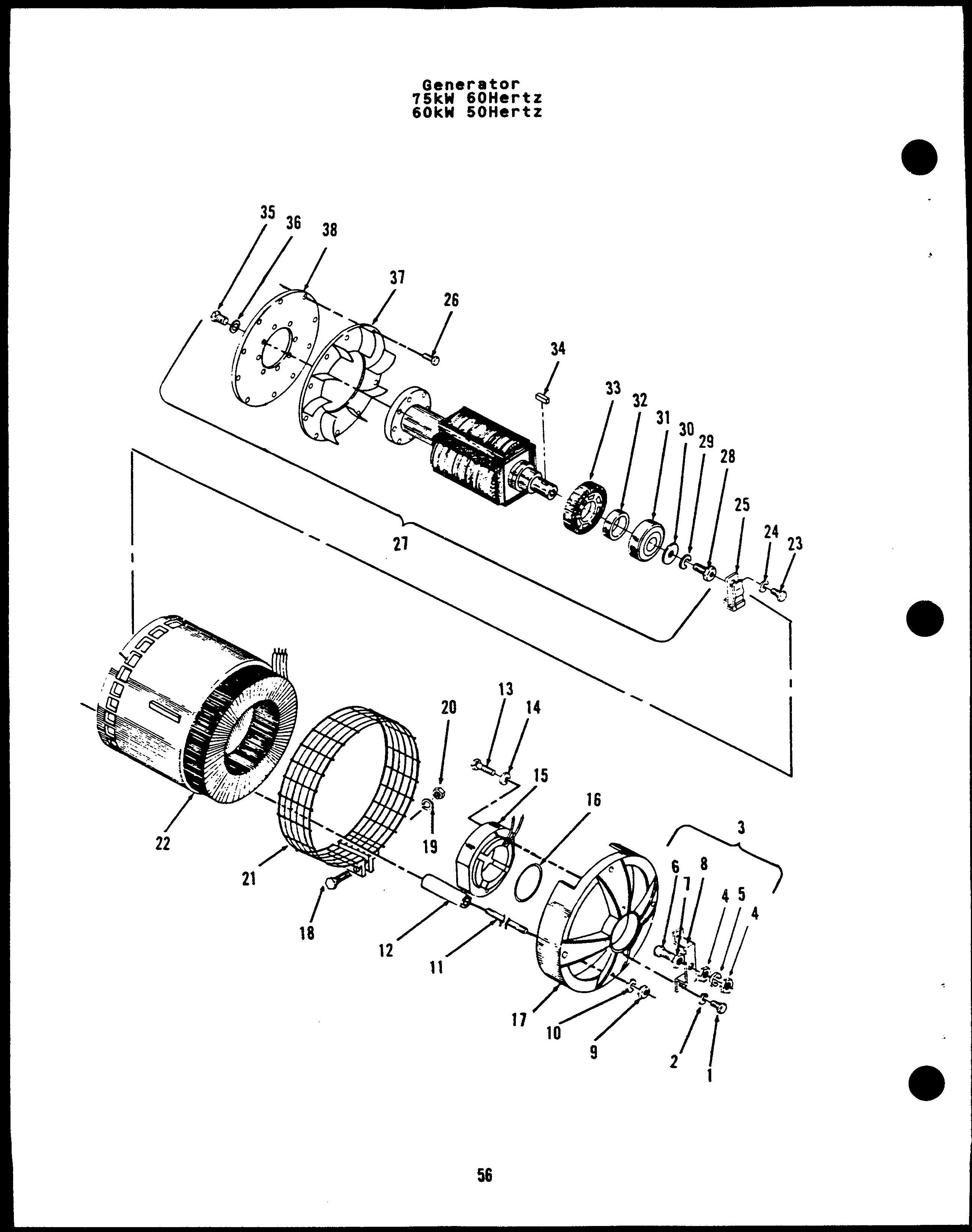
Screw, Cap - Hex Head (1/4 - 20X 1/2”)
Washer, Lock - Spring (1/4)
Contact Assembly, Overspeed (Includes Parts Marked *)
*Nut, Hex (1/4 - 20)
*Washer, Lock - ET (1/4)
*Contact, Electrical
*Nut, Insulator
*Bracket, Mounting - Contact Nut, Hex (M1O x 1.5)
Washer, Lock - Spring Stud (M1O)
485.8mm (19 - 1/8)
514.4mm (20 - 1/4)
549.3mm (21 - 5/8)
587.4mm (23 - 1/8)
631.8mm (24 - 7/8)
Hose, Rubber
Screw, Cap - Hex Head (1/4 - 20 x 1-1/2”)
Washer, Lock - Spring Stator, Exciter Standard (M1O) (1/4)
Environmental Proteci
Seal, O-Ring
Bell, End - Generator
Screw, Cap - Hex Head (1/4 - 20 x 1-1/4”)
Washer, Lock - Spring
Nut, Hex (1/4 - 20)
Screen, Air - Generator
Stator, Generator Code 9X Code 15 ed 1/4)
Code PART DESCRIPTION 15 (Environmental Protected)
Code 15 (Extended Stack) Code 515
Code 515 (Extended Stack)
Screw, Cap - Hex Head (3/8 - 16 x3/4”)
Washer, Lock - EIT (3/8) Switch, Overspeed Screw, Cap - Hex Head (M1O X 1.5 X 25mm)
Rotor Assembly, Generator (Includes Parts Marked +) Codes 9x, 15, 515 Codes 15, 515 (Environmental Protected) Codes 15, 515 (Extended Stack)
A Screw, Cap (Special)
1 +Washer, Lock - Spring (3/4)
1 +Washer, Flat (13/16” ID x 2“ OD X 3/16” THK) +Bearing, Ball : +Spacer, Sleeve
Rotor Assembly, Exciter (See Separate Page For Components)
1 + Standard 1 Environmental Protected 1 +Key, Machine
8 +801t, Hex Head (5/8 - 11 x 1-1/2”)
8 +Washer , Flat (11/16” IO x 1-3/8” OD X 7/64” THK)
1 +Fan, Generator
1 +Disk, Orive - Generator
* Parts included in 150-1456 Overspeed Contact Assy + Parts included in Generator Rotor Assembly.
Rotor Assembly - Exciter Standard Environmental Protected
Screw, Machine - Round Head (#lo - 32 X 1/2”)
Nut, Hex (#10 - 32)
Washer, Lock - Spring (#10)
Washer, Flat (13/64” ID x 7/16” 00 X 1/32” THK)
Screw, Machine - Round Head (#10 - 32x 2“)
Nut, Hex (#10 - 32)
Washer, Lock - Spring (#10)
Washer, Flat (7/32” ID x
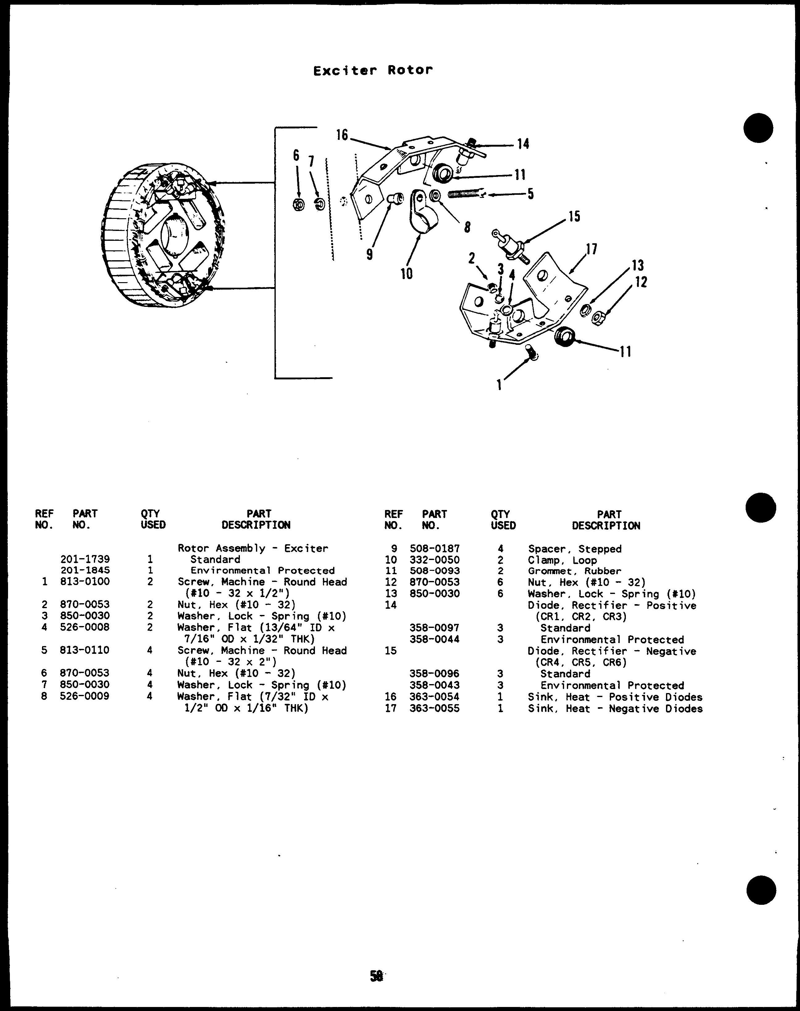
Spacer, Stepped Clamp, LOOFI
Gromnet, Rubber Nut, Hex (#10 - 32)
Washer, Lock - Spring (#10)
Diode, Rectifier - Positive (CR1, CR2, CR3) Standard Environmental Protected
Diode, Rectifier - Negative (CR4, CR5, CR6) ‘StandardEnvironmental Protected
Sink, Heat - Positive Diodes
Sink, Heat - Negative Diodes
(1/4)
Screw, Machine - Round Head
IT Washer ($6 - 32 x 1/2”)
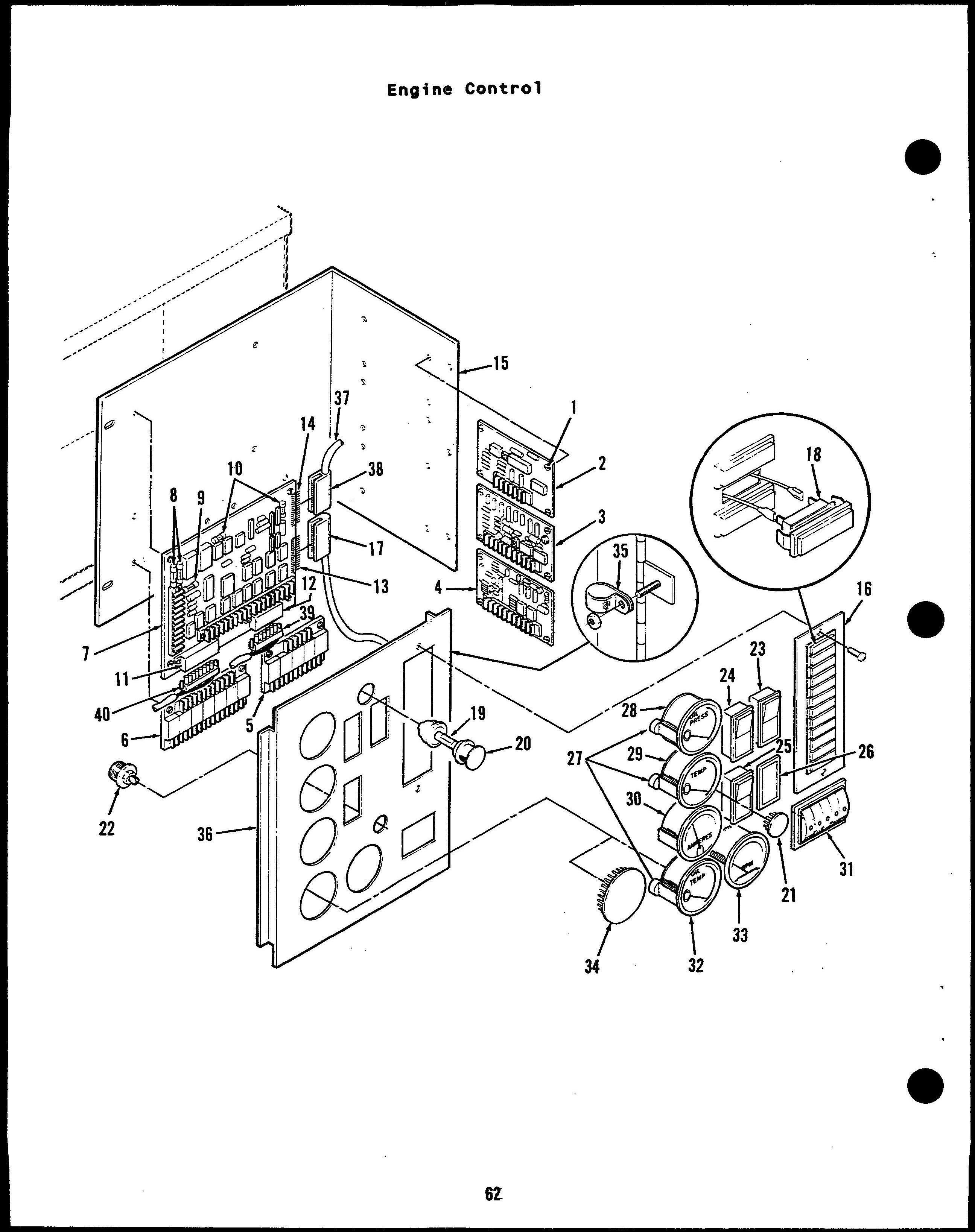
8oard Assy, Printed Circuit
Time Delay, Start/Stop (A15)
Board Assy, Printed CircuitMagnetic Pickup (A16) Standard (Fixed Sensitivity)
Precision (Adj Sensitivity)
Board Assy, Printed CircuitOver/Under Volt Sensor (A17)
Board Assy, Printed CircuitRelay Assembly - (A13)
Board Assy, Printed CircuitRelay Assembly - (A14)
Board Assy, Printed CircuitEngine Monitor - (All)
(IncludeaF uses & Connectors)
2 Light Control
7 Light Control
12 Light Control
Fuse, Cartridge - 20 Amp (Fl, F2)
Fuse, Cartridge - 15 Amp (F3)
Fuse, Cartridge - 5 Amp (F4, F5)
Connector - 8 Pin (Pi)
Connector - 6 Pin (P2)
Connector - 13 Pin (P3)
Connector - 12 Pin (P4)
Bracket, Mounting - Printed Circuit 8oard Assembly Screw, Self-Locking - Hex Washer Head (#10 - 32 x 5/16 “ )
Module, Indicator - Fault (A12) (Includes Connector Housing)
2 Light
Screw, Machine - Round Head (#6 - 32 x 1/2”) Nut, Self-Locking - ET Hex Washer Head (#6 - 32) Housing, Corm - 13 pin (J3)
Contact, Pin
Lamp, Incandescent - 1/3 Watt 28 Volts DC
Lamp, Incandescent - 28 Volts DC (DS1l)
Holder, Lamp
Plug, 8utton
Potentiometer - Speed Control (Rll)
Switch, Push - Reset/Panel LamP (S11)
Switch, Push - Run/Stop/ Remote (S12)
Cover, Hole - Switch
Resistor, Gauge (R12)
Gauge, Pressure - Oil (Mll)
Gauge, Temp - Water (M12)
Meter, Ampere - DC (M13)
Meter, Running Time (M14)
Gauge, Temp - Oil (M15)
Meter, Tach (M16)
Plug, 8utton
ClamP, LooP Nut, Self-Locking - ET Hex Washer Head (#10 - 32)
Door, Control
5 Gauge Holes
3 Gauge Holes
Harness, Wiring - DC (Includes Connector Housing)
Housing, Corm - 12 Pin (J4) Contact, Pin
*Housing, Corm - 6 Pin (J2)
* Contact, Pin
*Housing, Corm - 8 Pin (Jl)
* Contact, Pin
* Parts included in Control To Engine Wiring Harness.
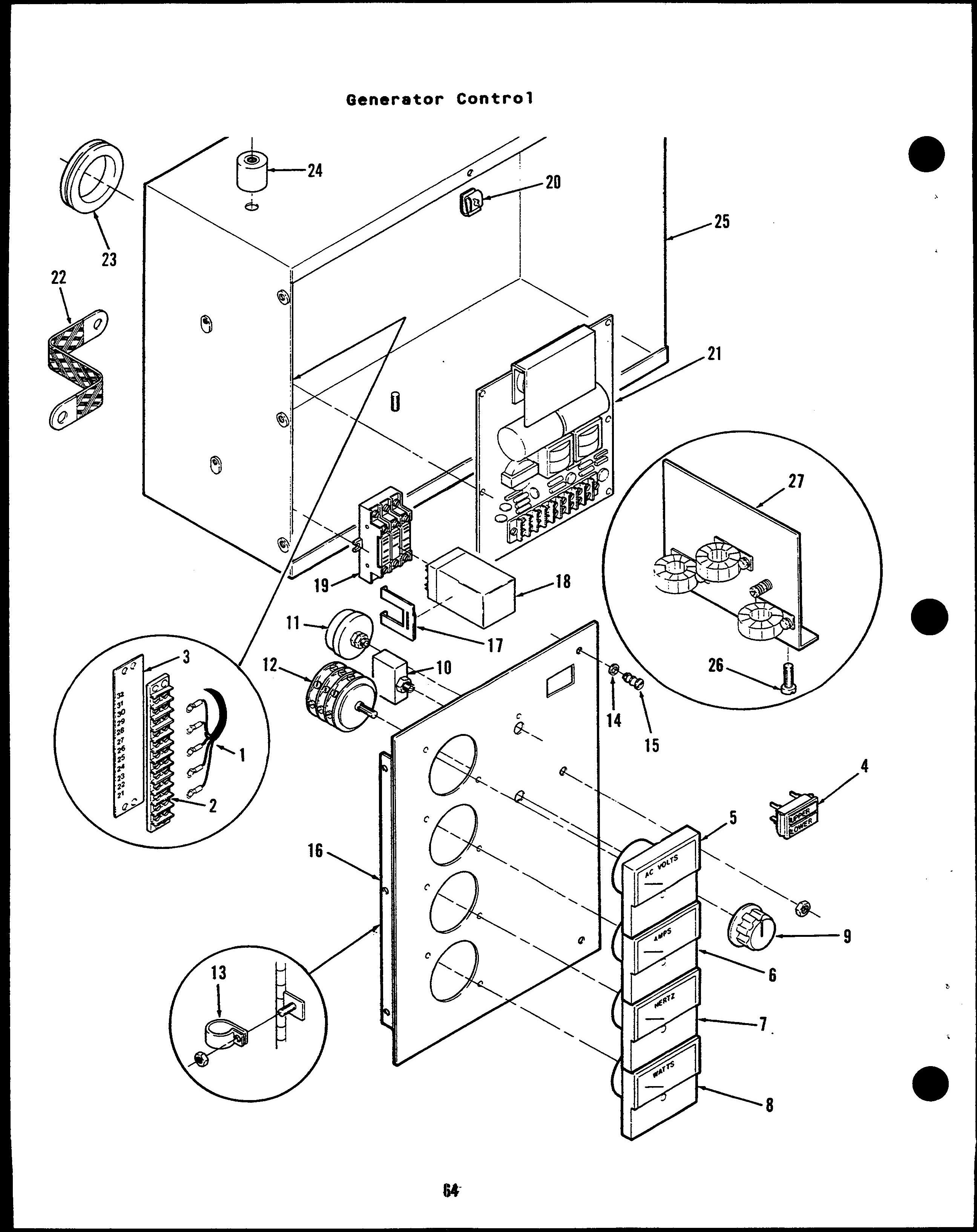
Harness, Wiring - AC (Includes Terminal 810ck) Controls With Meters Controls Without Meters Screw, Machine - Round Head (#6 - 32 x 5/8”) 810ck, Terminal (T81)
Strip, Marker
Light, Indicator - Dual (DS21, DS22)
Meter, Volt - AC (M21) Meter, Ampere - M22
Single Scale
0-100 Amp - 60, 75 kW (Voltage Code 9x) Dual Scale
0-150/300 Amp - 50, 60 kW (Voltage Code 7, 15, 515)
0-200/400 Amp - 75 kw (Voltage Code 15)
Meter, Frequency (M23) Meter, Watt (M24) (See Separate Page For Components) Knob
Breaker, Circuit (C821) Without Auxiliary Contacts With Auxiliary Contacts
Rheostat (R21)
Switch, Rotary (S21) ClamP, LooP Nut, Self-Locking - ET Hex Washer Head (#10 - 32)
Clip, Retaining - Turnbutton
Fastener -
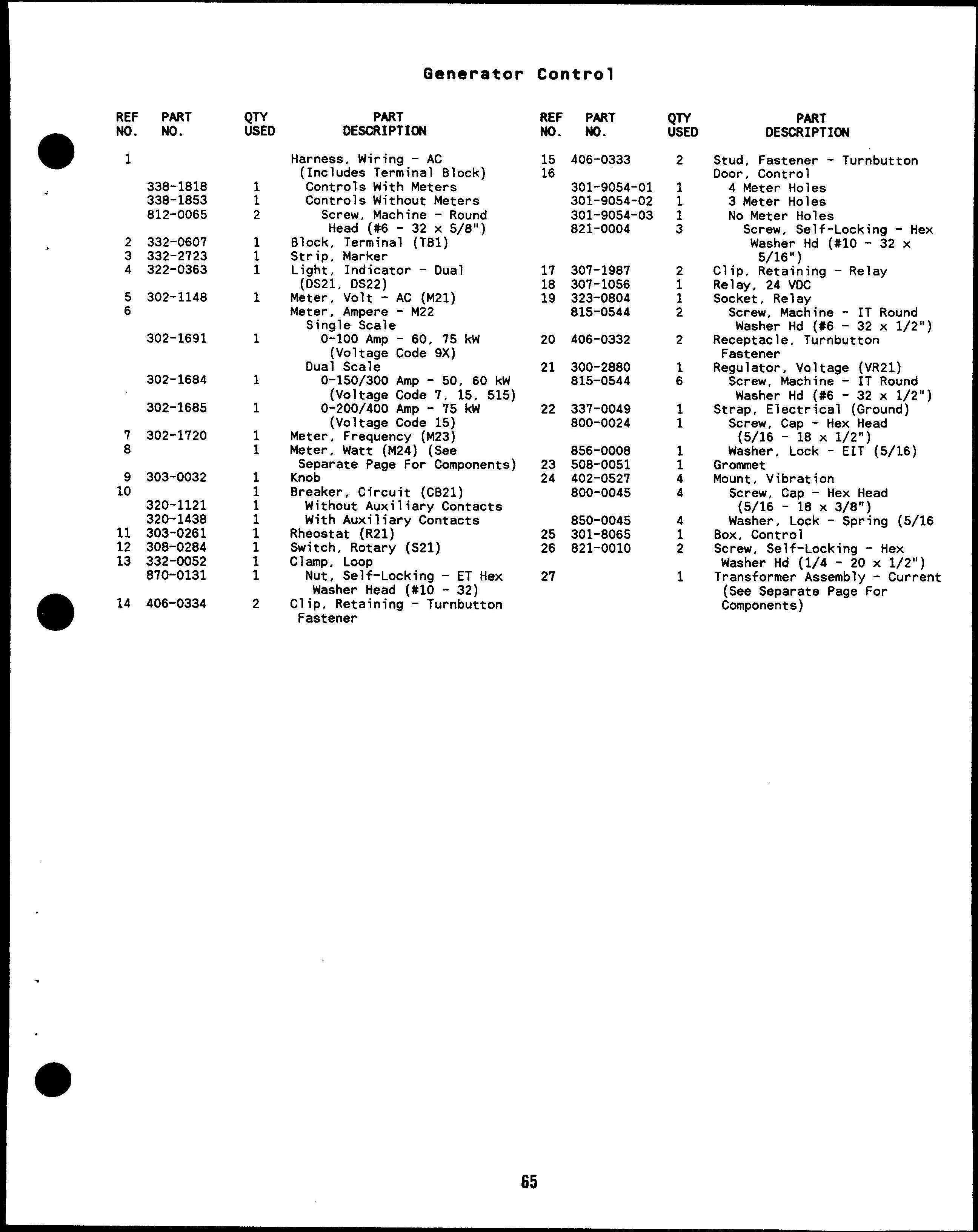
Stud, Fastener - Turnbutton
Door, Control 4 Meter Holes
3 Meter Holes No Meter Holes
Screw, Self-Locking - Hex Washer Hd (#10 - 32 x 5/16”)
Clip, Retaining - Relay
Relay, 24 VDC
Socket, Relay
Screw, Machine - IT Round
Washer Hd (#6 - 32 x 1/2”)
Receptacle, Turnbutton Fastener
Regulator, Voltage (VR21)
Screw, Machine - IT Round Washer Hd (#6 - 32 x 1/2”)
Strap, Electrical (Ground)
Screw, Ca~ - Hex Head (5/16 - i8 x 1/2”)
Washer. Lock - EIT (5/16)
Grommet
Mount, Vibration
Screw, CaD - Hex Head (5/16 - i8 X 3/8”)
Washer. Lock - .%ring (5/16
Box, Control ‘
Screw, Self-Locking - Hex Washer Hd (1/4 - 20 x 1/2”)
Transformer Assembly - Current (See Separate Page-For Components)
Terminal Assembly, Ground (Includes Parts Marked
‘Screw, Machine - Round Head Brass (#10 - 32 X 7/8”) Nut, Hex - Brass (#10 - 32)
Washer, Lock - EIT (#IO)
Washer, Lock - IT (#10)
Washer. Flat - Braas (13/64”i-x 7/32” ODX 1/32” THK)
Screw, Machine - Round Head (#lo - 32 X 2“)
Washer, Lock - IT (#10)
Clamp,
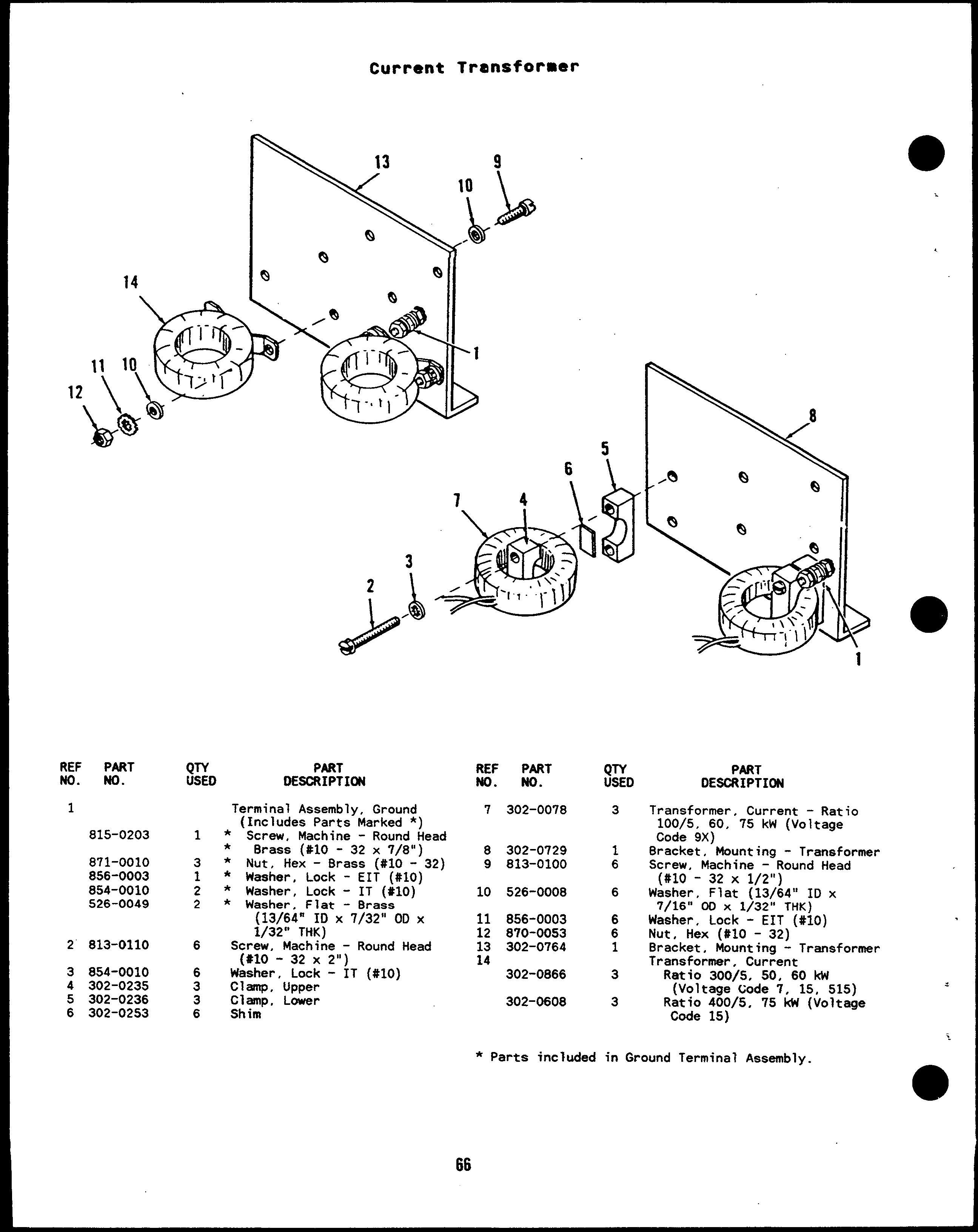
Transformer, Current - Ratio 100/5, 60, 75 kW (Voltage Code 9X)
Bracket, Mounting - Transformer Screw, Machine - Round Head (#10 -32 X 1/2”)
Washer, Flat (13/64” ID x 7/16” 00 x l/w” THK)
Washer, Lock - EIT (#10) Nut, Hex (#10 - 32)
Bracket, Mounting - Transformer
Transformer, Current Ratio 300/5, 50, 60 kw (Voltage Code 7, 15, 515)
Ratio 400/5, 75 ktl (Voltaoe Code 15) * Parts included in Ground Terminal Assembly-
Screw, Lock (5/16 - 18 x 1/2”)
Washer, Lock (5/16) Nut, Hex (5/16 - 18) Nut, Hex (#8 - 32)
Washer, Lock - EIT (#8)
Transducer, Watts
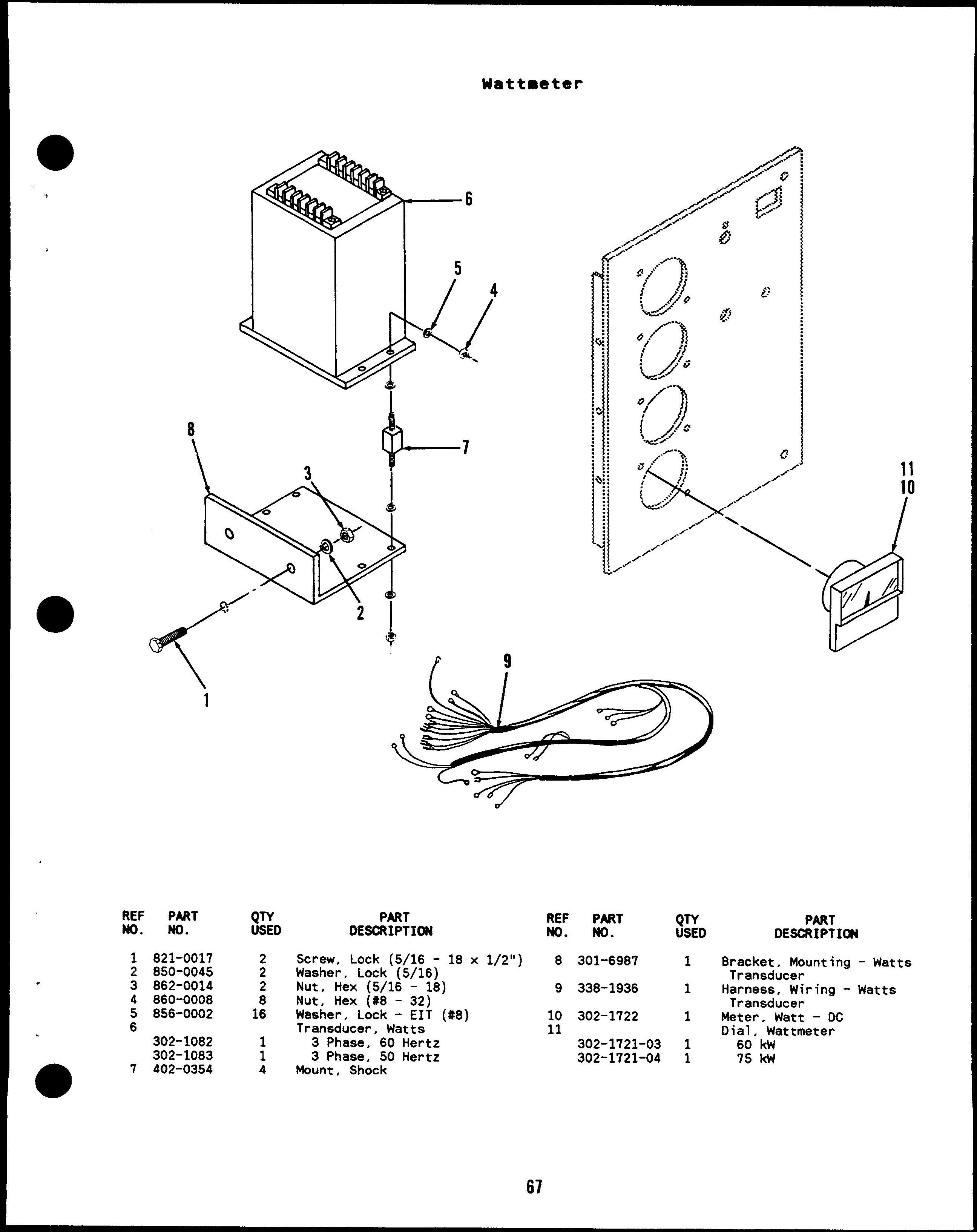
Bracket, Mounting - Watts Transducer
Harnesa, Wiring - Watts Transducer
Ueter, Watt - DC Dial, Wattmeter 60 kw
PART
No. 1 821-0010 2 234-0370
815-0350 4 301-3156 5 821-0010
6 234-0361 7 821-0018
8 856-0006 QTY USED 8 Ii 3 4 1 6 1
Screw, Self-Locking - Hex
Washer Hd (1/4 - 20 x 1/2”)
Grille, Air - Generator Inlet
Screw, Tap - Hex Washer Head (#lo - 32 X 3/8”)
Panel, Access
Screw, Self-Locking - Hex
Washer Hd (1/4 - 20 x 1/2”)
Wrappar, Sell - End
screw, Self-Locking - Hex
Washer Hd (1/4 - 20 x 5/8”)
Washer, Lock - EIT (1/4)
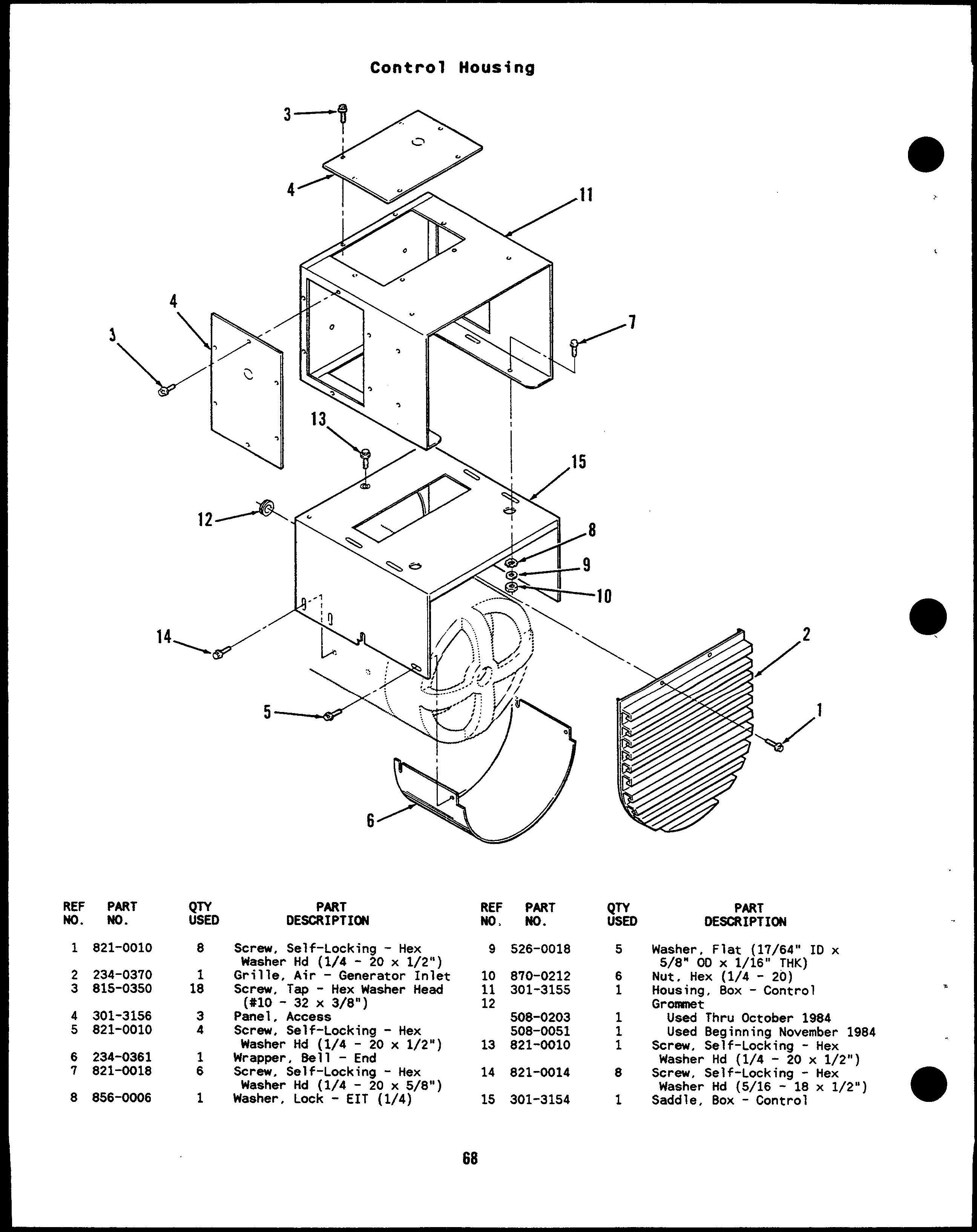
526-0018
870-0212 301-3155
508-0203 508-0051 821-0010
821-0014 301-3154
. .. .. DESCRIPTION
Waaher, Flat (17/64” ID x 5/8” OD X 1/16” THK)
Nut, Hex (1/4 - 20)
Housing, 80X - Control Grcxmnat
Used Thru October 1984
Used 8eginning November 1984
screw, Self-Locking - Hex Washer Hd (1/4 - 20 x 1/2”)
Screw, Self-Locking - Hex
Washer Hd (5/16 - 18 x 1/2”)
Saddle, 80X - Control
813-0096
301-9406
301-9259
301-9458
301-9403
301-9405
301-9255
301-9409
301-9408
301-9407
301-9256
301-9459
898-0863
898-0865
898-0875
898-0869 898-1112
898-0974
898-0976 800-0028
526-0022
850-0045
862-0015 f31~-o15(j
850-0040
850-0030
320-1061
320-1062
320-0344
320-1409
320-0359
320-1411
320-0420
320-0421
320-1408
320-1407
320-1404
320-0411
320-0379
320-0418
320-0412
320-0380 320-1405
320-1049
320-0446
320-0346
320-0425
320-0347
320-0426
320-0348
320-0447
Screw, Machine - Round Head (#10 -32 X 1/4”)
Cover, Top Cover, Breaker - Circuit ‘“ x 3-1/4” 8reaker Hole a 3-1/4” x 1-1/2” 8reaker Hole Panel, Front Wrapper, Enclosure Cover, Access - Side Panel, Access - Bottom Panel, End Panel, End Bracket, Mounting - Circuit Breaker
Used on Circuit Breakers
480 Volts and Up
Used on Circuit Breakers
240 Volts and Below
Sleeving, Shrinkable
0.75” ID
1.00” ID
1.50” ID
2.00” ID
3.00” ID
Sleeving, Fiberglass
0.75” IO
1.00” ID
Screw, Cap - Hex Head (5/1618 X l“)
Washer, Flat (21/64” ID x 9/16” 00 X 1/16” THK)
Washer, Lock - Spring (5/16)
Nut, Hex (5/16 - 18)
Screw, Machine - Round Head (1/4 - 20 x 1-1/2”)
Washer, Lock - Spring (1/4)
Washer, Lock (#10)
Breaker, Circuit
Two pole
125 Amp, 240 VAC
150 Amp, 240 VAC
175 Amp, 240 VAC
200 Amp, 240 VAC
225 Amp, 240 VAC
250 Amp, 240 VAC
300 Amp, 240 VAC
350 Amp, 240 VAC
Three Pole
80 AmP, 240 VAC
80 Amp, 480 VAC
80 Amp, 600 VAC
90 AmP, 240 VAC
90 Amp, 480 VAC
90 Amp, 600 VAC
100 Amp, 240 VAC
100 Amp, 480 VAC
100 Amp, 600 VAC
125 hp. 240 VAC
125 Amp, 480/600 VAC
150 hp, 240 VAC
150 Amp, 480/600 VAC
175 Amp, 240 VAC
175 Am, 480/600 VAC
200 Amp. 240 VAC
200 Amp, 480/600 VAC
REF PART NO. NO.
320-0349
320-0269
320-0422
320-0445
320-0423
320-0401
320-0448
320-1231 320-1421
320-1428 320-0738
320-0700
320-0988 320-1222
320-0975
320-0620
320-0300
320-1425
320-0556
320-0658
320-0453
320-0392
320-0370
320-1427
320-1432
320-1430
320-0688
320-0731
320-0529
320-1433
320-0438
320-0627
320-0524
320-0238
320-0315
320-0215
320-0573
320-0285
320-0708 320-0268 320-0275
320-0331 320-0279
320-1144 320-1424
320-1300
320-0772
320-1422
320-1145
320-1035
320-1429
PART DESCRIPTION
225 Amp, 240 VAC
225 Amp, 480/600 VAC
250 Amp, 240 VAC
250 Amp, 480/600 VAC
300 Amp, 240 VAC
300 Amp, 480/600
350 Amp, 240 VAC
Three Pole with Aux Contact
90 Amp, 480 VAC
100 Amp, 480 VAC
125 Amp, 600 VAC
150 Amp, 480/600 VAC
175 Amp, 240 VAC
200 Amp, 480/600 VAC
225 Amp, 240 VAC
250 Amp, 480/600 VAC
300 Amp, 240 VAC
300 Amp, 480/600 VAC
350 Amp, 240 VAC
Three Pole with 12 Volt
Shunt Trip
125 AJllp, 600 VAC
150 Amp, 600 VAC
175 Amp, 600 VAC
200 Amp: 600 VAC
300 Amp, 600 VAC
Three Pole with 24 Volt Shunt Trip
100 Amp, 480 VAC
100 Amp, 600 VAC
125 Amp, 600 VAC
150 Amp, 600 VAC
175 Amp, 600 VAC
200 Amp, 600 VAC
225 Amp, 600 VAC
300 Amp, 600 VAC
350 Amo, 240 VAC
350 Amp, 600 VAC
Three Pole with 120 Volt
Shunt Trip
125 Amp, 600 VAC
150 Am~, 600 VAC
175 Amp, 600 VAC
200 Amp. 600 VAC
225 Amp, 600 VAC
250 Amp, 600 VAC
300 Amp, 600 VAC
350 Amp, 600 VAC
Three Pole with 480 Volt
Shunt Trip
300 Amp, 600 VAC
350 Amp. 600 VAC
Two Pole with 12 or 24 Volt
Shunt Tri~ and Aux Contact
200 Amp, 240VAC (24 V)
300 Amp, 240 VAC (24 V)
Three Pole with 12 or 24 Volt Shunt Trip and Aux
Contacts
90 Amp, 480 VAC (12 V)
150 tip, 240VAC (12 V)
150 Amp, 600 VAC (24 V)
200 Amp, 24o VAC (24 V)
22S Amp, 240 VAC (12 V)
250 Amp, 600 VAC (24 V)
815-0350
301-9720
301-9721
301-9403
301-9405
301-9255
301-9409
301-940B
301-9407
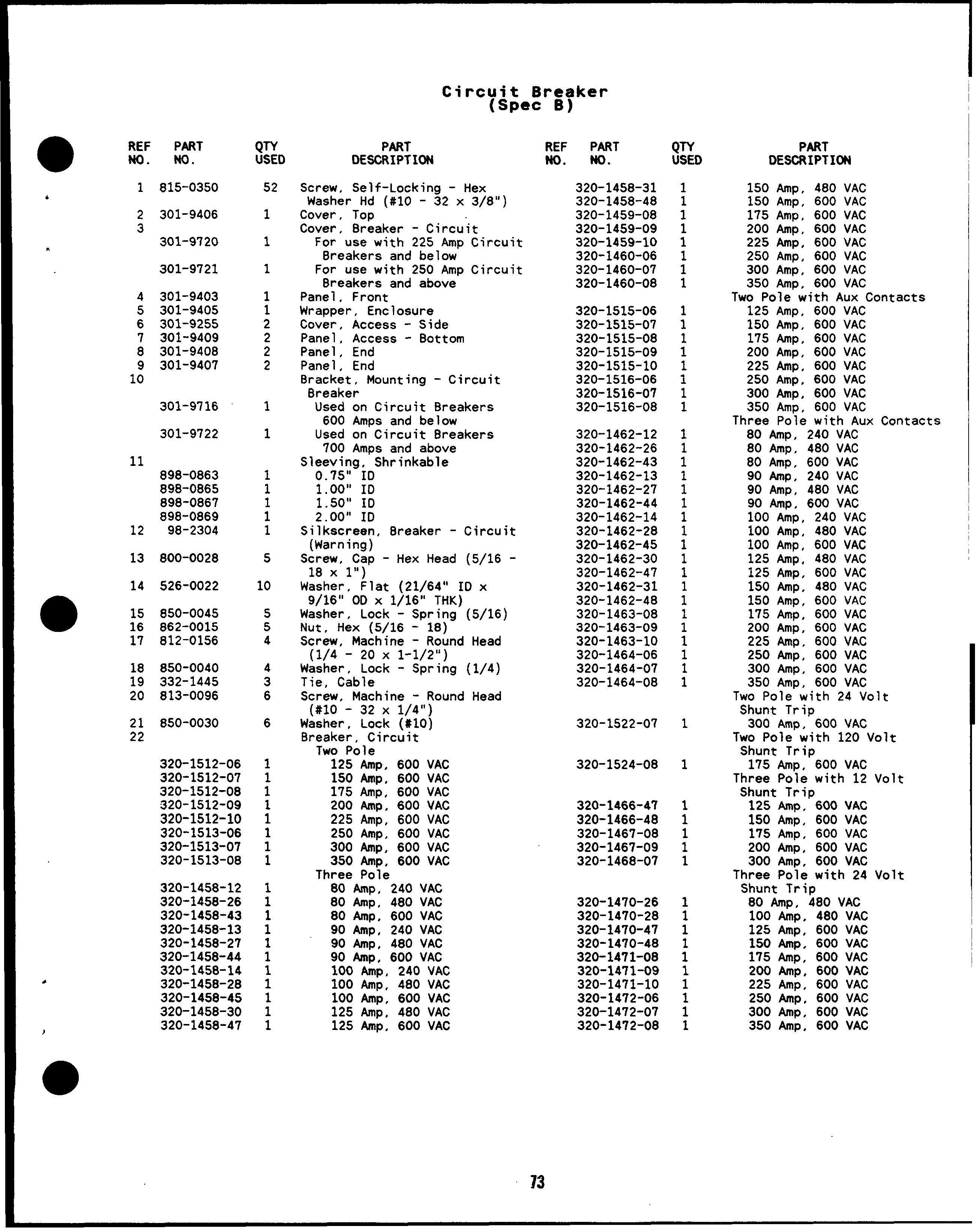
Screw, Self-Locking - Hex Washer Hd (#10 - 32 x 3/8”)
Cover, Top Cover, Breaker - Circuit
For use with 225 Amp Circuit Breakers and below
For use with 250 Amp Circuit Breakers and above Panel, Front Wrapper, Enclosure Cover, Access - Side Panel, Access - Bottom Panel, End Panel, End Bracket, Mounting - Circuit Breaker
Used on Circuit Breakers
600 Amps and below
Used on Circuit Breakers
Amps and above Sleeving, Shrinkable
9/16’’”OD X-1)16;’ THK Washer, Lock - Spring Nut, Hex (5/16 - 18) 850-0045 862-0015 812-0156
850-0040 332-1445 813-0096
320-1512-06
320-1512-07
320-1512-08
320-1512-09
320-1512-10
320-1513-06
320-1513-07 320-1513-08
320-1458-12
320-1458-26
320-1458-43
320-145B-13
320-1458-27
320-1458-44
320-1458-14
320-1458-28
320-1458-45
Screw, Mach”ine - Round Head (1/4 -20 x 1-1/2”) Washer, Lock - Spring (1/4) Tie, Cable Screw, Machine - Round Head (#10 -32 X 1/4”) Washer, Lock (#10) Breaker, Circuit
Two Pole
125 Amp, 600 VAC
150 Amp, 600 VAC 175 Amp, 600 VAC 200 Al!lp, 600 VAC 225 Amp, 600 VAC
250 Amp, 600 VAC
300 Amp, 600 VAC
350 AMp, 600 VAC Three Pole
80 Amp, 240 VAC
80 Amp, 480 VAC
80 Amp, 600 VAC
90 Amp, 240 VAC
90 Amp, 480 VAC
90 Amp, 600 VAC
100 Amp, 240 VAC
100 Amp, 480 VAC
100 Amp, 600 VAC
125 Amp, 480 VAC
320-1458-31
320-1458-48
320-1459-08
320-1459-09 320-1459-10
320-1460-06
320-1460-07 320-1460-08
320-1515-06
320-1515-07
320-1515-08
320-1515-09
320-1515-10 320-1516-06 320-1516-07 320-1516-OB
320-1462-12 320-1462-26 320-1462-43 320-1462-13 320-1462-27 320-1462-44 320-1462-14
320-1462-28 320-1462-45 320-1462-30 320-1462-47 320-1462-31 320-1462-4B 320-1463-08 320-1463-09 320-1463-10 320-1464-06
320-1464-07
320-1464-OB
150 Amp, 480 VAC
150 Amp, 600 VAC
175 Amp, 600 VAC
200 Amp, 600 VAC
225 Amp, 600 VAC
250 Amp, 600 VAC
300 Amp, 600 VAC
350 Amp, 600 VAC
Two Pole with Aux Contacts
125 Amp, 600 VAC
150 Amp, 600 VAC
175 Amp, 600 VAC
200 Amp, 600 VAC
225 hp, 600 VAC
250 Amp, 600 VAC
300 Amp, 600 VAC
350 Amp, 600 VAC
Three Pole with Aux Contacts
80 Amp, 240 VAC
BO Amp, 480 VAC
80 Amp, 600 VAC
90 tip, 240 VAC
90 Amp, 4B0 VAC
90 Amp, 600 VAC
100 Amp, 240 VAC
100 Amp, 480 VAC
100 Amp, 600 VAC
125 hp. 480 VAC
125 Amp, 600 VAC
150 Amp, 480 VAC
150 Amp, 600 VAC
175 Amp, 600 VAC
200 Amp, 600 VAC
225 Amp, 600 VAC
250 Amp, 600 VAC
300 Amp, 600 VAC
350 Amp, 600 VAC
Two Pole with 24 Volt
Shunt Trip
300 Amp, 600 VAC
Two Pole with 120 Volt
Shunt Trip
175 Amp, 600 VAC
Three Pole with 12 Volt
Shunt Trip
320-1466-47
320-1470-26
320-1458-30 320-1458-47 320-1524-08
125 Anw, 600 VAC
125 Amp, 600 VAC
150 Amp, 600 VAC
175 Amp, 600 VAC
200 Amp, 600 VAC
300 Amp, 600 VAC
Three Pole with 24 Volt
Shunt Trip
80 Amp, 4B0 VAC
100 Amp, 480 VAC
125 Amp, 600 VAC
150 Amp, 600 VAC
175 Amp, 600 VAC
200 Amp, 600 VAC
225 Amp, 600 VAC
250 Amp, 600 VAC
300 Amp, 600 VAC
350 Amp, 600 VAC
320-1474-47 1
320-1474-48 1
320-1475-09 1
320-1475-10 1
320-1476-06 1
320-1476-07 1
320-1476-08 1
320-1484-07 1
320-1484-08 1
320-1536-09 1
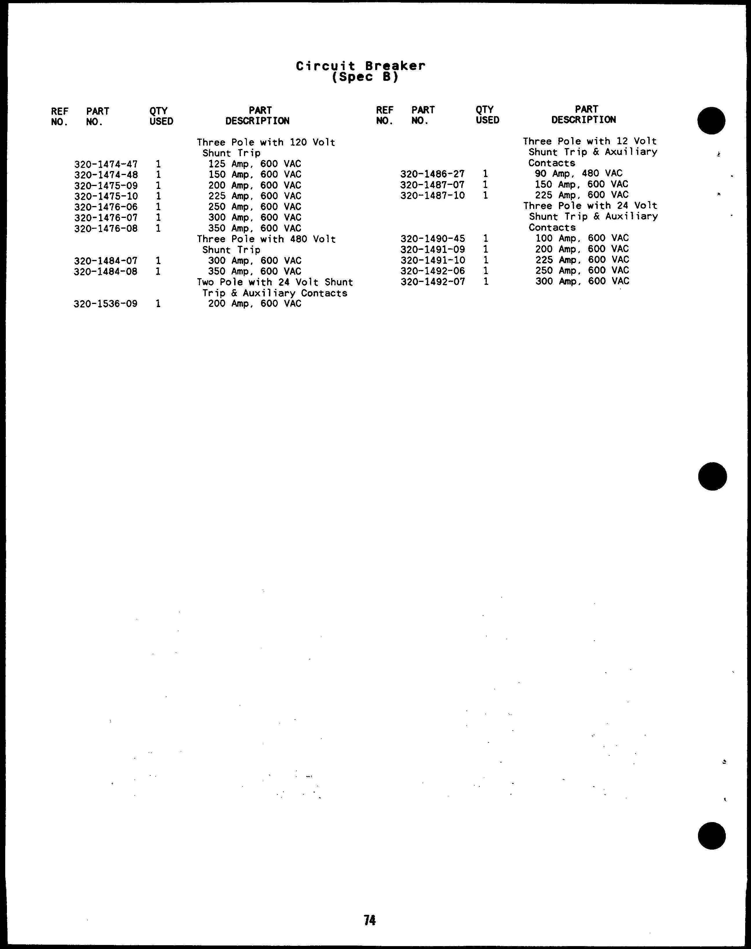
PART DESCRIPTION
Three Pole with 120 Volt
Shunt Trip
125 Amp, 600 VAC
150 Amp, 600 VAC
200 Amp, 600 VAC
225 Amp, 600 VAC
250 Amp, 600 VAC
300 Amp, 600 VAC
350 Amp, 600 VAC
Three Pole with 480 Volt
Shunt Trip
300 Amp, 600 VAC
350 Amp, 600 VAC
Two Poie with 24 Volt Shunt Trip & Auxiliary Contacts
200 Amp, 600 VAC
320-1486-27
320-1490-45
PART DESCRIPTION
Three Pole with 12 Volt Shunt Trip & Axuiliary & Contacts
90 Amp, 480 VAC
150 Amp, 600 VAC
225 Amp, 600 VAC
Three Pole with 24 Volt Shunt Trip & Auxiliary Contacts
100 Amp, 600 VAC
200 Amp, 600 VAC
225 Amp, 600 VAC
250 Amp, 600 VAC
300 Amp, 600 VAC
Engine Parts contact: Phone 269 673 1638 Email: engineparts2@gmail.com www.Diesel-Generator-Engine-Parts.com