6 minute read
Installation & Maintenance


INSTALLATION NOTES
Shafts must be parallel. Supporting structures must be of sufficient rigidity to maintain true alignment. Mount sprockets as close as possible to bearings.
Advertisement
Check correct alignment of each sprocket by use of a straight edge.
Roller chain can be used in practically any position provided the shafts are parallel. Where the slack strand is nearly vertical, or where torque variation causes waves or whip in the chain, an idler must be used to take up the excessive slack. The idler should preferably be near to the larger sprocket in the drive, located on the outside of the slack strand of the chain. Where layout makes this impossible it is permissible to locate the idler on the inside of the chain.
CHAIN TENSION
Chains should be fairly tight at installation with only a small amount of slack. With vertical drives the chain should be kept snug. After the first few weeks of operation, re-check chain tension and adjust if necessary.
FIXED CENTRE APPLICATIONS
An idler sprocket is generally recommended for fixed centre drives. It should be positioned on the slack side as close to the larger sprocket as feasible. The tensioning sprocket should have a minimum of three teeth engaged and be a minimum of four links away from the nearest sprocket.
Chain Tensioners
Normal Positioning
Reversible Drives
Chain Engagement
1 2 3
Vertical Positioning
Multi Sprocket Drives
LUBRICATION
Effective lubrication is essential in order to ensure optimum wear life from any chain. To be effective it must form a film of lubricant between the wearing parts, (the pin and bush), of the chain. It has therefore to be of suitable viscosity and be delivered to the gap between the sideplates such that it can penetrate into the space between the pin and bush. The viscosity, amount and type of lubricant is governed by the size of chain and the operating conditions involved. Oil will only penetrate into the bearing area of the chain when the chain is slack, therefore oil should be delivered to the slack strand just after the driver sprocket. High speed drives are especially critical. These generally require a continuous stream of lubricant applied across the full chain width in order to act as a coolant as well as lubricating the bearing area. Three basic lubrication methods are recommended for use with Fenner roller chain.
TYPE 1 Drip Feed (for linear chain speeds up to 1 m/sec.)
Oil drops directed between the side plate gaps with a drip feed lubricator. Brush applicators may also be used, provided they are positioned to ensure that the oil is correctly delivered to the gap between the side plates. Volume and frequency should be sufficient to prevent discolouration of the lubricant in the chain joints. Any discolouration of the lubricant or of the pin will indicate insufficient lubrication penetrating into the bearing area. Air movement, due to the motion of the drive, can disturb and mis-direct the oil drops, therefore, with due regard for safety, check the applicator while the drive is running.
TYPE 2 Oil Bath or Disc Lubricator (for linear chain speeds up to 6 m/sec.)
With oil bath lubrication the lower strand of chain runs through an oil sump. With the chain running, the oil level in the sump should immerse the chain at its lowest point. The oil level and condition of the oil should be checked periodically to ensure sufficient volume of oil is present and that it has not emulsified or become contaminated.
A disc or oil slinger may also be used. In which case the disc picks up oil from the sump and deposits it on the chain, usually through a trough. The chain operates above the oil level. The diameter of the disc should be sufficient to ensure a rim speed between 3 and 15 m/s.
TYPE 3 Pump and Sump (for high speed drives).
Oil is pumped from the sump by a circulating pump capable of delivering a constant stream of oil, evenly distributed across the full width of the chain. The oil should be supplied on the inside of the chain loop and at the lower strand, when chain speeds exceed 10 m/s.
Chain Lubrication
Link Plates Clearances for Lubricant
Bush Roller Pin
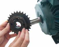
TO INSTALL
1. After ensuring that the mating tapered surfaces, bore and shaft, are completely clean and free from oil or dirt, insert the bush into the hub so that holes line up. 2. Sparingly oil thread and point of grub screws, or thread and under head of cap screws. Place screws loosely in holes threaded in hub, shown thus in diagram. 3. If a key is to be fitted, place it in the shaft keyway before fitting the bush. It is essential that it is a parallel key and side fitting only and has TOP CLEARANCE.
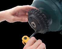
4. Clean shaft and fit hub to shaft as one unit and locate in position desired, remembering that bush will nip the shaft first and then hub will be slightly drawn on to the brush. 5. Using a hexagon wrench tighten screws gradually and alternately to torque shown in table below.
6. Hammer against large-end of bush, using a block or sleeve to prevent damage. (This will ensure that the bush is seated squarely in the bore.) Screws will now turn a little more. Repeat this alternate hammering and screw tightening once or twice to achieve maximum grip on the shaft. 7. After drive has been running under load for a short time stop and check tightness of screws. 8. Fill empty holes with grease to exclude dirt.
TO REMOVE
1. Slacken all screws by several turns, remove one or two according to number of removal holes shown thus • in diagram. Insert screws into removal holes after oiling thread and under head of cap screws. 2. Tighten screws alternately until bush is loosened in hub and assembly is free on the shaft.
3. Remove assembly from shaft.
INSERT BUSH

TIGHTEN SCREWS FINGER TIGHT

TIGHTEN SCREWS TO THE CORRECT TORQUE SETTING

INSERT SCREWS AND LOCATE ON SHAFT

TIGHTEN SCREWS ALTERNATELY
REMOVING A TAPER LOCK BUSH
REMOVAL HOLES •
Screw tightening torque (Nm) 5.6 5.6 20.0 20.0 20.0 30.0 50.0 90.0 90.0 115.0 115.0 170.0 170.0 190.0 190.0 270.0 270.0 Qty 2 2 2 2 2 2 2 2 2 2 3 3 3 3 3 3 3
Size (BSW) 1/4" 1/4" 3/8" 3/8" 3/8" 7/16" 1/2" 5/8" 5/8" 1/2" 1/2" 5/8" 5/8" 3/4" 3/4" 7/8" 7/8"
Screw
details Hex Socket size (mm) 3 3 5 5 5 6 6 8 8 10 10 12 12 14 14 14 14
Large end diameter (mm) 35.0 38.0 47.5 57.0 57.0 70.0 85.5 108.6 108.0 127.0 127.0 146.0 146.0 162.0 162.0 178.0 178.0
Bush Length (mm) 22.3 22.3 25.4 25.4 38.1 31.8 44.5 50.8 76.2 63.5 89.0 76.2 102.0 89.0 114.0 102.0 127.0
Approx mass (kg) 0.1 0.1 0.2 0.3 0.5 0.7 1.5 2.7 3.6 3.8 5.0 5.6 7.7 7.5 10.0 11.1 14.0


