2 minute read
The Variable Resistor


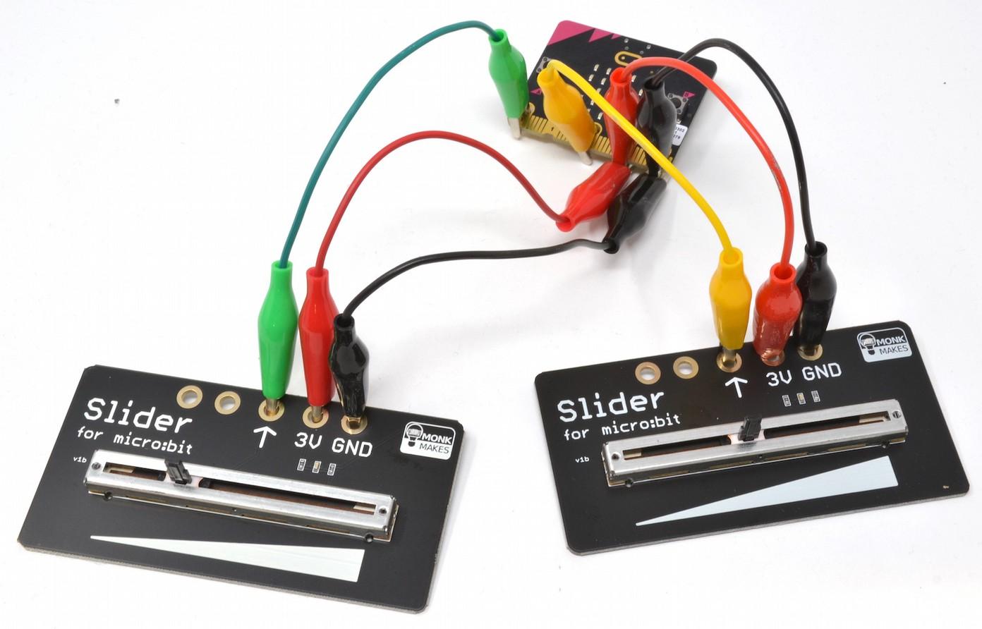
The main component of the Slider for micro:bit is a sliding variable resistor (also often called a potentiometer or just pot). The other components on the board are designed to protect your micro:bit against accidental damage should you connect things the wrong way around and the amber power LED that show that the Slider for micro:bit is powered. Here's the schematic diagram of a variable resistor and micro:bit working together.
The variable resistor is actually a resistive track, across which the micro:bit supplies a voltage of 0V at one end (the left) and 3V at the other (right). When you move the slider left and right you are moving a sliding electrical contact along the track. When the slider is at its leftmost position, the voltage at the slider will have a voltage of 0V and when its at the rightmost position the slider will have a voltage of 3V. When its in the middle position, this voltage will be half way between 0 and 3V in other words 1.5V. Note that the actual voltage will probably be less than 3V if you are powering the micro:bit from batteries. The slider voltage is measured by the micro:bit using P2 (or whichever pin you decide to use) as an analog input. The three connections 0, 1 and 2 can all be used as analog inputs. In Blockcode, you do this using the analog read pin block. This block measures the voltage at the connector specified but rather than return the actual voltage in Volts, it returns a number between 0 and 1023. When the slider is in its leftmost position, the reading will be 0 and when rightmost
Page 6
the reading will be 1023. Note that in practice the maximum value will be around 1013 rather than 1024 because of extra circuitry built into the Slider for micro:bit that protects the micro:bit. This example will display the reading when button A is pressed. Load it onto your micro:bit (see the link) and try moving the slider to various positions and then press button A and see what the reading is. Click on this link and then Download the program onto your micro:bit: https://makecode.microbit.org/_5x9RyqRKyTwL
If you are using Python, the following program does the same as the blocks code above. You can download all the Python example code for this kit at https://github.com/monkmakes/mb_slider. The program is called analog_reading.py. from microbit import *

while True: if button_a.was_pressed(): display.scroll(pin2.read_analog())
For more information on using MicroPython on your micro:bit, see the Section MicroPython with Mu, later in these instructions. Here are some more programs for you to test out the slider.
Page 7