8 minute read
A Brief History

Gearbox Lift Altar
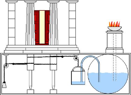
Chain
Pressure reservoir
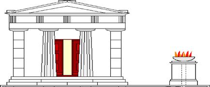
Over 2000 years ago the Greek engineer and inventor Ktesibios built the first machines powered by compressed air, for example, a catapult which used compressed air to hurl shot and spears. Heron of Alexandria built one of the best known compressed air Water reservoir
systems, which used the altar fire to generate compressed air to open the huge temple doors, as if by magic.
The heat from the altar fire heated the air in a pressure reservoir half filled with water. When the air was heated, it expanded, increasing the air pressure. The expanding air required more space, thus pressing the water out of the pressure reservoir into a water tank. As the weight increased the water tank moved downward, opening the doors.
Since the beginning of the 20th century pneumatic systems have been used to drive and control machines in industrial applications. In the field of construction and agricultural machines pneumatic systems are used to drive hammers and drills. In conveying technology, pneumatic systems use vacuum and pressure for applications such as sucking grain into flour mills or conveying flour. Even in the field of music, pneumatics are used for applications such as organs. In a pianola, a player piano, the keys are controlled pneumatically. You can observe pneumatic systems in action in the automotive industry, the textile and foodstuffs industry, electrical engineering, and even in space technology and many other areas encountered every day.
Pneumatic Systems and Components
Any pneumatic system consists of five subsystems for ▯ Generating compressed air ▯ Storing compressed air ▯ Conditioning and filtering compressed air ▯ Distributing compressed air ▯ Generating and controlling motion
Generating Compressed Air
Compressed air can be generated with a compressor or air pump and stored in compressed air bottles or other pressure containers.
Pump cylinder as compressor The pump cylinder included in the construction set allows you to generate the compressed air required for the compressed air reservoir. In industrial applications this is called the compressed air source. Function of pump cylinder: The pump cylinder consists of a pneumatic cylinder and an attached nonreturn shuttle valve. The nonreturn shuttle valve allows the pneumatic cylinder to be used as a compressed air pump.
Non-return shuttle valve (also called check valve): The nonreturn shuttle valve is simply connected to connection A on the pneumatic cylinder. The hose can be connected to the nonreturn shuttle valve. If the piston rod is pulled out of the cylinder, the nonreturn shuttle valve allows air to be sucked in from outside the cylinder. Pushing the piston rod back in pumps the air through the second opening in the nonreturn valve into the hose, while sealing off the first connection. We now have a pump cylinder similar to that used for a bicycle.
Storing Compressed Air
The pump cylinder pumps air into the compressed air reservoir. Similar to blowing up a balloon, the pressure increases on the inside. However the compressed air reservoir is very stable, preventing it from deforming under the pressure of the air. The nonreturn shuttle valve prevents the compressed air from escaping from the compressed air reservoir and flowing back to the pump cylinder. If a connected valve is now opened, the pressure forces the air to flow into the connected cylinder. This is also similar to an inflated balloon when opened slightly to let the pressure force air out of the balloon.
Conditioning and Filtering Compressed Air
To ensure that the pneumatic components operate correctly in industrial applications, it is important to condition the compressed air properly. For this purpose it is necessary to filter, cool, dehumidify and add oil to the air. However with the models in your Pneumatic Power Construction Set this is not required.
Distributing Compressed Air
The compressed air can be transported to the location required with the blue hoses. You can lay the air lines from the compressed air reservoir to the valves and cylinders.
Generating and Controlling Motion
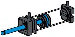
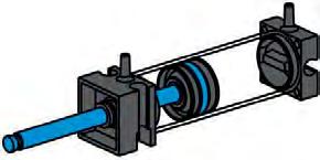
Pneumatic cylinder: We use pneumatic cylinders to generate motion with air. As a matter of principle we differentiate between "single acting" and "double acting" cylinders. Your Pneumatic Power Construction Set contains three different sizes of pneumatic cylinders with the same "double acting" function. The blue piston rod is movable and seals the cylinder. If you blow air into the cylinder through one of the two hose connections, the piston rod moves. If air is blown into it from the opposite side, the piston moves back in the other direction. The piston therefore has an active function in both directions of motion.
The connection which causes the piston rod to extend is designated connection A, and the connection for retracting the piston rod is called connection B. Since the piston rod in the cylinder can be extended as well as retracted by the air, we call the cylinder a "double acting" cylinder. You can perform an experiment to examine this in practical application.
Experiment:
Fasten a piece of the blue hose to connection A on a cylinder and connect it to the hose connection on the pump cylinder. When you actuate the pump cylinder, generating compressed air, the piston rod extends. Since the cylinder is double acting, the piston moves back when you connect the hose to connection B and blow in compressed air with the pump cylinder.
Connect hose, actuate pump cylinder
B A
Connect hose, actuate pump cylinder
B A
As already mentioned, however, there are also "single acting" cylinders. With such cylinders the piston rod moves in one direction only. A spring is frequently used to move it back in the other direction.
Pressure gage You can perform another experiment to show that air can be compressed.
Experiment:
Now extend the piston in the cylinder again by connecting your blue hose leading to the pump cylinder to connection A and blowing in compressed air. After the piston has extended, change to hose connection B and plug hose connection A by holding it closed with your finger.
B
Connect hose, actuate pump cylinder Hold shut
A
Connect hose, actuate pump cylinder
A
B
Observation:
The piston can only be pressed in a short distance. Do you know why?
Explanation:
Since you held air connection A closed with your finger, it was not possible for the air to escape. However air can be pressed together. For this reason it was possible to push the piston rod back slightly. The more the air is pressed together, the greater the air pressure in the cylinder. The pressure can be measured with a pressure gage. The unit for pressure is "bars" or "Pascals". The pressure can also be calculated. The equation for calculating the pressure is:
Pressure = force/area or abbreviated p = F/A
This equation shows that the pressure depends on the amount of force exerted on the round surface in the cylinder. As you recognized in your experiment, it is rather cumbersome to reconnect the hoses repeatedly. This work can also be accomplished by valves, as explained in detail in the next chapter.
Valves:
In pneumatics, the purpose of the valve is to control the flow of air to the pneumatic cylinder so that the cylinder is extended or retracted. A valve can be actuated mechanically, electrically, pneumatically or manually.
Your Pneumatic PROFI Pneumatic Power Construction Set contains manual valves. Each of these valves has four connections:
A P B
R
The middle connection P is for the compressed air coming from the compressed air reservoir. The left or right fitting (A or B) guides the compressed air to connection A or connection B on the cylinder. The connection marked R on the bottom of the valve serves to release the air or "relieve" the air pressure. This allows the air returning from the cylinder to escape. Perform the following experiment to see how the valve works.
Experiment:
Connect the compressed air reservoir to one of your valves. You can use the function model as described in the assembly instructions. For this purpose take a piece of the blue hose and fasten it to the hose connection on the compressed air reservoir and to connection P on the valve. Leave the other connections free. Set the blue switch on the manual valve to the center position and switch on the compressed air from the compressed air reservoir. First it is necessary to fill the compressed air reservoir with the pump cylinder.
Observation:
Nothing happens at all.
Explanation:
When the switch on the manual valve is set to the center position, the connections are closed and the air cannot flow in any direction.
Experiment:
Then turn the switch on the valve to the right (clockwise) and switch on the compressed air to the compressed air reservoir again. While doing this tap against the free fittings A and B repeatedly with your finger. Do the same after turning the valve switch to the left (counterclockwise). Don't forget to continue to fill the compressed air reservoir with compressed air by actuating the pump cylinder.
Observation:
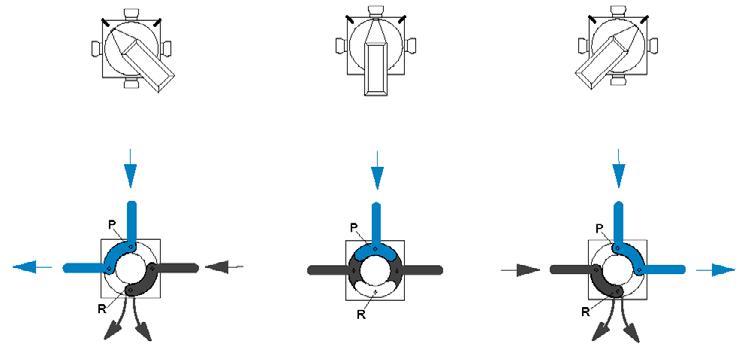
The air always flows through connection A when you turn the blue switch on the valve to the right (clockwise) and through connection B when you turn it to the left (counterclockwise).
Explanation:
This illustration helps you to understand how the air flows through the valve when you turn the switch in the various directions. Here the blue dash indicates compressed air flowing through the valve. The dark lines show how the air flows as it returns from the cylinder.
Left Center Right
P
B
R A B P
R A P
B
R A
The valve has four connections and three switch positions (center left right). For this reason the valve is called a 4/3way valve in pneumatic jargon.