
Owners Manual
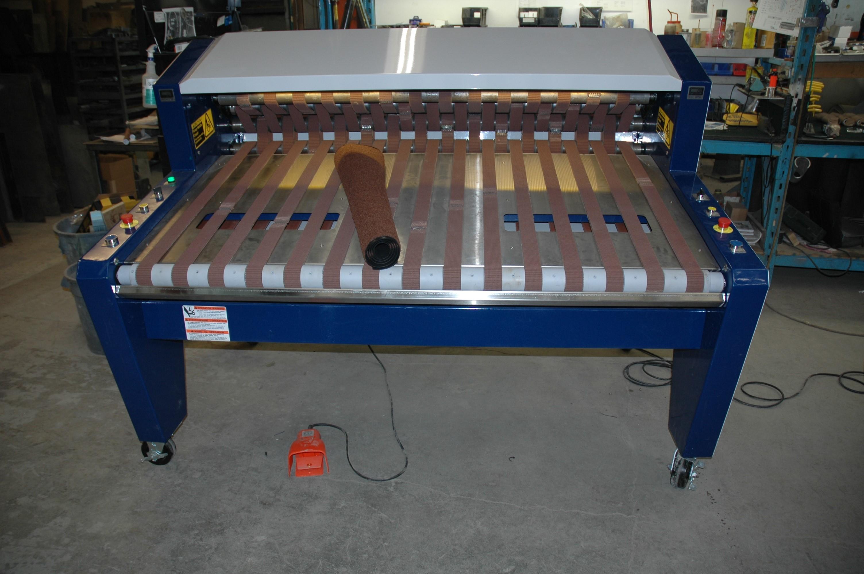
Rapid Roller

1. Preface
This manual has been prepared for the owner and operators of a CDF Systems Rapid Roller. Its purpose, aside from machine operation, is to promote safety through the use of accepted correct operating and maintenance procedures. Completely read the entire safety section before operating or servicing the machine. To obtain maximum life and efficiency from your Rapid Roller, and to aid in using the machine safely, read this manual thoroughly and follow instructions carefully.
2. Warranty
This Limited Warranty applies to physical goods, and only for physical goods, purchased from CDF Systems (the “Physical Goods”).
What does this limited warranty cover?
This Limited Warranty covers any defects in material or workmanship under normal use during the Warranty Period with the exception of wearing parts. These include, belts and belting, bearings and roller chain.
During the Warranty Period, CDF Systems will repair or replace, at no charge, products or parts of a product that proves defective because of improper material or workmanship, under normal use and maintenance.
This Limited Warranty is transferable.
What will we do to correct problems?
CDF Systems will either replace the Product at no charge, using new or refurbished replacement parts.
How long does the warranty period last?
The Warranty Period for Physical Goods purchased from CDF Systems is 1 Year from the date of purchase.
A replacement Physical Good or part assumes the remaining warranty of the original Physical Good or 1 Year from the date of replacement or repair, whichever is longer.
What does this limited warranty not cover?
This Limited Warranty does not cover any problem that is caused by:
conditions, malfunctions or damage not resulting from defects in material or workmanship
conditions, malfunctions or damage resulting from negligence, improper maintenance or modification
damaged or destroyed by natural causes including but not limited to lightning, flood, or other natural disaster
theft or loss of the Physical Goods
This Limited Warranty does not cover any shipping charges, handling charges, gift wrap fees or taxes. You are responsible for and must prepay all shipping charges.
You shall assume all risk of loss or damage to the Physical Good while in transit to CDF Systems.
This Limited Warranty is void if the Physical Goods are returned with removed, damaged or tampered labels or any alterations.
How do I obtain warranty service?
To obtain warranty service, you must obtain a Return Merchant Authorization (RMA) number and instructions on how to return a product by contacting us.
Deliver the Physical Goods, in either its original packaging or packaging providing an equal degree of protection, including any accessories or documents that were shipped with the Physical Goods to the address specified by CDF Systems.
To obtain the Return Merchant Authorization (RMA) number, you can contact us by any of the following contact methods:
In the United States, Mexico or Canada please call 1-800-986-6702 or visit: http://matpro-systems.com/contact/
3. Warranty Disclaimer
CDF SYSTEMS WARRANTIES TO THE PERIOD SPECIFIED ABOVE, FROM THE DATE THE PRODUCT WAS PURCHASED. EXCEPT AS STATED HEREIN, ANY IMPLIED WARRANTIES BY THE DISTRIBUTOR OR MERCHANTABILITY AND FITNESS ARE EXCLUDED. CDF SYSTEMS SHALL IN NO EVENT BE LIABLE FOR DEATH, INJURIES TO PERSONS OR PROPERTY, OR FOR INCIDENTAL, CONTINGENT, SPECIAL, OR CONSEQUENTIAL DAMAGES ARISING FROM THE USE OF OUR PRODUCTS.
4. Inspection Guarantee
You have just purchased a quality mat rolling machine from CDF Systems. This machine has been tested at various stages of its assembly to ensure your trouble free operation.
For your convenience, we have enclosed a parts list and diagrams detailing the components of the machine. If you have any questions, or should your machine require parts or service please call CDF Systems.
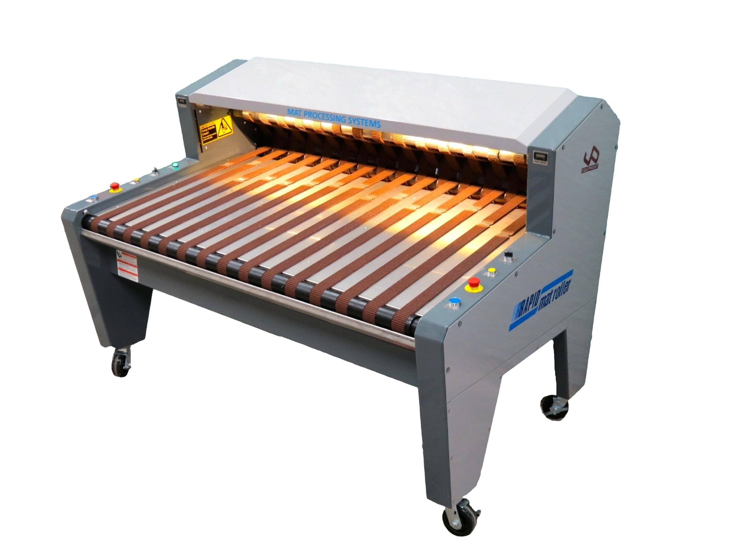
5. Introduction:
Congratulations on your purchase of the Rapid Roller mat rolling machine. Refer to this Operating Instructions Manual for all aspects regarding the safe and efficient use of your Rapid Roller mat rolling machine.
The Table of Contents on Page 1 will help you navigate this manual . Please keep this manual for future reference. Please ensure that you and anyone else who is operating, maintaining or using this mat rolling machine has read and understood the Safety, Operation and Maintenance sections of the Operating Instructions Manual prior to use.
For assistance if items in this publication are not understood, please contact :
Service Department
CDF Systems
Unit 6, 20113 92a Ave
Langley BC, Canada
V1M-3A5
1-800-986-6702
6. Safety
6.1 General Safety
1. Read and understand the entire owners manual before attempting assembly or operation
2. Read and understand the warnings posted on the machine and in this manual. Failure to comply with all of these warnings may cause serious injury.
3. Safety signs on this machine are placed to inform operators on the hazards and to promote safe operation of the machine. Important: If Safety Signs have been damaged, removed, become illegible or parts replaced without Safety Signs, new signs must be applied. New Safety Signs are available from CDF Systems.
4. This mat roller is designed and intended for use by properly trained and experienced personnel only
5. If you are not familiar with the proper and safe operation of a mat roller, do not use until proper training and knowledge have been obtained
6. Do not use this mat roller for other than its intended use. If used for other purposes, CDF Systems disclaims any real or implied warranty and holds itself harmless from any injury that may result from that use
7. Always wear approved safety glasses/face shields while using this mat roller
8. Before operating this mat roller, remove neck tie, rings, watches and other jewelry, and roll sleeves up past the elbows or wear tight fitting sleeves. Remove all loose clothing that may come in contact with the conveyor and confine long hair.
9. Wear non-slip footwear or have operators area outfitted anti-skid floor mats
10. Do not wear loose fitting gloves
11. Do not operate this machine while tired or under the influence of drugs, alcohol or any medication
12. Make certain the main disconnect switch is in the OFF position before connecting the machine to the power supply
13. Make certain the machine is properly grounded
14. Make all machine adjustments or maintenance with the machine locked out as per the ECP lockout procedure located on Page 25
15. Keep safety guards and shields in place at all times when the machine is in use. If removed for maintenance purposes, use extreme caution and replace the guards immediately.
16. Make sure the mat roller wheel brakes are set before use
17. Check for damaged parts. Before further use of the machine, a guard or other part that is damaged must be carefully checked to determine that it will operate properly and perform its
intended function. Check for alignment of moving parts, binding of moving parts, breakage of parts, mounting and any other conditions that may affect its operation. A guard or other part that is damaged must be properly repaired or replaced.
18. Provide for adequate space surrounding work area and non-glare, overhead lighting
19. Keep the floor around the machine clean and free of scrap material, oil and grease
20. Keep visitors a safe distance from the work area. Keep children away
21. Never leave the machine unattended with the power switch on. Turn the power switch OFF if not in use
6.2 Safety Alert Symbol

This Safety Alert symbol means: Your Safety is Involved!
IMPORTANT: The Safety Alert symbol identifies important safety messages on the Equipment and in the Manual . When you see this symbol, refer to the Owners Manual . When you see this symbol, be alert to the possibility of personal injury or death. Follow the
6.3 Safety Signs - Signal Words
Familiarize yourself with the following safety notices used in this manual: This means that if precautions are not followed, it may result in minor injury and/or possible machine damage.
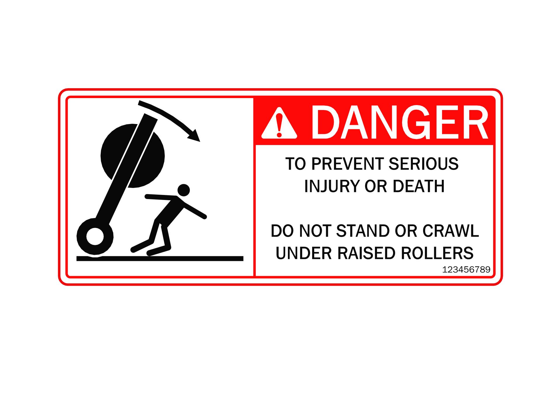
DANGER: (White letters on Red background) Indicates an imminently hazardous situation that, if not avoided, will result in death or serious injury. This word is to be limited to the most extreme situations, typically for machine components that, for functional purposes, cannot be guarded.
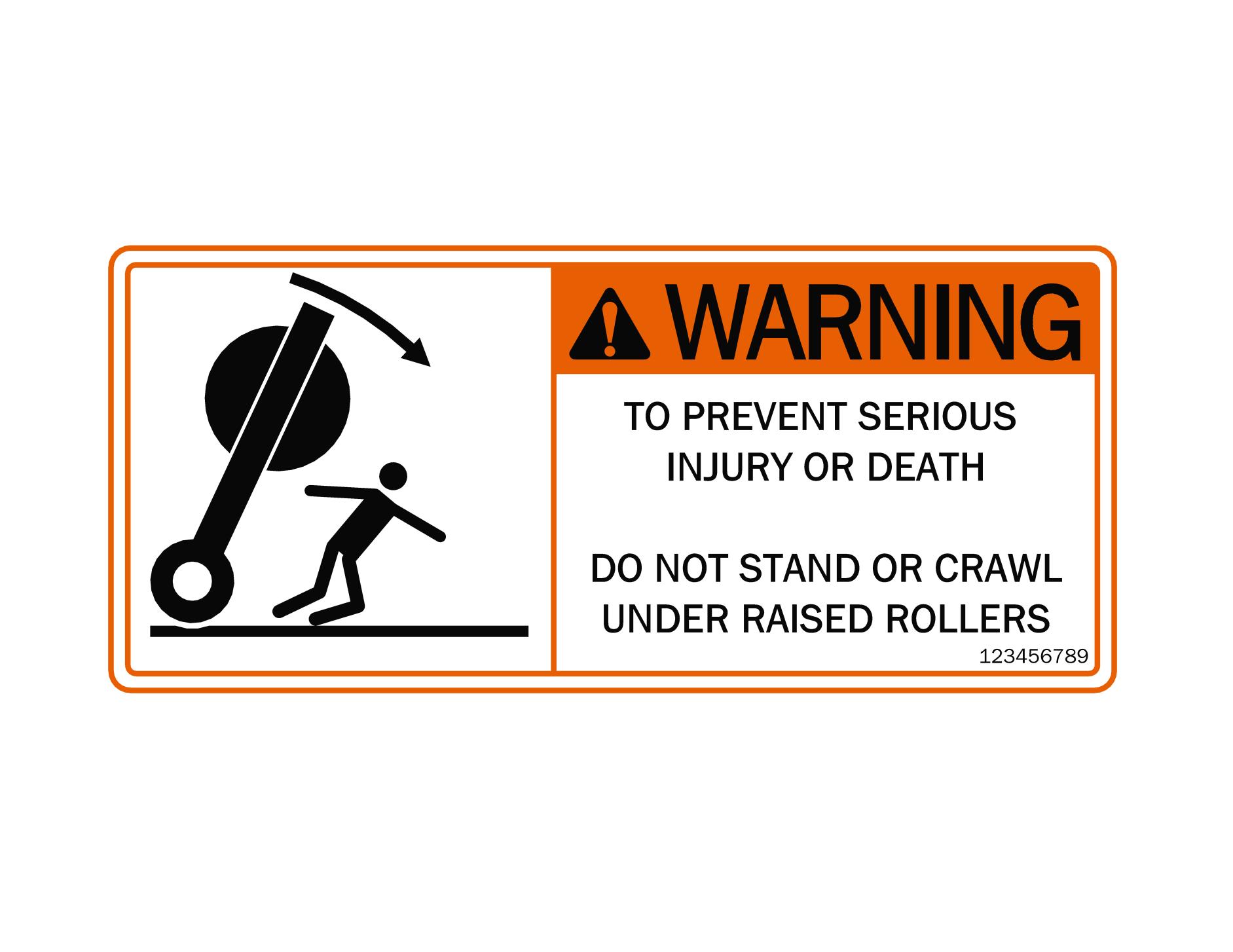
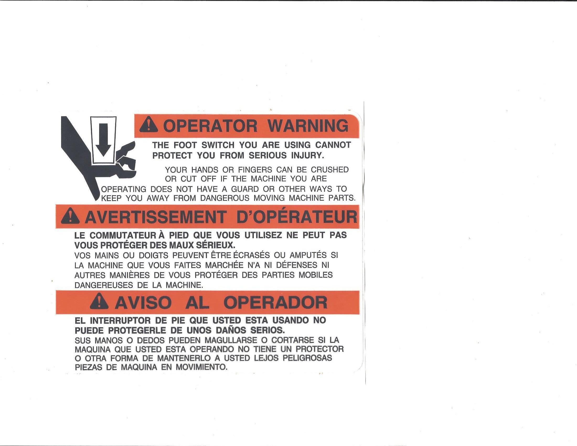
WARNING: (Black letters on Orange background) Indicates a potentially hazardous situation that, if not avoided, could result in death or serious injury, and includes hazards that are exposed when guards are removed. It may also be used to alert against unsafe practices.
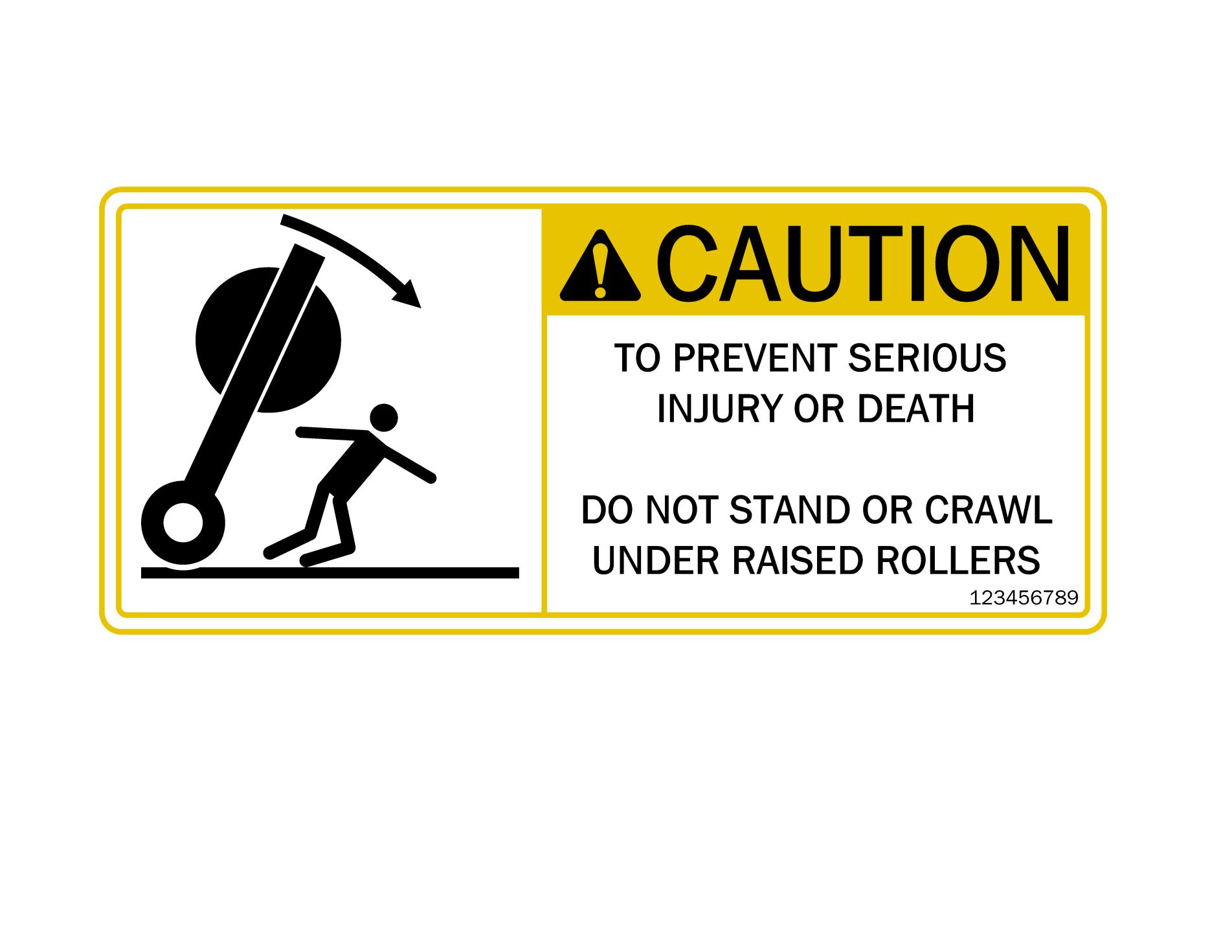
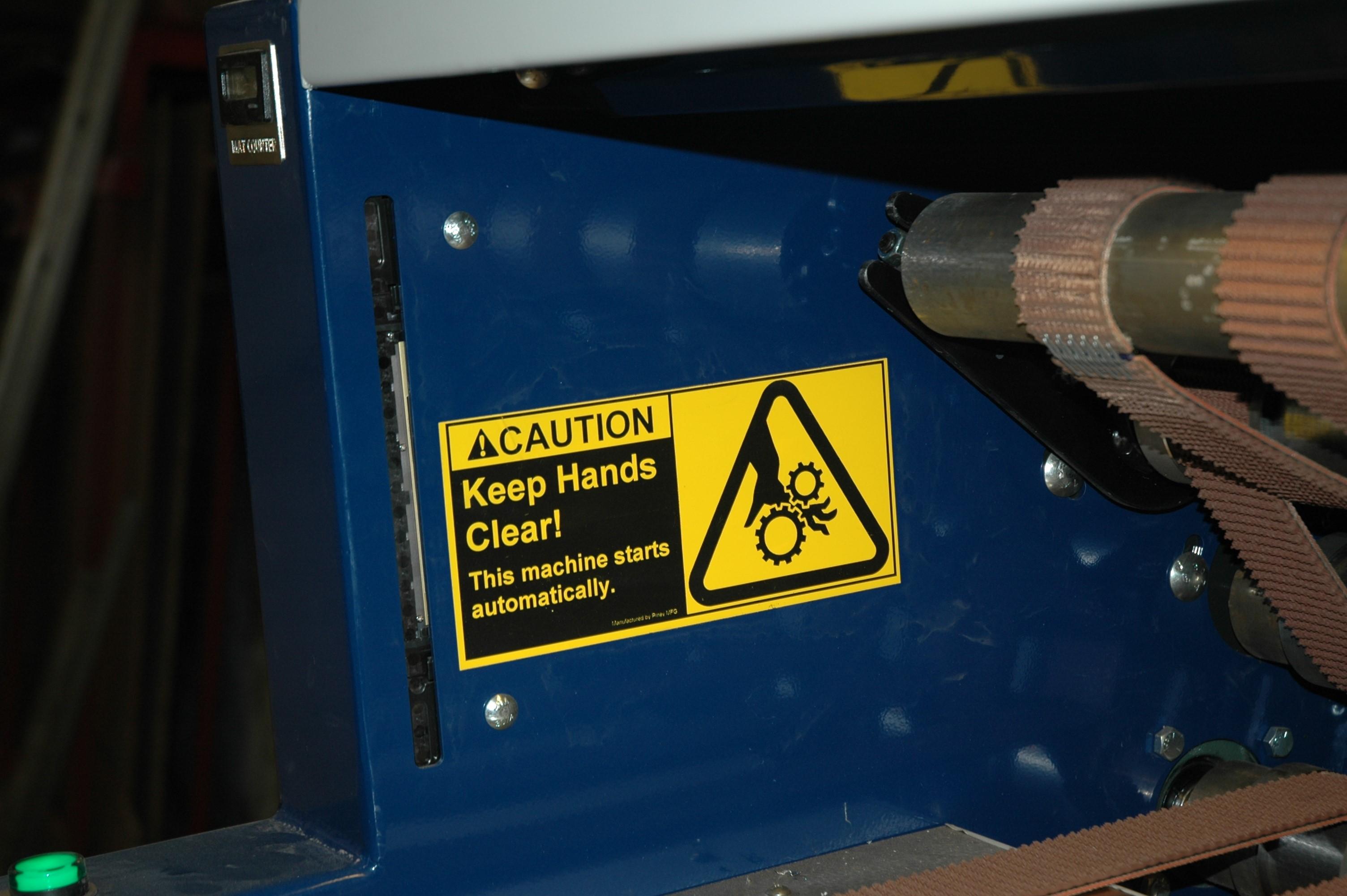
CAUTION: (Black letters on Yellow background) Indicates a potentially hazardous situation that, if not avoided, could result in minor or moderate injury. It may also be used to alert against unsafe practices.
6.4 Safety Signs - Locations and Decals
The types of Safety Signs and locations on the equipment are shown in the illustrations below. Good safety requires that you familiarize yourself with the various Safety Signs, the types of warning and the area, or particular function related to that area, that requires your SAFETY AWARENESS.
THINK SAFETY! WORK SAFELY!
REMEMBER: If Safety Signs have been damaged, removed, become illegible or parts replaced without Safety Signs, new signs must be applied. New Safety Signs are available from CDF Systems.
The types of Safety Signs and locations on the equipment are shown in the illustrations below. Good safety requires that you familiarize yourself with the various Safety Signs, the types of warning and the area, or particular function related to that area, that requires your SAFETY AWARENESS.
locations)
locations)
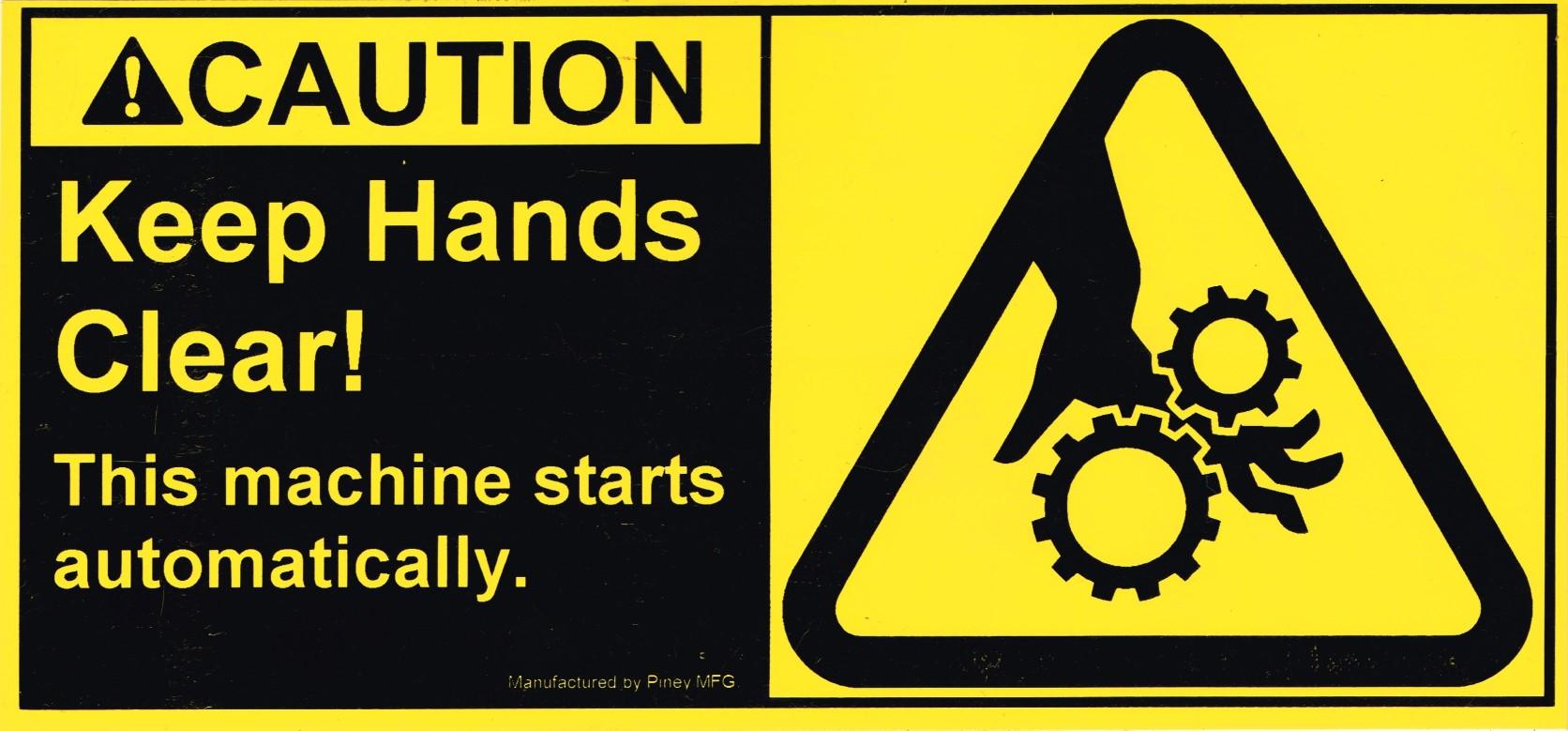
2. CAUTION (2
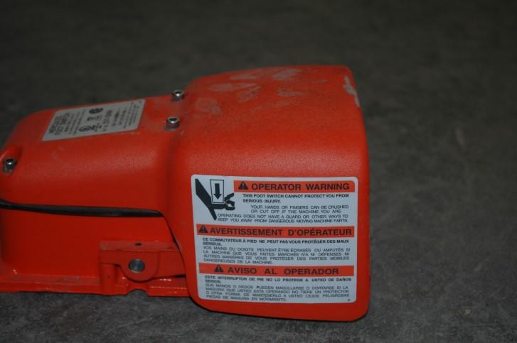
1. OPERATOR WARNING (2
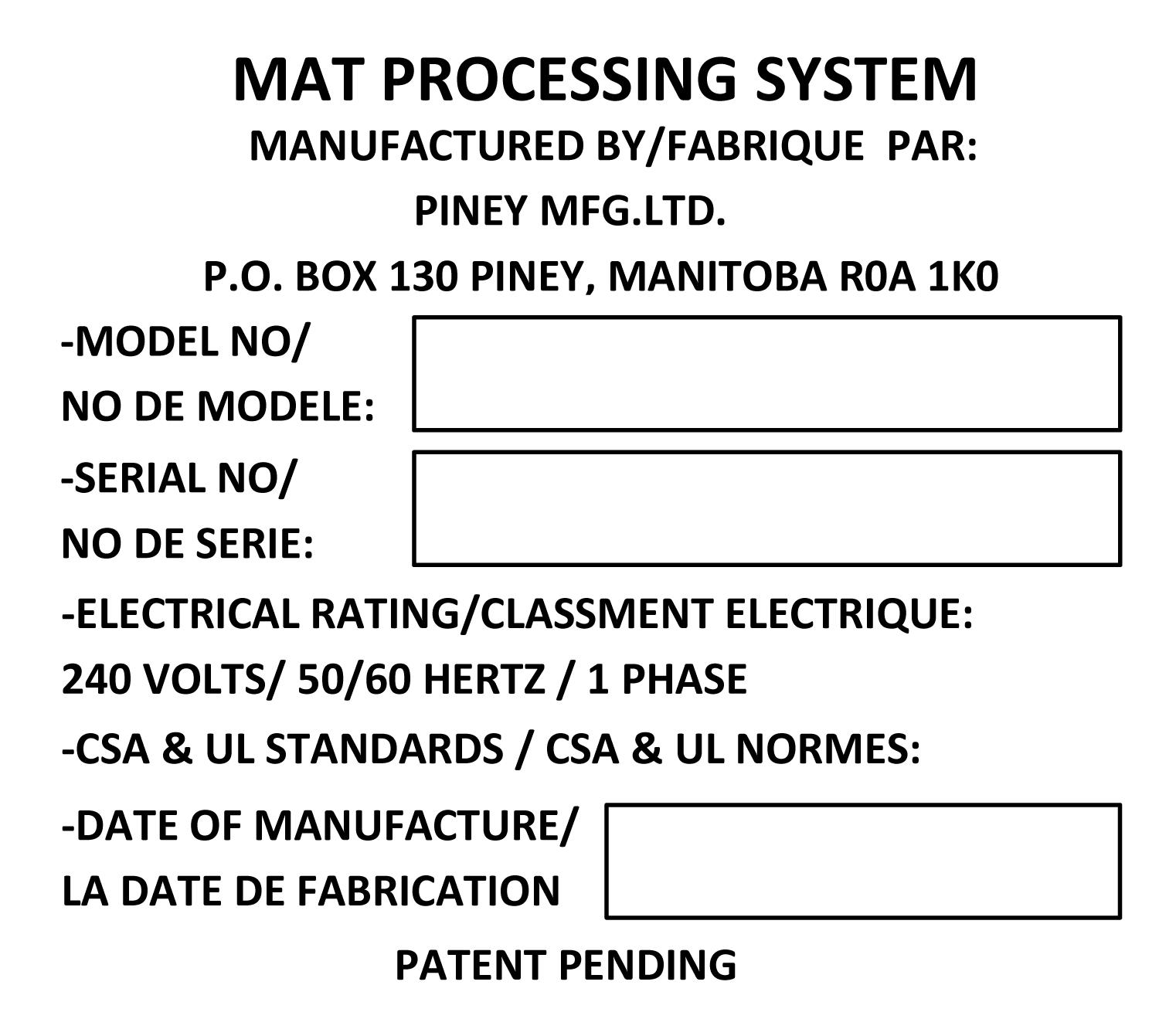
7. Model and Serial Number
Always provide the model and serial number of your Rapid Roller when ordering parts or requesting information and services.
For future reference, please record these here:
Model: Rapid Roller
Serial Number: ______________________
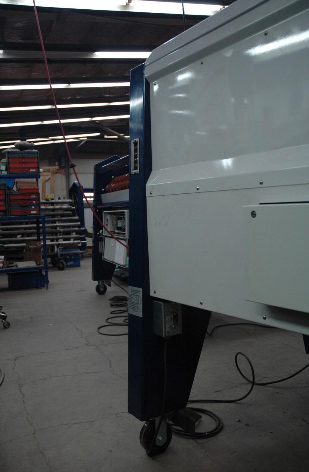
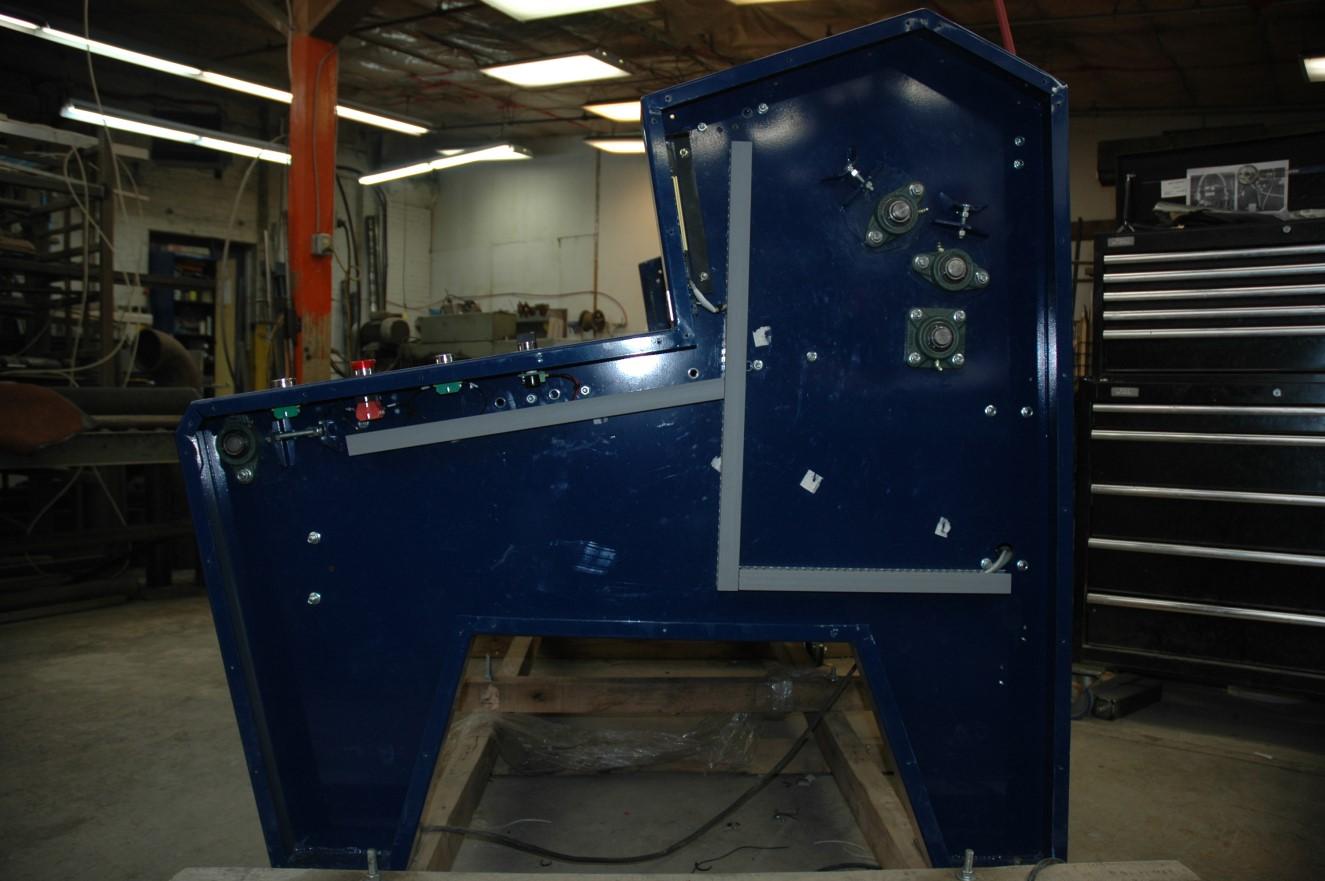
The serial number is printed on the tag located at the back of the machine as shown below.
8. Set Up
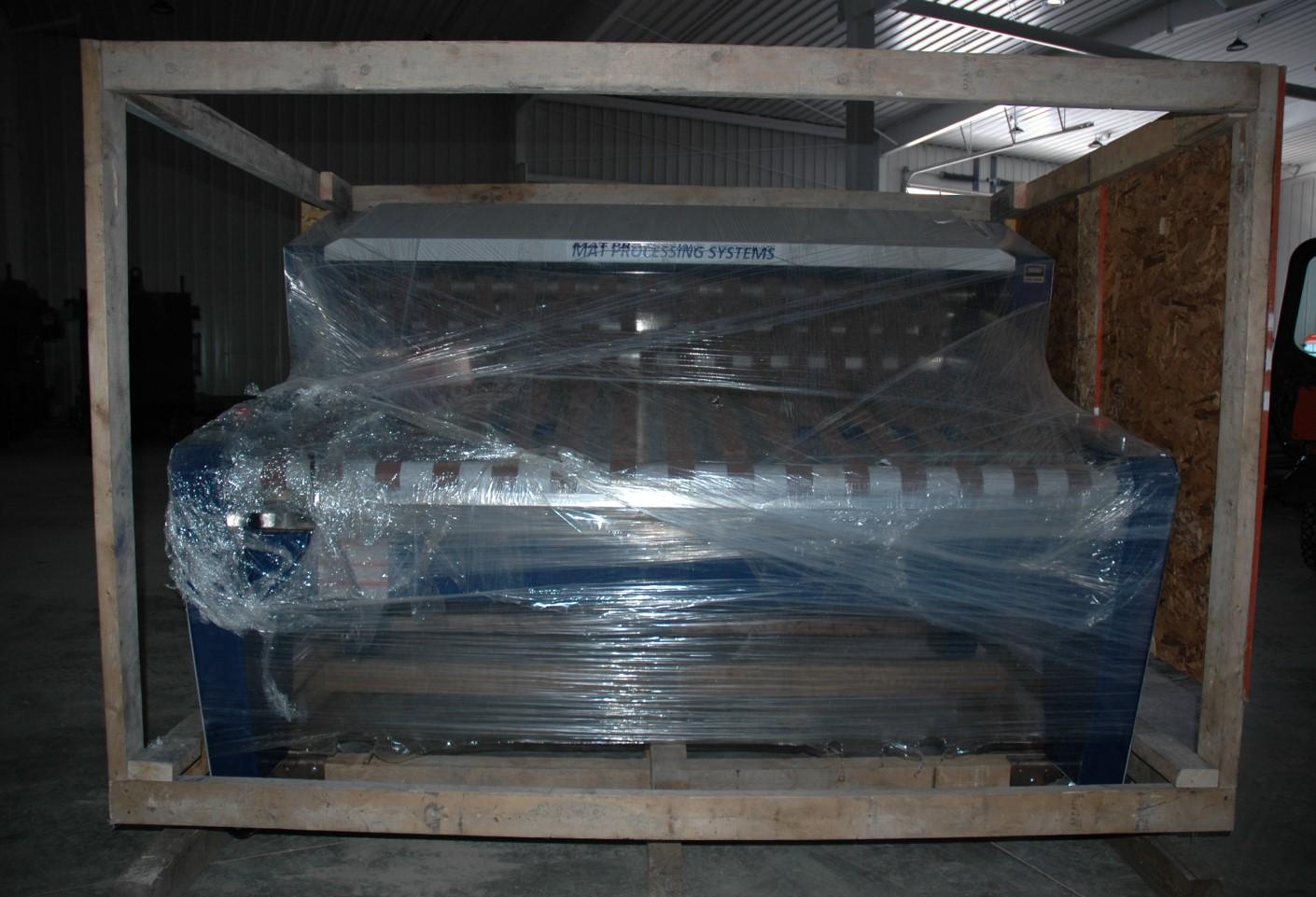
8.1 Removal from Shipping Crate
Damage may result
Caution: If lifting Rapid Roller with a forklift, care must be taken to place the forks under the timber support frame. Once the 6” x 6” timber support frame is removed, there is no safe way of lifting Rapid Roller with a fork lift. Do not lift machine by placing forks in direct contact to the chassis or components of the Rapid Roller.
Please use the following procedure to remove Rapid Roller from the shipping crate:
1) The shipping crate is comprised of two sections, a support frame constructed out of 6” x 6” timbers and wood framed sides. Carefully remove wooden sides and top from the 6” x 6” support frame. It is recommended to remove the hardware holding the crate together rather than using more destructive methods such as hammer and wrecking bar.
1) Remove shipping crate sides and framework
2) Remove 1/2” bolts
3) Remove 6” x 6” timbers
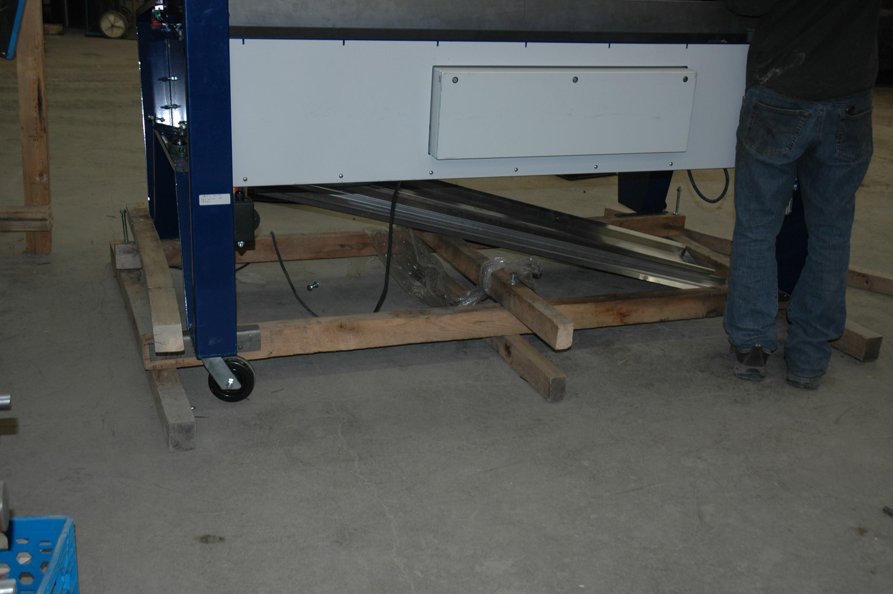
2) Locate and remove the 6 vertical bolts (1/2” diameter) holding the 6” x 6” timbers together, 6 places
3) Carefully lift the machine at each end frame (one at a time) with jacks and remove the upper and lower short 6” x 6” timbers, 3 places
4) Lower the machine to the floor until it is supported by the wheels on the four corners
5) remove lag screws
8.2 Pre-operation Setup
Damage or injury may
Caution: The Rapid Roller requires pre-operation setup. Electrical service connection to be performed by a qualified electrician in accordance to national and local electrical codes. Please follow the directions below:
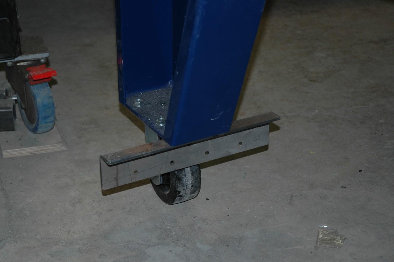
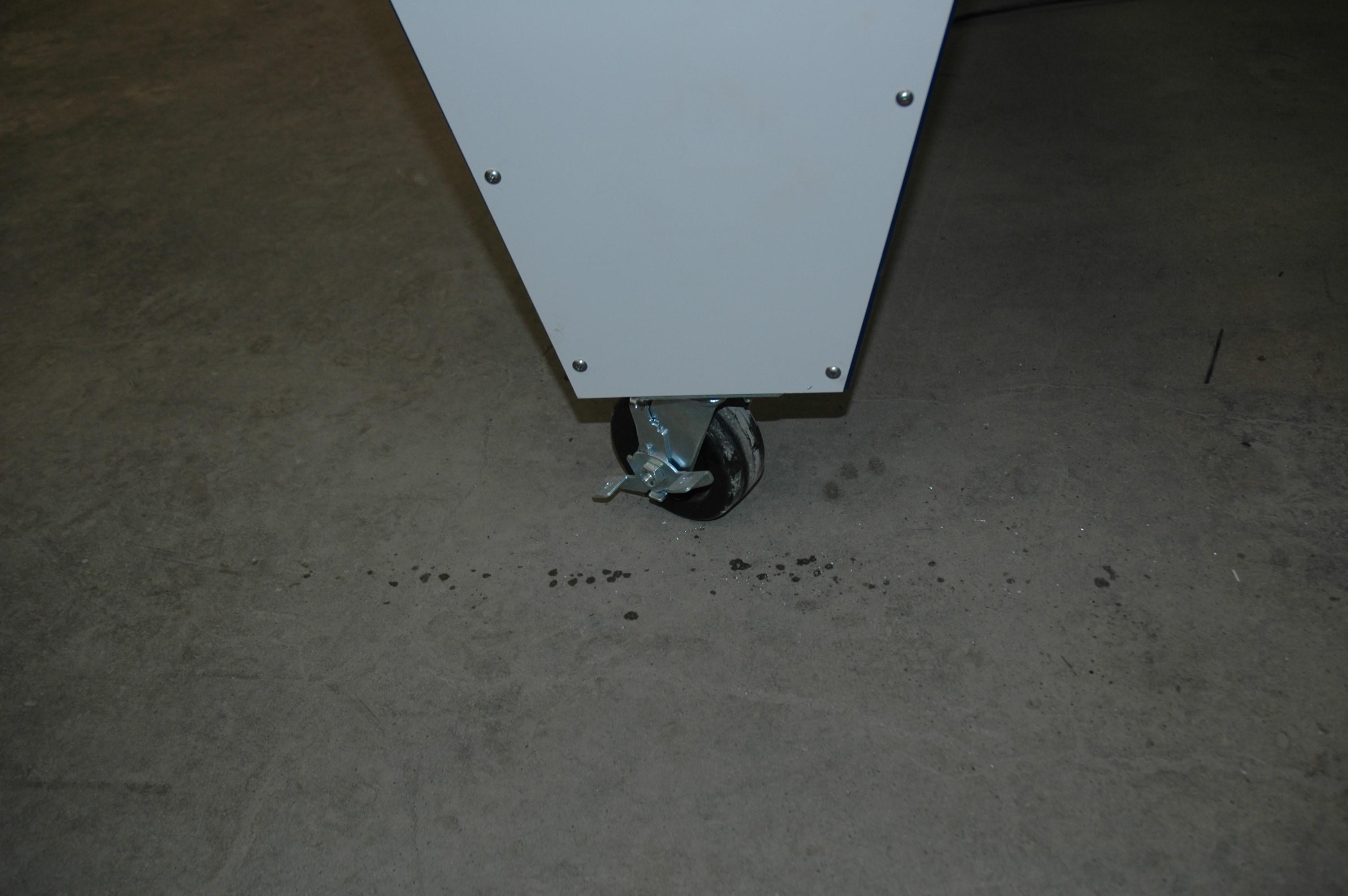
1) Choose a setup location that is level and that gives good access to all sides of the machine. Rapid Roller is equipped with four wheels. The front wheels have a locking feature. Before moving Rapid Roller set the wheel lock to OFF. Lock the wheels once a location has been established.
Wheel lock, release to move, lock when machine is in place
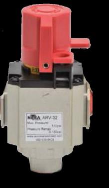
2) Fill the air lubricator with SAE 10 or lighter non-detergent oil (commercially available air lubricator oil). The fill plug is located on the top of unit. Fill until oil level is seen in sight glass and appears full.
3) Set the lubricator oil flow by adjusting knob to #1. Rapid Roller requires a minimum of oil flow into the air supply.
4) Connect to an air supply. The air supply must be capable of delivering 90 psi at the connection. The air connection is made at the inlet port on the air pressure regulator/ lubricator valve. (Nipple not supplied)
5) Set the regulator to 65 psi. The setting is done by pulling up on the adjusting knob, turning (clockwise for higher pressure) and push adjusting knob down to lock. The pressure reading is on the integral regulator gauge
3) Lubricator adjusting knob
5) Regulator adjusting knob, pull up to adjust, push down to lock
4) Inlet to air pressure regulator/ lubricator
5) Regulator gauge
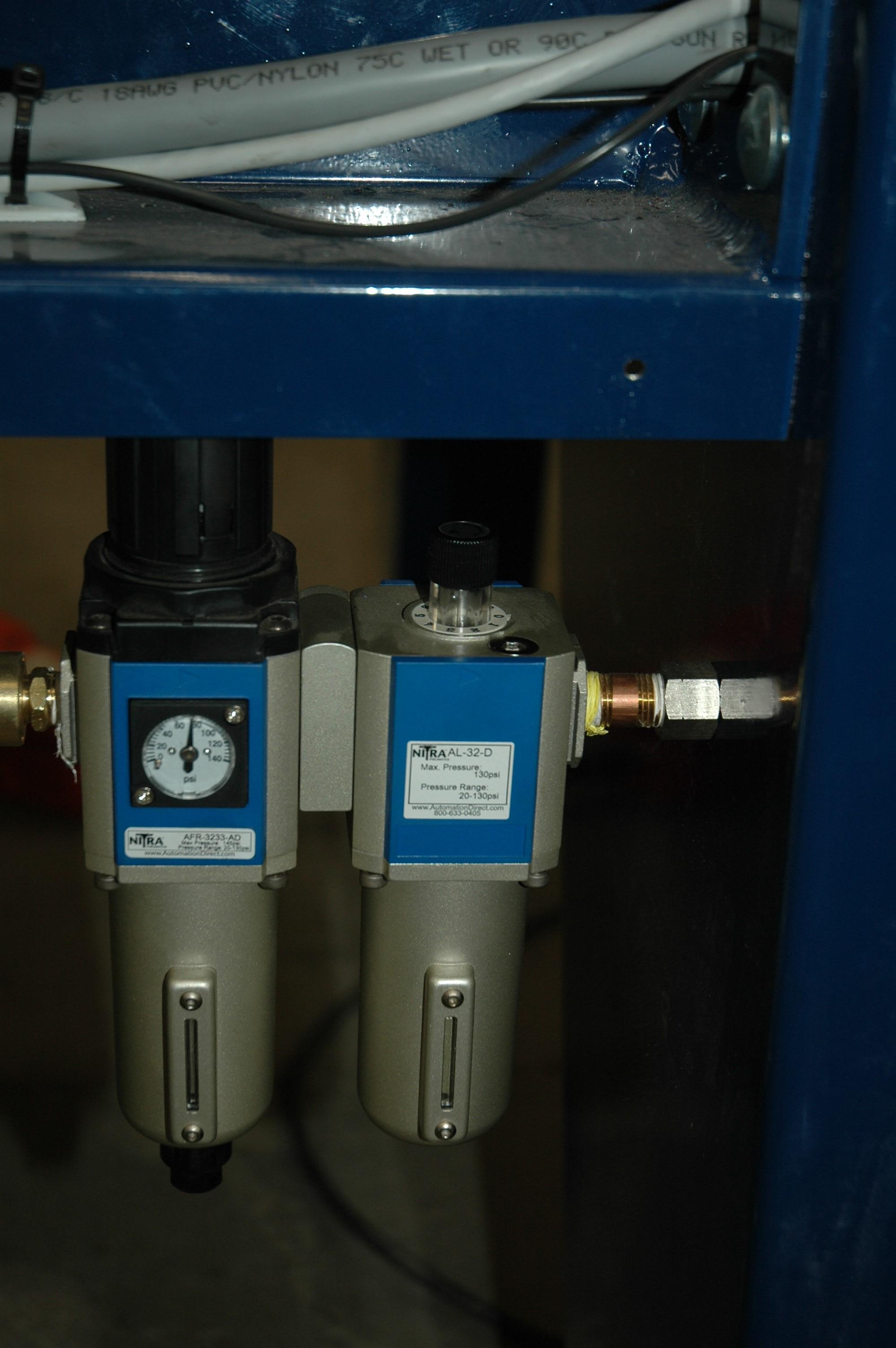
Water trap level and drain, see maintenance section.
2) Lubricator fill plug
2) Lubricator oil level
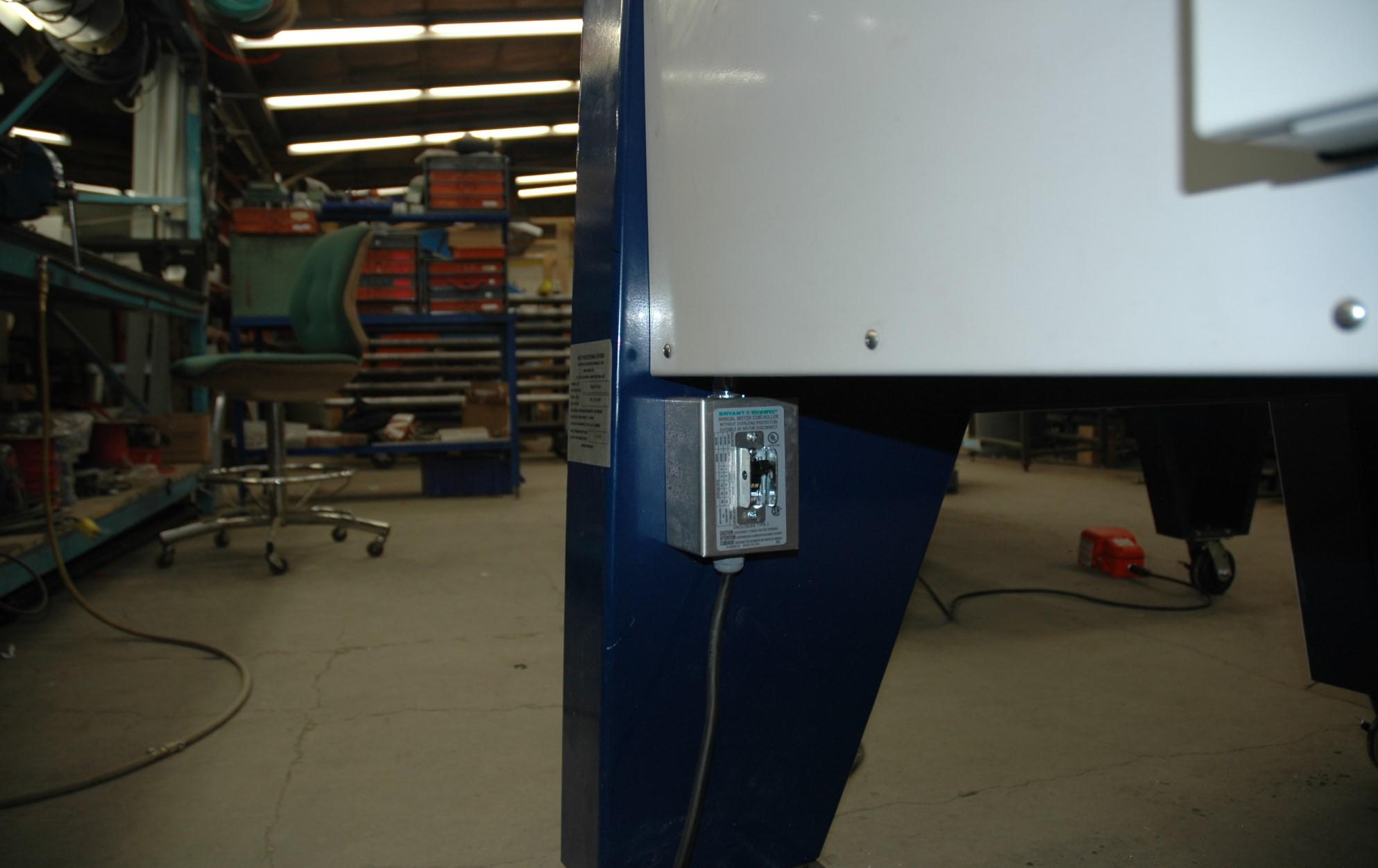
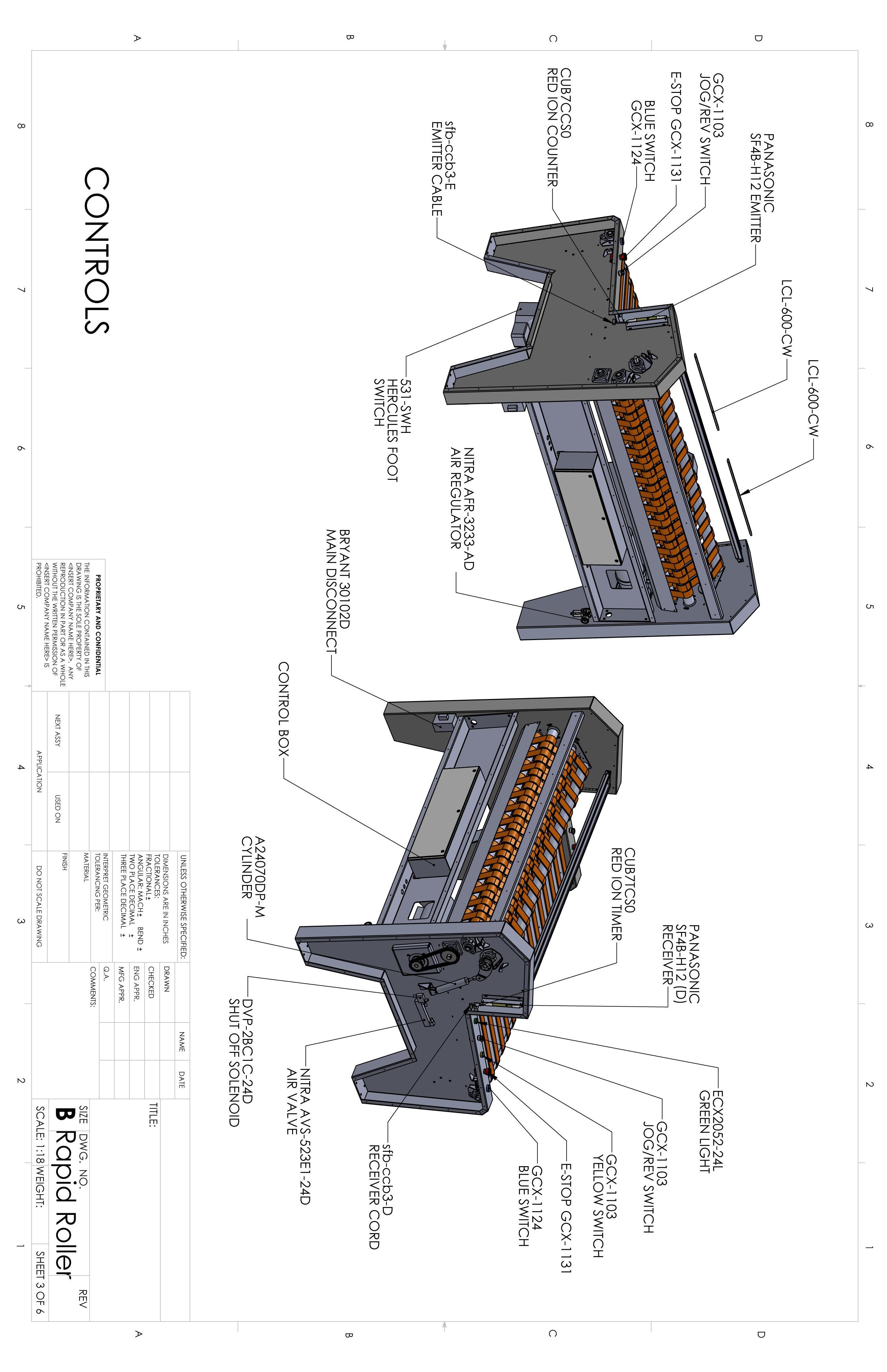
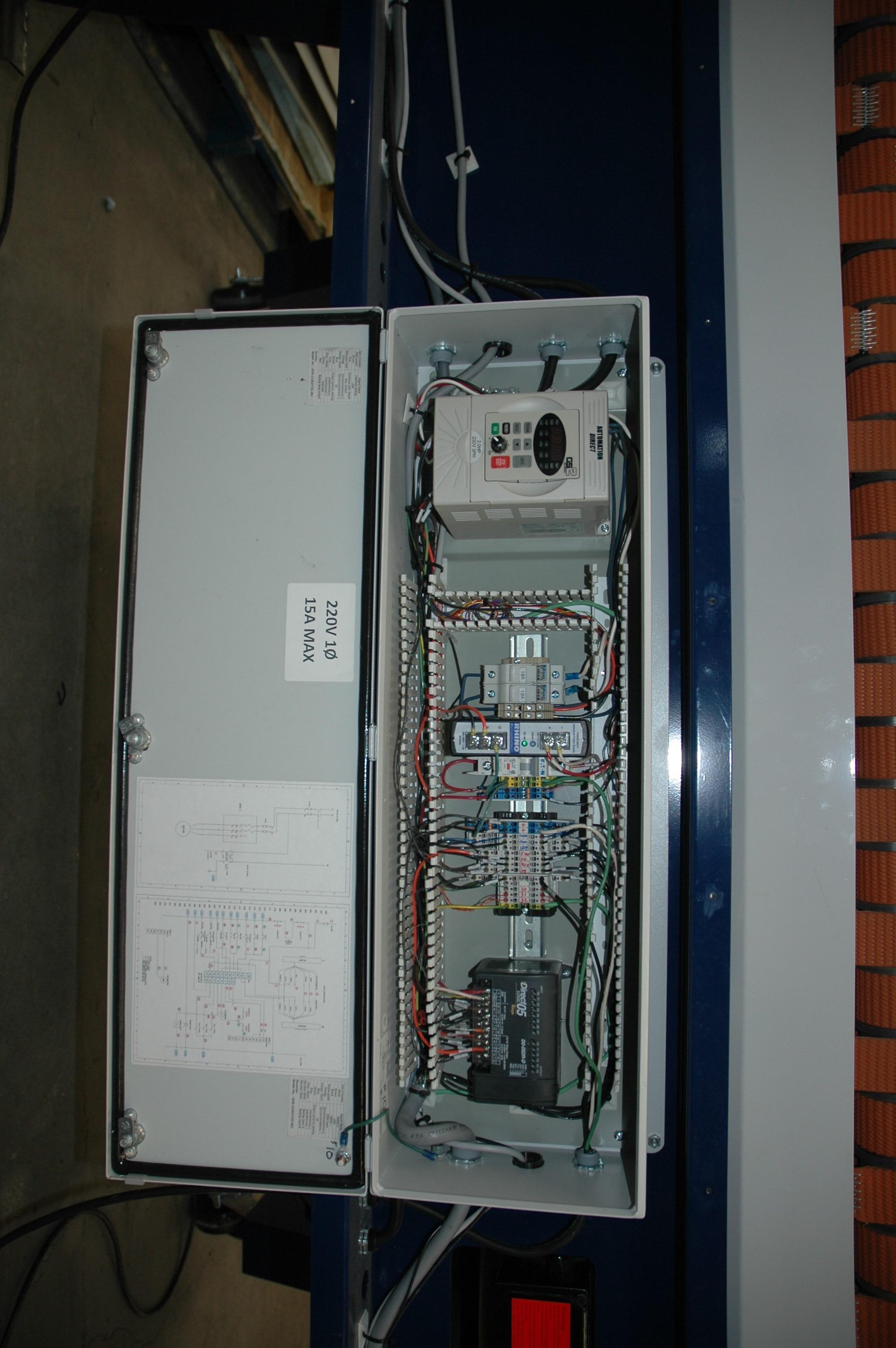
6) The electrical service connection is to be made by a qualified electrician in accordance with national and local electrical codes. Disconnect power before installing. Never wire energized electrical components. Connect the electrical service at the main disconnect switch. The Rapid Roller requires 15 amp, single phase, 240V AC power source. Electrical cable and plug is not supplied.
7) Test equipment ground, this must be performed by a qualified electrician in accordance with national and local electrical codes.
6) Main disconnect switch. Connection to be made by qualified electrician
Injury may result
Caution: Efficient and safe operation of the Rapid Roller requires that each operator reads and understands the following operating procedures and all related safety precautions outlined in the Safety section 5.
The names of the operational controls and instruments are illustrated below. Familiarize yourself with the names and location of each.
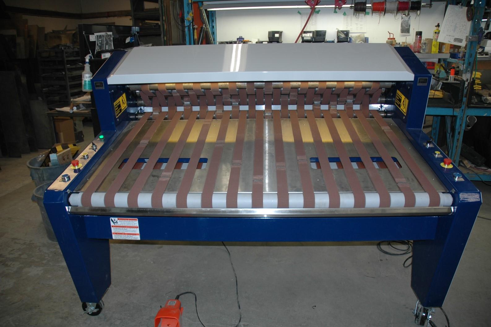
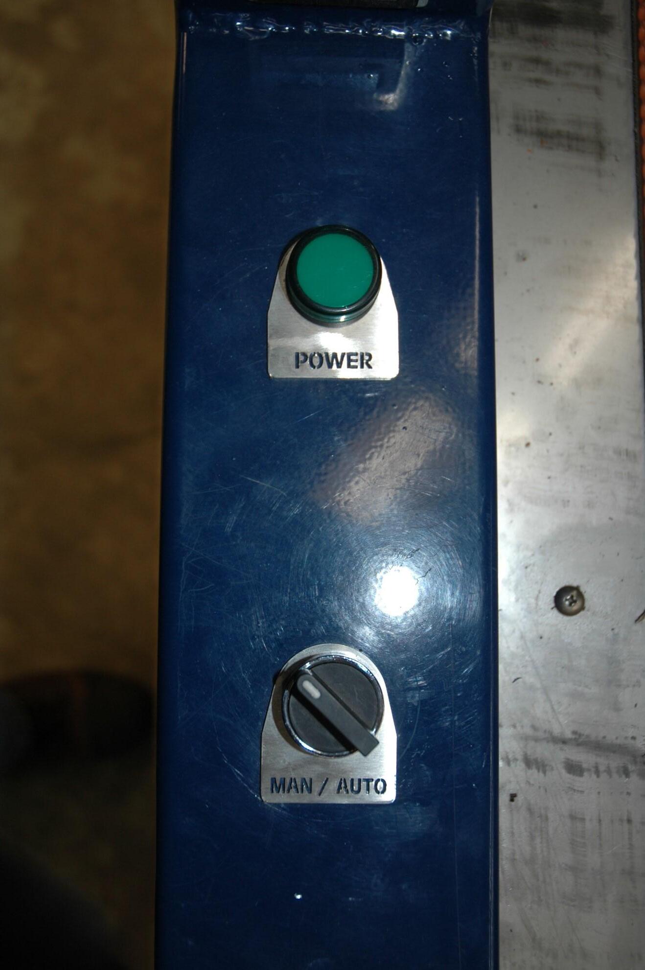
9.2 Power-Up
After the initial setup is complete the power at the main disconnect switch (right hand side at back of machine) can be turned on. After a brief period (3 seconds) the power indicator on the left side of the controls will be illuminated green. The work lights will also be illuminated.

Note: Lack of illumination indicates failure to power up. The machine must be checked by a qualified electrician to determine the problem.
9.3 Auto Mode Operation
Auto Mode Operation automatically reverses the belts at the end of the mat rolling cycle. Reversing the belts helps to send the rolled up mat back to the front of the machine where it is easier to remove to rolled mat from the machine.
Prior to operation:
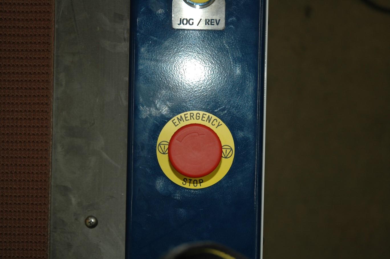
Ensure the Emergency-Stop switches (both sides) are reset. Push for stop and turn clockwise to reset
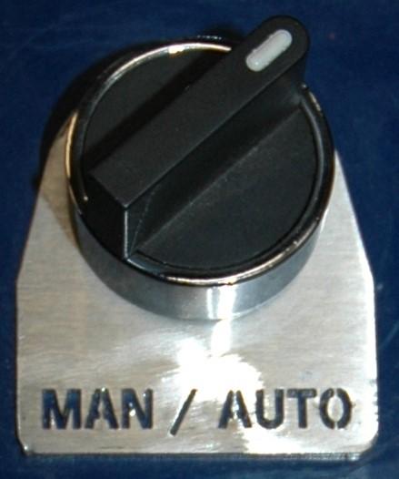
Set the Auto/Manual switch to “Auto”………………….………
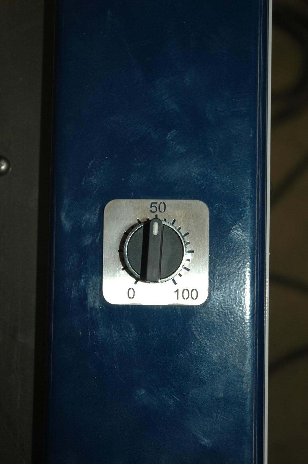
Set the speed control initially to 50………………………………………..…….
Operation:
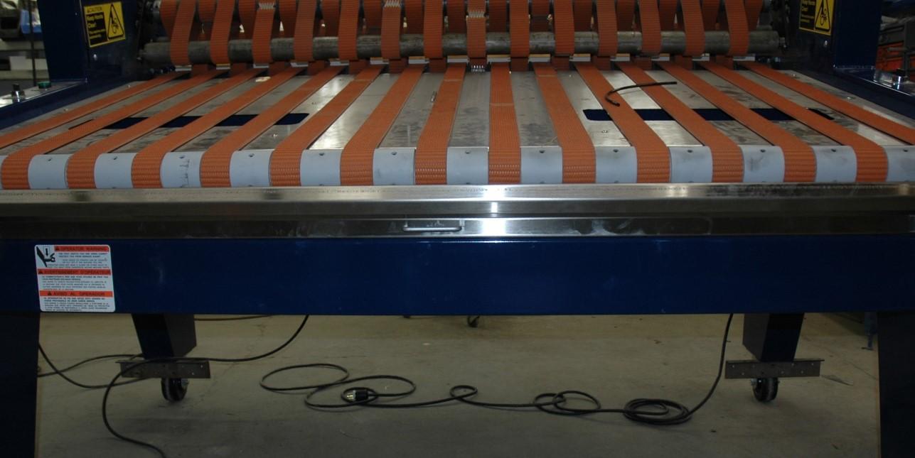
1) Place the mat to be rolled on the belts approximately three quarters of the way up the feed table.
1) Line up the edge of the mat so that it is parallel to the belts.
1) Place mat
2) Align parallel to belts
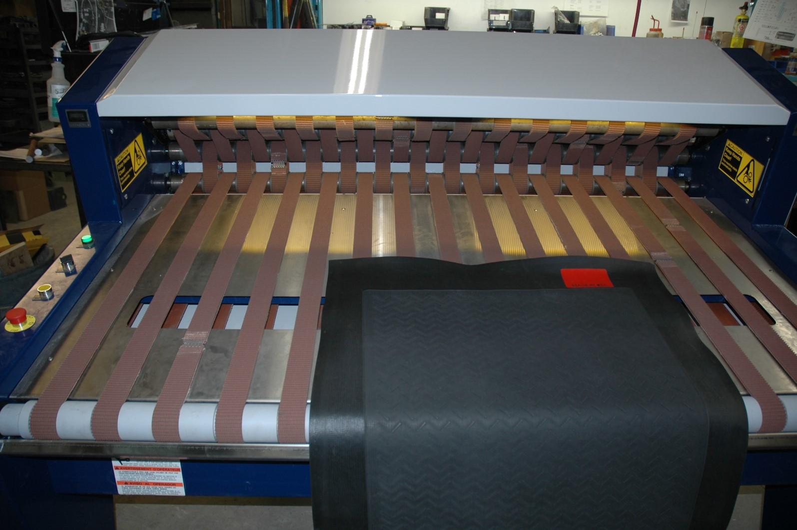
Feed table
2) Use the foot switch or hand switch (see controls) to activate Rapid Roller. The amount of time rolling is controlled by the operator. As long as the hand or foot switch is activated the machine rolls in the forward direction. When the hand or foot switch is released the automatic reverse activates for one second.
3) Remove the rolled mat.
Notes on Auto Mode Operation:
When the hand or foot switch is depressed, Rapid Roller operates on a pre-set program that assists in the mat rolling process. Under the top cover the upper set of belts articulate downward to help form the center of the roll. As the mat roll grows, the upper belts articulate to accommodate the growing mat roll. The rolling cycle is controlled by the operator. At the end of the rolling cycle the upper set of belts articulate upward and release the rolled mat.
Caution: In Auto Mode Operation this is immediately followed by an automated one second reverse cycle.
Upper set of belts articulate downward to help form center of roll
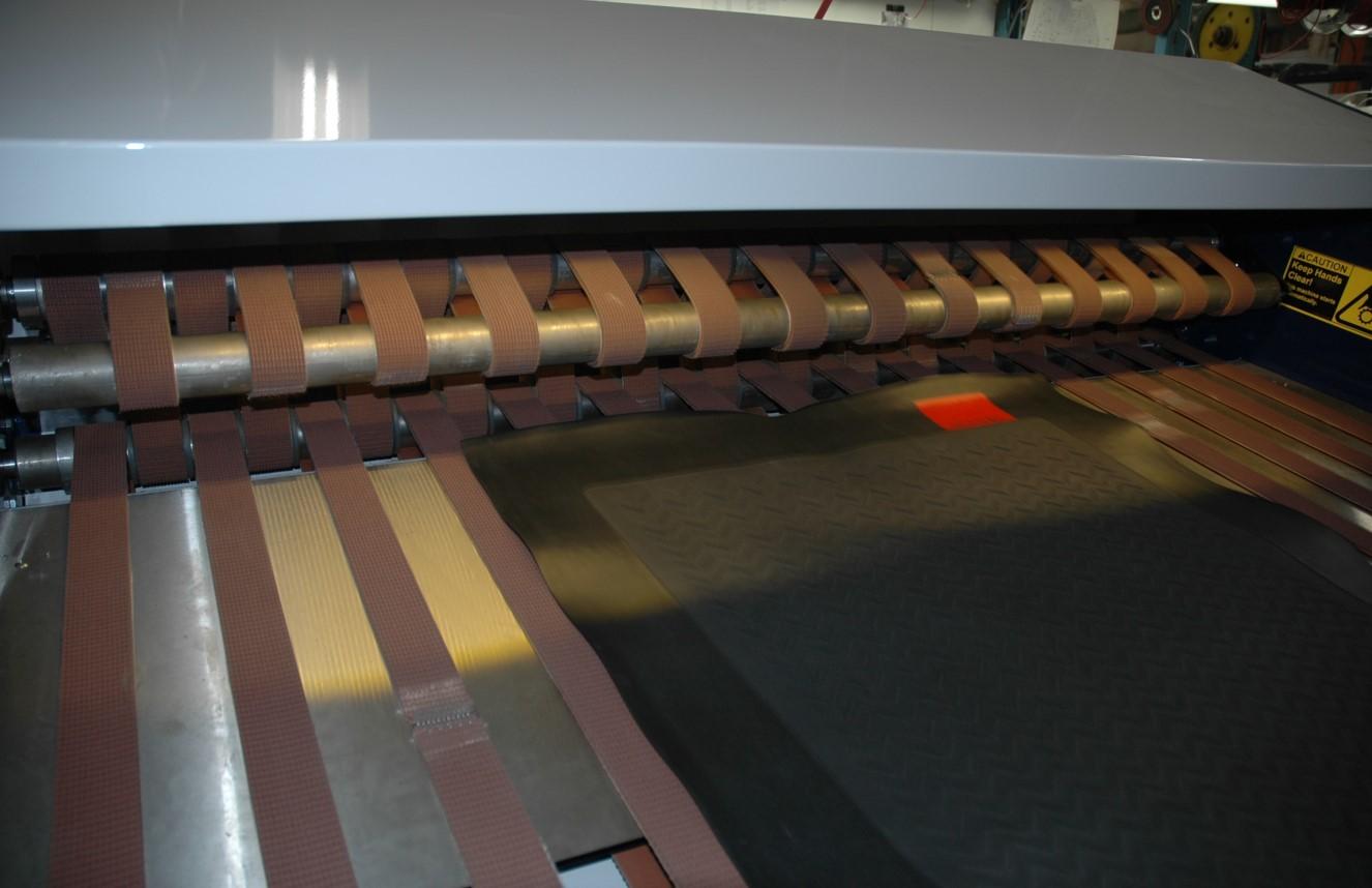
Upper set of belts articulate upward and release the rolled mat
9.4 Manual Mode Operation
Manual Mode Operation operates without automatically reversing the belts at the end of the mat rolling cycle. If desired, the operator can reverse the belts using the jog/rev switch.
Prior to operation:
Ensure the Emergency-Stop switches (both sides) are reset. Push for stop and turn clockwise to reset
Set the Auto/Manual switch to “Manual
Set the speed control initially to 50………………………………….…………..
Operation:
1) Place the mat to be rolled on the belts approximately half way up the feed table.
2) Line up the edge of the mat so that it is parallel to the belts.
3) Use the foot switch or hand switch (see controls) to activate Rapid Roller. The amount of time rolling is controlled by the operator. As long as the hand or foot switch is activated the machine rolls in the forward direction. When the hand or foot switch is released the rolling process stops.
4) Step 4 is optional. Use the jog/reverse switch to reverse the belt direction.
5) Remove the rolled mat.
1) Place mat
2) Align parallel to belts
Feed table
Notes on Manual Mode Operation:
When the hand or foot switch is depressed, Rapid Roller operates on a pre-set program that assists in the mat rolling process. Under the top cover the upper set of belts articulate downward to help form the center of the roll. As the mat roll grows, the upper belts articulate to accommodate the growing mat roll. The rolling cycle is controlled by the operator. At the end of the rolling cycle the upper set of belts articulate upward and release the rolled mat. The operator has the option to use the jog/reverse switch to move the mat from the rolling area to the front of the machine.
Upper set of belts articulate downward to help form center of roll
Upper set of belts articulate upward and release the rolled mat
9.5 Operational Features
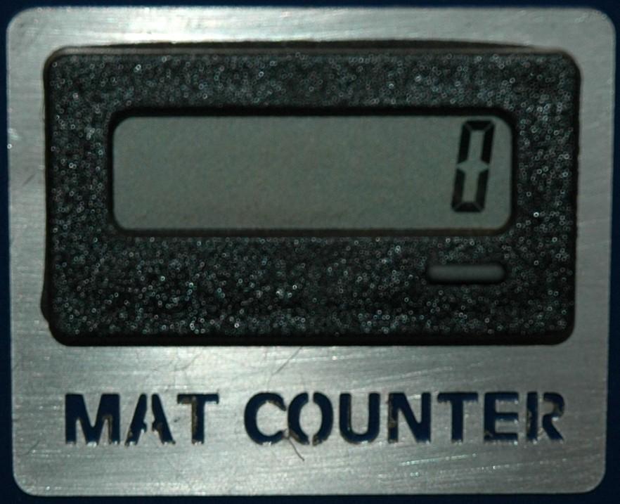
Hour Meter and Mat Counter
1) The Hour Meter displays the total number of hours the main disconnect switch is “on” while connected to a power source. The Hour Meter cannot be reset or adjusted. Use the Hour Meter to keep track of service intervals (see Maintenance section).
2) The Mat Counter displays the total number of cycles the machine has run since the last reset. The Mat Counter can be reset with the reset button.
Buttons are inactive

Mat counter reset button
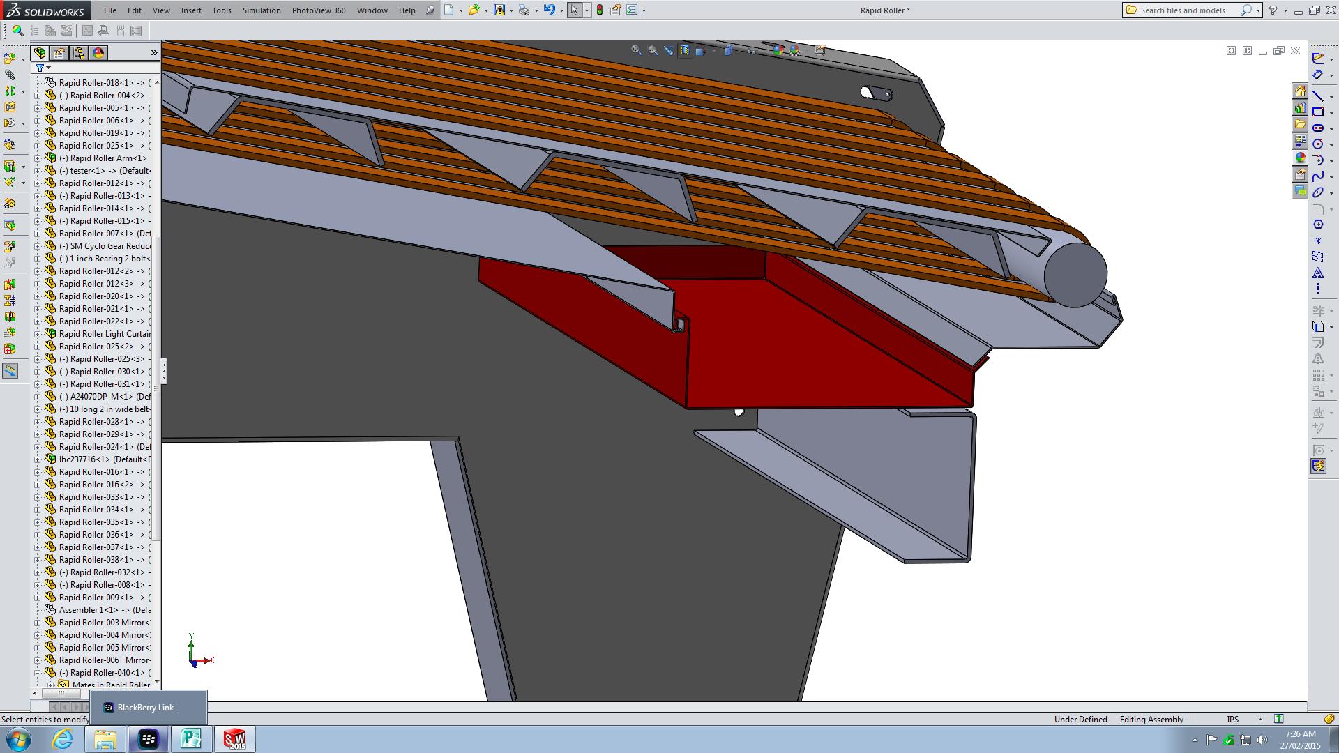
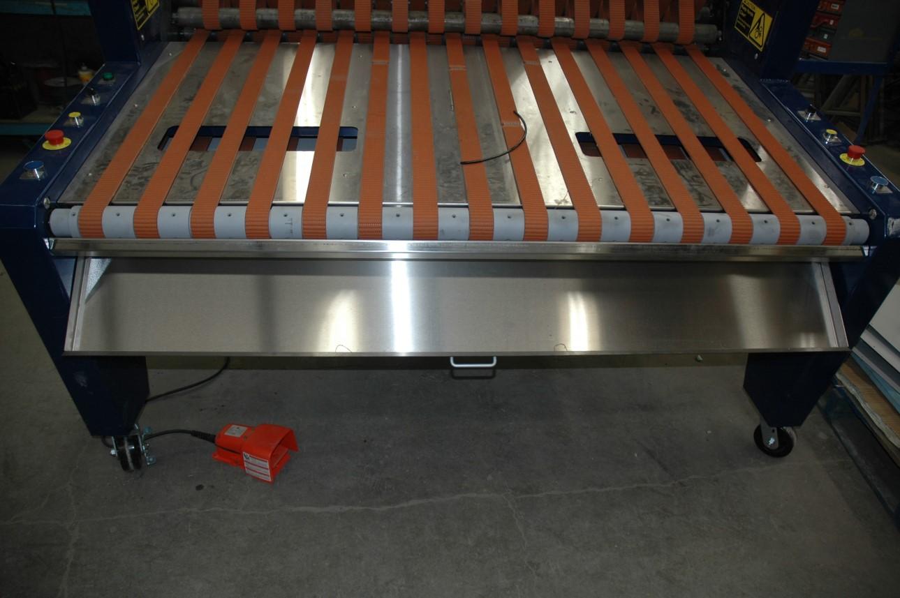
Dust Tray
The Dust Tray collects debris that falls off the mats during the rolling process. It can be opened for debris disposal and cleaning.
Note: Check before operating to Ensure the Dust Tray is in place. If the Dust Tray is out of place it may interfere with the operation of the machine and may cause damage to the belts. To remove the Dust Tray:
1) Turn main disconnect switch OFF
2) Push up on the bottom of the Dust Tray
3) Unhook the back edge of the Dust Tray from the machine
4) Using the handle provided, pull the Dust Tray forward and remove debris
5) Replace the Dust Tray prior to operation
Section drawing of Dust Tray
3) Unhook the back edge of the Dust Tray
2) Push up on the bottom
4) Pull Dust Tray forward
5) Replace the Dust Tray
Light Curtain Safety Switch
The Light Curtain Safety Switch is an electronic device that stops the machine if an object interferes with the sensing grid. The sensing grid area is illustrated below.
Injury may result
Caution: Do not adjust, bypass or tamper with the Light Curtain Safety Switch, injury may result. The Light Curtain Safety Switch is designed to help protect the operator. If the Light Curtain Safety Switch is activated while the machine is running, the machine will stop. Remove the object from the sensing area.
To reset the Light Curtain Safety Switch:
Reset by activating and resetting the Emergency-Stop. (Push to activate, turn clockwise to reset). Normal operation may resume.
Light Curtain Safety Switch sensing grid.
Highlighted in red for illustration purposes.
Variable Speed Control Switch
The rolling cycle speed can be controlled by adjusting the Variable Speed Control Switch. The speed control can help match the operators abilities to the machine.
ECP - Lockout / Tagout Procedure for Personnel Safety
This ECP (Energy Control Procedure) is required to ensure personal safety due to a trapped air drop hazard. The drop arm/bar may drop down unexpectedly trapping or injuring personnel. Please ensure the following procedure has been completed prior to preforming maintenance, removing trapped products or inserting fingers into the working mechanism of this machine.

Ensure drop arm/bar is in the lowered position, if not repeat steps in the correct order
10 Maintenance
8 hrs or every shift - Check Light Curtain Safety Switch function.
To check the light curtain safety switch function:
1) Use the foot switch or hand switch (see controls) to activate Rapid Roller.
2) Using an object such as a broom handle (do not use your arm or body parts), position it so that it interferes with the light sensing grid as depicted below.
3) The machine must immediately stop. If it does not stop, the system requires service. Do not operate the machine. Contact CDF Systems Service Department for detailed service instructions. (see Page 3.)
Injury may result
Caution: To prevent serious injury, make certain the main disconnect switch is in the OFF position, air supply is disconnected and the power source is disconnected before performing the following maintenance procedures. Always follow the safety instructions, Section 5.
1000 hrs - Check Bearings
1) Open the side panel access covers by removing the hardware.
2) Inspect the bearings for signs of failure. Locate the grease zerk at each bearing housing.
3) Lightly grease each bearing. 1 pump by hand operated grease gun using Lithium based EP2 Grease. There are 4 bearings on each side of the Rapid Roller that require grease.
4) Replace side panel covers.
Caution: To prevent serious injury please follow the ECP - Lockout / Tagout Procedure for Personnel Safety on page 25. Always follow the safety instructions, Section 5.
Right side grease points, 4 places, 1000 hrs
Left side grease points, 4 places, 1000 hrs
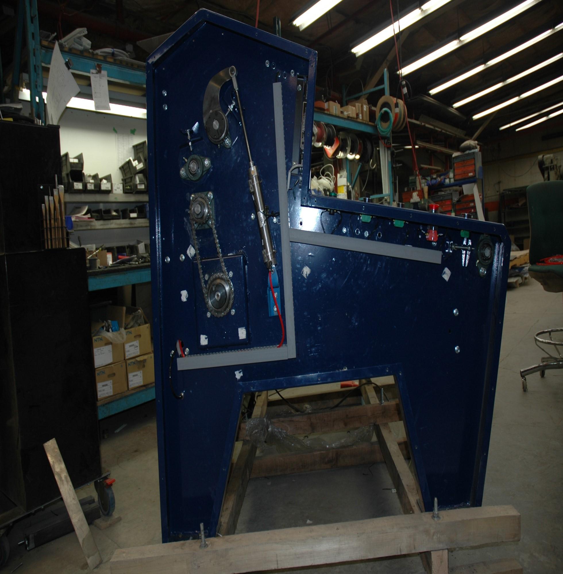
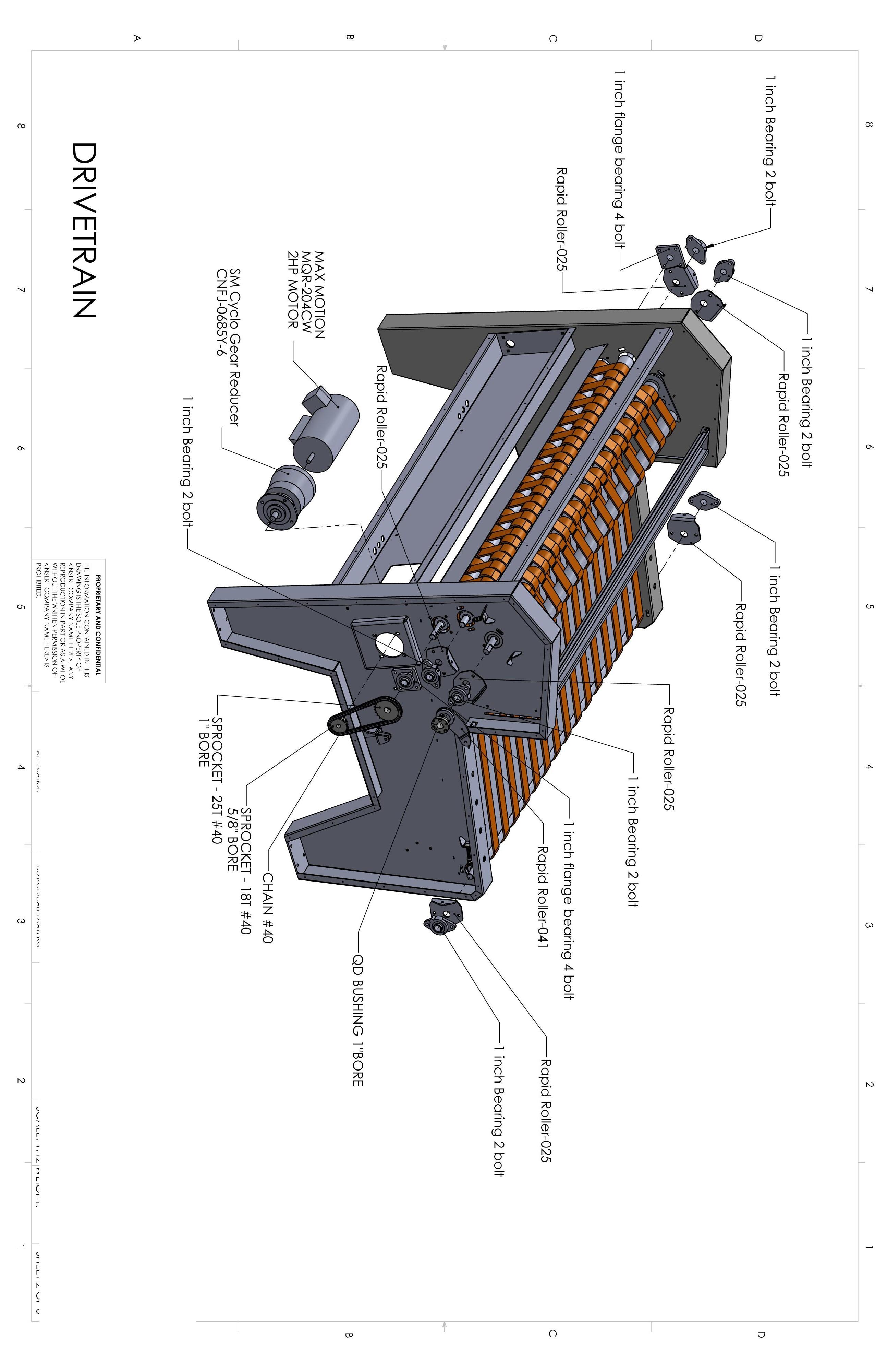
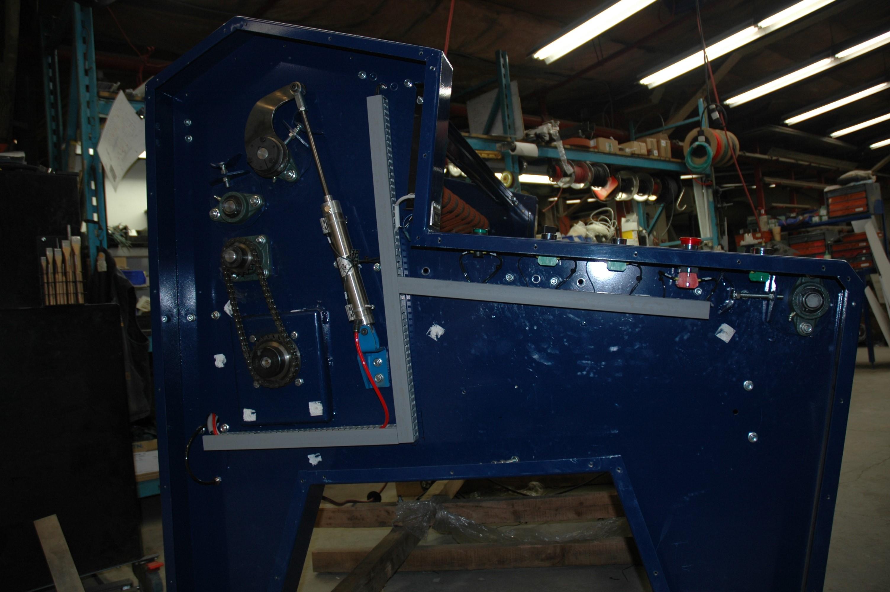
1000 hrs - Check Chain Condition and Adjust
1) Open the side panel access covers by removing the hardware.
2) Inspect the chain for signs of failure.
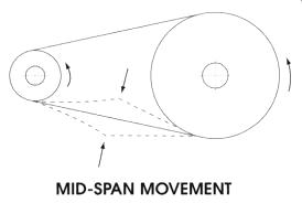
3) Check chain tension. 1/8” to 3/8” slack side - mid span movement is required. To adjust, loosening 4 hex-nuts at lower sprocket. Sliding lower sprocket up or down to achieve adjustment. Note: Support the weight of motor and gearbox connected to the lower sprocket shaft while making adjustment.
4) Retighten hex-nuts after making adjustment.
5) Lightly oil chain with chain oil. Remove excess oil with cloth.
6) Replace side panel covers.
Note: Replace chain if stretched beyond the adjustment allowance.
Chain
Hex-nuts at lower sprocket
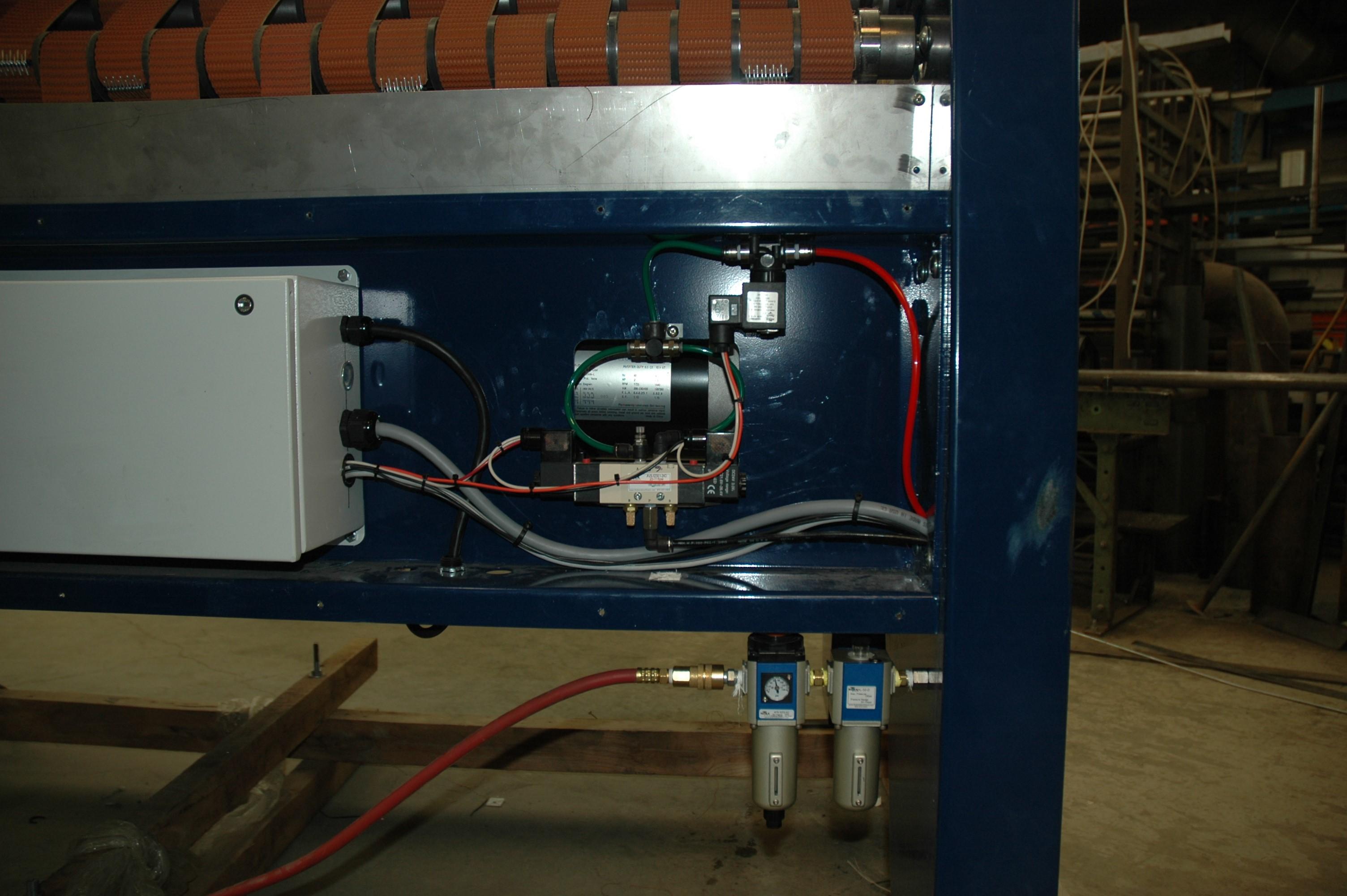
100 hrs - Check Air Lubricator, Regulator Pressure and Drain Water from Regulator Water Trap
Note: A shorter service interval may be required if oil is used up or regulator water trap is full.
1) Observe the oil level in sight glass. If required, fill until oil level is seen in sight glass and appears full. Fill the air lubricator with SAE 10 or lighter non-detergent oil (commercially available air lubricator oil). The fill plug is located on the top of unit.
2) Check the lubricator oil flow setting (set to #1 on knob). See Pre instructions.
3) Check the regulator setting (set to 65 psi). See Pre
4) Observe the water level in sight glass of regulator. Drain water by opening plug on bottom of the regulator.
Lubricator fill plug
Lubricator oil level
Regulator water trap level
Regulator water trap drain
Caution: To prevent serious injury please follow the ECP - Lockout / Tagout Procedure for Personnel Safety on page 25. Always follow the safety instructions, Section 5.
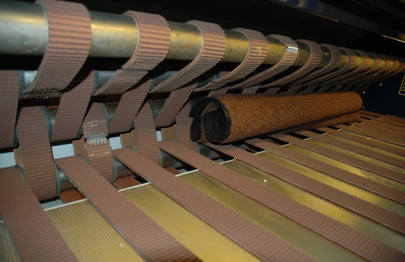
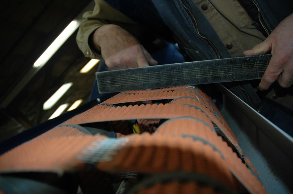
1000 hrs - Check Belt Condition and Tension
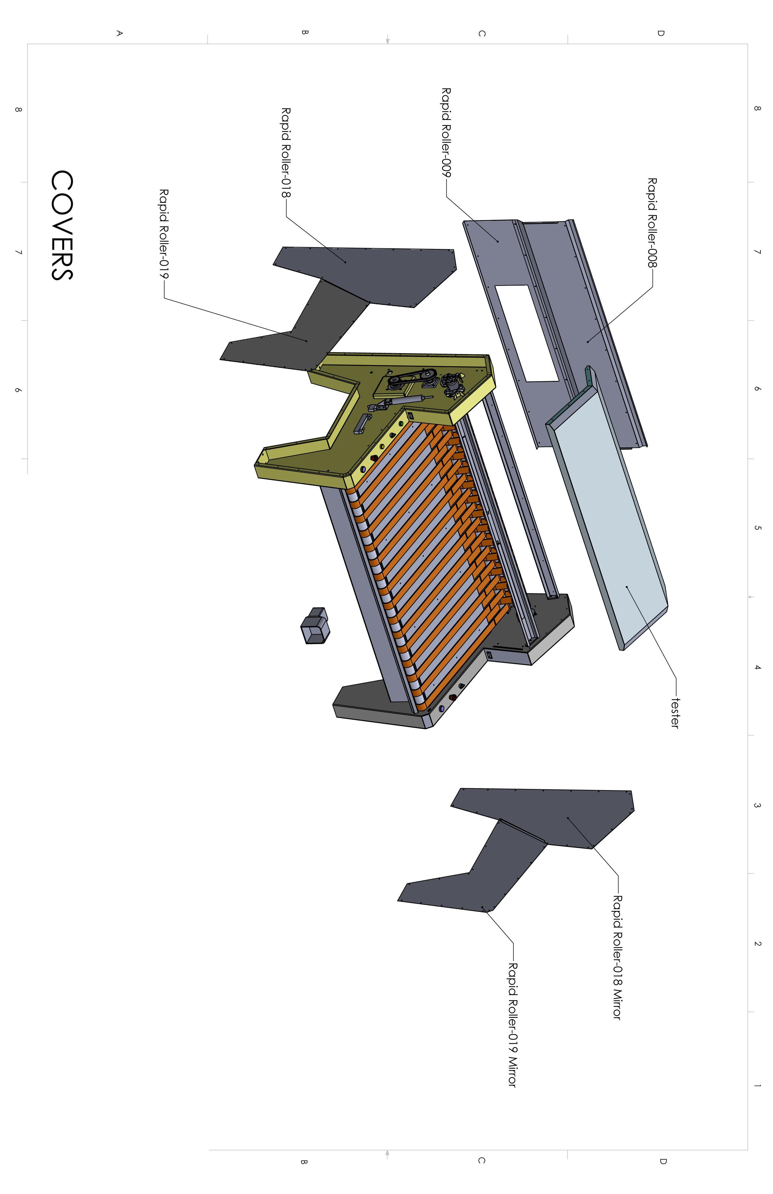
Note: Remove access covers as required, top, rear and sides. Replace covers after adjustments are made.
1) Observe the condition of the belts. Belts may need replacement if torn, missing lacings or tread is worn.
2) Check short belt tension, there are three sets of short belts. 1/8” to 1/4” deflection is recommended. Note: Belts must be adjusted in order. Adjust short belts working outwards from the drive roller shaft. Adjust the roller arm belts last. Loosen bearing mounts. Adjust tension evenly on both sides using adjusting bolts. Tighten bearing mount bolts after adjustment.
3) Adjust the roller arm belts (third set) . Loosen shaft mount jam-nuts at the end of the roller arms. Adjust tension evenly on both sides using adjusting bolts. Tighten jam-nuts after adjustment.
2) Short belts, 3 sets. At mid span, push with finger, measure distance using straight edge from top of belt. 1/8” to 1/4” deflection is recommended. Belts must be tensioned in order.
Drive roller shaft
Adjusting bolt for long belts
Adjusting bolt for 1st set of short belts
Loosen bearing mount bolts, typical.
Adjusting bolt for 2nd set of short belts
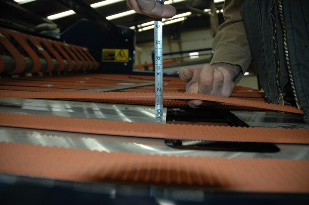
4) Check long belt tension. 3/4” to 1-1/2” deflection is recommended. These belts can be adjusted without affecting the three sets of short belts. Loosen bearing mounts. Adjust tension evenly on both sides using adjusting bolts
Adjust with bolt
Caution: To prevent serious injury please follow the ECP - Lockout / Tagout Procedure for Personnel Safety on page 25. Always follow the safety instructions, Section 5.
Loosen jam-nut
Roller arms
4) Long belts. Lift with finger, measure distance from deck to bottom of belt. 3/4” to 1-1/2” deflection is recommended.
1000 hrs - General Machine Inspection
Note: Remove access covers as required, top, rear and sides. Replace covers after inspections are made.
Ensure safety signs are in place and readable (see Safety section 5.3 Safety SignsLocations and Decals) Order and replace any missing or damaged safety signs
Ensure all wiring harnesses are tied away from moving parts
Check for loose hardware, tighten as required
Clean debris and dust from behind service covers
Caution: To prevent serious injury please follow the ECP - Lockout / Tagout Procedure for Personnel Safety on page 25. Always follow the safety instructions, Section 5.
11. Service Parts
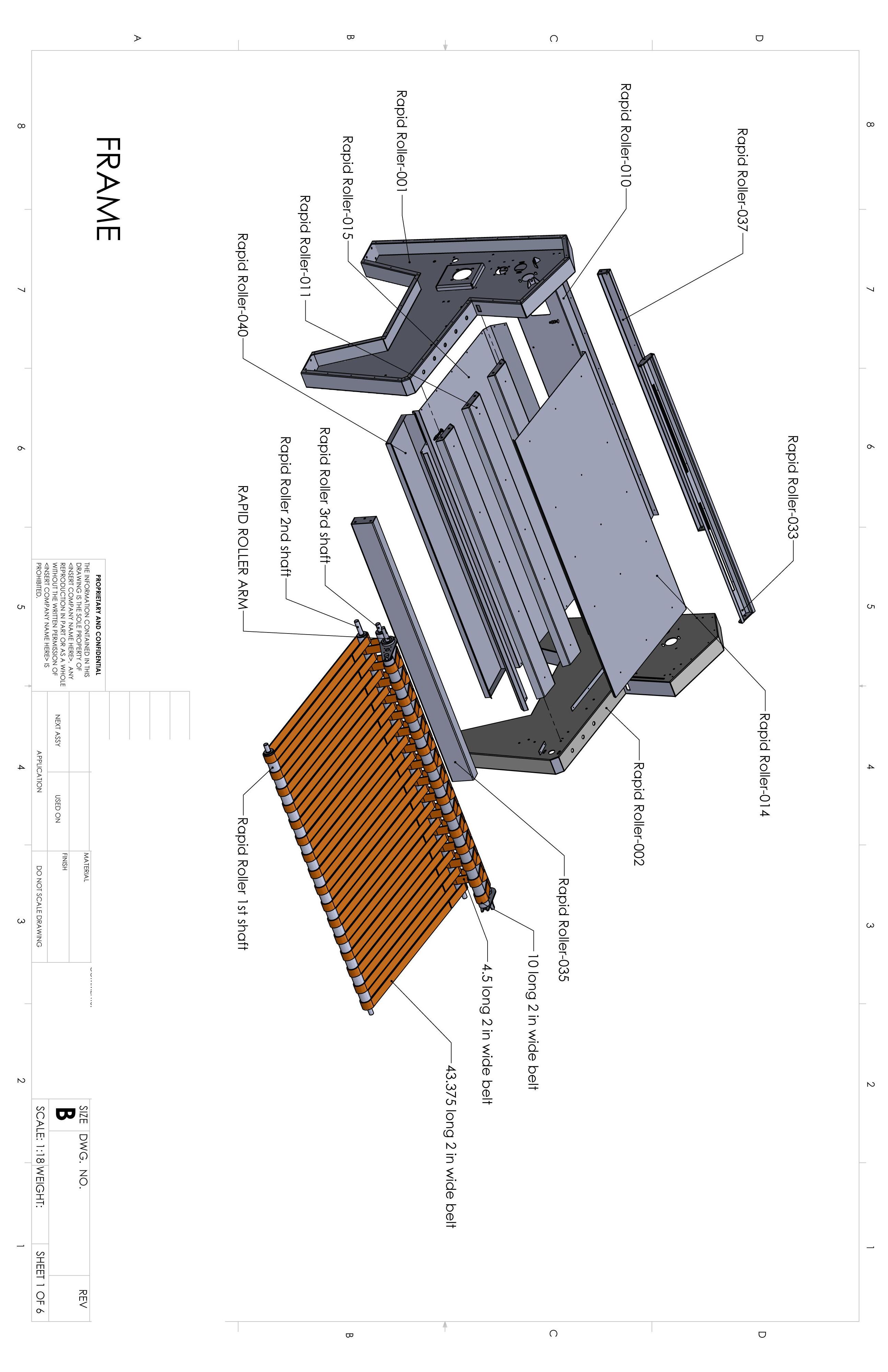
11.1 Frame
Part # Description
RR100021 Belt, Long
RR100022 Belt, Short, 1
RR100023 Belt, Short, 2
RR100064 Belt, Moving Arm
RR100024 Frame, Front
RR100025 Frame, RH Side
RR100026 Frame, Belt Table
RR100027 Frame, Light Bar
RR100028 Frame, Back, Upper
RR100029 Frame, Back, Lower
RR100030 Frame, LH Side
RR100031 Frame, Lower Belt Table
RR100032 Frame, Table Support
RR100033 Dust Tray
RR100034 Shaft, First Assembly
RR100035 Shaft, Second Assembly
RR100036 Shaft, Third Assembly
RR100037 Shaft, Fourth Assembly
RR100065 Shaft, Arm Assembly
RR100001
RR100002
RR100003
Part #
RR100042
RR100043
RR100044
RR100045
RR100046
RR100046
RR100045
RR100044
RR100043
RR100042
CDF Systems
Unit #6, 20113– 92 a Ave
Langley B.C. V1M 3A5
1-800-986-6702