
SELECTED WORKS 2023 FARHEEN SIRAJUDDIN
PROJECTS 01 STAIRCASE AND HANDRAIL Ashed- Orchard Facility 02 THE HIVE Bee Research Facility 03 CONTEMPORARY ART MUSEUM OF OMAHA 04 TRIPOD LAMINATED CHAIR ACADEMIC PROFESSIONAL Fall 2017 - Spring 2018 Spring 2018 Fall 2018 Product design 05 FORD CONSERVATION CENTER Masonry Repair 06 WAYNE COUNTY COURTHOUSE Exterior Restoration 07 BALAJI’S RESIDENCE Chimney Removal and Re-pointing Surface Gutter Addition Architecture + Interior Design
AND HANDRAIL ASHED
South Sioux City, Nebraska
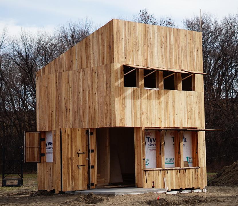
Staircase and handrail project is a team work by two students. Here we explored different materials and methods of fabrication using the lamination technique to blend with the Cross Laminated Timber construction of ‘Ashed’.

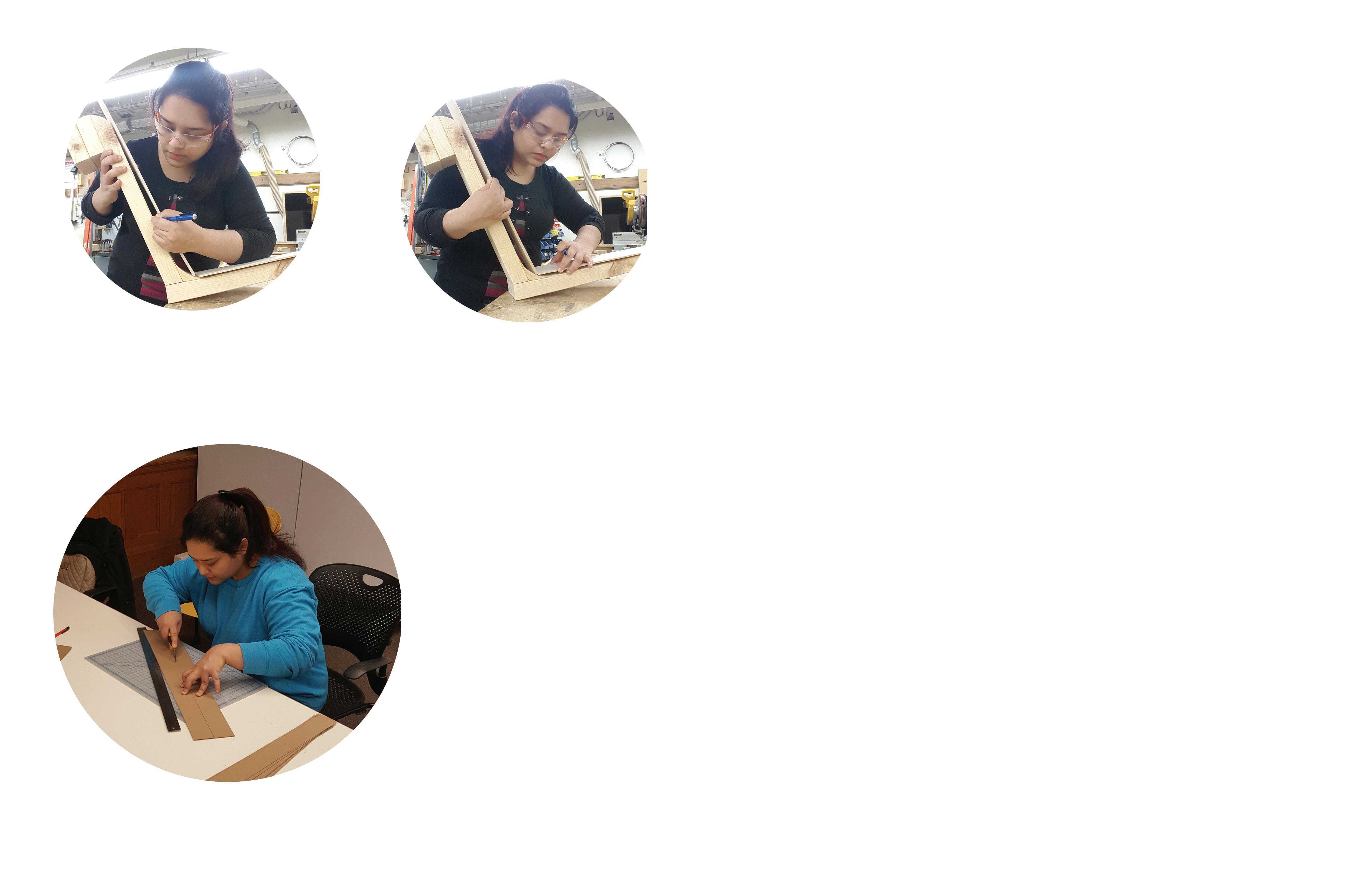
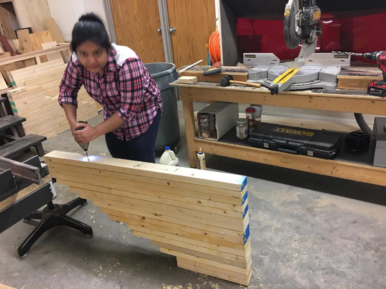
My role involved addressing and solving the issues related to fabrication as we began designing and fabricating the parts in the school’s workshop. The project demanded high level of accuracy and craftsmanship, and ownership of the work produced. The process involved preparation of working drawings/ installation drawings which were provided to the contractors for reference during installation.
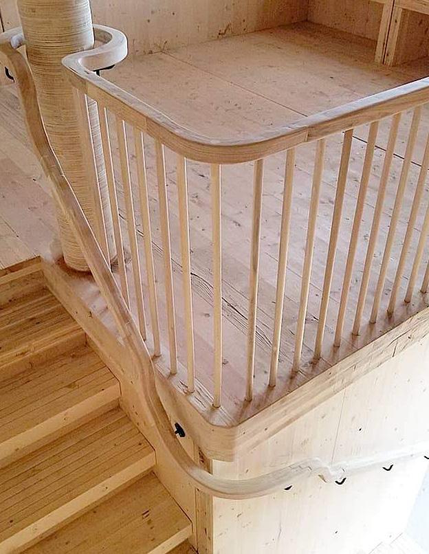
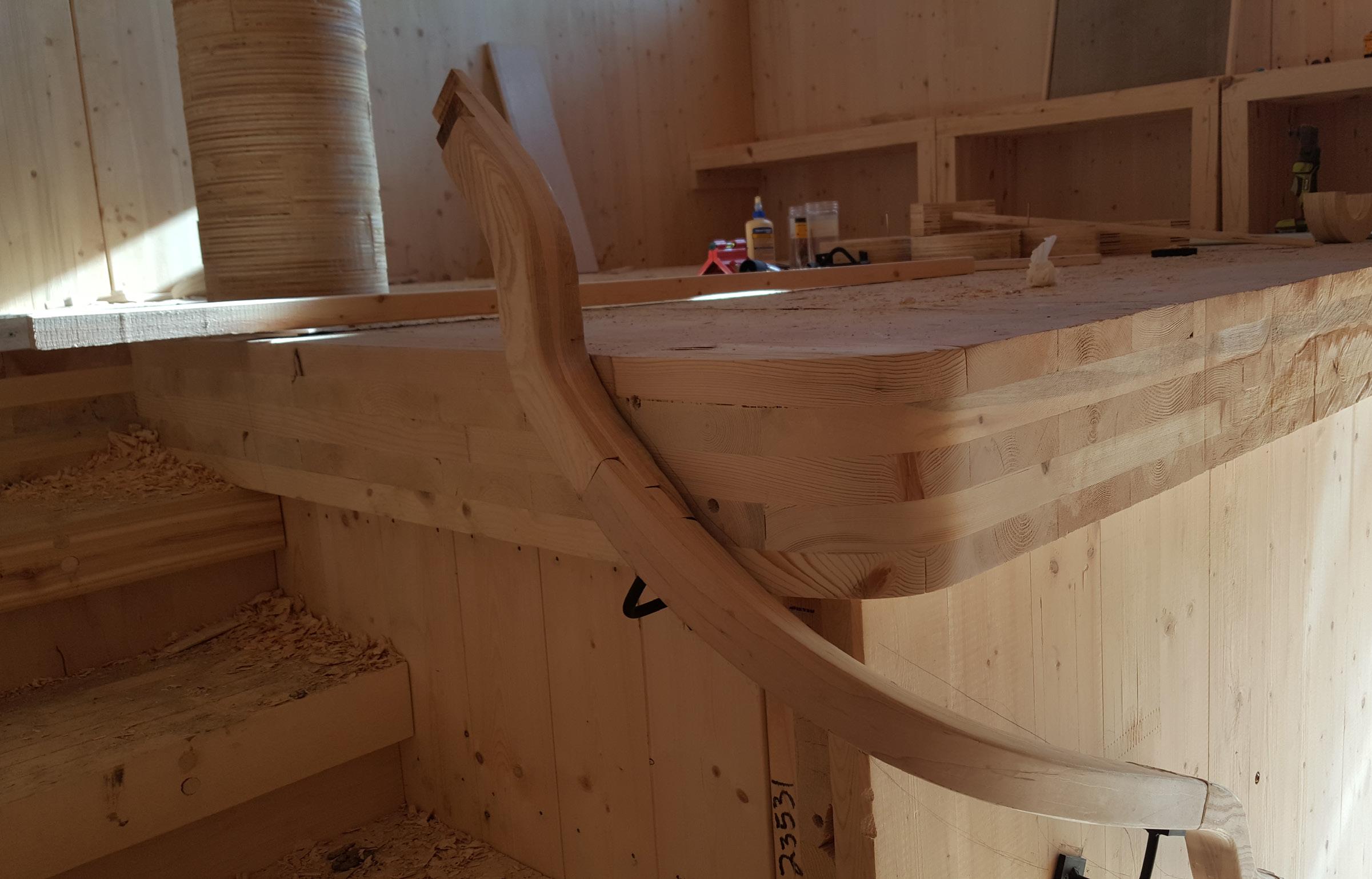
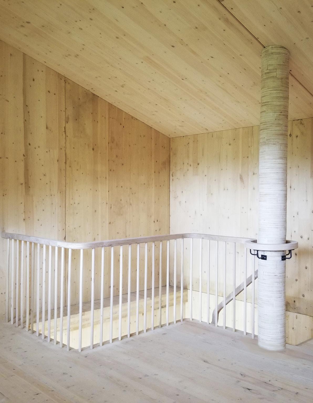
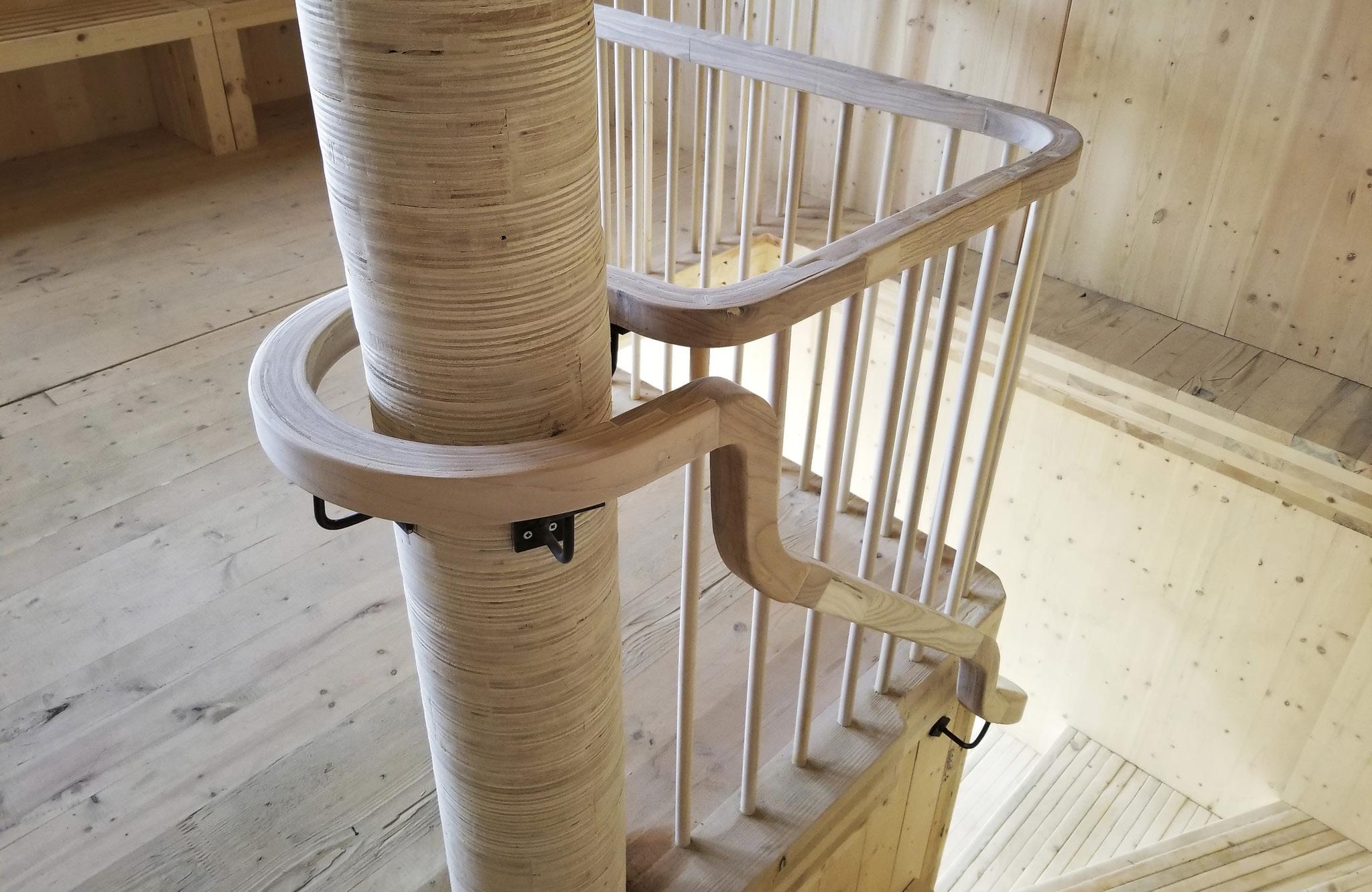
Handrail follows the steam bending and glue lamination technique which gave us the flexibility to achieve a sinuous form. It was fabricated as eleven pieces which were installed on site by the students.
Materials used:
Staircase- SPF 2x4 wood and birch ply
Handrail and column-Reclaimed Ash strips
Faux column - Birch ply

01 STAIRCASE
Design build studio - Fall 2017
Level 1 -plan
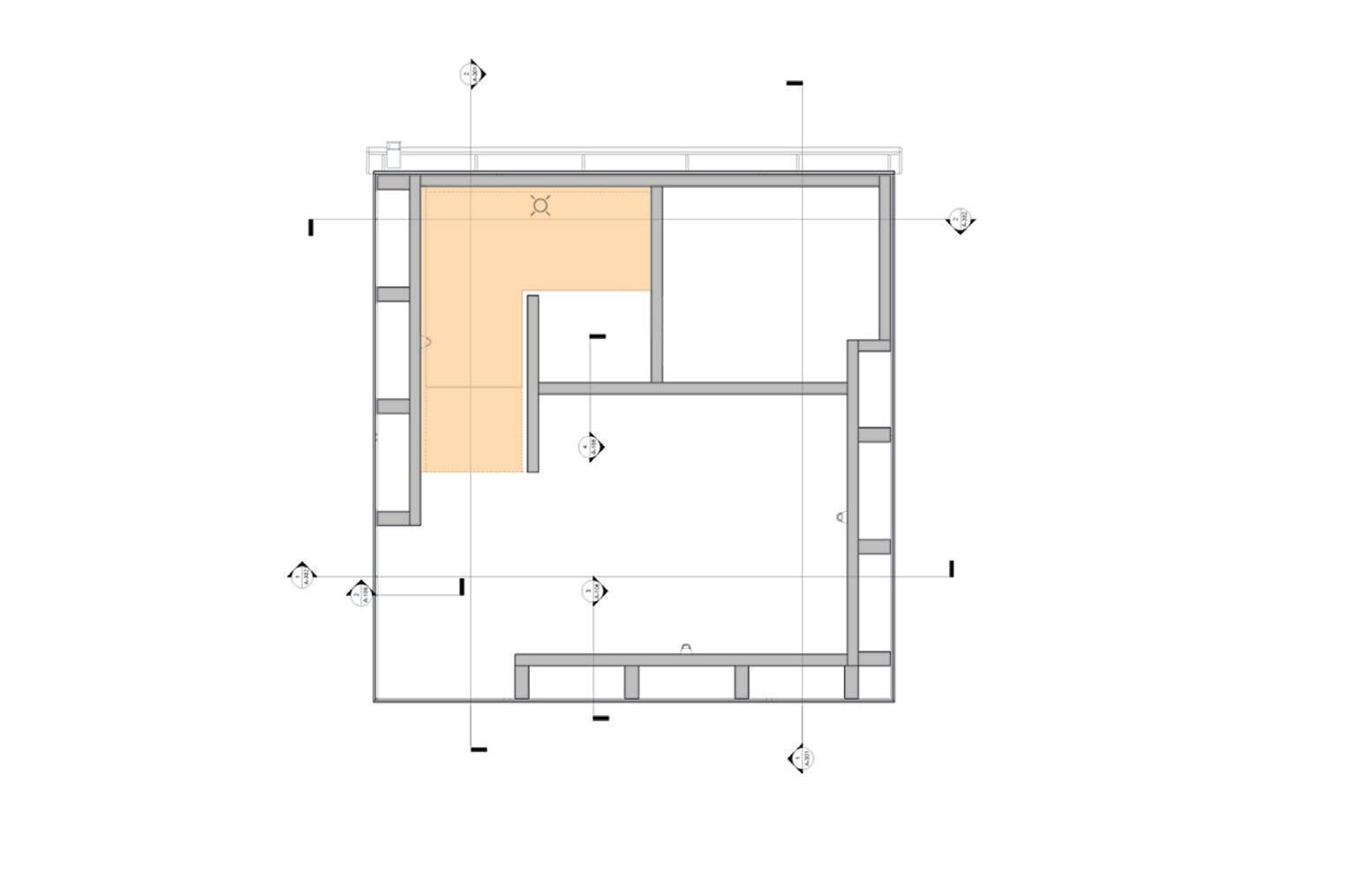
Staircase plan
‘ASHED’ - an Orchard Facility
up
entrance
Stud wall addition for stair support
toilet
staircase up
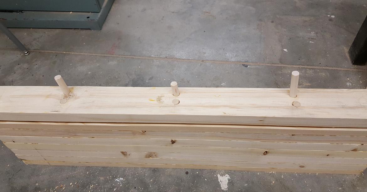
Angled dowel insertion
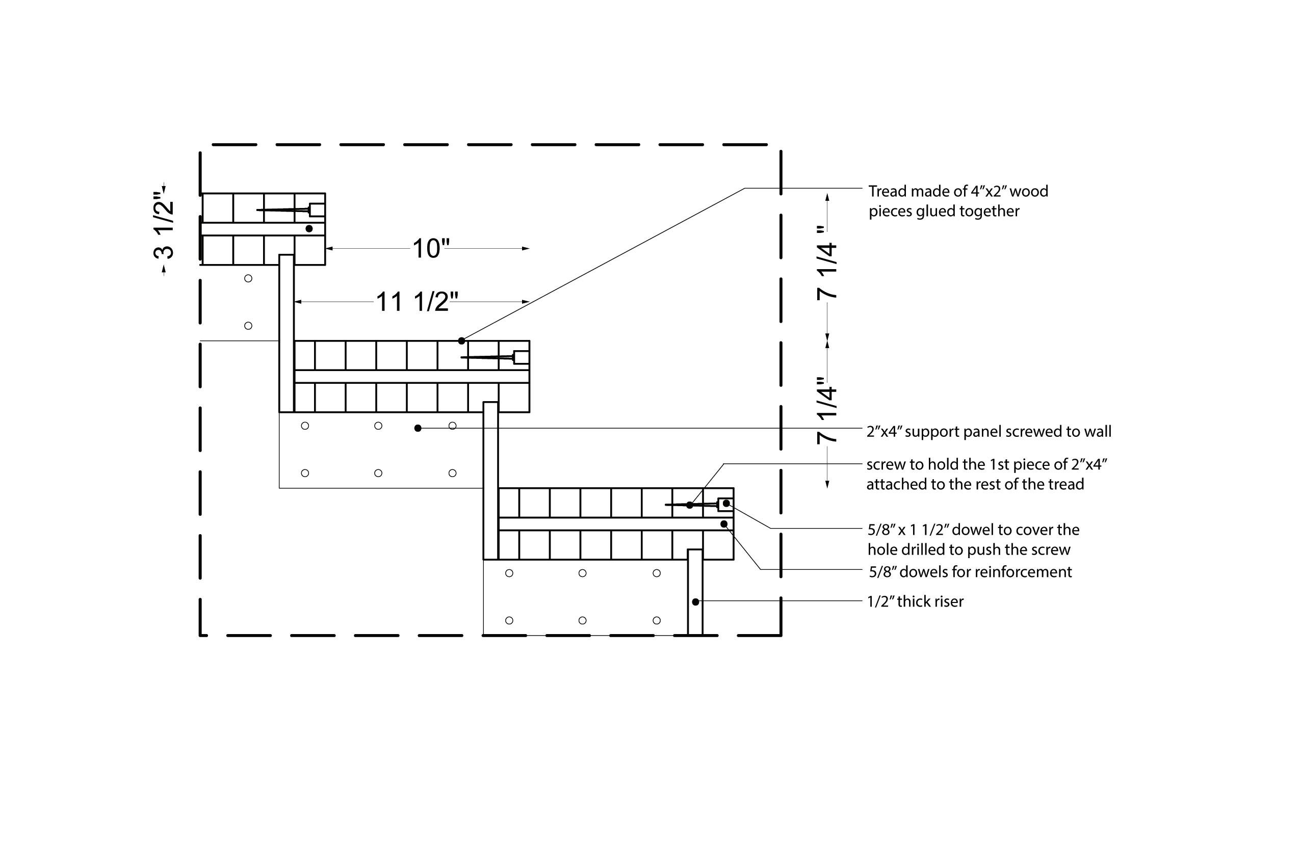
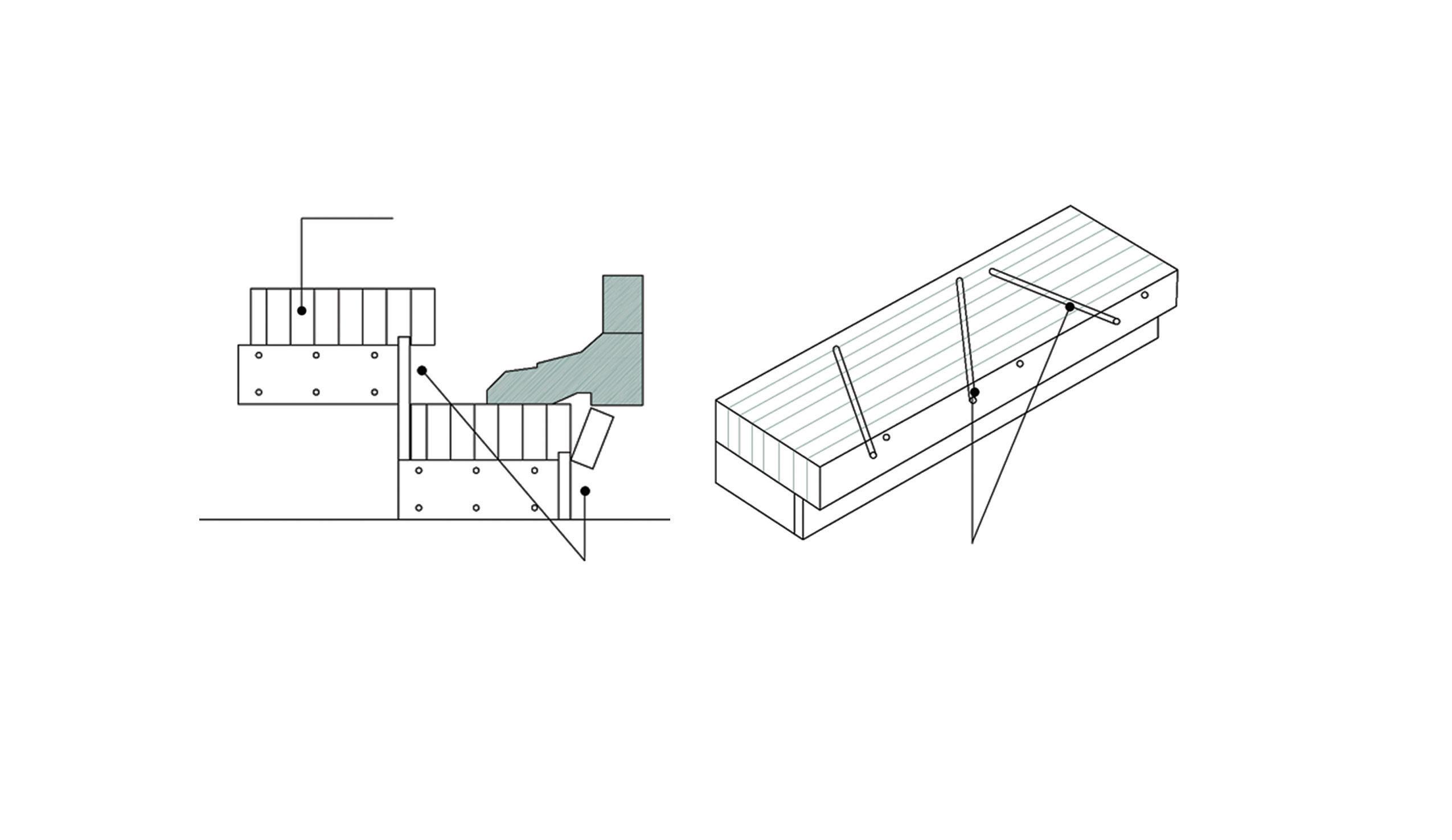

Lack of support
Lack of support under the first glued 2x4 leaves it vulnerable to pressure. Hence it is secured in place by drilling 3 screws through the 1st 3 pieces to keep it from falling apart. Also, the tread is reinforced by inserting glue coated dowels at different angles.
Tread reinforcement
Detailed section through stair treads
Stud
wall for supporting staircase 4” thk pipe running up to the roof
Glue and dowel laminated tread Riser side supports attached to wall
Stud wall for supporting staircase
Staircase assembly axon
2x4 pine wood glu-lam tread


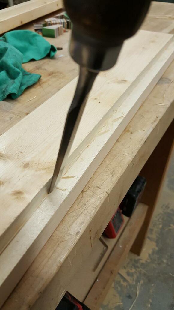
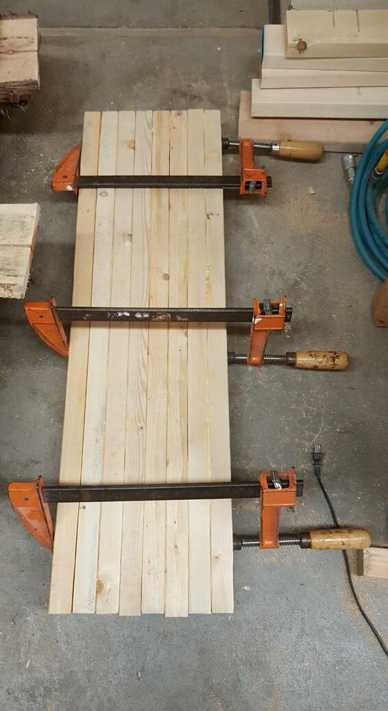
Testing/study Prototyping/fabrication
Problem:
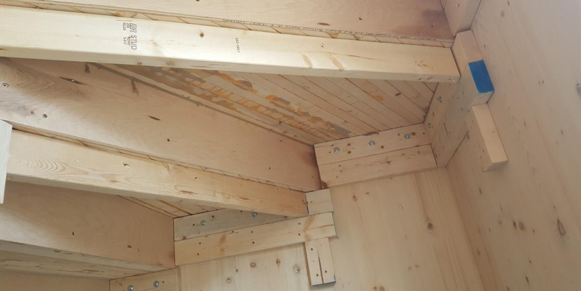
The width of the passage changes at many points due to the side walls not being perfectly parallel. This leaves the stairwell with different widths, not allowing all treads to be of same width.

00KtOT34dbnBFPeRpcTneq8m7xq.jpg
Solution:
All treads are fabricated 1.5” longer than the length of the first tread. These are later cut on site to the required dimension during installation.
Varying width of the stairwell
Problem:
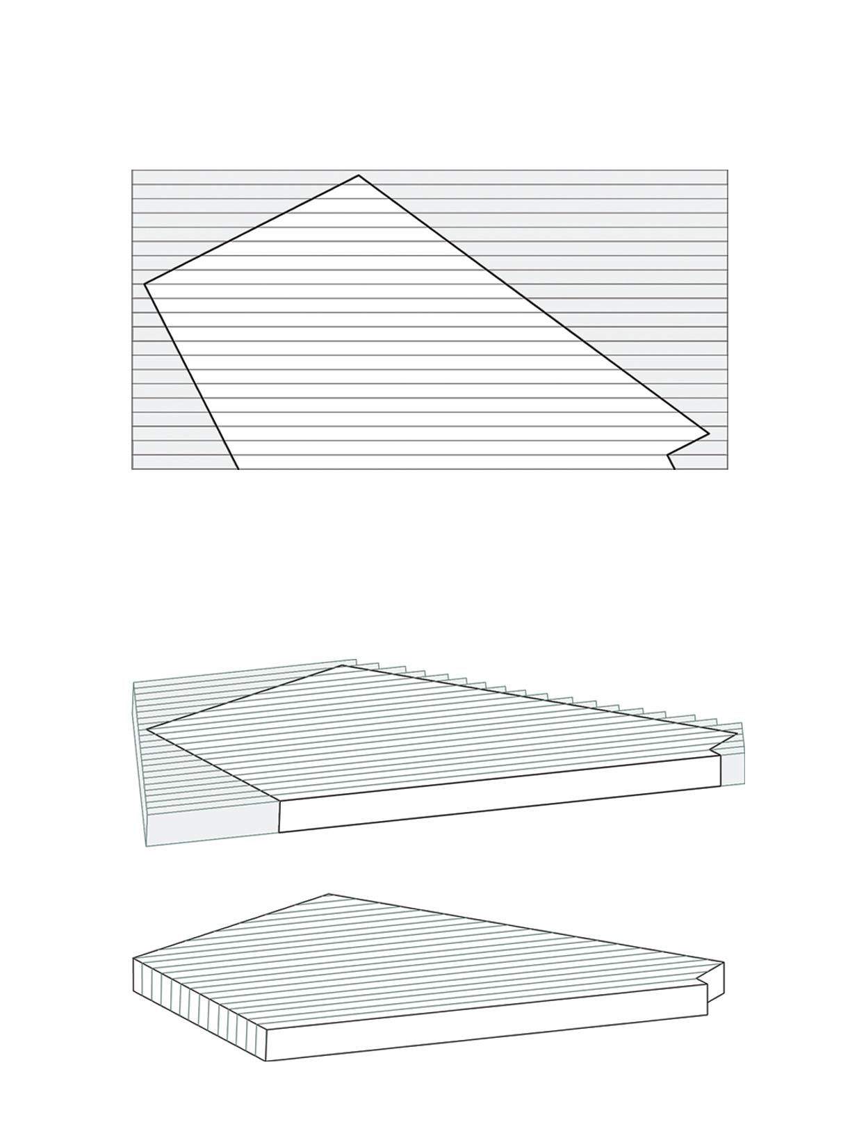
Winder treads which have angled edges waste a substantial amount of wood when cut out from the huge glue and dowel laminated rectangular piece.
https://mail.google.com/mail/u/1/#inbox/QgrcJHsBqLqLQwwzqLMQpmzkDlnlzQWJzKG?projector=1&messagePartId=0.1


Solution:
All the 2x4 wood pieces are cut to different lengths so when they are glue laminated, the staggered edge contains the angled edge within it, reducing the amount of wastage.
Winder tread- Material wastage
3/9/2019
1/1

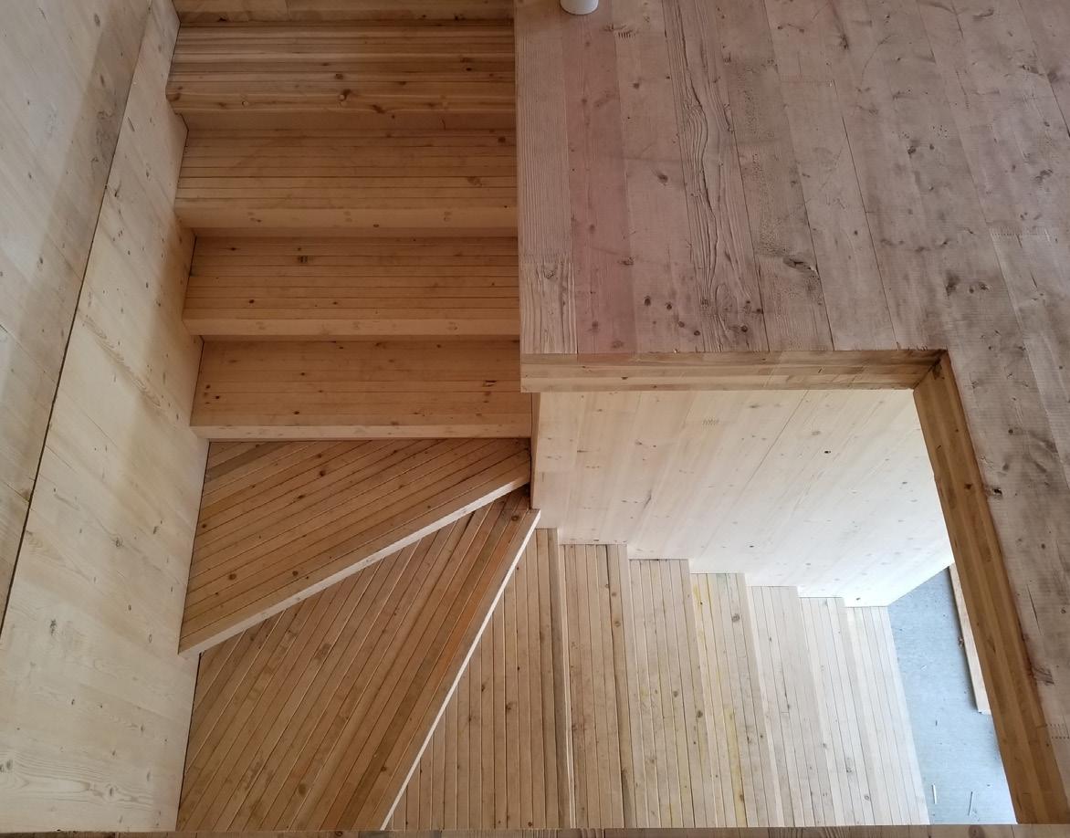


Installation process
The circular pieces are cut from a large sheet of 3/4” plywood by using the CNC. These are then sanded and glued in sets of four. Later these are stacked on site to form a column securing the pipe inside and allowing the handrail to be fixed upon.


13 4 " 4" 1 2 " 2" 2 1 8 " 1'-11 4 " 81 2 " 2 1 4 " 8" 41 4 " 21 4 " 65 8 " 8 7 16 " 1'-6 3 4 " 6" DN
Plan showing handrail and faux column Faux column fabrication and installation
Detail - handrail wrapping around the column
Glue-laminated
Metal brackets Faux column Pipe Steam bent
laminated
ash panels (3 nos)
and glue
ash strips


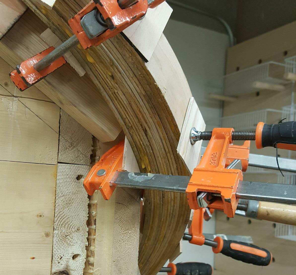
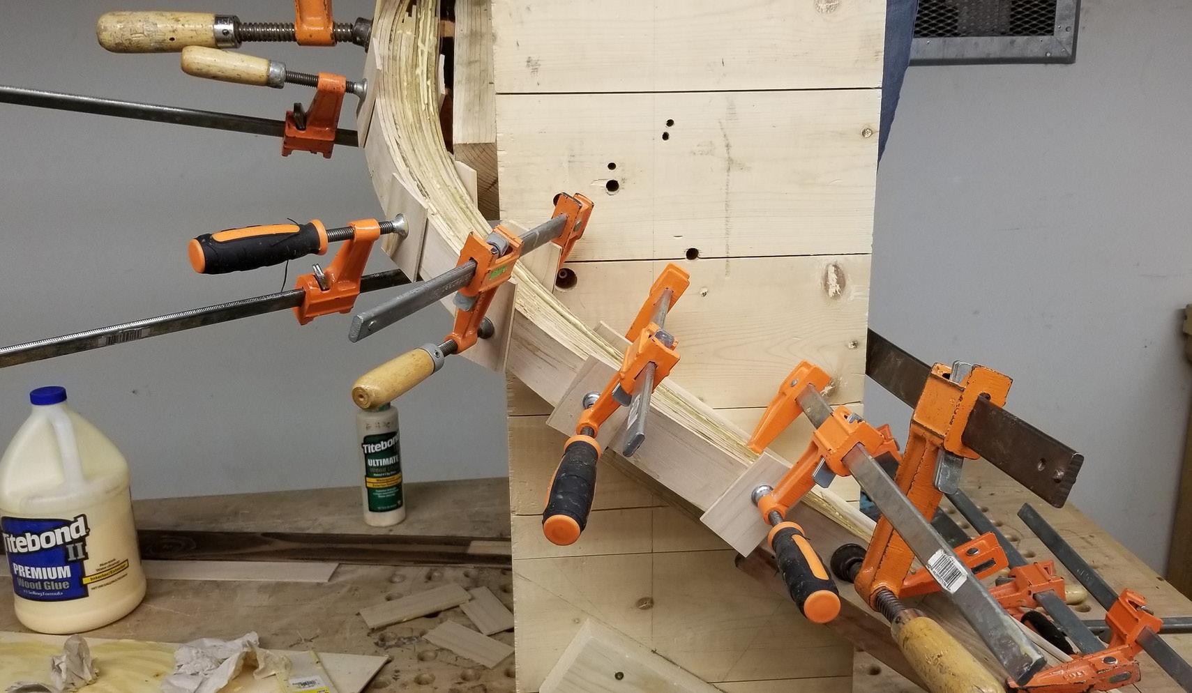
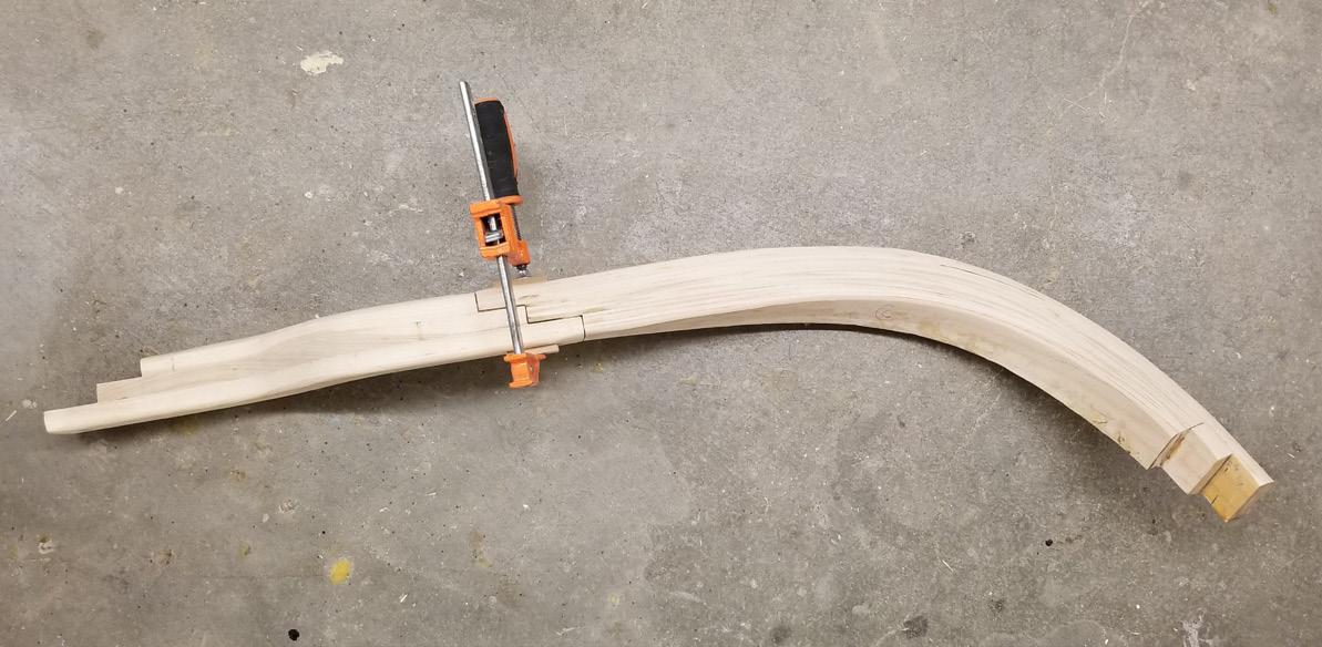
Steam bending and lamination - Doubly curved Steam bending and lamination - Singly curved
‘S’ shaped connecting pieces


2"
CNC cut Plywood pieces stacked and nailed with 6” long screws to form a faux column around the pipe which also allows the handrail to wrap around firmly
Ash strips steam bent and glue laminated to achieve the doubly bent curve across the corner forming a continuous snaky handrail with no sharp turns.


THE HIVE
Bee Research Facility
Grand Island, Nebraska
Studio - Spring 2018


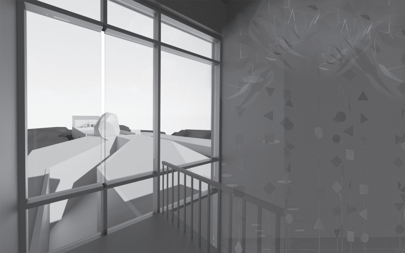
Architecture can directly have impact on the bees’ lifestyle based on the design which may either help them in performing all activities efficiently, or cause hindrance by manipulating the natural ways of performing their activities.
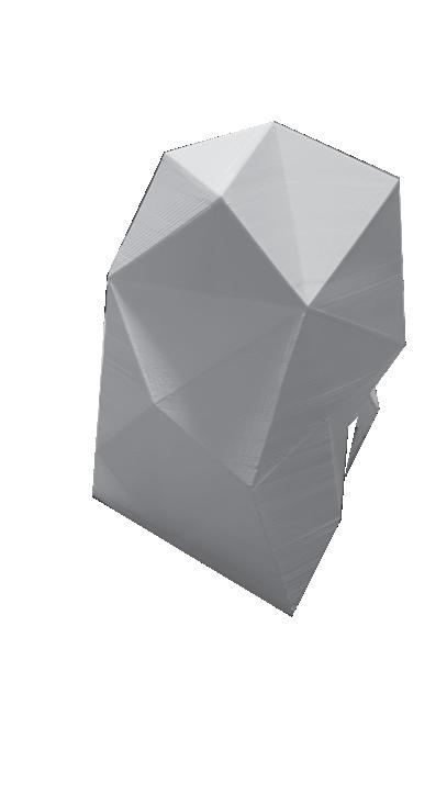
This project is a team work by two students with two major ideas married and blended together into the design. My design idea introduces user zone delineation while still intersecting them, providing a close peek into the hanging hives to witness a bees’ way of life and work.
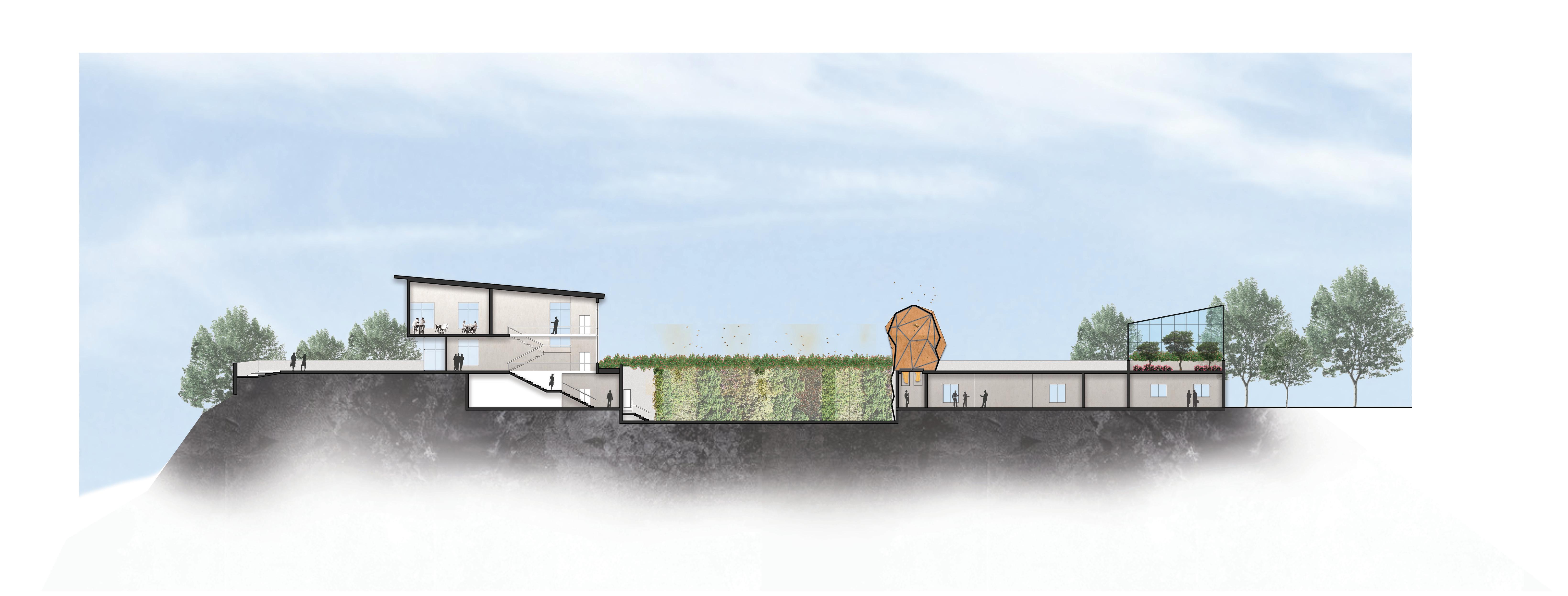
The purpose of this research center is to educate the visitors about bee keeping and its benefits. The design focuses on embracing the natural lifestyle of the bees. Hence, studies on their circulation patterns and activities led to designing a habitat where bees and human interaction can be carried out at various levels of adjacency. And, the design drives the way in which people experience learning by observing the activities closely without interfering.
02
Design idea
Crown at the peak


Levels of interaction with bees
Study model Sectional moment (study drawing)
Form development Zone delineation


Site Plan
Site entry/exit
Staff entry
Bee yard
Massing model
Entrance
Drawn by Andrew Hicks


UP UP To Service and Staff Parking DN UP A B C C A B A B C C A B
plan
level plan
Entrance level
Basement
11. Storage + service
12. Exhibit hall
13. Learning lab
14. Hive hallway
15. Honey extraction
16. Molecular lab
17. Hot room 18. Cold room
22.
1 3 2 4 7 6 10 9 8 7 11 12 13 6 14 15 21 18 17 19 11 16 20 22 4 9 5 N N
19. Wood shop 20. TV lounge 21. Fire exit
Staff entry
1. Entrance
2. Lobby
3. Retail
4. Restrooms
5. Deck
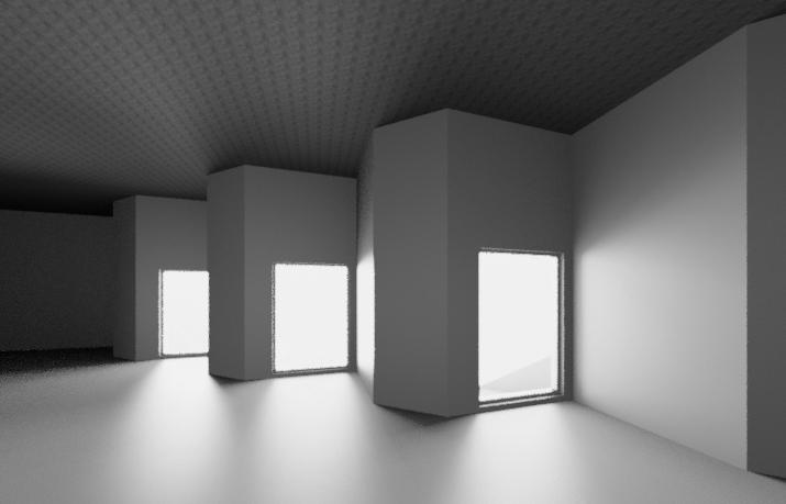
6. Light well
7. Roof garden
8. Hive
9. Bee yard
10. Green house
sheet metal parapet cap sloped to drain roof side; shim as required
concrete masonry unit sheet metal protection
pavers with shim
loose-laid retention tee
engineered soil
filter fabric
optional reservoir layer
moisture retention layer aeration layer
thermal insulation
drainage layer
root barrier protection course thermoplastic water proofing membrane
1' thick roof slab (hollow core) sealant, if required membrane flashing seam plates and fasteners
air, vapor /moisture barrier rigid insuation

2" Air cavity
1" thick precast concrete panels
continuous cleat
Section A
Green roof detail


Exhibition /display Basement floor soil 6" growing medium Green roof assembly Rigid insulation Air, vapor/moisture barrier Hollow core slab CMU wall floor slab Rigid insulation foundation Air, vapor/moisture barrier learning lab Exterior rigid insulation air, vapor /moisture barrier 2" air cavity 1" thick precast concrete panel CMU wall Green roof detail Section B
Wall sections showing assembly

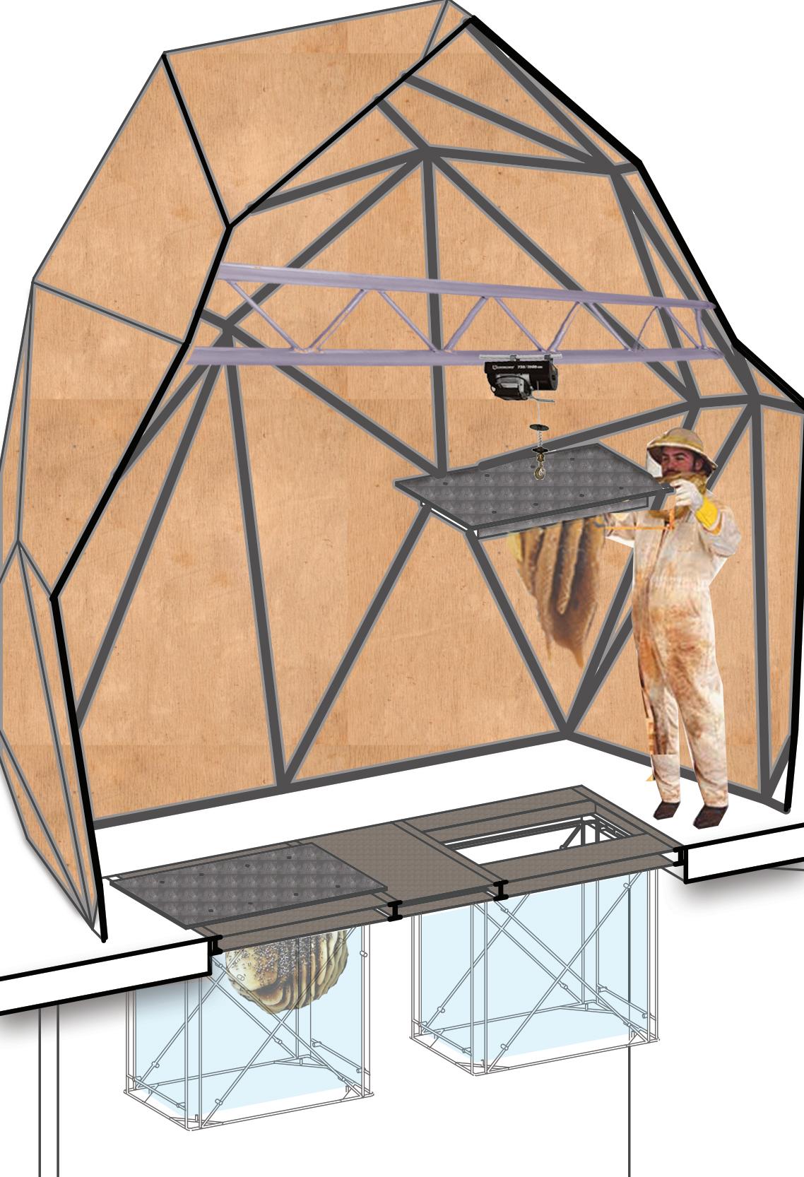


Access and maintenance of ‘The hive’ Section C


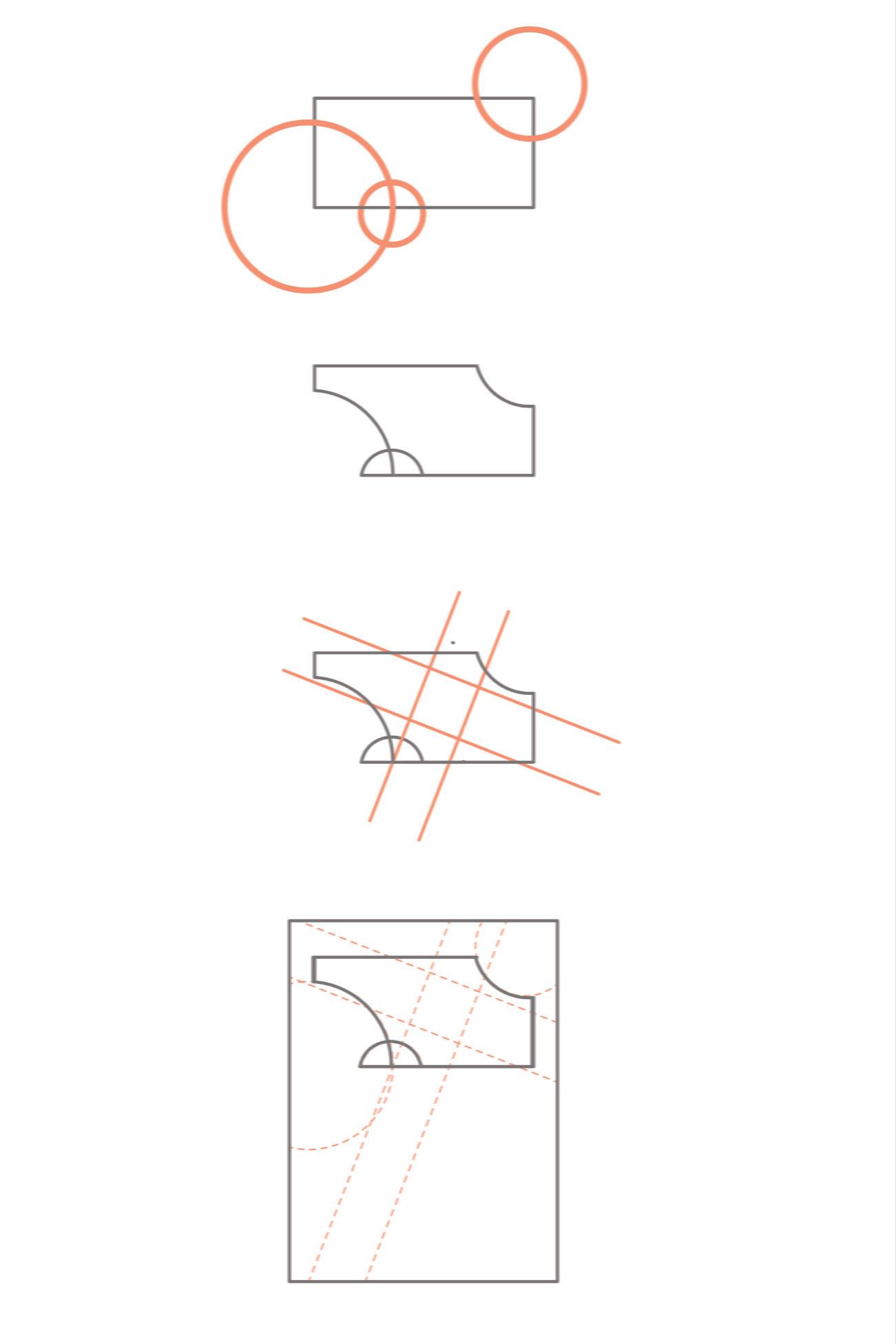
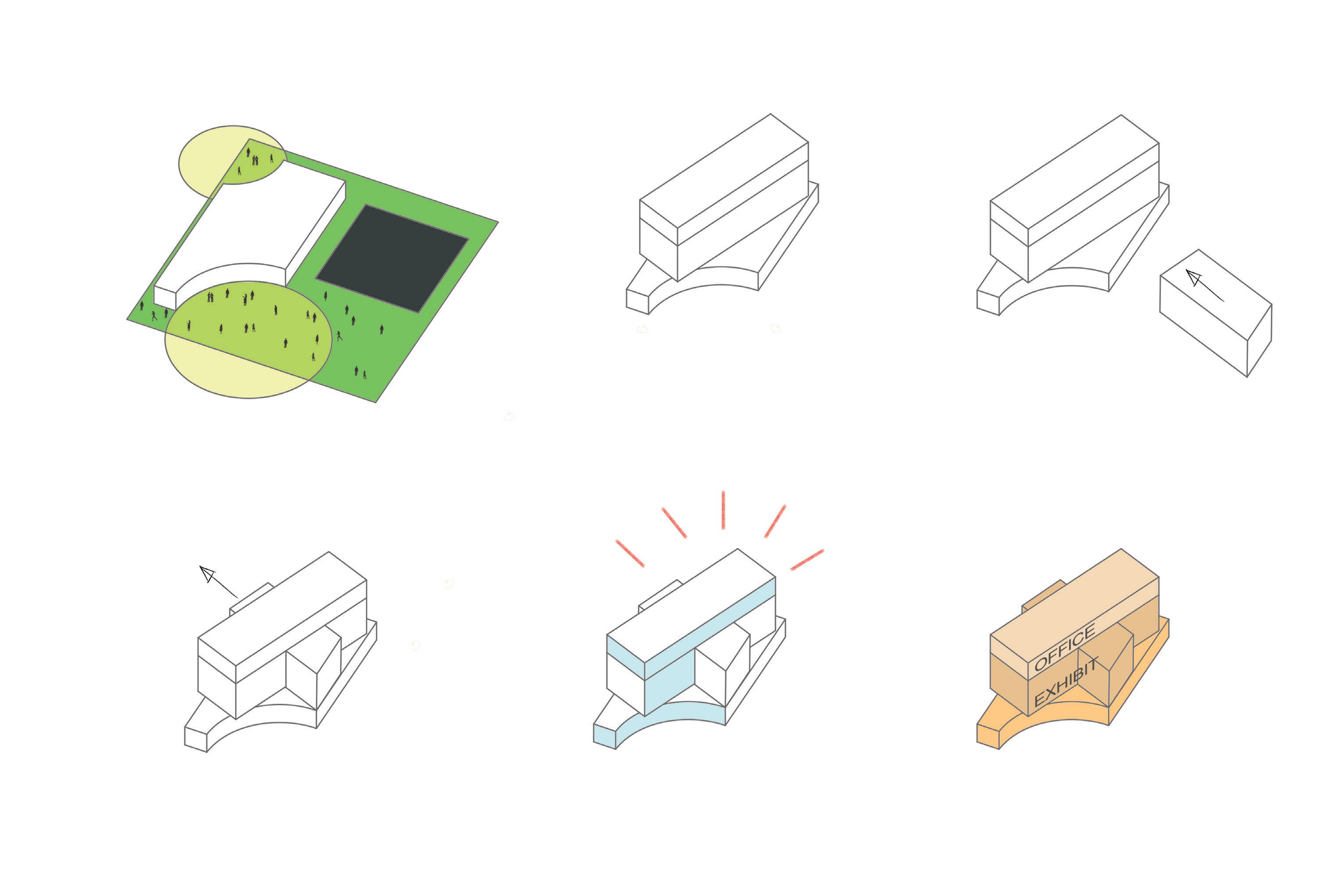
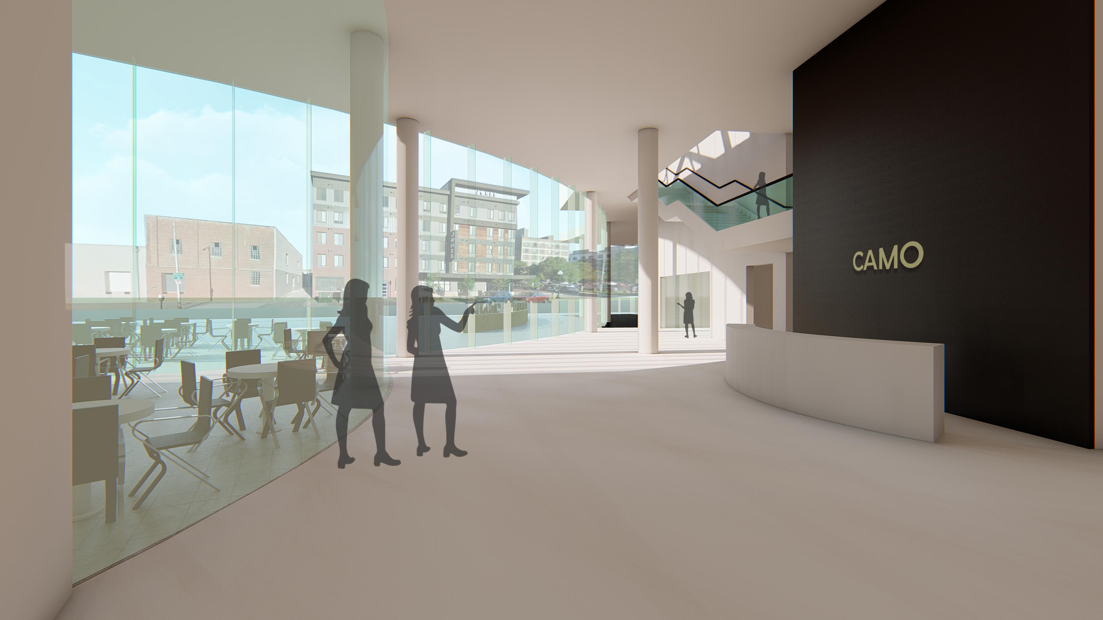
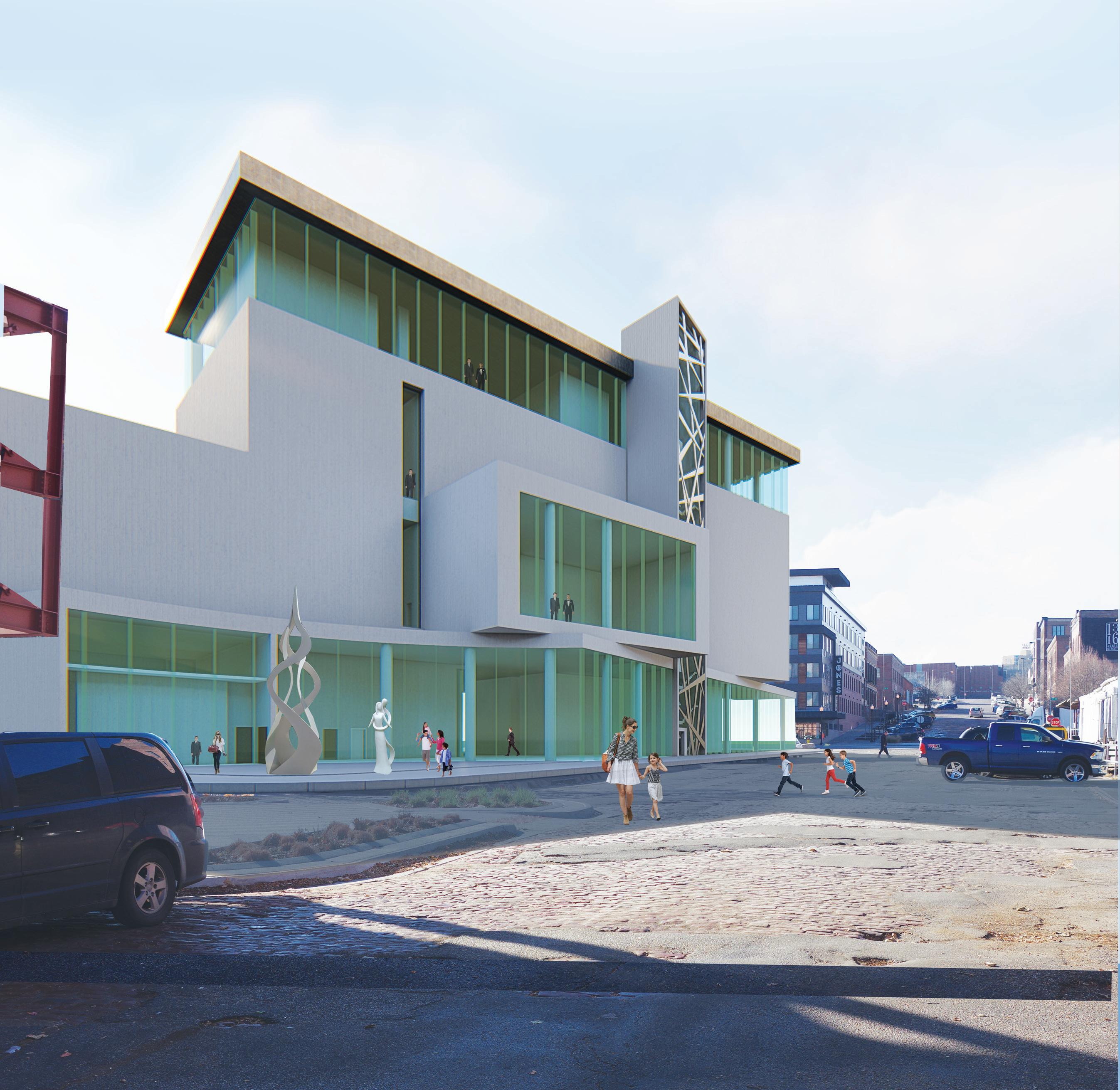
CAMO responds to the geometric character of the neighborhood in a dominant manner with its volumetric and monumental typology. It displays stacked masses of rectangular extrusions which intersect, creating a composition that informs the exterior form.
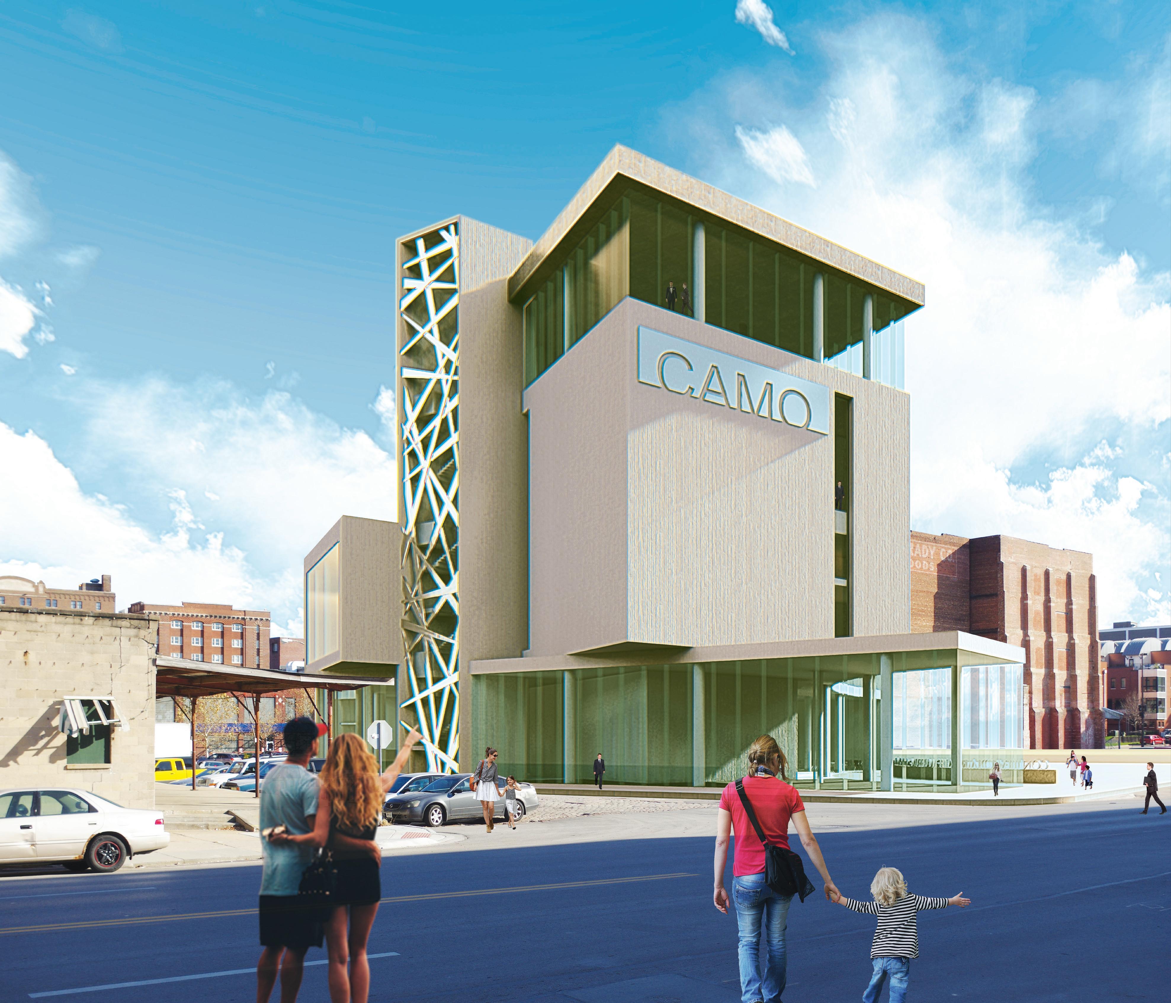
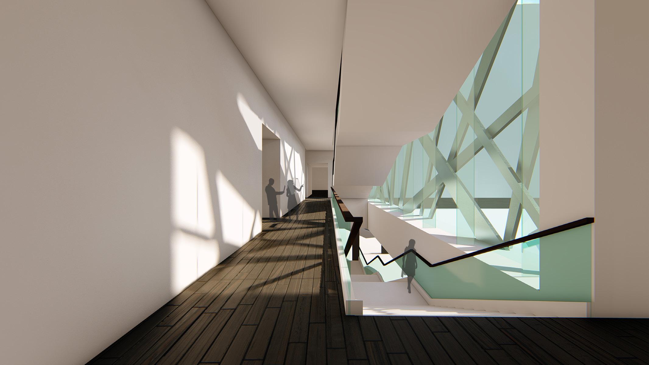
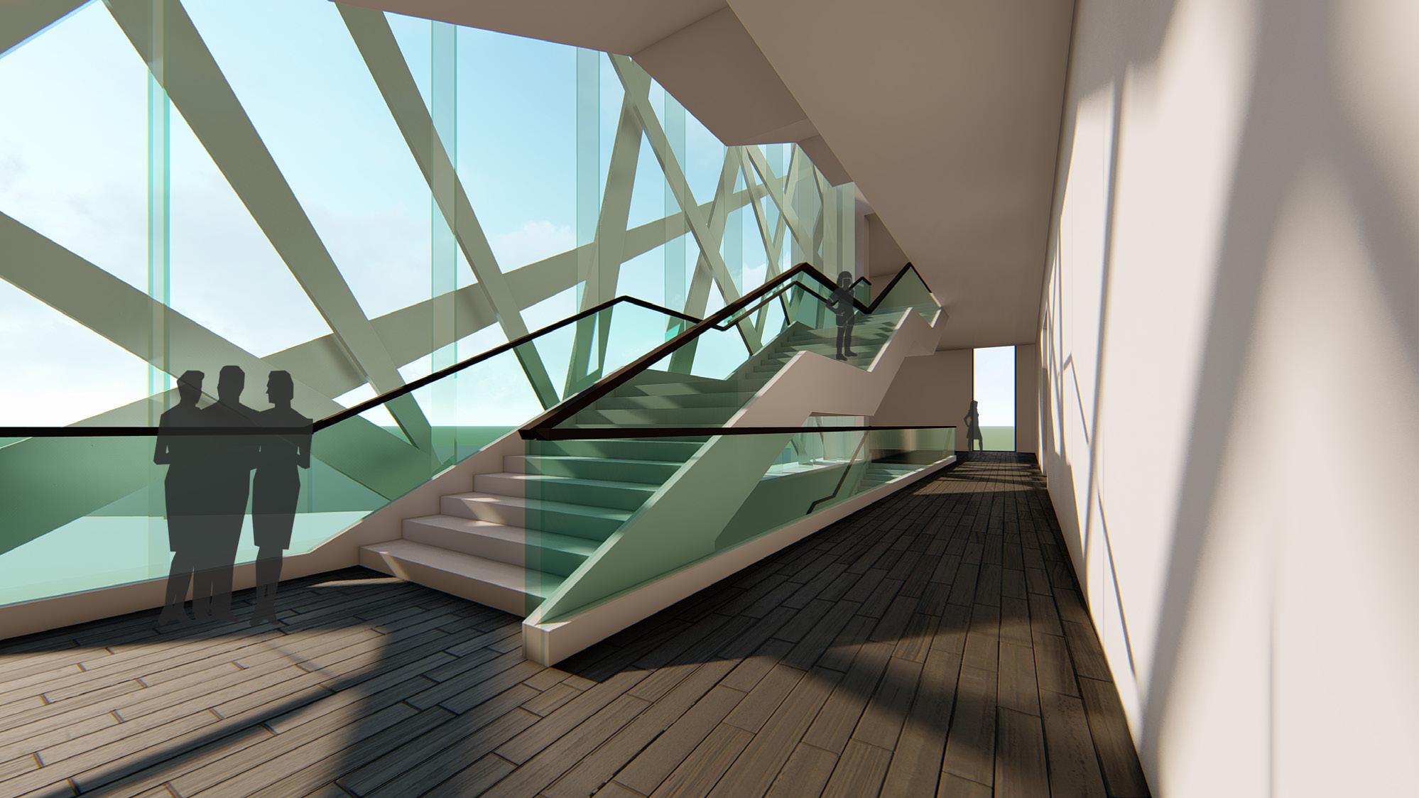
The site is designed with superimposing shapes to form interesting patterns along different axes creating a phenomenal transparency in the layout. The design focuses on the spatial qualities such as day light, transitional connectivity to other spaces, and volume.
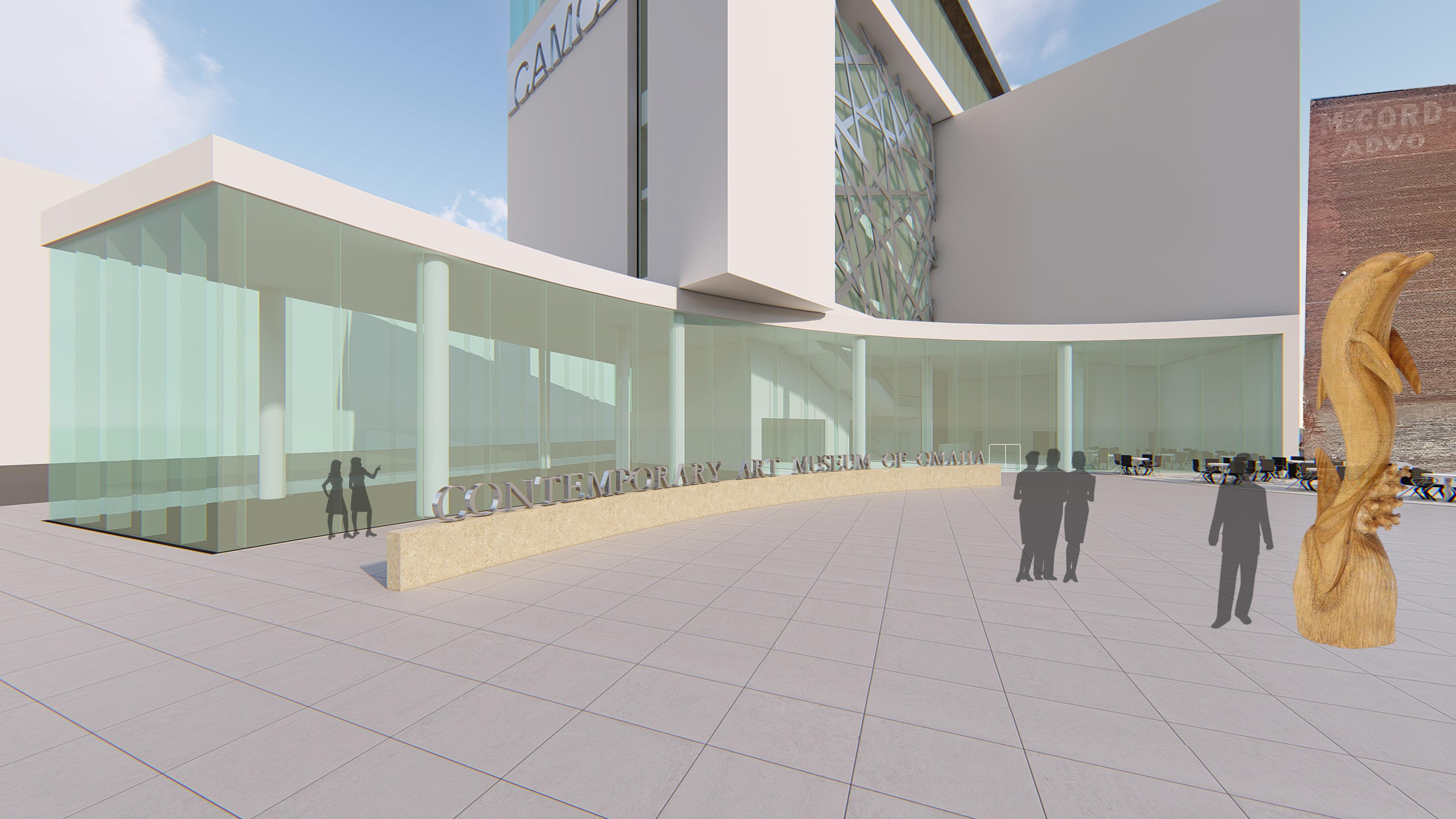
The promenade of the museum delights a visitor with its bright and generous transition spaces connecting them to the outdoor cityscape continuously as they progress through levels of the museum. With beautiful patterns formed by the sunlight entering in through the metal curtain wall, the vertical circulation across the huge glazing is an interesting space. A crown of glazing runs around the building forming the administration area with ample day light and generous views of the downtown.
03
2018
CONTEMPORARY ART MUSEUM OF OMAHA Omaha, Nebraska Studio - Fall



Jones Street Facade


Site plan Jones Street S 13th Street S 12th Street Leavenworth Street
SP B B A A SP A Ground floor plan
Sculpture garden / Plaza 2. Entrance 3. Lobby 4. Cafe 5. Outdoor seating 6. Gallery shop 7. Street level gallery 8. Members lounge 9. Library/archives 10. Pre-function 11. Auditorium 12. Kitchen 13. Security 14. Loading ramp 15. Side entrance 16. Gallery 1 17. Gallery 2 18. Gallery 3 19. Banquet hall 20. Student assembly 21. Classroom 1 22. Classroom 2 23. Art-lab 24. Crate storage 25. Restrooms 26. Service lift 1 2 3 4 5 6 7 8 25 10 15 11 9 13 12 14 26 16 SP Second floor
1.


SP B B A A SP SP B A
19 17 24 22 21 23 20 18 18 B N floor plan
Third floor plan

Section A

Section B
04 TRIPOD LAMINATED CHAIR


Product design
The tripod chair is designed for transition spaces especially those in a museum which connect major galleries. The purpose is to provide the visitors with a chance to take a quick break before transitioning into the next space of activity. When placed in spaces facing outdoor exhibits, gardens, fountains etc. , one can take a seat temporarily to relax and enjoy the outdoor views, before continuing their exploration of the next space.
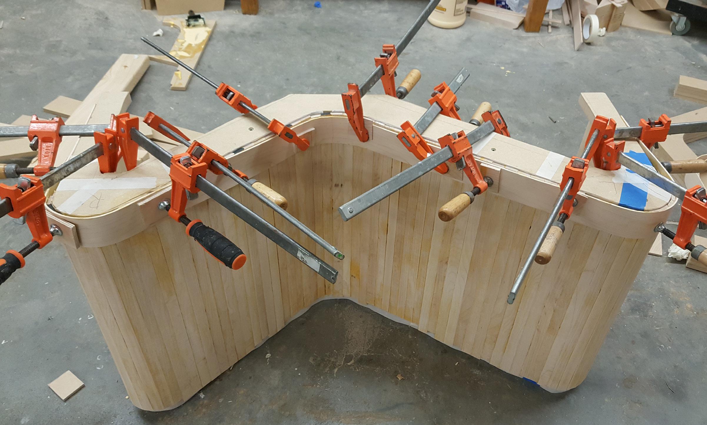
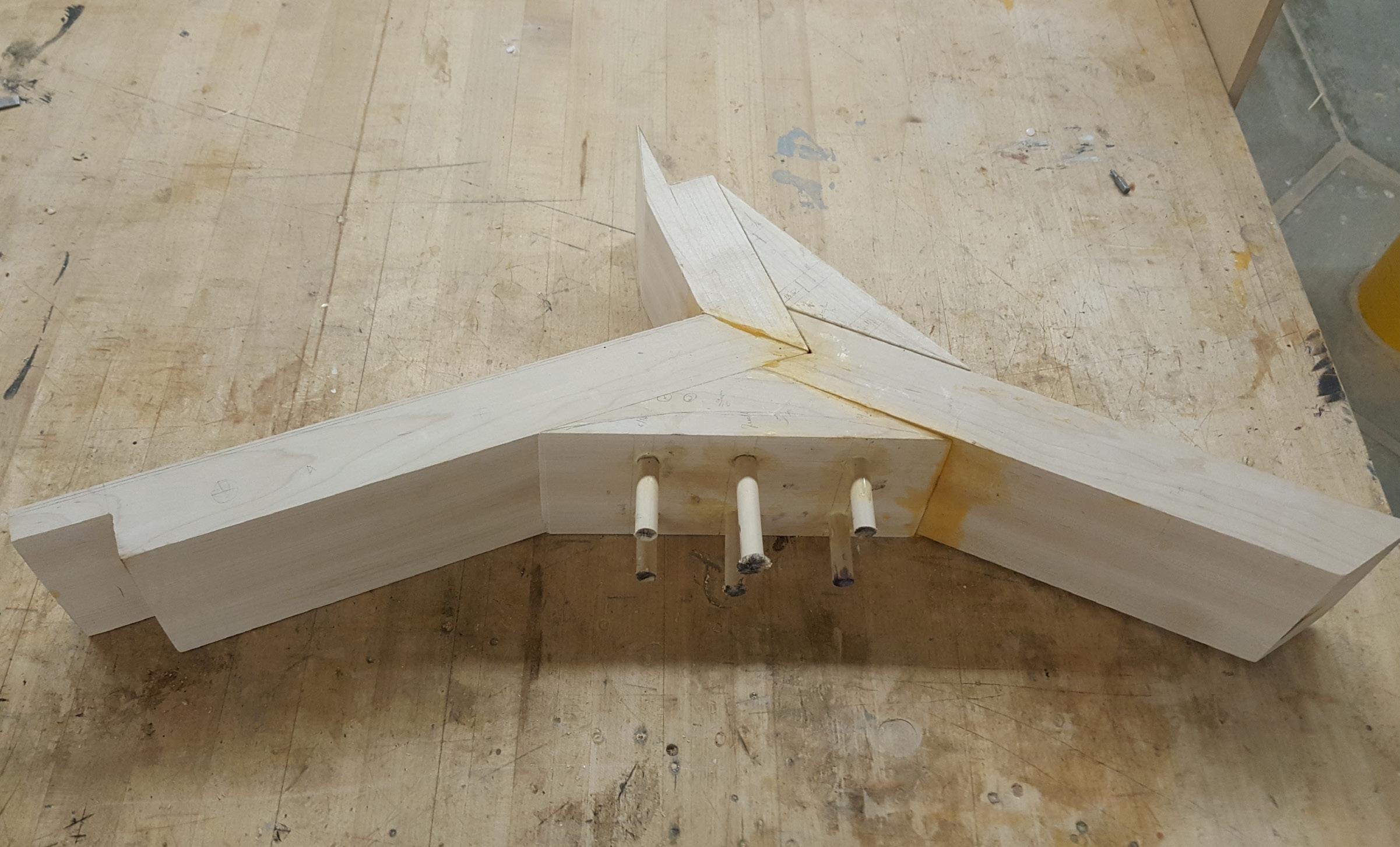
The chair uses maple wood for its aesthetically pleasing and light weight appearance. Challenges faced in designing and making of this chair are of critical dimensions and angles, and to be able to support a human comfortably on the tripod bottom. The design incorporates techniques such as steam bending, cross lamination, and the use of dowels for reinforcement. The tripod chair is inspired from Danish and Finnish furniture design styles.

 Studio - Fall 2018
The Paimio chair by Alvar Aalto
Steam bent furniture by Bar Gantz Inspiration
Mock-up



 Wood steaming set up
Jig for stacking seat layers
Steamed wooden strips bent and clamped
Layer 1-transverse
Cross lamination of seat layers on the jig


 Layer 2- longitudinal
Front legs
Layer 3- transverse
Center frame
Dowel reinforcement for center frame

 Dowel reinforcement
1. Glue-laminated front leg
2. Center frame assembly
3. Glue-laminated center frame
4. Front leg and center frame attachment
5. Seat attachment to leg frame
Dowel reinforcement
Dowel reinforcement
1. Glue-laminated front leg
2. Center frame assembly
3. Glue-laminated center frame
4. Front leg and center frame attachment
5. Seat attachment to leg frame
Layer 1: transverse wooden strips
Layer 2: longitudinal wooden strips, 2” wide
Layer 3: transverse wooden strips
Cross laminated timber (CLT) seat


Material: Maple
Glue laminated front legs and center frame
Material: Maple
1 2 3
PROFESSIONAL/ INTERNSHIP
FORD CONSERVATION CENTER
- MASONRY REPAIR PROJECT


Omaha, Nebraska ( Existing building )
The Ford Conservation Center in Omaha, Nebraska, built in 1995 is a historic building that suffers due to structural inability to control moisture transmission through exterior walls and ceiling. Constant damp surfaces were causing damage to masonry brick veneer and mortar joints. And, Efflorescence formed ugly white patches.
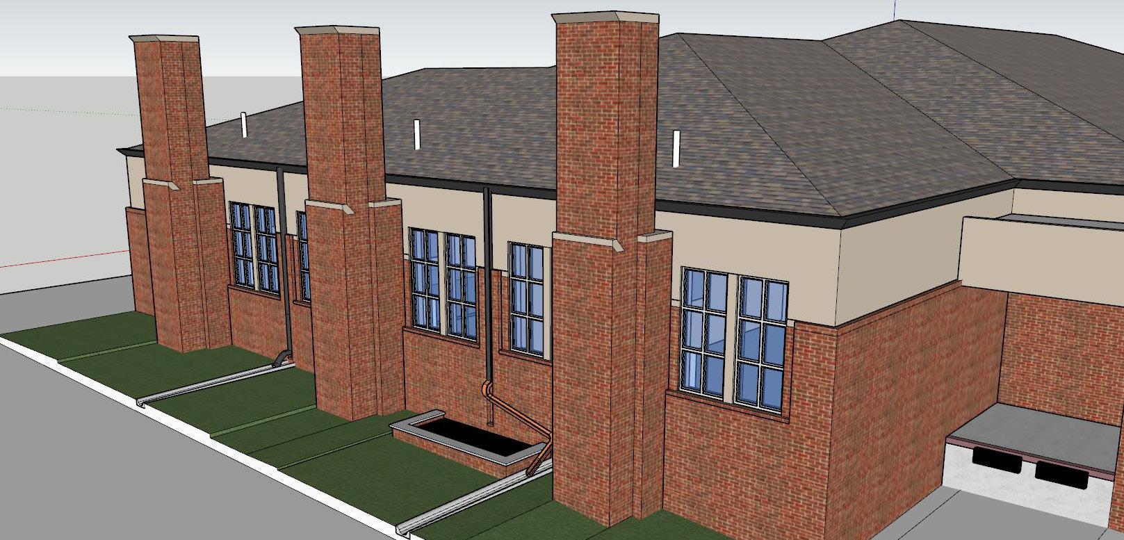
In an attempt to restore the structure, a maintenance plan was proposed. This included: 1) Removal of the 3 striking age old chimneys, 2)Relocation of the entire exhaust system that is within the chimneys, into the laboratories, and 3) Re-pointing the facade. This also involved research, and design support from the mechanical engineers to relocate the exhaust system.
Tasks accomplished:
1. Coordinated with mechanical engineer.
2. Produced construction drawing set.
3. Created 3D visuals for the maintenance proposal.
4. Researched on problematic areas causing moisture intrusion.
PROJECT HIGHLIGHTS

05
N
3) Removal of chimneys on North facade
1) Re-pointing exterior mortar joints
4) Re-location of exhaust fan
Exhaust fan
Re-locate inside labs
Chimneys to be removed
Objects lab Textile lab Paper lab
2) Replacement of damaged stone
Lab
Chimney



TASK 2: DOCUMENTATION OF PROBLEMATIC AREAS
TASK 1: 3D-VISUALS FOR RESTORATION PROPOSAL
Existing chimneys on North wall
New North wall post chimneys removal
Exhaust Fan relocation inside the laboratory

Documentation of existing interiors of the laboratories for providing base drawings to the mechanical team
Exhaust Fan within acoustic enclosure

SCALE: 1/8" = SECTION T.O.CHIMNEY FLR FIN. LOWER LVL W14x22 W14x22 W18x40 W14x22 W14x22 W12x14 W12x14 W12x14 W14x22 W14x22 W14x22 W18x40 W14x22 W18x40 W14x22 W14x22 W14x22 W14x22 L-6 L-5 L-5 L-5 L-5 L-6 W12x14 L-3 W24x55 W18x35 W24x62 L-1 L-3 W14x22 W18x40 W14x22 L-1 W14x22 L-3 W24x62 3" TYPE 'N' ROOF DECK 18 GA GALV 3" TYPE 'N' ROOF DECK 18 GA GALV 1'-8" 9'-0" 11'-0" 9'-0" 1'-8" 78'-0" 11'-10" 6'-2" 4'-10" 11'-0" 11'-0" 11'-10" 3'-10" 7'-2" 9'-0" 11'-0" 11'-0" 9'-0" 9'-0" 11'-0" 12'-0" 3'-8" 1'-0" 1'-0" 0'-10" 7'-2" 3'-10" 1'-0" 0'-10" TEXTILE LABORATORY 102 OBJECTS LABORATORY 101 PAPER LABORATORY 103 RECEIVING 142 N.VEST 143 CORRDOR 107 CORRIDOR 139 L-3 L-3 W14x22 L-1 W18x35 L-9 L-4 W14x22 W12x14 W12x14 W14x22 W14x22 W21x44 L-3 W12x14 L-3 W12x14 L-1 L-3 W18x35 L-1 W14x22 W14x22 W10x12 W10x12 C6x8.2 W14x22 L-4 W18x35 W14x22 W21x44 3'-43 8 5'-33 8 8'-7 7 8 SCALE: 1/16" = 1'-0" EXISTING FIRST FLOOR PLAN SCALE: 1/8" = 1'-0"
ENCLOSURE
SCALE: 1/2" = 1'-0" PLAN OF WEST ENTRANCE 1. OBJECTS LABORATORY 101 TEXTILE LABORATORY 102 PAPER LABORATORY 103 4 A-109 RECEIVING 142 N.VEST 143 CORRDOR 107 CORRIDOR 139 5'-11 5 8 " 7'-6" A-105 4 NEW FAN ENCLOSURE (TYP) REMOVE EXISTING CEILING GRID SYSTEM, ACOUSTIC PANELS, LIGHT FIXTURES, DIFFUSERS AND DETECTORS IN THIS AREA TO FACILITATE INSTALLATION OF NEW FAN ENCLOSURES AND STRUCTURAL SUPPORTS, REINSTALL FOLLOWING COMPLETION OF FAN ENCLOSURE WORK. SEE NOTE ABOVE SEE NOTE ABOVE TEXTILE LABORATORY 102 OBJECTS LABORATORY 101 PAPER LABORATORY 103 RECEIVING 142 N.VEST 143 CORRDOR 107 CORRIDOR 139
R.C.P SHOWING SELECTIVE DEMOLITION FOR FAN
4.
TASK 3: COORDINATION WITH MEP CONSULTANTS FOR MECHANICAL WORK
Exterior Facade Treatment:
The exterior mortar joints on all facades, Brick Veneer Control Joints (VCJ) and Through wall Control Joints (TCJ), are required to be re-pointed in order to restore the facade.
Chimney demolition and fan relocation:
The demolition of chimneys was proposed along with relocating the fan into the labs. This will introduce a new wall with high performance moisture and vapor barrier at the North facade post demolition. Additionally an acoustic enclosure must be designed to encompass the re-located mechanical system inside the labs, which would otherwise remain exposed, creating noise pollution inside the labs.
TASK 4: CONSTRUCTION DOCUMENTS
Downspout & Gutter Sizing Reports
Project Name: Ford Conservation Center, Omaha
Rainfall Intensity (in/hr): 7.4
Based on rainfall averages in Omaha, NEBRASKA (10 years)
Roof Rainfall Design Area (ft²): 16,286.50
* Area of Largest Roof Serving a Single Gutter System
Design Area manually entered by user
Gutter in Lineal Ft: 664
* Length at Largest Roof Serving a Single Gutter System
Gutter Length Serving Single DS (ft.): 37
*Assumption: downspouts are equally spaced
**Maximum gutter length to be served by a downspout is 50ft per SMACNA ASMM

M (depth to width ratio): 0.75
Min. Gutter Width (in.): 6 [Rectangular]

Min. Gutter Depth (in.): 4.5
# of Downspouts: 18
Additional Downspouts: 4
*to reduce size of gutter and downspouts additional downspouts can be added
Min. Area per DS (in²): 5.66
Min. DS Size (in): 3 [Plain Round]
*Per Table 1-3 on page 1.4 of SMACNA ASMM
Roof gutter inefficiency:
Research was performed to determine whether the existing roof gutter meets the size requirements as per the SMACNA gutter sizing based on the roof area and volume of the annual rainfall that Nebraska receives. This clearly showed the existing gutter was undersized, proving its inefficiency in rain water drainage, adding to the problem.
SCALE: 3/8" = 1'-0" SECTION SHOWING SELECTIVE DEMOLITION SPACE 5. SCALE: 3/8" = 1'-0" PLAN DETAIL 1. SCALE: 1 1/2" = 1'-0" HSS CONNECTIONS 3. SCALE: 3/4" = 1'-0" ENCLOSURE PLAN 4. FIN. FIRST LVL EL. = 100'- 0" T.O.CONC. FND EL. = 96'- 8" FIN. LOWER LVL EL. = 88'- 0" EXISTING EXHAUST FAN AND DUCT WORK TO BE REMOVED FOR RELOCATION (SEE MEP DWGS FOR RELOCATION OF EXHAUST SYSTEM) T.O.LIMESTONE EL. = 115'- 4" EXISTING GUTTER AND STONE FASCIA TO REMAIN (SEE NOTE 1) REMOVE EXISTING BATTERED BRICK MASONRY AND EXHAUST CHIMNEY EXISTING STEEL FRAME AND EXISTING MASONRY ABOVE THE FRAME TO REMAIN T.O.LIMESTONE EL. = 126'- 8" GRADE EL. = VARIES CONCRETE FOUNDATION WALL TO REMAIN (SEE PLAN DETAIL 1 ON THIS SHEET) EXISTING FUME HOOD 1'-0" SAW CUT AND REMOVE 12" WIDE FULL HEIGHT SECTION FROM FACE OF EXISTING C.I.P. CONCRETE WALL. REMOVE AND FILL WITH COMPACTED BACKFILL A-109 6 PREFABRICATED BY MECHANICAL 3/4" TREATED PLYWOOD CRICKET EXISTING ROOF 1/2" DIA THROUGH BOLT IN 2" HORIZ SLOT IN ANGLE PARALLEL TO TUBE L6x3 1/2x5/16x0'-6" LLH W/ (2) 1/2" DIA A325 FIELD DRILL EXIST BEAM FOR BOLT CONNECTION HSS 3 x 3 x 1/4 EXISTING BEAM W14 EXISTING BEAM W14 HSS 6 x 3 x 1/4 L6 x 3 1/2 x 5/16 x 0'-6" LLH EACH SIDE OF TUBE W/ (2) 1/2" DIA A325 FIELD DRILL EXIST BEAM FOR BOLT CONNECTION (2) 1/2" DIA THROUGH BOLT IN 2" HORIZ SLOT IN ANGLE PARALLEL TO TUBE 2'-6" 7'-6" 7" 2'-1" 3 A-110 4 7 8 4 7 8 1/2" DIA THREADED A-109 7 A-109 6 A-105 4 24" X 36" RECESSED ACOUSTICAL ACCESS DOOR BY BEST ACCESS DOORS SKU BA-ACD-2064-24-36 VCJ VCJ TCJ VCJ TOP OF PARAPET EL. = 115'-4" TOP OF COLUMN EL. = 108'- 8" BOTT OF LIMESTONE EL. = 110'- 8 3/8" TCJ VCJ VCJ VCJ VCJ TCJ TOP OF LIMESTONE EL. = 115'-4" TOP OF BRICK EL. = 111'- 1 3/8" FIN. FIRST LVL EL. = 100'- 0" TCJ VCJ VCJ TCJ VCJ TOP OF PARAPET EL. = 115'-4" TOP OF COLUMN EL. = 108'- 8" BOTT OF LIMESTONE EL. = 110'- 8 3/8" TCJ VCJ VCJ VCJ VCJ TOP OF LIMESTONE EL. = 115'-4" TOP OF BRICK EL. = 111'- 1 3/8" FIN. FIRST LVL EL. = 100'- 0"
TASK 5: RESEARCH ON ROOF GUTTER SIZING
16 OZ LEAD COATED COPPER COUNTER FLASHING
16 OZ LEAD COATED COPPER CRICKET FLASHING EXISTING ROOF DECK
GENERAL NOTES
1. EXISTING DOCUMENTATION INDICATE THE STONE PANELS ARE MOUNTED ON STEEL SUPPORT FRAMES. CONTRACTOR TO CAREFULLY REMOVE STRUCTURE BELOW THE STONE PANELS WHICH ARE INDICATED AS "TO REMAIN" TO CONFIRM EXISTENCE OF SUPPORT STRUCTURE. NOTIFY ARCHITECT IF PANELS ARE UNSUPPORTED
HSS 6x3x1/4" SPANNING BTW EXISTING ROOF BEAMS (SEE HSS CONNECTION DETAIL 3 ON THIS SHEET)
DRILL TUBES FOR THREADED RODS TO PASS THROUGH; PROVIDE NUT & WASHER @ T.O. TUBE-TYP
ACOUSTIC
HSS 3x3x1/4" SPANNING BTW EXISTING ROOF BEAMS (SEE HSS CONNECTION DETAIL 3 ON THIS SHEET)
MIN 6" EMBED
SHEET NUMBER: FORD CONSERVATION CENTER DATE: 03/02/2020 PROJECT NO.: 201920-920 FORREVIEWONLY NOTFOR CONSTRUCTION 1201 'O' Street Suite 302 Lincoln, NE 68508 402.475.0597 berggrenarchitects.com BERGGREN ARCHITECTS A-109 SPACE OF CHIMNEY SCALE: 3/8" = 1'-0" SECTION THROUGH ENCLOSURE AND NEW NORTH WALL 6. SCALE: 3/8" = 1'-0" SECTION THROUGH LAB WINDOW 7.
NOT TO SCALE CRICKET DETAIL 2. 1326 S 32nd ST, Omaha, NE 68105 FIN. FIRST LVL EL. = 100'- 0" GRADE EL. = VARIES FIN. LOWER LVL EL. = 88'- 0" EXISTING FUME HOOD IN ELEVATION NEWLY ADDED FACE BRICK IN ELEVATION FALSE CEILING EL. = FV ENCLOSURE IN ELEVATION EXISTING 2" RIGID INSULATION A-109 4 T.O.WINDOW SILL EL. = 105'- 4" HEAD OF WINDOW EL. = 113'- 4" FIN. FIRST LVL EL. = 100'- 0" 1 A-110 4 A-110 SEE MEP DWG NEW PIPE POSITION (SEE MEP DWG) EXISTING FUME HOOD NEW 12" CMU NEW FACE BRICK T.O.LIMESTONE EL. = 115'- 4" A-109 1 NEW LIMESTONE SILL T.O.ANGLE EL. = 114'- 10 7/8" A-109 4 CURB FOR EXHAUST PIPE WITH CRICKET (SEE CRICKET DETAIL) 9'-0" 7 3 8 6" 7'-6" 1/2" DIA THREADED STEEL ROD VIBRATION ISOLATOR 3'-0" 47 8 6" EXISTING CEILING 4" THK CONCRETE SLAB WITH METAL DECK, SUSPENDED FROM ROOF 6 A-110 1'-0" 6'-11 8 12" BOND BEAM W/ (2) #6 CONT; EPOXY INTO ADJACENT EXISTING CONSTRUCTION, MIN 6" EMBED 6" 18GA TRACK; FASTEN TO CMU W/ (2) 1/4"X 1 1/2 TAPCON @ 16" O.C. ACOUSTIC ENCLOSURE SIMPSON L50 FRAMING CLIP W/ (6) #10 SCREWS @ EA JOIST 12" BOND BEAM W/ (2) #6 CONT; EPOXY INTO ADJACENT EXISTING CONSTRUCTION,
ENCLOSURE PREFABRICATED CURB MECHANICAL PLYWOOD ROOF DECK
SCALE: 1/8" = 1'-0" SEALANT
2. SCALE: 1/8"
1'-0" SEALANT
ELEVATION 1. TCJ VCJ TCJ VCJ VCJ TCJ VCJ BOTT OF LIMESTONE EL. = 118'- 8 3/8" TOP OF PARAPET EL. = 115'-4" TOP OF BRICK EL. = 111'- 1 3/8" FIN. FIRST LVL EL. = 100'- 0" TOP OF FND WALL EL. = 99'- 0" TCJ TCJ TCJ TCJ VCJ VCJ VCJ TCJ VCJ VCJ VCJ TCJ VCJ VCJ TOP OF LIMESTONE EL. = 107'- 4" TCJ TCJ 5 A-105 SCALE: 1/8" = 1'-0" SEALANT JOINTS - EAST ELEVATION 2. SCALE: 1/8" = 1'-0" SEALANT JOINTS - WEST ELEVATION 1. TCJ VCJ TCJ VCJ VCJ TCJ VCJ BOTT OF LIMESTONE EL. = 118'- 8 3/8" TOP OF PARAPET EL. = 115'-4" TOP OF BRICK EL. = 111'- 1 3/8" FIN. FIRST LVL EL. = 100'- 0" TOP OF FND WALL EL. = 99'- 0" TCJ TCJ TCJ TCJ VCJ VCJ VCJ TCJ VCJ VCJ VCJ TCJ VCJ VCJ TOP OF LIMESTONE EL. = 107'- 4" TCJ TCJ 5 A-105
JOINTS - EAST ELEVATION
=
JOINTS - WEST
WAYNE COUNTY COURTHOUSE

- SURFACE GUTTER ADDITION Wayne, Nebraska ( Existing building )


Wayne County’s magnificent courthouse built in 1899, was facing several issues. Presented here is the resolution for one of the many concerns, the site grade. Over many years, the grade had risen around the courthouse causing the sandstone to deteriorate, presenting a desperate need for restoration.
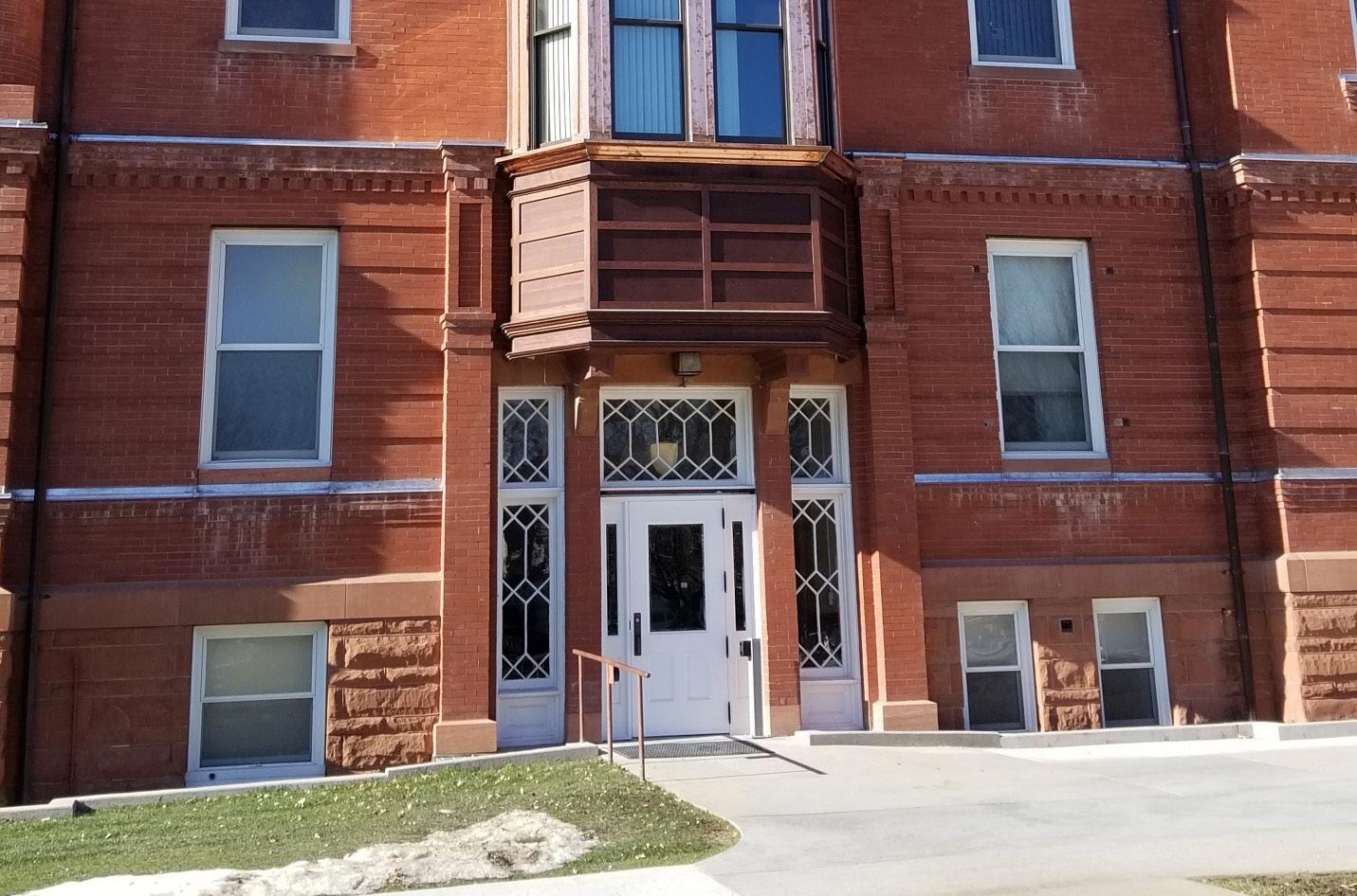
The challenge was to work with a firm budget of $2million set by the client for complete restoration work. Hence, work was done in stages and needed to be prioritized. As second most important scope of work, a perimeter gutter system around the courthouse was added to drain water away from the building and expose the first course of the rustic sandstone base water table. This saved the huge expense of regrading the site.

Tasks accomplished:
1. Produced construction detail drawings by translating sketches from the senior technical consultant.
2. Created 3D visuals to be included in the proposal and for better communication of design.

06
New surface gutter at the east entrance
N
Plan showing perimeter gutter addition
East entrance facade East
entrance
New surface gutter
New surface gutter
Existing Courthouse



1. SECTIONAL ELEVATION OF EAST SIDE GUTTER

4.
2. PART PLAN OF
- NORTH OF
3. DEMOLITION PLAN OF THE EXISTING CONDITION
SD-3 1 6" 1'-0" 8" 2"MAX 8" 8" 2" 6'-3" 6'-3" 8" SD-3 4 1'-6" 6'-3" 8" 201721-721 WAYNE CO. COURTHOUSE 13-09-2019 510 Pearl Street, Wayne, Nebraska 68787 Project number: Date: 1201 'O' Street Suite 302 Lincoln, NE 68508 PHONE: 402-475-0597 FAX: 402-475-5796 berggrenarchitects.com BERGGREN ARCHITECTS SCALE: 1/2" = 1'-0"
EAST SIDE GUTTER
EAST ENTRANCE SCALE: 1/2" = 1'-0"
ELEVATION OF EXISTING STEP TOP OF THE RAMP FRP GRATE (112" DEEP X 112" SQUARE MESH) ANCHORED TO THE SUPPORT INNER WALL OF THE GUTTER TOP OF FOUNDATION WALL WINDOW SILL FLOOR LINE OF THE GUTTER Exterior Restoration INNER WALL OF THE GUTTER EDGE OF RAMP EXISTING CONCRETE STOOP OUTER WALL OF THE GUTTER SD-3 RAMP SCALE: 1/2" = 1'-0"
2 1/2 x 2 1/2 x 1/4 STEEL ANGLE. 36" O.C. HOT DIP GALVANIZE AFTER FABRICATION, ANCHOR TO GUTTER WALL W/ 2 - 3/8 "Ø S/S EXPANSION BOLTS REMOVE PORTION OF EXISTING STEP FOR GUTTER CONSTRUCTION COPPER FLASHING PORTION OF EXISTING STEP TO BE DEMOLISHED PORTION OF EXISTING GUTTER WALL TO BE DEMOLISHED FOR EXTENSION OF THE GUTTER TILL THE EDGE OF THE RAMP EDGE OF RAMP RAMP FRP GRATE (112" DEEP X 112" SQUARE MESH) ANCHORED TO THE SUPPORT REMOVE PORTION OF EXISTING STEP FOR GUTTER CONSTRUCTION 8" SCALE: 1" = 1'-0"
FLASHING DETAIL FLASHING EXTENDS MIN 4" BELOW THE SLAB SEALANT 1 2" EXPANSION PAD CONCRETE SLAB 4" MIN EXISTING SPLIT FACE SANDSTONE WALL 30# FELT BOND BREAKER #4'S CONTINUOUS EXISTING FOUNDATION WALL CONTINUOUS REGLET IN EXISTING MORTAR JOINT 1 1 2" DEEP, SECURE WITH LEAD SCROLL & SEALANT EXTEND CONCRETE 6" ABOVE ADJACENT CONCRETE PAVING DRAIN OUTLET FROM PVC PIPE BENEATH STEPS #3'S @ 12" O.C. EXPANSION PAD AND SEALANT SAWCUT AND REMOVE EXISTING CONCRETE SLAB AS REQUIRED FOR GUTTER CONSTRUCTION. DOWEL INTO EXISTING SLAB W/ 1 2 " BAR 36" O.C 16 OZ COPPER FLASHING 2 1 2 x 2 1 2 x 1 4 STEEL ANGLE. 36" O.C. HOT DIP GALVANIZE AFTER FABRICATION, ANCHOR TO GUTTER WALL W/ 2 - 3 8 "Ø S/S EXPANSION BOLTS 20 OZ ANCHOR CONTINUOUS FRP GRATE (GRAY) ANCHOR TO SUPPORT 3-C. SCALE: 1 1/2" = 1'-0" DETAIL @ EAST GUTTER - NORTH OF EAST ENTRANCE 201721-721 WAYNE CO. COURTHOUSE 08-29-2019 510 Pearl Street, Wayne, Nebraska 68787 Project number: Date: 1201 'O' Street Suite 302 Lincoln, NE 68508 PHONE: 402-475-0597 FAX: 402-475-5796 berggrenarchitects.com BERGGREN ARCHITECTS Exterior Restoration 2" MAX SD-1 1'-0" 6" 8" ELEVATION VARIES, SLOPE TO DRAIN 1 8"/FT. 9 G-301 G-301 10 6" 1 1 2 2 1 2 " 2" Transferring concept sketches into construction details
spaces, material selection, producing detailed drawings of custom window joinery and bar counter design. Additionally I was assigned the task of preparing presentation boards in Photoshop to create rendered 2d drawings for presentation of design to the client.

F @ SB18 SB19 SB12 300 850 536 750 OUTDOOR UNIT OUTDOOR UNIT OUTDOOR UNIT FL SB11 SPLIT A/C GYP CEILING @ 3000MM HT GYP CEILING @ 2850MM HT. A/C PS3 PS1 VENEER CEILING @ 2700MM HT. 600 100 2400 100 600 1133 355 100 3750 100 200 100 SB11a 1530 2020 600 750 630 750 750 1380 1380 700 1000 800 1000 100 150 SPLIT A/C 1100 800 150 SB14 PS5 PS5 PS5 SB15 PS5 GYP CEILING @ 2850MM HT. GYP CEILING @ 2850MM HT. 1046 150 150 150 PS7 PS7 SB13 PS5 PS7a PS7a 450 750 SB17 G SPLIT A/C GYP CEILING @ 3000MM HT. SB16a SB16 A/C PS2 TV SB16b PS1 MC 162 SB17b SB17a 1200 1200 765 1000 150 350 350 150 Outdoor Dining hall Kitchen Son’s bedroom Servant’s room Wash area Pooja

SPLIT A/C GYP CEILING @ 2950MM HT. (AS PER SITE CONDITION) FL FL 2150 2150 750 750 G 975 OUTDOOR UNIT OUTDOOR UNIT FOYER 2700 2350 1490 SB9 SB10 SB8 DB DB PS1 200 1311 1026 550 200 450 900 SB4 SB5 PS1 SPLIT A/C A/C SB7 PS2a PS1 PS1 SB2 VENEER CEILING @ 2650MM HT. GYP CEILING @ 3000MM HT. GYP CEILING @ 2850MM HT. SB2a 750 1050 1050 1050 2840 750 1815 800 800 750 750 SB1 750 600 PS1 TV 1465 TV 1575 165 1475 700 700 965 1910 1650 1980 200 600 600 1370 550 588 SB6 A/C PS2 PS1 MC SB3 SB6a SB6b GYP CEILING @ 2950MM HT. GYP CEILING @ 2700MM HT. TV FORMAL LIVING + COURTYARD + DECK FFL 1050 [SB7+ TV] FFL 1050 [SB8] FFL [PS1] FFL [PS2a] 415 300 -1 NO. 5 AMPS SOCKET WITH SWITCH SB7 -1 FAN CONTROL SWITCH WITH REGULATOR PS2a PS1 300 mm 415 mm -4 NOS. 5 AMPS SOCKET WITH SWITCH -1 TV POINT -1 SPEAKER POINT TV.PT SP.PT 1050 mm TV -2 CEILING LIGHTS -2 CEILING LIGHTS -1 CEILING COVE LIGHT -1 CEILING COVE LIGHT -3 SPOT LIGHTS SB8 1050 mm -2 OUTDOOR WALL LIGHTS -1 LANDSCAPE LIGHTS S.LED -2 SPOT LIGHTS -2 CEILING LIGHTS (two way) -1 CEILING LIGHT(two way) 1050 mm -1 MASTER CONTROL SWITCH FOR TV TV TV F NORTH W E S GYP CEILING @ 2950MM HT. (AS PER SITE CONDITION) SB18 SB19 ONE-WAY CONNECTION TWO-WAY CONNECTION SB12 300 850 536 750 OUTDOOR UNIT OUTDOOR UNIT OUTDOOR UNIT SB9 SB10 FL SB8 DB DB PS1 SB11 SPLIT A/C GYP CEILING @ 3000MM HT GYP CEILING @ 2850MM HT. A/C PS3 PS1 VENEER CEILING @ 2700MM HT. 600 100 2400 100 600 1133 355 100 3750 100 200 100 SB11a 1530 2020 600 750 630 750 750 1380 1380 700 1000 800 1000 100 150 SPLIT A/C 1100 800 150 SB14 PS5 PS5 PS5 SB15 PS5 GYP CEILING @ 2850MM HT. GYP CEILING @ 2850MM HT. 1046 150 150 150 PS7 PS7 SB13 PS5 PS7a PS7a 450 750 SB17 G SPLIT A/C GYP CEILING @ 3000MM HT. GYP CEILING @ 2850MM HT. SB16a SB16 A/C PS2 TV SB16b PS1 MC 162 SB17b SB17a 1200 1200 765 1000 150 350 350 1050 800 750 600 150 Ground Floor Plan Entrance Living room Foyer Outdoor Garden Guest bedroom Garden Powder room Ground Floor Electrical Plan
BAR ENTERTAINMENT SD SD4 115 FG3 450 1200 ROOM 750 450 1050 A D B C 600 1718 600 450 1820 250 600 1500 600 100 3000 300 40 50 150 60 600 300 40 CEILING @ 2700 MM HT. VENEER CEILING @ 2700 MM HT. GYP CEILING PTD TO WHITE @ 2750 MM HT. GYP CEILING @ 2850 MM HT. OUTDOOR UNIT TO TERRACE BAR FG3 SD GYP CEILING @ 2750 MM HT. GYP CEILING PTD TO WHITE @ 2850 MM HT. GYP CEILING PTD TO WHITE @ 2850 MM HT. WOOD GRAIN VENEER CEILING @ 2700 MM HT. WOODEN STIPPED CEILING @ 2700 MM HT. 600 250 250 250 250 600 MC A/C PS2A TV S.LED S.LED PS5 450 150 150 600 450 150 600 150 450 150 150 600 150 600 450 150 150 600 1420 1785 500 645 1455 1450 450 1905 645 150 150 450 150 900 600 500 645 150 1905 450 1450 150 1455 450 645 GYP CEILING @ 2750 MM HT FROM FFL GYP CEILING @ 2850 MM HT FROM FFL VENEER CEILING @ 2700 MM HT FROM FFL 2700 VINYL FINISHED WALL 600 600 100 MM HT PRE LAM WOODEN SKIRTING DUMMY BOXING FINISHED WITH LEATHER PANELS 600 478 378 300 300 MM DEEP NICHES FINISHED WITH WHITE LAQUERED GLASS BACKING AND WHITE LACQUERED PAINT FINISH ON ALL SIDES GYP CEILING @ 2850 MM HT FROM FFL WOODEN STRIPPED CEILING @ 2700 MM HT FROM FFL VENEER CEILING @ 2700 MM HT FROM FFL VOIDS WITH WALL PAPER ON WALL WODDEN STRIPPED WALL SD 1050 1403 WODDEN STRIPPED SLIDING DOOR 1050 2700 BLACK GRANITE (LEATHERITE FINISH) JAMB DUMMY WALL FINISHED WITH SILKEN FINISH GRANITE 100 780 450 450 900 300 600 450 780 790 300 450 300 600 450 780 450 293 600 300 450 300 MM DEEP NICHES FINISHED WITH GREY LAQUERED GLASS BACKING AND GREY LACQUERED PAINT FINISH ON ALL SIDES 3083 102 MC 2700 54" LCD GYP CEILING @ 2850 MM HT FROM FFL WOODEN STRIPPED CEILING @ 2700 MM HT FROM FFL VENEER CEILING @ 2700 MM HT FROM FFL BLACK TINTED GLASS CENTER SHUTTER WALL PAPER AS PER ARCHITECT'S SELECTION 300 MM DEEP CABINET WITH WHITE HANEX TOP AND WHITE LACQUERED PAINT FINISH ON ALL SIDES WHITE LAQUERED PAINT FINISHED SHUTTERS BLACK LACQUERED GLASS PANELS ON WALL 20 MM THK BLACK GRANITE (LEATHERITE FINISH) WINDOW JAMB 100 MM HT PRE LAM WOODEN SKIRTING 350 1000 1000 1000 4273 900 WHITE HANEX TOP TURNS BACK AS WALL CLADDING FOR 150 MM HT. 50 50 150 1200 150 300 200MM DEEP,40 MM THK LEDGE FINISHED WITH WHITE HANEX TV 200 750 1080 50 450 2700 1250 1250 450 450 450 242 600 1500 GYP CEILING @ 2850 MM HT FROM FFL VENEER CEILING @ 2700 MM HT FROM FFL BLACK GRANITE(LEATHERITE FINISH ) CLADDING ON WALL 300 MM DEEP NICHE FINISHED WITH WHITE LAQUERED PAINT FINISH BACKING AND BLACK LACQUERED PAINT FINISH ON ALL SIDES 450 MM DEEP SUSPENDED CABINETWITH WHITE LAQUERED PAINT FINISHED SHUTTERS AND DRAWERS 2500 2468 BLACK GRANITE (LEATHERITE FINISH) DOOR JAMB WALL PAPER AS PER ARCHITECT'S SELECTION 600 617 eq 40 MM THK WHITE HANEX TOP TURNS BACK FOR 150MM HT AS WALL CLADDING 100 1200 450 450 668 450 450 300 eq eq RIBBED SHUTTERS PAINTED TO COLOUR 100 MM HT PRE LAM WOODEN SKIRTING 250 450 250 450 250 250 RIBBED SHUTTERS PAINTED TO COLOUR ELEVATION - A ENTERTAINMENT ROOM ELEVATION - C ENTERTAINMENT ROOM ELEVATION - B ENTERTAINMENT ROOM ELEVATION - D ENTERTAINMENT ROOM FALSE CEILING LAYOUT ENTERTAINMENT ROOM FURNITURE PLAN ENTERTAINMENT ROOM 1050 1200 750 450 A D B C 40 50 150 60 300 VENEER CEILING @ 2700 MM HT. GYP CEILING @ 2850 MM HT. OUTDOOR UNIT TO TERRACE GYP CEILING @ 2750 MM HT. 600 250 250 250 600 A/C PS2A TV S.LED S.LED S.LED S.LED 450 150 150 600 450 150 600 150 450 150 150 600 150 600 450 150 150 600 500 645 1455 1450 450 1905 645 150 150 450 150 900 600 500 GYP CEILING @ 2750 MM HT FROM FFL GYP CEILING @ 2850 MM HT FROM FFL VENEER CEILING @ 2700 MM HT FROM FFL 2700 VINYL FINISHED WALL 600 600 100 MM HT PRE LAM WOODEN SKIRTING DUMMY BOXING FINISHED WITH LEATHER PANELS 600 478 378 300 300 MM DEEP NICHES FINISHED WITH WHITE LAQUERED GLASS BACKING AND WHITE LACQUERED PAINT FINISH ON ALL SIDES GYP CEILING @ 2850 MM HT FROM FFL WOODEN STRIPPED CEILING @ 2700 MM HT FROM FFL VENEER CEILING @ 2700 MM HT FROM FFL VOIDS WITH WALL PAPER ON WALL WODDEN STRIPPED WALL SD 1050 1403 WODDEN STRIPPED SLIDING DOOR 1050 2700 BLACK GRANITE (LEATHERITE FINISH) JAMB DUMMY WALL FINISHED WITH SILKEN FINISH GRANITE 100 780 450 450 900 300 600 450 780 790 300 450 300 600 450 780 450 293 600 300 450 300 MM DEEP NICHES FINISHED WITH GREY LAQUERED GLASS BACKING AND GREY LACQUERED PAINT FINISH ON ALL SIDES 3083 102 MC 2700 54" LCD GYP CEILING @ 2850 MM HT FROM FFL WOODEN STRIPPED CEILING @ 2700 MM HT FROM FFL VENEER CEILING @ 2700 MM HT FROM FFL BLACK TINTED GLASS CENTER SHUTTER WALL PAPER AS PER ARCHITECT'S SELECTION 300 MM DEEP CABINET WITH WHITE HANEX TOP AND WHITE LACQUERED PAINT FINISH ON ALL SIDES WHITE LAQUERED PAINT FINISHED SHUTTERS BLACK LACQUERED GLASS PANELS ON WALL 20 MM THK BLACK GRANITE (LEATHERITE FINISH) WINDOW JAMB 100 MM HT PRE LAM WOODEN SKIRTING 350 1000 1000 1000 4273 900 WHITE HANEX TOP TURNS BACK AS WALL CLADDING FOR 150 MM HT. 50 50 150 1200 150 300 200MM DEEP,40 MM THK LEDGE FINISHED WITH WHITE HANEX TV TV TV 200 750 1080 50 450 2700 1250 1250 450 450 450 242 600 1500 GYP CEILING @ 2850 MM HT FROM FFL VENEER CEILING @ 2700 MM HT FROM FFL BLACK GRANITE(LEATHERITE FINISH ) CLADDING ON WALL 300 MM DEEP NICHE FINISHED WITH WHITE LAQUERED PAINT FINISH BACKING AND BLACK LACQUERED PAINT FINISH ON ALL SIDES 450 MM DEEP SUSPENDED CABINETWITH WHITE LAQUERED PAINT FINISHED SHUTTERS AND DRAWERS 2500 2468 BLACK GRANITE (LEATHERITE FINISH) DOOR JAMB WALL PAPER AS PER ARCHITECT'S SELECTION 600 617 eq 40 MM THK WHITE HANEX TOP TURNS BACK FOR 150MM HT AS WALL CLADDING 100 1200 450 450 668 450 450 300 eq eq RIBBED SHUTTERS PAINTED TO COLOUR 100 MM HT PRE LAM WOODEN SKIRTING 250 450 250 450 250 250 RIBBED SHUTTERS PAINTED TO COLOUR ELEVATION - A ENTERTAINMENT ROOM ELEVATION - C ENTERTAINMENT ROOM ELEVATION - B ENTERTAINMENT ROOM ELEVATION - D ENTERTAINMENT ROOM 1050 Interior working drawings


Presentation board
 Bar counter design
Design and joinery details
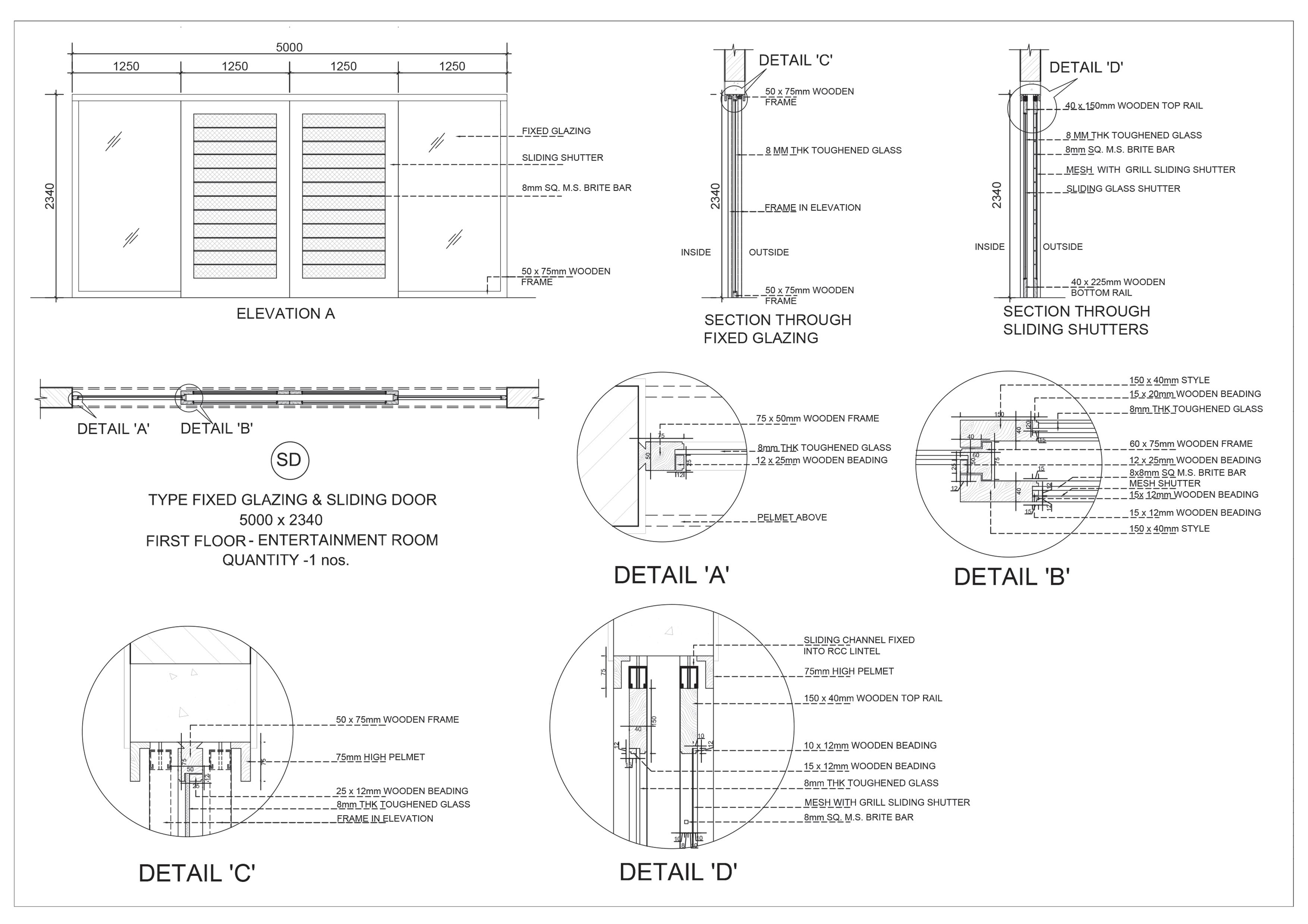


 Detail A Detail B
Detail C
THANK YOU farheen.arch@gmail.com 437-973-3318


 Studio - Fall 2018
The Paimio chair by Alvar Aalto
Steam bent furniture by Bar Gantz Inspiration
Mock-up


 Wood steaming set up
Jig for stacking seat layers
Steamed wooden strips bent and clamped
Layer 1-transverse
Cross lamination of seat layers on the jig


 Layer 2- longitudinal
Front legs
Layer 3- transverse
Center frame
Dowel reinforcement for center frame

 Dowel reinforcement
1. Glue-laminated front leg
2. Center frame assembly
3. Glue-laminated center frame
4. Front leg and center frame attachment
5. Seat attachment to leg frame
Dowel reinforcement
Dowel reinforcement
1. Glue-laminated front leg
2. Center frame assembly
3. Glue-laminated center frame
4. Front leg and center frame attachment
5. Seat attachment to leg frame


 Bar counter design

