6 minute read
ENGINE SYSTEM DIAGNOSIS
FUEL AND AIR SYSTEM OPERATION
Function:
Advertisement
Fuel system supplies fuel to injection nozzles. The air intake system filters and supplies air needed for combustion.
Theory of Operation:
MX1186
F
B C
A D E
Fuel System:
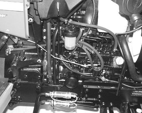
A mechanical fuel transfer pump (A) draws fuel from the tank outlet (B). The low pressure fuel from the fuel pump flows through the filter/water separator (C) to the fuel the injector pump inlet (D). The injection pump then directs high pressure fuel through the injector lines (E) for combustion. Excess fuel is returned, along with fuel from the injectors, through the return line (F) to the fuel tank. If the unit runs out of fuel, there are two air bleed lines that allow air to escape from the top of the filter and the injection pump. These two lines allow the system to be self bleeding. The engine speed is controlled by the throttle lever and rod. The rod is connected to the injection pump governor control lever. The fuel shutoff solenoid controls the injection pump shutoff shaft. When the solenoid is retracted (key in the START or ON position), the engine can be started. When the key is turned off, return springs on the shutoff shaft, extend the solenoid, moving the shutoff linkage to the shutoff position. The solenoid also closes if the tractor is operated in an unsafe condition. (See “ENGINE SHUTOFF CIRCUIT OPERATION” in the Electrical section.) The injection pump meters fuel as determined by the governor and delivers it at high pressure to the injection nozzles. The injection nozzle prevents flow until high pressure is reached, opening the valve and spraying atomized fuel into the combustion chamber. Injection lines contain trapped fuel whenever injection is not taking place. A small amount of fuel leaks past the nozzle valve to lubricate the fuel injection nozzle. This leakage combines with excess fuel from the injection pump and is returned to tank. Any air in the fuel system is bled out with return fuel to the fuel tank. A fuel level sensor mounted in the fuel tank informs the operator of the fuel level.
Air Intake System:
MX1187
D

B A
MX1188
C

E
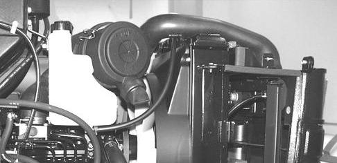
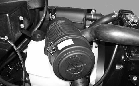
Engine intake air enters the inlet hose (A) behind the grille, and flows into the air filter body (B). The air cleaner also has a rubber, one way, unloading valve (C), that ejects heavy dirt particles from the air stream during engine operation before they reach the filters. The operator can squeeze the valve to remove the large particles. The air cleaner elements filter the air, which then flows through hose (D) to the intake manifold. An air filter restriction indicator (E) at the rear of the air cleaner informs the operator when the air filter needs servicing.
ENGINE SYSTEM DIAGNOSIS
Conditions:
• Machine parked on level surface • Park brake engaged • Key switch in OFF position • Transmission in NEUTRAL
Test/Check Point Normal If Not Normal
1. Engine dipstick and exterior engine surface. Oil level is between “L” and “H” marks. Oil filter clean. Fill oil to correct level. Change oil and filter.
Oil is not burnt, or contaminated with metal particles, fuel, or coolant. Change oil and filter. Inspect for source of contamination.
No external leakage. Check gaskets, seals, plugs, cylinder head, block, intake manifold and breather.
2. Coolant tank and radiator. Coolant level is between marks on tank when engine is warm. Coolant in radiator is full to top. Add proper coolant.
Coolant is not contaminated with oil, fuel or discolored brown. Drain and flush system. Check for source of contamination.
Radiator screen free of debris. Clean or replace.
Water pump not leaking. Inspect water pump.
Hoses not cracked or leaking. Pressure test radiator and cap.
Clamps and radiator cap tight. Tighten cap and clamps.
3. Fuel tank, pump, lines, filter shutoff valve. Fan belt tight, not glazed or cracked. Replace belt and adjust tension.
Fan blades not damaged or warped. Replace fan.
Fuel level correct, not contaminated. Correct grade of fuel, no water in fuel. Drain and clean fuel tank. Add fresh fuel.
Fuel pump in-line filter free of debris. Replace filters.
Fuel shutoff valve in “ON” position. Move to “ON” position.
Fuel hoses not cracked or leaking. Replace.
Fuel hose clamps tight. Replace or tighten clamp.
4. Air filter and air intake. Air filter hose not cracked, clamps tight. Element not plugged. Air filter housing sealed, no dirt tracking inside filter element. Replace and tighten clamps. Replace element or housing.
5. Fuel shutoff solenoid. (Key in RUN position.) Fuel shutoff solenoid must pull in and stay in. Solenoid must bottom out. Shutoff shaft must still move slightly. Clean any dirt from under solenoid boot. If solenoid will not pull in and hold in, See “FUEL SHUTOFF SOLENOID CIRCUIT DIAGNOSIS” in Electrical section.
TESTS AND ADJUSTMENTS
CYLINDER COMPRESSION TEST
Reason:
To determine the condition of the pistons, rings, cylinder walls and valves.
Equipment:
• JT01682 Compression Gauge Assembly • JDG560 Adapter
Procedure:
1. Remove the injection nozzles.
B A
T6333EU
2. Install the heat protector from end of injector and install JDG560 adapter (A). 3. Install JT01682 Compression Gauge Assembly (B) and JDG560 Adapter. 4. Disconnect the fuel control solenoid connector.
IMPORTANT: DO NOT overheat starting motor during test.
5. Crank the engine for five seconds with the starting motor. Minimum cranking speed is 250 rpm. 6. Record the pressure reading for each cylinder.
Compression Pressure: Standard . . . . . . . . . . . . 3233 ± 97 kPa (469 ± 14 psi) Minimum . . . . . . . . . . . 2551 ± 97 kPa (369 ± 14 psi) Maximum difference between cylinders . . . . . 248 ± 48 kPa (36 ± 7 psi)
Results:
• If the pressure reading is below specification, squirt clean engine oil into the cylinders through the injector ports and repeat the test. • If the pressure increases significantly, check piston, rings, and cylinder walls for wear or damage. • If the pressure does not increase significantly, check for leaking valves, valve seats or cylinder head gasket.
SLOW IDLE ADJUSTMENT
IMPORTANT: The slow idle adjustment is the only adjustment that can be made on this engine.
The fast idle and torque capsule adjustments are pre-set by the engine manufacturer to comply with strict EPA/CARB emissions requirements, and are adjustable ONLY by authorized diesel service facilities.
Reason:
To achieve proper slow idle rpm setting. Provides adequate rpm to keep the engine running smoothly without stalling.
Equipment:
• JT05719 Hand Held Digital Tachometer
NOTE: Make sure the air cleaner is clean and not restricted. Replace the air cleaner element as necessary.
Procedure:
1. Place a small piece of reflective tape on the crankshaft pulley. 2. Start the engine and run for 5 minutes to attain operating temperature. 3. Move the throttle lever to slow idle position. 4. Use JT05719 Hand Held Digital Tachometer to check engine speed at the crankshaft pulley. 5. Visually check that the injection pump throttle lever is against slow idle stop screw. Slow idle speed is


