10 minute read
Evaluation of Mixing, Mass Transfer Operation and Maintenance, Energy, and Material Requirements for Hydrogen


FWRJ Evaluation of Mixing, Mass Transfer, Operation and Maintenance, Energy, and Material Requirements for Hydrogen Sulfide Oxidation at the Orlando Utilities Commission Water Treatment Plants
Srikanth S. Pathapati, Chris Schulz, John Healy, Brad Jewell, Eric Jones, Robert Sumpter, Quyen Newell, and Thomas Steinke
Advertisement
Ozonation is an efficient and fast method for odor control and removal of hydrogen sulfide (H2S) from well water. The Orlando Utilities Commission (OUC) is the second largest municipal utility in Florida and 14th largest in the United States. Starting in the late 1990s, the OUC installed air-fed and liquid oxygen (LOX)fed ozonation systems using fine bubble diffusers (FBD) for gas dissolution, followed by over-and-under contacting basins for mixing, disinfection, and completing oxidation reactions and blending at eight water treatment plants for mitigation of H2S from well water.
The OUC continually takes advantage of technological changes, such as advances in ozone generation and dissolution to improve its treatment processes. It has also been upgrading older ozonation systems with newer oxygen-fed ozone generators, coupled with sidestream venturi injection and pipeline contacting designed with advanced modeling techniques.
This article presents data from retrofit projects at the OUC Southwest Water Treatment Plant (WTP), Conway WTP, and Pine Hills WTP, which involved replacement of FBD with sidestream venturi injection ozone dissolution technologies. The two technologies are compared based on mixing and mass transfer efficiency, operation and maintenance (O&M), specific energy, materials, and required physical footprint per unit mass of ozone transferred. With respect to mixing efficiency, a statistical analysis was performed to compare the coefficient of variation of ozone residual for both technologies and the impacts on control schemes for H2S oxidation.
Background
The OUC draws water from the Lower Floridan aquifer from a system of 31 deep wells that contain varying amounts of naturally occurring H2S. The H2S is oxidized rapidly with ozone to form sulfate, which eliminates H2S-related taste and odor and reduces the amount of chlorine required for residual disinfection.
In 1997, OUC installed an air-fed ozone system using FBD and over-under contacting for the reduction of H2S. Eventually, all OUC WTPs implemented ozone for treatment of sulfide-containing wells (Rakness, 2011).
Almost a decade ago, OUC began the process of upgrading all water treatment facilities from FBD to sidestream injection (SSI) and from air-fed ozone generators to LOX-fed ozone generators.
Each plant has a minimum of two ozone contactor basins. Currently, the three plants (Southwest, Conway, and Pine Hills) have been retrofitted from FBD to SSI, which are the two main methods of ozone dissolution. The ideal ozone contacting system would have homogenous gas-liquid mixing in the dissolution zone, followed by near plug flow in the contacting/reaction zone. Ozone contacting for municipal water treatment is conducted in baffled basins, either vertical (over-under) or horizontal (side to side).
The design of FBD systems is similar to aerated bubble columns, with guidelines for maximum gas loading rate, floor area coverage, contact time, and water column depth. Separate dissolution chambers and
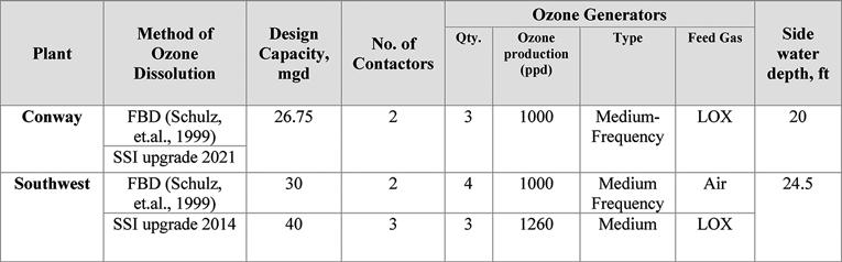
Table 1. Summary of Previous and Current Designs Srikanth S. Pathapati, Ph.D., is director of research and development, and Thomas Steinke is director of municipal sales, with Mazzei Injector Co. LLC, in Bakersfield, Calif. Chris Schulz, P.E., is senior vice president with CDM Smith in Denver. John Healy, P.E., is senior engineer with CDM Smith in Maitland. Brad Jewell is director of water production; Eric Jones is supervisor of maintenance, water production; Robert Sumpter is supervisor of operations, water production; and Quyen Newell, P.E., is senior engineer, water production, with Orlando Utilities Commission.
contact chambers are required and the number of chambers depends on the size of the applied dose and type of application. The FBD is known to be generally less energyintensive due to its passive mixing imparted by ozone bubbles rising through the water column. The FBD has also been shown to have higher O&M costs due to plant shutdowns and confined space entry for maintenance and replacement of the diffuser gaskets and diffusers (Snider, 2020; Smith et al., 2017).
With SSI dissolution systems, a sidestream is pulled from the bulk flow and ozone gas is injected via venturi injectors. The ozonated sidestream is then remixed into the bulk flow with jet nozzles, downflow tubes, or static mixers, or a combination thereof. The process of rapid ozone dissolution starts in the venturi injector and pressurized sidestream piping, continuing in the main pipeline or over-under contactor. The mixing zone can have a smaller footprint when compared to diffusers, especially at high applied doses. This approach avoids confined space entry into the contactor and typically requires less maintenance, but needs careful design to maximize the active mixing and minimize sidestream pump energy use.
The SSI can be applied both to pipeline contactors and traditional contact basins; pipeline contacting offers better control and near plug-flow conditions. The sidestream systems, pipeline, and traditional contact basins provide the flexibility of turndown as flow rates and doses change. The engineering solution to this has been to utilize tracer studies (when available) to identify and reduce dispersion in contactors. The solution can add significant increases to overall costs due to structural modifications. These modifications can include adding more baffles and/or inlet flow energy dissipation methods; however, engineers often do not have access to tracer studies and actual flow rates may vary from tracer runs.
The volumetric efficiency of the contactor can have a direct impact on ozone generation costs, due to poor mixing efficiency. In recent years, computational fluid dynamic (CFD) modeling has been successfully applied to improve contactor design for reducing short-circuiting and improving basin hydraulics.
Due to the passive mixing of FBD basins, they require deeper water columns (20 to 25 ft) to increase static pressure over the diffusers, thereby minimizing the size of bubbles released from the diffusers and improving ozone gas transfer into water. The two-stage, active mixing imparted with venturis and nozzles, however, creates a constant shearing of bubbles, resulting in improved transfer due to the rapid renewal of the gas-liquid interface; therefore, the higher mixing energy of SSI systems can be used to decrease the contact basin water column depth (typically less than 16 ft).
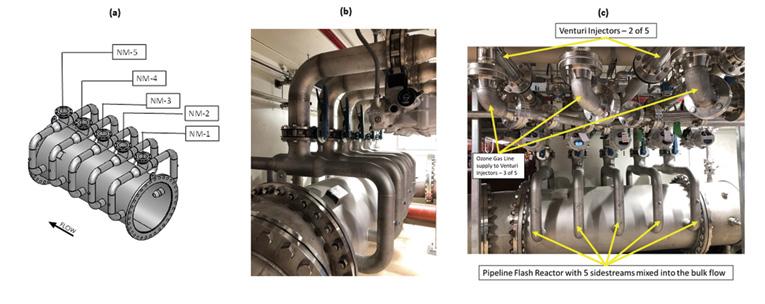
Figure 1. (a) Mazzei pipeline flash reactor, (b) Conway Water Treatment Plant ozone sidestream injection into bulk flow, and (c) Conway Water Treatment Plant pipeline flash reactor, venturi injectors, and ozone gas lines.
Previous Work
This article builds on a peer-reviewed paper by Schulz and Bellamy (2000) on the role of mixing in ozone systems. Key results from that study include SSI-based ozone contactors that were shown to: S Improve mixing, with velocity gradient values ranging from 600 to 900 per second, three to eight times higher than
FBD. S Improve mixing, indicated by coefficients of variation ranging from 5 to 10 percent, compared to 20 to 45 percent with FBD systems. S Control ozone dosage, which is not instantaneous with FBD, and control changes need to account for this built-in detention time requirement. S Optimize design of the pipeline contactor, which is critical for achieving homogenous mixing.
The objective of this study is to compare the performance of FBD and SSI systems for H2S oxidation with ozone with respect to the following performance metrics: S Mass transfer efficiency S Total specific energy (mass transferred per unit energy consumed) S Total pumping energy S Mixing efficiency S O&M differences
Methodology
Description of Facilities
Southwest Water Treatment Plant
The Southwest WTP includes three parallel ozone contactor trains and has a design capacity of 40 mil gal per day (mgd). In early 2010, the ozone system was upgraded with new ozone generation equipment and the existing FBD dissolution system was replaced with a new SSI system. The ozone improvements project was completed in late 2014 and early 2015.
The design replaced four air-fed generators with three 1,260 pounds per day (ppd) oxygen-fed generators to deliver an applied ozone dosage of 7.4 to 9.84 mg/l at ozone gas concentrations of 8 to 12 percent wt. The contact basins at Southwest had 1,656 diffusion stones that were replaced by five, small venturi gas injectors. The injectors discharge into a common pipeline flash reactor (PFR) located directly upstream of the ozone contact basins. This design modification allowed the existing dissolution chambers in the contactor to now function as reaction chambers. The design team used multiple small injectors to provide turn down that would allow the plant to minimize pump energy costs by reducing the number of ozone injectors required at low to average ozone production rates.
Details of the SSI-PFR design for the Southwest plant are available elsewhere (Pathapati et al., 2016) and are not reproduced here.
Conway Water Treatment Plant The upgraded Conway WTP includes two parallel contactor trains and has a design capacity of 26.75 mgd, with a maximum Continued on page 42 Florida Water Resources Journal • March 2022 41
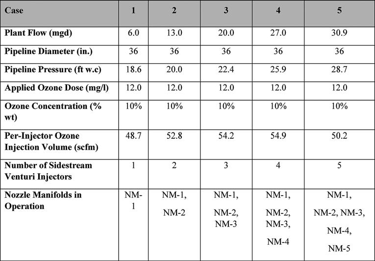
Continued from page 41 consumptive use permit (CUP) allocation of 30.9 mgd. The redesigned ozone dissolution system uses sidestream ozonated water, which is mixed with bulk water in the pipeline via one PFR, as shown in Figures 1A, 1B, and 1C. The PFR consists of five nozzle manifolds (NM), each connected to one venturi injector (five injectors total) and each equipped with two discharge nozzles (10 nozzles total). The NM on the PFR are labeled as NM-1, NM-2, NM-3, NM-4, and NM-5, with NM-1 located the furthest upstream and NM-5 located furthest downstream. A Westfall Static Mixer (model 2800) is included in the SSI system. A summary of previous and upgraded designs is provided in Table 1.
Conway Water Treatment Plant Design With Computational Fluid Dynamic
The CFD modeling was used to design the ozone dissolution and mixing system with the pipeline contactor. The geometry and the mesh are shown in Figure 2.
The geometry was meshed with approximately 5.7 mil locally refined hybrid cells. All piping was assumed to be constructed of Schedule 40 stainless steel. For all cases, the primary phase is the untreated water entering through the main pipeline and the secondary phase is the sidestream gas; the water temperature is assumed to be 20°C.
Input data for CFD modeling is listed in Table 2. All analyses are steady-state and steady-flow. Flow rates other than those specified and start-up/ramp-up conditions are not part of the scope of this study. In
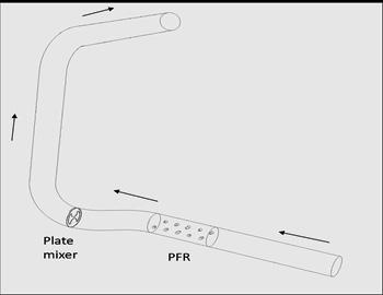
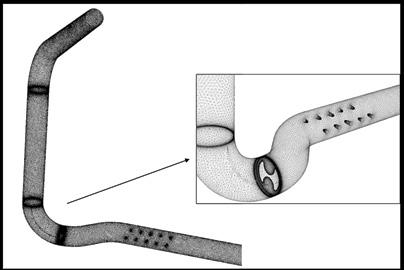
Figure 2. Pipeline flash reactor geometry and mesh for computational fluid dynamic model at Conway Water Treatment Plant.
Table 2. Inputs to Computational Fluid Dynamic Model for Sidestream Injection Pipeline Contactor Design addition, any effects of undefined upstream plumbing and hydraulics, as well as the presence of gas slugs, pulsating flows, etc., are not modeled here. The vent branch downstream of the air dam is assumed to be closed in the model, and CFD modeling was performed with ANSYS Fluent (v19.2).
Mixing Energy Calculations
The following equations were utilized for mixing energy calculations: Hydraulic HP = head (ft) x flow rate (gal per min [gpm]) x (specific gravity)/3956 (1)
Brake HP = Hydraulic HP/pump efficiency (2)
Power input for diffusers = P = 35.28 Q in [(h+ 33.9)/33.9] (3)
Where “h” is the depth of the gas diffuser below the water surface (ft)
Power input for SSI = Injector inlet pressure (ft of water) x flow rate (gpm)/3956 (4)
Velocity gradient, G = (5)
Where “P” is power dissipated in ft-lb/s, ‘µ” is the viscosity of the water in Ib-s/ft2 , and “V” is the volume in ft3 of the mixing reactor.
Power/Volume = total energy input in HP/(volume in gal) (6)
Operation and Maintenance Considerations
Automation and Overfeed
The goal of achieving target mass transfer efficiency is important, as well as maintaining the stability of ozone residual. The coefficient of variation (COV) of dissolved ozone residual downstream of the ozone dissolution process can be used to evaluate the stability of the ozone residual. As plants move toward automation, where the applied ozone dose is adjusted based on measured residual readings, stable ozone residuals are required to provide this level of automation. Tighter control of the ozone dose in response to plant flow or water quality changes will meet treatment performance targets (i.e., complete sulfide oxidation) at the least cost.
The COV, also known as concentration variance, is expressed as follows:Continued on page 44


