12 minute read
Guidelines for Use of Mini-Horizontal Directional Drilling for Placement of High-Density Polyethylene Pipe for Water
FWRJ Guidelines for Use of Mini-Horizontal Directional Drilling for Placement of High-Density Polyethylene Pipe for Water Applications
Lawrence M. Slavin
Advertisement
User-friendly guidelines for the placement of high-density polyethylene (HDPE) pipe with mini-horizontal directional drilling (HDD) equipment have been developed by the Municipal Advisory Board (MAB) of the Plastics Pipe Institute (PPI). Previously available as Technical Report TR-46 and published in 2009, “MAB Guidelines for Use of Mini-Horizontal Directional Drilling for Placement of HDPE (PE4710) Pipe in Municipal Applications” emphasizes the applications for potable water and sewer projects and provides detailed information for both iron pipe size (IPS) and ductile iron pipe size (DIPS) constructed of the latest PE4710 material.
The MAB-7 provides information analogous to that provided in the American Society for Testing and Materials (ASTM) F1962, “Standard Guide for Use of MaxiHorizontal Directional Drilling for Placement of Polyethylene Pipe or Conduit Under Obstacles, Including River Crossings,” but at a level appropriate for the less-complex mini-HDD technology and typical project characteristics.
The MAB-7 includes the following 10 main sections, as well as six supporting appendices: S Scope S Referenced Standards and Specifications S Terminology S Preliminary Site Investigation S Safety and Environmental Considerations S Regulations and Damage Prevention S Pipe Design and Selection Considerations S Bore Path Planning and Drill Rig Setup S Implementation S Completion
The document is readily available to the public via the website of PPI at http://plasticpipe. org/pdf/mab-7-mini-hdd-guide.pdf.
Background
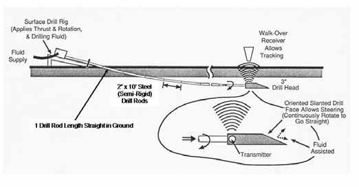
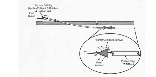
Figures 1 and 2 illustrate typical mini-HDD equipment, and pilot boring and back-reaming operations, including placement (pullback) of the product pipe, such as for water distribution applications.
Mini-HDD is typically employed for boring segments less than 600 ft in length, at depths up to 15 ft, and placing pipes up to 12 in. in diameter. In contrast, maxi-HDD technology is capable of accurately boring holes thousands of ft in length, and placing pipes of 48 in. or greater at depths up to 200 ft. Maxi-HDD machines may weigh as much as 30 tons (or greater) and are appropriate for placing pipes under large rivers or other major obstacles.
The ASTM F1962 provides recommended procedures for the placement of HDPE pipe using maxi-HDD. The ASTM document provides overall guidelines, addressing preliminary site investigation, safety and environmental considerations, regulations and damage prevention, bore path layout and design, implementation, and inspection and site cleanup. One of the significant contributions of ASTM F1962 is the provision of a rational, analytical method for selecting the polyethylene pipe strength based on the estimated installation and postinstallation (operational) loads on the polyethylene pipe. The ASTM F1962 therefore provides a means of determining project feasibility, as well as initial design information.
While the ASTM F1962 guidelines are convenient and practical to apply by experienced engineers for a maxi-HDD operation, the corresponding equations and procedures represent relatively complicated formulas (and an extensive tedious methodology) when considering smaller, lower-cost operations associated with typical mini-HDD applications, including placing a new water or sewer distribution line.
Some mini-HDD installations may be considered to be relatively critical or approach
Lawrence M. Slavin, Ph.D., is principal of Outside Plant Consulting Services Inc. in Rockaway, N..J.
Continued from page 8 limits with respect to the capability of the available drill rig and/or the strength of the product pipe being installed, and for which a relatively convenient, although possibly less precise, design procedure would be desirable.
Any construction procedure must address basic safety rules, avoid damage to existing facilities, adhere to applicable government regulations, and consider environmental issues. The MAB-7 was therefore developed to serve as an inclusive document, providing practices for placement of HDPE (PE4710) pipe for municipal applications using mini-HDD.
In particular, MAB-7 includes easy-tounderstand guidelines for proper drill rig positioning, consistent with meeting required placement depths and drill rod capabilities, as well as for estimating the relevant forces and effects present during installation, allowing proper selection of the pipe strength.
Description
The MAB-7 contains 10 main chapters, or sections, as briefly described, supplemented by several appendices.
Scope, Related Industry Standards, and Terminology (Sections 1, 2, and 3)
The MAB-7 addresses planning, design, drill rig setup, and installation practices for the placement of polyethylene pipe using miniHDD equipment. The primary focus is on commonly used HDPE pipe with a material designation code of PE4710. Depending on the diameter, polyethylene pipe may be supplied in continuous lengths on reel or discrete segments, which would typically be fused together in the field.
Preliminary Site Investigation (Section 4)
The general feasibility of utilizing miniHDD technology for placing the proposed pipeline(s) must be determined prior to any proposed construction activities. Such a preliminary investigation is required to gain an understanding of the local characteristics in order to help ensure a cost-effective, efficient, and above all, safe operation. Of particular importance, and as addressed in other sections of the guidelines, is the awareness of existing utilities in the vicinity of the proposed pipeline and the need to maintain minimum specified clearances during the construction process.
Safety and Environmental Considerations (Section 5)
Safety is a primary concern during any activity, including construction utilizing mini-HDD equipment and procedures. Potential safety issues fall into two general categories: those directly related to the setup and operation of the mini-HDD equipment; and those associated with the proper location, identification, and marking procedures intended to avoid contacting and damaging existing utilities. Section 5 of MAB-7 addresses the first category, providing practices to avoid or minimize equipment-related risks during miniHDD operations.
Employees must be trained to prevent injuries to themselves and others during the operation of the equipment and be prepared to mitigate the effects of accidents. Electric power and gas-line strikes are specifically addressed. Although not considered to be hazardous materials, the proper handling and disposal of drilling fluid is also discussed to avoid possible environmental issues.
Regulations and Damage Prevention (Section 6)
Section 6 of MAB-7 addresses the second category of potential safety issues, focusing on procedures to eliminate or reduce hazards associated with damaging existing utilities, including during the initial boring or backreaming operations.
Recommended practices include: S “Call before you dig” (811). S Properly locating and marking existing utilities, as well as exposing such utilities at anticipated crossings with the bore path. S Avoiding mechanized digging within the required tolerance zone. S Use of subsurface utility engineering, as described in the Construction Institute/
American Society of Civil Engineers (CI/
ASCE) 38, “Standard Guidelines for the
Collection and Depiction of Existing
Subsurface Utility Data.”
Pipe Design and Selection Considerations (Section 7) and Bore Path Planning and Drill Rig Setup (Section 8)
Sections 7 and 8 contain particularly useful information, provided in a convenient format, as discussed in greater detail.
Implementation (Section 9)
It’s beyond the scope of the MAB-7 guidelines to provide detailed operational procedures for the various mini-HDD and auxiliary equipment, which are generally available from the manufacturers or other sources. Proper procedures, however, are described for pilot boring, tracking, steering, reaming, and pullback operations, as well as pipe handling/connection and recordkeeping.
Completion (Section 10)
Following installation of the pipe, it’s necessary to confirm the viability of the new facility, provide a permanent record of the actual placement location, and ensure final site cleanup. The integrity of the pipes should be appropriately verified, depending on the application and the owner’s specifications. Any mud or debris that may have entered the pipe must be expelled and the pipeline flushed, and the system then pressurized and checked for leakage.
Table 1. Safe Pull Tension (lb), High-Density Polyethylene (PE4710) Pipe, 1-Hour Iron Pipe Size
Table 2. Safe Pull Tension (lb), High-Density Polyethylene (PE4710) Pipe, 1-Hour Ductile Iron Pipe Size
Continued from page 10
Appendices (A - F)
The 10 main sections outlined are intended to provide user-friendly guidelines for the installation of HDPE (PE4710) pipe in municipal applications using mini-HDD. These sections are supported by six appendices that provide examples of the application of the information described in Sections 7 and 8, as well as the theoretical basis for their development.
The MAB-7 contains a convenient calculation method for the selection of the HDPE (PE4710) pipe strength. The procedure is presented in an easy-to-understand format, appropriate for users with various backgrounds. The procedure provides a means of selecting the pipe strength to avoid collapse due to hydrostatic pressure at the desired placement depth, as well as to withstand the required pulling loads during installation.
Minimum Wall Thickness Based on Depth
The pipe strength is directly related to the wall thickness, as specified by its dimension ratio (DR), which is defined as the pipe outer diameter by the wall thickness. The MAB-7 guidelines indicate that essentially all the commonly used wall thicknesses for PE4710 pipe, with the possible exception of DR 17 pipe, would be sufficiently strong for depths to approximately 15 ft, the typical limit for mini-HDD installations.
A DR 17 pipe should generally be limited to less than a 10-ft depth, although 15 ft may also be acceptable in some cases.
For depths greater than 15 ft, thin-walled pipe, or special situations, the adequacy of the product for the application should be verified using the supplementary information provided in the document. In some cases, such as thinwalled pipe and/or relatively large depths, special practices or precautions not typically employed during mini-HDD installations may be required. For example, filling the pipe with water during pullback simultaneously reduces the net external hydrostatic pressure during (and following) installation and the buoyant weight of the pipe, resulting in reduced pull loads.
Minimum Wall Thickness Based on Pulling Load
Table 1 provides the “safe pull tension” for HDPE (PE4710) pipe as a function of pipe (nominal) diameter and wall thickness (DR value) for IPS pipe sizes, while Table 2 provides the strengths for DIPS pipe sizes. These values are intended to account for the cumulative load duration on the pipe, and avoid nonrecoverable viscoelastic deformation. The indicated strengths are based on the minimal required wall thickness, as opposed to that of the actual manufactured product, and therefore underestimate the average safe pull tension by approximately 6 percent.
The following simplified equation has been developed for the purpose of estimating the pull load during mini-HDD installations of polyethylene pipe:
Tension (lb) = [Bore Length (ft) x Buoyant Weight (lb/ft) x (1/3)] x (1.6)n
The buoyant weight may be conveniently determined as follows:
Buoyant Weight (lb/ft) = ½ [Pipe Outer Diameter (in.)]2 – Pipe Weight (lb/ft)
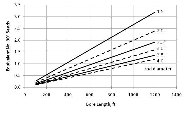
The term “n” is equal to the number (including fractions) of effective 90-degree bends due to cumulative route curvature where n = n1 + n2. The quantity n1 is the number of planned (deliberate) 90-degree route bends, and n2 is the number of effective route bends resulting from typical path corrections and route curvature during the pilot boring operation for which the following guideline is suggested:
n2 = [Bore Length (ft)/500 ft] x [2-in./ Rod Diameter (in.)]
The quantity n2 is shown in Figure 3 for various rod diameters.
For a specified pipe diameter, the procedure for selecting an appropriate pipe strength (DR value) consists of comparing the estimated pull load to the strengths in Table 1 or 2. This procedure is similar to, but much less complicated than, that incorporated in ASTM F1962 for the more-sophisticated maxi-HDD installations. The present miniHDD calculations will generally result in considerably shorter placement distances than those corresponding to the design methodology provided in ASTM F1962, which may result in possible pullback distances of several thousands of ft.
Mini-HDD installations suffer relative to those performed using typical maxi-HDD technology due to the lesser degree of control (e.g., greater cumulative route curvature) and the desire to forego the use of antibuoyancy techniques, such as inserting water into the pipe during pullback to reduce buoyant weight and significantly reduce required pull loads.
In general, the preceding formulas and methodology are recommended for estimating pull loads for mini-HDD installations. Other methods for determining pulling loads are typically based on well-controlled maxi-HDD installations and are not representative of actual mini-HDD applications with respect to anticipated pull loads.
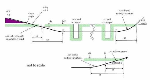
Figure 4. Drill Rig Setup and Related Distances
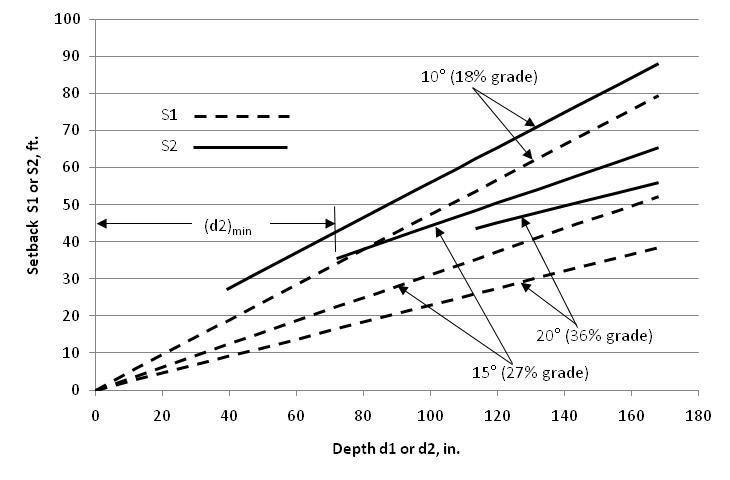
Figure 5. Drill Rig Minimum Setback Distance Drill Rods: 10 Ft Long, 100-Ft Radius of Curvature
In comparison to maxi-HDD installations, for which the design of the bore path is typically performed by experienced engineers or organizations, the mini-HDD contractor is generally responsible for cost-effectively accomplishing this task. Thus, MAB-7 provides user-friendly drill rig setup and bore path planning information that is consistent with meeting the requirements of the project owner, including geographic constraints and placement depth. The ability to satisfy the overall requirements depends on the bending characteristics of the steel drill rods and the drill rig setup parameters.
Figure 4 illustrates a typical mini-HDD bore vertical profile trajectory, including occasional pits along the route. These pits may be required for pipe splicing, completing lateral connections, or to expose existing utilities. The pits may also be useful for collecting drilling fluid from the boring or reaming operations. The bending capability and length of the drill
rods, and their entry angle to ground surface, will determine the minimum depth achievable at the beginning of the bore path. In order to achieve a specified depth at a particular point toward the beginning of a pilot bore operation, the front of the drill rig must be located at an appropriate distance rearward from the point of interest. Knowledge of such minimum setback requirements is important with respect to verifying that there is sufficient space available to properly perform the miniHDD operation. For example, point 1 (Figure 4) is located directly along the entry path of the drill rod, where the resulting bore path is inclined at the entry angle and for which the setback distance corresponding to reaching the depth (d1) is designated as S1. The S1 Continued on page 14 Florida Water Resources Journal • October 2021 13
