Work Sample_You Chia Lai_2022

Page 1

Work Sample 2012 ~ 2021 YOU CHIA
LAI
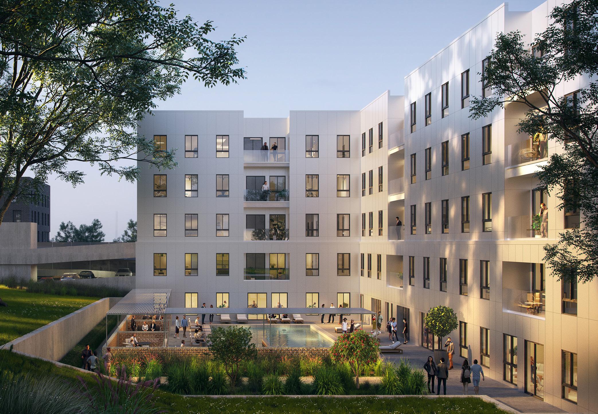
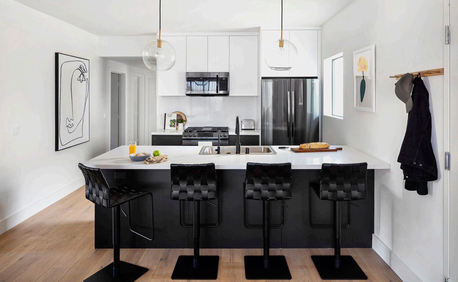
YOU CHIA LAI / WORK SAMPLE 2 Common Englewood Multi-Family Development in Atlanta Architectural Consultation & Interior Design | 244 Beds | Common | Not-Built | Phases Involved: SD, DD 3'-0" 7'-2" 28'-4 3'-0" VIF Align Align C Wall to Column C Wall to Column C Wall to Column Align 12'-1" +/12'-11" 15'-2 6'-21 Per AOR Plan 12'-2" 3'-0" VIF 7'-7" +/EQ. EQ. 15'-7" Per AOR Plan Align FL 01 FL 01 FL 01 FL 01 FL 01 FL 01 FL 01 FL 01 FL 01 WL 01 WL 01 WL 01 WL 01 WL 01 WL 01 WL 01 WL 01 WL 01 WL 01 WL 01 WL 01 WL 01 WL 01 WL 01 WL 01 WL 01 WL 01 WL 01 WL 01 WL 01 WL 01 WL 01 WL 01 WL 01 WL 01 Line of Soffit above, Typ. Line of Soffit above, Typ. 4'-3" Wall below Countertop Booth Seating Booth Seating Booth Seating Booth Seating Storage WL 01 17'-1 2 VIF 4'-6" ID 4.0 01 ID 2.0 ID 2.0 ID 4.0 05 ID 4.0 08 01 ID 2.0 02 03 03 ID 3.0 01 ID 2.0 ## LOBBY A101 LOBBY MAIL A110 JANITOR CLO. LOBBY WORKSPACE A103 LOBBY HALLWAY A104 A105 A106 A107 A108 B1 D3 D3 G1 G2 G3 B1 G4 12'-4 VIF W4 W4 W4 W6 W4 W4 W4 W4 W4 W4 C EQ. EQ. of Col. L of Col. L of Col. 13'-21 L WL 01 WL 01 06 FL 06 SMALL ROOF DECK COMMON ENGLEWOOD Common Living INTERIOR DESIGNER 335 Madison Avenue, Suite New York, NY 10017 www.common.com 577 Englewood Avenue SE, Atlanta, GA, 30315 YCL, 11.01.2019 1 General Notes: Issue Date No. Project: Drawing Title: Date: Drawing by: DWG No. 11.01.2019 100% ID DD Set NOT FOR CONSTRUCTION 1/4" = 1'-0" BLDG. A LOBBY & WORK SPACE FINISH FLOOR PLAN 01 BLDG. A SMALL ROOF DECK FINISH FLOOR PLAN 02 ID 1.0 BUILDING A AMENITY INTERIOR DESIGN PLAN 1. All dimensions are to finish unless beyond the scope of interior design. Flush floor transition is preferred. Lobby Finish Floor Plan
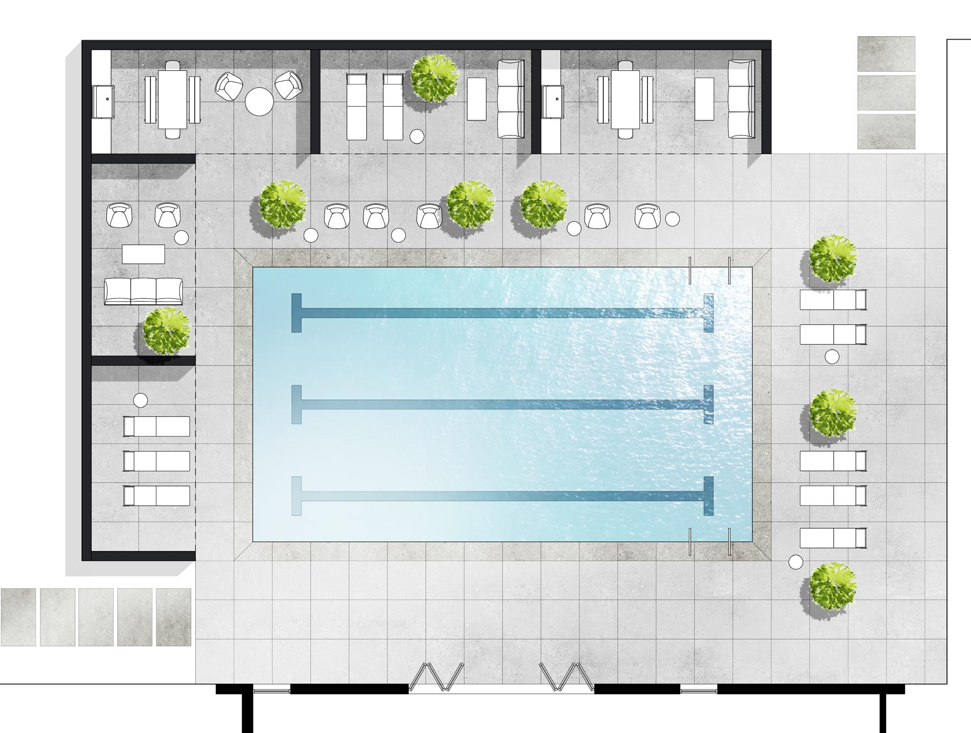
YOU CHIA LAI / WORK SAMPLE 3 Englewood 25 Bldg. B
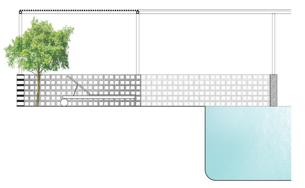
9'-0" Clear to B.O. Steel Beam 9'-4" 6"x8"x16" CMU running bond block wall cavities exposed 11'-10" 9'-0" Clear to B.O. Steel Beam 3'-0" 4"x4"x2 Stl. tube frame 1 "x1 "x Stl. tubes @3 " O.C. 4"x4"x " Stl. Column 4"x4"x Stl. Column 6"x8"x16" CMU running bond block wall cavities exposed 1/2" = 1'-0" BLDG. B POOL CABANA ELEVATION 01 1/2" = 1'-0" BLDG. B POOL CABANA SECTION 03
Pool - Design
Outdoor Pool Layout Outdoor Pool Section Outdoor Pool Section
YOU CHIA LAI / WORK SAMPLE 4 1 2 2'-0" 2'-4" 2'-0" 1 2 Reveal, Typ. Reveal, Typ. SIM EQ. EQ. EQ. EQ. Typ. Typ. Typ. CL CL CL EQ. 1'-4" 1'-4" EQ. Concealed Mtl. Bracket 16" O.C., Typ. 4'-3" ID 4.0 02 ID 5.0 05 ID 4.0 03 ID 5.0 05 ID 4.0 04 +12" +12" +12" +12" +12" +12" +12" +12" 3" CL Typ. 3" Typ. CL 9'-6" 1/2" = 1'-0" BLDG. A LOBBY BUILT-IN BOOTH ENLARGED PLAN 01 1'-6" 1'-6" 2'-6" Typ. Typ. Typ. Concealed Mtl. Bracket on 2x4 Stud, 16" O.C., Typ. 2x4 Wall Stud, 16" O.C., Typ. Horizontal Wood Strapping on Wood Studs MIL 01 MIL 01 MIL 01 Concealed Mtl. Bracket on 2x4 Stud, 16" O.C., Typ. 512" Decorated Wood Panel on Plywood Backing Board, Typ. MIL 02 ID 5.0 06 ID 5.0 07 20'-9" VIF 3'-0" VIF CL CL CL CL CL CL CL CL CL CL CL CL CL CL CL 1'-4" 1'-4" 1'-4" 1'-4" 1'-4" 1'-4" 1'-4" 1'-4" 1'-4" 1'-4" 1'-4" 1'-4" 1'-4" 1'-4" EQ. EQ. Conceled Metal Bracket, 16" O.C., Typ. Line of Knee Wall below 9" Decorated Wood Panel on Wall MIL 03 ID 4.0 07 ID 4.0 06 MIL 02 +42" +42" +42" +42" CL 2'-0" 2'-0" CL CL CL EQ. EQ. EQ. 2'-0" 7'-4" +/EQ. EQ. EQ. MIL 01 ID 4.0 09 ID 4.0 10 4" 112 3'-0" 13 4", Typ. 13 4", Typ. CL CL 13 4 " Typ. CL MIL 01 MIL 01a 6'-0" CL Decorated Wall Sconce 4" 112 3'-0" 13 4 " Typ. CL MIL 01 MIL 01a MIL 06 Decorative Wall Sconce 6'-0" ID 5.0 08 (D.W.) 1'-8" 1'-8" 1'-8" 1'-8" 1'-8" 1'-8" EQ. EQ. CL CL CL CL CL CL CL Concealed 1'-63 4 4'-0" 1'-6" 1'-6" 2'-0" 3'-0" 2'-0" EQ. 2'-1" 1'-11" 18'-0" 3'-0" 2'-6" CLR. Line of Knee Wall below ID 4.0 17 ID 4.0 14 ID 4.0 12 ID 4.0 15 AP 02 AP 01 AC 05 AC 05 PL 02 PL 01 CLR. 112 2'-6" 4" 3'-0" 112 6" Typ. MIL 04a MIL 05 2'-6" MIL 06 1/2" = 1'-0" BLDG. A LOBBY BUILT-IN BOOTH ENLARGED PLAN 01 1/2" = 1'-0" BLDG. A LOBBY BUILT-IN BOOTH SECTION 04 1/2" = 1'-0" BLDG. A LOBBY BUILT-IN COUNTER ENLARGED PLAN 05 1/2" = 1'-0" BLDG. A LOBBY BUILT-IN COUNTER & CABINET 08 1/2" = 1'-0" BLDG. A LOBBY BUILT-IN COUNTER & CABINET ELEVATION 09 1/2" = 1'-0" BLDG. A LOBBY BUILT-IN COUNTER & CABINET 10 1/2" = 1'-0" BLDG. B CLUB ROOM WET BAR ENLARGED ELEVATION 12 4'-3" 1'-6" 2'-6" Typ. Typ. 2'-6" Typ. 9'-4" 2" 9'-6" MIL 02 MIL 02 MIL 02 MIL 02 Decorative Pendant Light 1'-0" CL Typ. Concealed Bracket Stud, 16" Typ. EQ. 9" 9'-6" 3'-0" 9'-4" 2" Countertop on Concealed Metal Brackets 2'-6" Decorative Pendant Light MIL 02 MIL 02 3'-0" 9'-4" 9'-6" Decorated Wood Panel Decorated Wood Panel Pntd. GWB MIL 03 MIL 02 MIL 02 ID 5.0 19 ID 5.0 07 SIM Veneer Plwd Pnl. 1/2" = 1'-0" BLDG. A LOBBY BUILT-IN BOOTH ENLARGED ELEVATION 02 03 1/2" = 1'-0" BLDG. A LOBBY BUILT-IN COUNTER ENLARGED ELEVATION 06 1/2" = 1'-0" BLDG. A LOBBY 07 Lobby Banquette Seating Plan Lobby Banquette Seating Elevation Lobby Banquette Seating Section
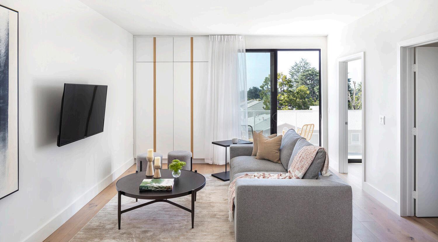
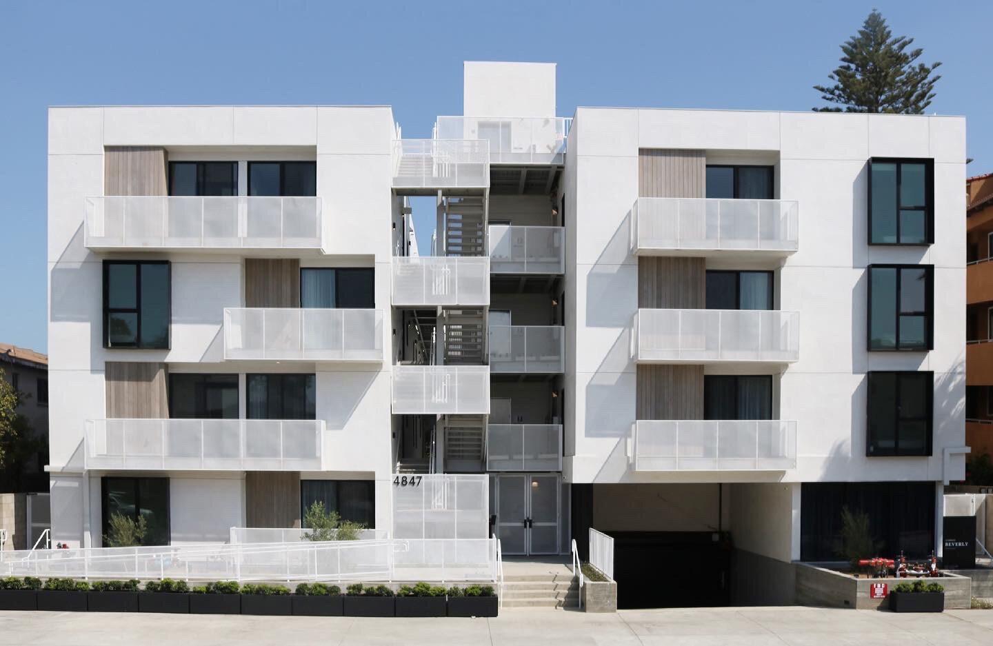
YOU CHIA LAI / WORK SAMPLE 5 Common Beverly Multi-Family Development in Los Angelas Architectural Consultation & Interior Design | 91 Beds | Common | Built | Phases Involved: SD, DD, CD ssue se s b t on arch ec g Bever y resid 4847 Beve B vd A g C 9 M R CH S O B TT N 3 LCE S SA EO 7 17 8 PLAN C 6 18 8 COORD 8 30 8 PROPE 9 07 8 B D SE 9 21 8 B D SE 2 08 9 PC VE F W W F F F M 9 WD 6 M 1 0 N 2 C 20 MT 9 C 0 UNIT 06 1 7 5 S F BD 2 BD 3 BD 4 BD 5 BD 1 BD UN T 05 1 09 S F BD 2 BD BD 5 BD 1 BD 6 OPEN TO ABV BLW OP N O BALCONY B L C O Y B L C N Y % 2% 2% K TCHEN K K TCHEN STA R 3 BATH 0 A2 2 BA H 1 1 A2 2 BATH 1 0 /A 20 02 A2 2 02 A2 0 CL CL C C CL OPEN TO W D OPEN TO OPEN TO UP STA R 2 S BALCONY 2% W D C C CL C CL BD 1 L V NG ROOM UN T 07 1 15 S F M LLWORK CL CL S W D W/D G 5 6 CL C C C CL C G UN T 08 1 45 S F ADA BATH 2 A2 20 ADA BA H 02 A2 0 BATH 1 A2 2 BATH 1 1 A2 2 2 A2 20 BATH 01 A2 2 1 A2 20 BATH 1 1 A2 2 BATH 1 01 A2 0 BATH 3 03 A 20 BATH 04 A2 1 BATH 5 05 A 21 01 A2 0 BATH 5 05 A 21 GBX GKX FURN PLAN: G G O S GENER L KE NO E H S SH ET GENERAL KEYNOTES G G O G OP N NG S E SE DE A L 1 7 0 FURN TURE PLAN NOTES LEGEND F N SH LEGEND U CO O E ON W SM O H SO R E C A C 2ND FLOOR FURN TURE PLAN
YOU CHIA LAI / WORK SAMPLE 6
YOU CHIA LAI / WORK SAMPLE 7
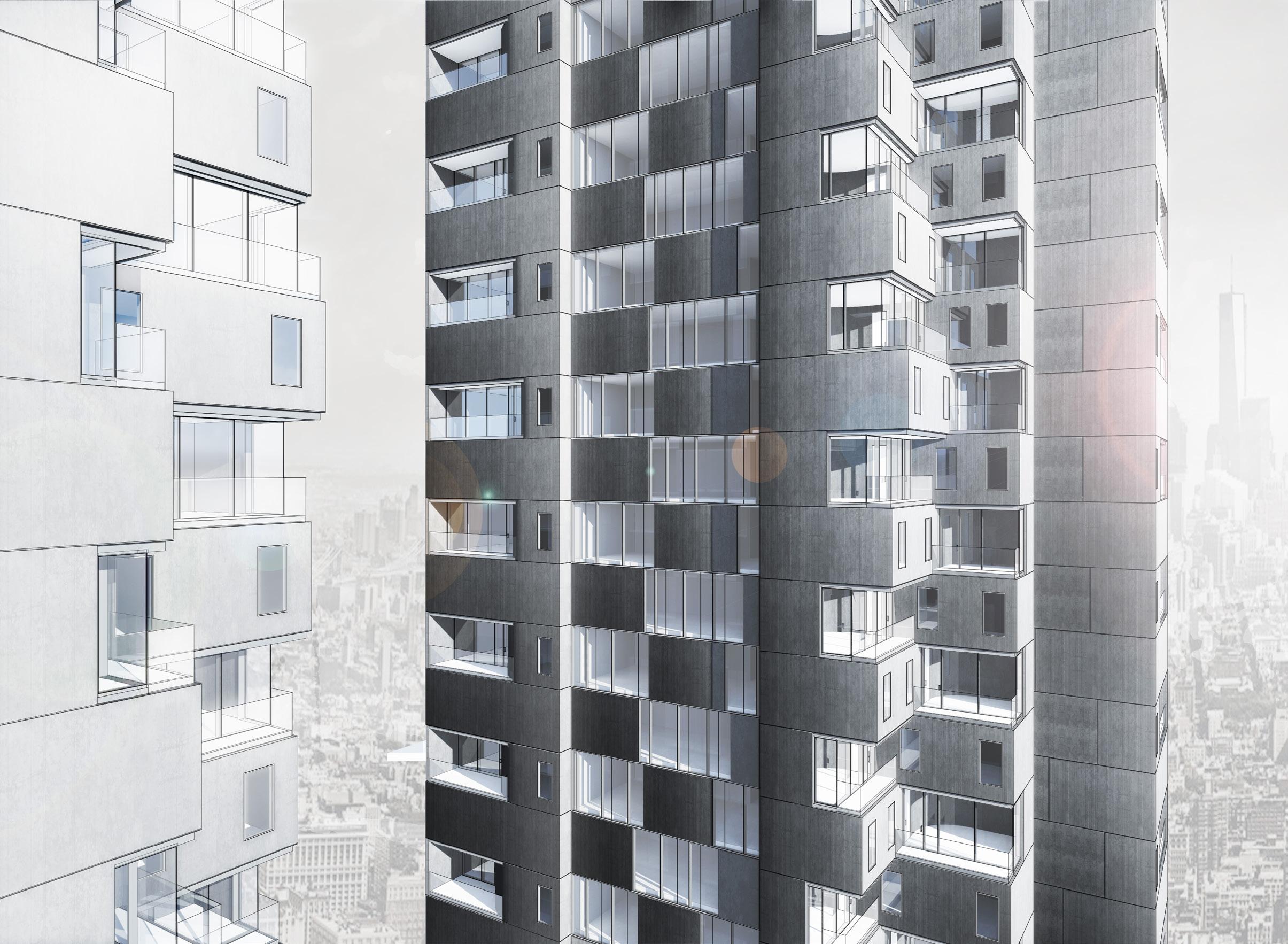
Owens Multi-Family Development in New York Architecture + Interior Design / 34 Beds / Common / Built / Phases Involved: SD, DD, CD, CA Unit 1A/1B/1C BR 1 88 SF 9' 8" x 8' 3" Living Room / Kitchen BR 2 85 SF 8' 6" x 7' 10" BR 3 97 SF 10' 6" x 7' 10" BA 1 Unit 2C/3C/4C Living Room / Kitchen BR 1 89 SF 11' 2" x 8' 0" BR 2 101 SF 11' 9" x 9' 4" BA 1 Unit 2B/3B/4B BR 1 81 SF 8' 8" x 8' 7" BR 2 93 SF 11' 0" x 8' 5" BR 3 91 SF 10' 5" x 8' 2" BR 4 108 SF 13' 6" x 8' 0" BR 5 123 SF 11' 9" x 9' 9" BA 1 BA 2 BR 6 81 SF 12' 0" x 8' 0" Living Room / Kitchen © Common 2021 Not for Distribution. For Design Intent Only. As indicated Second / Third / Fourth Floor 529 Monroe Street, Brooklyn, NY, 11221 3/16"=1' 0" 0 2' 4' 8' Typical Floor Plan
Common
YOU CHIA LAI / WORK SAMPLE 8 ID 3.2 01 Varies, Contractor to Verify 2'-11" 1" EQ. 2'-6" EQ. 2'-1" 3'-6" 2'-10" 1'-6" 1'-6" VIF 2'-6" 2'-0" VIF 8'-5" CLR. CLR. CLR. (D.W.) VIF AP-01a AP-03 AP-02 Pull-out Trash Bin ID 3.0 05 03 Line of Upper Cabinet above Line of Smoke Barrier above CL to Stove Align 0"
EQ. 3 4 3'-0" 2'-0" 3'-9" +/9'-9" VIF 1'-0" EQ. EQ. Line of Cabinet Compartment below Varies, Contractor to Verify 3'-0" VIF 2'-6" EQ. 2'-1" AP-04 Line of Counter below (M.W.) VIF CLR. REF. 2'-1" 9" 1'-3" Contractor to verify minimum clearance for REF. door operation per manufacturer's Instruction 1'-3" CL to Cabinet Varies, Contractor to Verify EQ. Align with Edge of Stove below Align with Edge of Stove below +42 G +42 G +42 G ID 3.0 04 Typ. ID 3.2 05 Typ. ID 3.2 06 Typ. ID 3.2 04 ID 3.1 04 SIM. PL 01 AP-05 2'-1" 3'-0" 2'-10" 16'-0 2 " +/3'-0" 7" 2'-0" 2'-1" 11'-4 2 " 11'-1 2 " 11'-1 2 " 19'-0 2 " VIF 2'-11" VIF 1" 16'-0 2 " EQ. 2'-6" EQ. 19'-0 2 " VIF Contractor to verify minimum clearance for REF. door operation per manufacturer's Instruction 7'-11" AP-01a AP-03 ID 3.0 08 10 Line of Upper Cabiner above Line of Smoke Barrier above Align (D.W.) AP-02 Pull-out Trash Bin Line of Cabinet Compartment below 2'-1" 9" CLR. CLR. 1'-3" 3'-0" VIF 16'-0 2 " +/EQ. 2'-6" EQ. 19'-0 2 " VIF CLR. AP-04 (M.W.) 2'-1" 1'-3" Line of Counter below Line of Smoke Barrier above REF. Align with Edge of Stove below Align with Edge of Stove below ID 3.1 07 MIR ID 3.1 04 +42 G +42 G ID 3.0 09 ID 3.2 03 Typ. SIM. PL 01a AP-05a 15'-8 4 VIF 3'-0 3 4 +/1'-0" 9'-9" VIF Contractor to verify minimum vertical clearance for REF. per manufacturer's Instruction AP-01a ID 3.2 06 Typ. AP-02 (D.W.) Pull-out Trash Bin 2'-1" 1'-3" 2'-1" 2'-0" EQ. 2'-1" 1'-412 2'-1" EQ. 2'-6" EQ. 1" 2'-11" 8'-414 19'-2 2 " VIF CLR. CLR. Contractor to verify minimum clearance for REF. door operation per manufacturer's Instruction AP-01a AP-03 REF. Line of Upper Cabinet above Line of Smoke Barrier above 2'-0" 2'-0" 2'-1" ID 3.0 13 14 +42 +42 G G ID 3.2 02 ID 3.2 03 ID 3.2 06 ID 3.2 05 SIM PL 01a AP-05a 2'-10 3 4 " +/2'-6" 3'-0" VIF 19'-2 2 " VIF CLR. AP-04 (M.W.) 2'-1" 1'-3" Align with Edge of Stove below Align with Edge of Stove below Line of Counter below 15'-8 4 VIF 2'-0 3 4 " +/8'-9" VIF Contractor to verify minimum vertical clearance for REF. per manufacturer's Instruction 1'-0" AP-01a ID 3.2 06 Scale: 1/2" = 1'-0" Unit 1A, 1B(MIR.), 2A, 3A, 4A Kitchen Upper Cabinet Enlarged Plan 02 Scale: 1/2" = 1'-0" Unit 1A, 1B(MIR.), 2A, 3A, 4A Kitchen Enlarged Plan 01 Scale: 1/2" = 1'-0" Unit 1A, 1B(MIR.), 2A, 03 Scale: 1/2" = 1'-0" Unit 2C, 3C, 4C Kitchen Enlarged Plan 06 Scale: 1/2" = 1'-0" Unit 2C, 3C, 4C Kitchen Upper Cabinet Enlarged Plan 07 Scale: 1/2" = 1'-0" Unit 2C, 3C, 4C Kitchen 08 Scale: 1/2" = 1'-0" Unit 1C & 1D Kitchen Enlarged Plan 11 Scale: 1/2" = 1'-0" Unit 1C & 1D Kitchen Enlarged Upper Cabinet Plan 12 Scale: 1/2" = 1'-0" Unit 1C & 1D Kitchen Interior 13 2'-10" 1'-6" 1'-6" VIF 2'-6" 2'-0" VIF 8'-5" CLR. CLR. (D.W.) AP-02 Pull-out Trash Bin 05 CL to Stove 0" (2) EQ. 3 4 3'-0" 2'-0" 3'-9" +/9'-9" VIF 1'-0" EQ. EQ. 15'-8 4 " VIF 3'-0 3 4 " +/1'-0" 9'-9" VIF 4" (2) EQ. EQ. EQ. 3'-0" below Varies, Contractor to Verify 3'-0" VIF 2'-6" EQ. 2'-1" AP-04 Line of Counter below (M.W.) VIF CLR. 2'-1" 9" Contractor to verify minimum vertical clearance for REF. per manufacturer's Instruction
CL to Cabinet CL to Cabinet Varies, Contractor to Verify EQ. Align with Edge of
below Align with Edge of Stove below +42 G ID 3.0 04 ID 3.2 05 Typ. ID 3.2 04 ID 3.2 06 ID
01
1'-5
4
Align Tile
SIM. PL 01 WL
AP-05
2'-1"
EQ.
EQ.
VIF Contractor to
manufacturer's
AP-01a AP-03 ID
08 of Upper Cabiner above of Smoke Barrier above of Cabinet Compartment
Line
below of Smoke Barrier above REF. Align with Edge of Stove below Align with Edge of Stove below +42 G +42 G SIM. 15'-8 4 VIF 3'-0 3 4 +/1'-0" 9'-9" VIF Contractor to verify minimum vertical clearance for REF. per manufacturer's Instruction 4" (2) EQ. 3 4 3'-0" 2'-0" 3'-9" +/9'-9" VIF 1'-0" EQ. EQ. AP-03 AP-04 AP-01a CL to Cabinet CL to Cabinet Tile Grount Joint 1'-5 1 4 " VIF Align ID 3.2 06 Typ. ID 3.2 01 Typ. WL 01 WL 02 3'-0" 3'-0" 1'-3" 2'-1" 2'-1" EQ. 2'-6" EQ. 1" 2'-11" 19'-2 2 " VIF CLR. Contractor to verify minimum clearance for REF. door operation per manufacturer's Instruction REF. 2'-1" +42 +42 G G ID 3.2 02 ID 3.2 06 2'-10 3 4 " +/2'-6" 3'-0" VIF 19'-2 2 " VIF CLR. AP-04 (M.W.) 2'-1" 1'-3" Align with Edge of Stove below Align with Edge of Stove below Line of Counter below AP-04 15'-8 4 VIF 2'-0 3 4 " +/8'-9" VIF Contractor to verify minimum vertical clearance for REF. per manufacturer's Instruction 1'-0" AP-03 4" 2'-8" 3'-0" 2'-0" 2'-9" +/1'-0" 8'-9" VIF AP-01a CL to Cabinet CL EQ. EQ. Tile Grount Joint 1'-5 1 4 " VIF Align ID 3.2 06 ID 3.2 01 ID 3.2 02 WL 01 WL 02 3'-0" 8'-9" VIF 1'-0" Scale: 1/2" = 1'-0" Unit 1A, 1B(MIR.), 2A, 3A, 4A Kitchen Upper Cabinet Enlarged Plan 02 Scale: 1/2" = 1'-0" Unit 1A, 1B(MIR.), 2A, 3A, 4A Kitchen Interior Elevation 03 05 04 Scale: 1/2" = 1'-0" Unit 2C, 3C, 4C Kitchen Upper Cabinet Enlarged Plan 07 Scale: 1/2" = 1'-0" Unit 2C, 3C, 4C Kitchen Interior Elevation 08 10 09 Scale: 1/2" = 1'-0" Unit 1C & 1D Kitchen Enlarged Upper Cabinet Plan 12 Scale: 1/2" = 1'-0" Unit 1C & 1D Kitchen Interior Elevation 13 14 Sample Kitchen Enlarged Plan Sample Kitchen Enlarged Elevation
(2)
AP-03 AP-04 AP-01a 1'-3"
Stove
3.2
Typ. Typ.
1
VIF
Grount Joint
01 WL 02
3'-0"
3'-0" 2'-11" VIF 1" 16'-0 2 "
2'-6"
19'-0 2 "
verify minimum clearance for REF. door operation per
Instruction
3.0
CLR. 1'-3" 3'-0" VIF 16'-0 2 " +/EQ. 2'-6" EQ. 19'-0 2 " VIF CLR. AP-04 (M.W.) 2'-1" 1'-3"
of Counter

Common Bosco

Multi-Family Development in Berkeley

Architectural Consultation + Interior Design | 60 Beds | Common | Built | Phases Involved: SD

Lobby
Finish Floor Plan
4" 2'-10"
3'-0"
6'-8" C L 9'-3" VIF
Polished Concrete Floor Wood Veneer Wall Panel Eggshell White Paint Black Decorated Lighting Fixture / Hardware Grey Laminate Pntd. White Baseboard Bosco 12
4" 2'-10" 2'-0"
3'-0"
C L 9'-3" VIF
Polished Concrete Floor Wood Veneer Wall Panel Eggshell White Paint Black Decorated Lighting Fixture / Hardware Grey Laminate Pntd. White Baseboard Material Palette & Proposed Laundry Lounge Elevation
Laundry Louge - 3D
2'-0" 1'-0" 1'-0"
1'-6"
1'-0"
Laundry Louge - Plans + Elevations
1'-0" 1'-0"
1'-6" 6'-8"
1'-0"

Hotel Saint George

Design of a Boutique Hotel in Marfa, Texas Architecture | 24,600 sqft | Carlos Jiménez Studio | Built | Phases Involved: SD, DD

Hotel Lobby Iso

YOU CHIA LAI / WORK SAMPLE 11

Room Type C Room Type D

YOU CHIA LAI / WORK SAMPLE 12
S HIGHLAND AVE NOTE: Distance not to scale E E L P A S O S T S O U T H E R N P A C I F I C R A I L R O A N
Hotel Room Type Test Fit Typical Hotel Floor Plan 14’-0” 14’-0” 14’-0” 14’-0” 14’-0” 14’-0” 14’-0” 14’-0” 20’-2” 20’-2” 14’-0” 14’-0” 14’-0” 14’-0” 34’-9” 32’-2” 32’-2” 18’-4” 18’-4” 18’-4” 34’-9” 14’-0” 14’-0” 14’-0” 14’-0” property line
Room Type A Room Type B

RXR Farm Stand

Design of a Farm Stand and Retail Building in Mara, Texas Architecture | 20,625 sqft | Carlos Jiménez Studio | Built | Phases Involved: SD, DD

YOU CHIA LAI / WORK SAMPLE 13
YOU CHIA LAI / WORK SAMPLE 14 N
Floor Plan
1'-0" 4'-0" Height Wall D C
6'-5" 6'-0"
4'-0" 9'-0" 4'-10" 8'-8" 10'-6" 4'-10" 2'-0" 34'-2" 466'-3" 5'-0" 20'-0"
200'0" 23'-10" 25'-0" 25'-0" 5'-0" 25'-0" 25'0" 25'-0" 25'-0" 23'-10" 1'-2" 5'-0" 16'-0" 40'-0" 16'-0" 3'-4" 22'-0" 30'-8" 12'-0"
12'-0" 48'-0" 12'-0" 4'-0"
1'-6" 37'-4" 23'-0" 16'-0" 50'-0" 75'-0" 75'-0" 1'-8" 22'-0" 40'-0"
20'-5" 20'-5" 11'-6" 11'-2" 12'-0" 6'-6" Hallway Bar E D C B A Skylight Above UP Event Space (enclosed) 9 8 7 6 5 4 3 2 1 2 4 5 7 9 Outdoor area (covered) Green Room 2 2 1 1 1 1 1 1 A A 1 1 10'-0" 10'-0" 1
Floor Plan DN M W MECH. / STORAGE KITCHEN MECHANICAL E A 1 2 3 4 5 6 West Elevation 10'-0" 7’-0” eq. eq. 13’6” 12 3 eq. eq. eq. 35’ -0” eq.
Ground
6'-5" 4'-0" 6'-5" 4'-0" 53'-2"
4'-0" 6'-5" 6'-5" 10'-0" 10'-0"
6'-5" 18'-6" 4'-0" 4'-0"
17'-6" 17'-6" 20'-0" 75'-0"
1'-2"
1'-6"
16'-0"
Second

Crowley Theater

YOU CHIA LAI / WORK SAMPLE 15 F.F.L. exposed steel ties 4” 8” C GIRT window trim w/ building packages steel beam 24 galv. MBCI 7.2 panel steel beam 24 galv. MBC1 7.2 panel 4ft o.c. 8” purlin insulation 4ft o.c. 8” girt Additional Base Angle In line with ISF of Girts or use 8” C as base insulation outside faces of column As built dimension 5/8” Gypsum board 4” As built dimension girt outside faces of column window trim w/ building packages steel beam 4ft o.c. 8” girt 8” C girt slope sill away from window 24 galv. MBCI 7.2 panel R-30 batt insulation 24 galv. MBCI 7.2 panel perforated metal ceiling panel fastened to bottom of purlin 4ft o.c. 8” purlin Additional Base Angle In line with ISF of Girts or use 8” C as base F.F.L. 5/8” Gypsum board Align 5/8” Gypsum board
|
Addition Design of a Theater Addition in Marfa, Texas (under construction) Architecture | 4,000 sqft | Carlos Jiménez Studio | Under Construction
Phases Involved: DD, CD
YOU CHIA LAI / WORK SAMPLE 16 RF. New Concrete Pad MULTI-PURPOSE ROOM VESTIBULE / ENTRY A-3.2 3 A-3.1 3 A-4.2 1 A-4.1 1 A-5.2 2 A-3.2 2,2a A-3.2 1 A Men Women 105 103 102 104 B EXISTING THEATER MECH. STOR. A-3.2 4 A-3.1 1 A-3.1 2 new tree existing opening (verify location) existing opening (verify location) Align 11’-0” 20’-4” 32’-0” 35’-0” 6” 35’-0” 21’-0” 6” 64.5 12’-2” 3’-0” 8’-7” 20’-4” 20’-4” eq. eq. 20’-4” 4’-9” 5’-2” 8’-0” 7’-2” 50’-0” 130’-2” align with length of existing theater, verify) 7’-1” 4’-5” 9’-0” 2’-6” 7’-0” 22’-9” 3’-0” 101 101 64.5 c c A-5.2 3 2’-8”clear 107 106 Ground Floor Plan 12” O.C. standing seam metal panels (roofing / wall) exposed steel I-beam (galvanized) A F.F.L 27’-0” 19’-0” 1 2 3 4 5 6 7 8 20’-0” 10’-0” 20’-0” 20’-0” 20’-0” 19’-0” 10’-0” North Elevation
YOU CHIA LAI / WORK SAMPLE 17 KR Studio Single Family House in Upstate NY Architecture | 2,500 sqft | LEVENBETTS | Built | Phases Involved: DD, CD, CA 02 A501 01 A501 01 Sliding Door Section Detail @ Door 102 (3) 1 3/4" x 11 7/8" LVL Header 5/8" Pntd GWB 25 Gauge 7/8" Furring Strip on 1x Wood Battem Sound Isolation Clip 2x3 Wood Stud 16" O.C Sliding Door 3/4"Wood Floor 1/4" Soundproofing Underlayment 2x3 PT Wood Batten 3" Mineral Wool Continuous Insulation Board High-temp Waterproof Underlayment Vapor Permeable Air Barrier Metal Flashing Retractable Screen 14"/360 TJI PT Rim Joist Concrete Foundation Wall See A005 for detail Metal Flashing 1/2" Plywood Sheathing Vapor Permeable Air Barrier 1/2" Plywood Sheathing 8x6x1/2" Steel Angle Bolted on LVL w/ 3/4" Dia Through Bolt 2'-0" O.C Staggered Line of Wood Siding Beyond 3" Mineral Wool Continuous Insulation Board 3/8" Aluminum Plate Bolted to Stl Frame 3/4" Plywood Subfloor Pntd Corner Bead 2x6 Wood Stud 16" O.C Mineral Wool Batt Insulation 1x4 Wood Siding w/ 1/8" Gap on 2x Wood Battens Insect Screen 3 1/2"x3 1/2"x1/4" Alum Angle High-temp Water-proof Underlayment 5/4" x 4" Decking Boards w/ 1/8" Gap to Match Siding on 1x Wood Battens 2x8 Deck Framing High-temp Water-proof Underlayment Align Align 02 Sliding Door (3) 1 3/4" x 11 7/8" LVL Header 5/8" Pntd GWB 25 Gauge 7/8" Furring Strip on 1x Wood Battem Sound Isolation Clip 2x3 Wood Stud 16" 3/4"Wood Floor 1/4" Soundproofing Underlayment 14"/360 TJI PT Rim Joist Concrete Foundation See A005 for detail 1/2" Plywood Sheathing 3/4" Plywood Subfloor Pntd Corner Bead 2x6 Wood Stud 16" Mineral Wool Batt Pntd Removable MDF Panel on Z-Clip & Steel Angle See A531 for Detail Sliding Pocket Door 3x3x1/4" Stl Angle Welded to 8x6x1/2" Stl Angle 4" Long @ 4'-0" O.C w/ (1) 3/4" Bolt through Alum w/ Neoprene Washer 4x4x1/4 Stl Angle Rib 3 1/2" 1/2" Alum Threshold on 1/4" Alum bed plate B.O Door Header +7'-4" T.O Fl Framing +0'-0" B.O Door Header +7'-4" T.O Fl Framing +0'-0" 3/8" Aluminum Plate Bolted to Stl Frame High-temp Water-proof Underlayment EQ B 2x1.25x1/4" Stl Angle 3/4" Countersunk S.S Bolt w/ Neoprene Washer Typ T.O Deck Framing +0'-1/2" 4 2 A Aluminum Block Grind and Polish Smooth to Blend w/ Alum Plate 02 A505 1 1/2" 5/8" Countersunk S.S Screw w/ Neoprene Washer Typ EQ B EQ B 1 1/2" 1 1/2" 6" EQ A EQ A 8" 5/8" Countersunk S.S Screw w/ Neoprene Washer Typ 2x1/4" Stl Flat Bar Soundproofing Underlayment
YOU CHIA LAI / WORK SAMPLE 18
View from Southeast View from North

S-A House

Single Family House in Upstate NY Architecture | 2,700 sqft | LEVENBETTS | Built | Phases Involved: SD, CD, CA

YOU CHIA LAI / WORK SAMPLE 19
Master Bedroom 101 Master Bath 102 Guest Bath 104 Guest Bedroom 105 Hallway 108 Kitchen 112 Dining Room 111 Living Room 110 West Porch 114 South Porch 115 VECTORWORKS EDUCATIONAL VERSION
YOU CHIA LAI / WORK SAMPLE 20 01 House : Typical Wall Section Scale: 3/4" = 1'-0" Pntd GWB TJI Rafters Mineral Wool Tapered Insulation Board (R-8) Mineral Wool Cavity Batt Insulation (R-30) Vapor Permeable Air Barrier on Plywood Sheathing T/ Fin House Slab +0'-4 1/4" T/ Patio Slab +0'-2 1/2" B/ Footing -1'-7 3/4" T/ Structural Slab 0'-0" B/ Conc Stub Wall -2'-7 3/4" Mineral Wool Cavity Batt Insulation (R-23) 2x6 Wood Stud Mineral Wool Continuous Insulation Board (R-8) Vapor Permeable Air Barrier on Plywood Sheathing Cement Board Cladding Insulated Concrete Form R-23) Underslab Insulation (R-8) Vapor Barrier Concrete Stub Wall on Existing Rock on Site Radon Gas Mitigation Pipe around Footing Finish Concrete Slab w/ Radiant Heat Tubes 6" 4" Structural Concrete Slab Existing Rock on Site Gutter 6" Concrete Footing Pntd GWB 2x6 Floor Framing 2x6 Wood Stud Mineral Wool Continuous Insulation Board (R-8) 2x6 Roof Framing Mineral Wool Cavity Batt Insulation (R-23) Vapor Permeable Air Barrier on Plywood Sheathing Mineral Wool Tapered Insulation Board (R-8) Live Plant on Rubber Roofing Gutter Rubber Roofing Exterior Interior Exterior Interior 1'-0" 02 A321 Footing Drain
YOU CHIA LAI / WORK SAMPLE 21
YOU CHIA LAI / WORK SAMPLE 22 350E62
LEVENBETTS 350E62 UP UP UP Bedroom 111 Bedroom 108 Mid Platform 109 WC 110 Living Room 108 Balcony 105 Living Room & Dining Room 104 Closet 107 Bathroom 106 Kitchenette 102 Closet 103 Closet 112 Storage Pull-out Bed Frame Polycarbonate Wall VECTORWORKS EDUCATIONAL VERSION VECTORWORKS EDUCATIONAL VERSION
Apartment Renovation in New York City Architecture | 750 sqft | LEVENBETTS | Not Built | Phases Involved: SD, DD, CD Apartment Floor Plan
YOU CHIA LAI / WORK SAMPLE 23
Wood Platform Structure Isometric Drawing
7'-0" 11'-4" 12'-9" LEVENBETTS

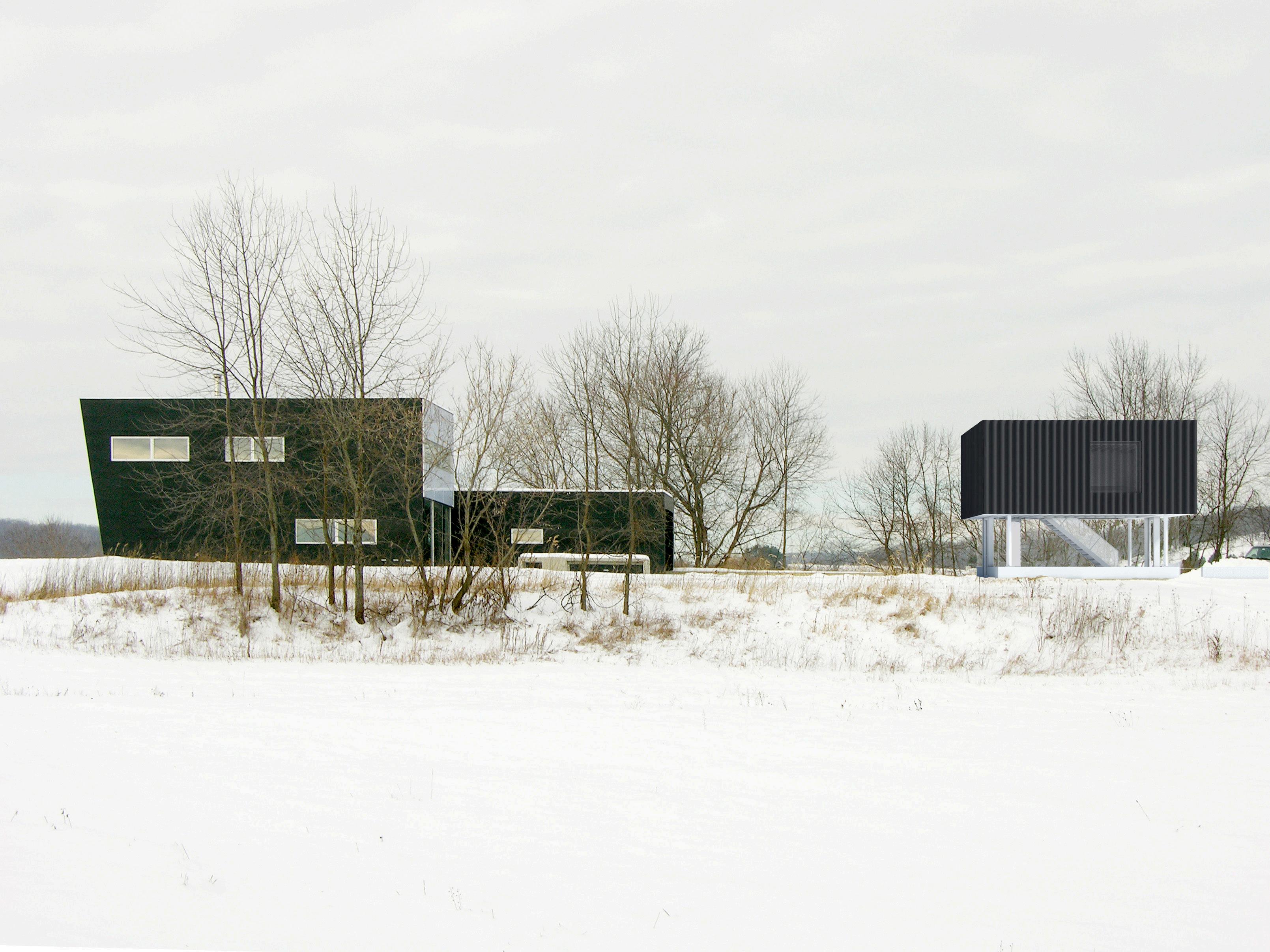
CC01 Pool House

Pool House in Upstate NY

Architecture | 700 sqft | LEVENBETTS | Not Built | Phases Involved: SD, DD, CD

YOU CHIA LAI / WORK SAMPLE 24
EDUCATIONAL VERSION Existing House New Addition
VECTORWORKS
YOU CHIA LAI / WORK SAMPLE 25
House Pocket Door Plan Detail House Fixed Glass Section Detail Pntd Corrugated Alum Panel on 1x Wood Batten 2" Continuous Mineral Wool Insulation Board 5/8" Pntd GWB on 2X Wood Batten 2X6 Wood Stud 16" O.C Mineral Wool Batt Insulation 1/2" Plywood Sheathing Vapor Permeable Air Barrier 2" Mineral Wool Insulation Board Line of Siding Vent Below Pntd Corrugated Metal Siding on 1x Wood Siding Overlap of Metal Siding dependent on Material Length 01 Plan Detail @ Guest House Window 201 02 Plan Detail @ Guest House Siding Typ Pntd Exposed Roof Joist 3/4" Wood Fl 1/2" Tempered Glass Sliding Glass Track 5/8" Pntd GWB on 2x Wood Batten w/ Angle Bead 2X6 Wood Stud 16" O.C Mineral Wool Batt Insulation 1/2" Plywood Sheathing Vapor Permeable Air Barrier High Temperature Waterproof underlayment 2" Mineral Wool Insulation Board Line of Siding Vent Below Perf Pntd Corrugated Metal Siding on 1x Wood Batten Thermally Broken Alum Frame Door 1" Removable MDF Fastened on Stl Angle 2X4 Wood Stud for Pocket Framing 16" O.C Mineral Wool Batt Insulation 1/2" Plywood Sheathing Vapor Permeable Air Barrier High Temperature Waterproof underlayment 2" Mineral Wool Insulation Board Line of Siding Vent below Perf Pntd Corrugated Metal Siding on 1x Wood Batten 1/8" Pntd Alum Pntd Alum Retractable Screen Retractable Screen Thermally Broken Alum Frame Door Align Align Portion of Perf Panel 3"x1.5"x.1/4" Stl Tube Retractable Screen 2"x7"x1/4" Custom Alum Angle Wood Blocking Line of Pntd Alum Plate Line of Thermally Broken Alum Window Frame below Countersunk Screw 1" CL 1" High Temperature Waterproof Underlayment 04 Section Detail @ Guest House First Floor Window Head 01 Section Detail @ Guest House Parapet Wall 07 Section Detail @ Guest House Stem Wall Typ Vapor Permeable Air Barrier Pntd Corrugated Alum Panel on 1x Wood Batten 1/2" Plywood Sheathing 2" Continuous Mineral Wool Insulation Board 2 x 6 Wood Stud 16" O.C Mineral Wool Batt Insulation Parapet Coping on Intermittent Blocking High Temperature Waterproof Underlayment 1/2" Plywood Sheathing Vapor Permeable Air Barrier Vapor Permeable Air Barrier Pntd Corrugated Alum Panel on 1x Wood Batten 1/2" Plywood Sheathing 2" Continuous Mineral Wool Insulation Board 2 x 6 Wood Stud 16" O.C Mineral Wool Batt Insulation 1/2" Z Reveal 5/8" Pntd GWB on 2x Wood Batten Wood Floor on 3/8" Soundproofing Underlayment Pntd Alum Panel 3/4" Plwd Subfloor Foam Closure Strip behind Siding Mineral Wool Batt Insulation Double Glazed Fixed Glass Panel 3" Mineral Wool Insulation Board @ Exteior of Foundation Wall Existing Concrete Slab W10x26 Pntd Stl Beam LED Strip Light 08 Plan Detail 14" x 6" x 3/8" Steel Bolt Plate 5 1/2" Dia.Pntd (2) 5/8” Diameter Anchors in Hy200 Double Glazed Fixed Glass Panel Existing Foundation Stem Wall Foam Closure Strip behind Siding Cor-A-Vent Siding Vent Cor-A-Vent Siding Vent 2x12 Pntd Floor Framing Cor-A-Vent Siding Vent 5/8" Cement Board w/ Troweled Cement 5 1/2" Dia Pntd Steel Column Pntd Alum Plate 3/8" Pntd Steel Base Plate 2 Pntd Alum Plate Thermally Broken Alum Window Frame 1" Non-Shrink Grout 2" Mineral Wool insulation Board (2) 5/8” Diameter Hilti Hit Anchors in Hy200 Epoxy Electrical Line Double Glazed Fixed Glass Panel Line of Thermally Alum Window 8" Line of Pntd Alum Countersunk Screw Line of Pntd Alum Countersunk Screw Line of Thermally Alum Window Electric Line Refrigerant Line Only @ North Wall 3 1/4" PT 2x4 Block 2" 5/8" Align
House Bathroom

Turn static files into dynamic content formats.

Create a flipbook
Issuu converts static files into: digital portfolios, online yearbooks, online catalogs, digital photo albums and more. Sign up and create your flipbook.