PIER 24: THESIS DESIGN BOOK GIANCARLO CANO SPRING 2022 5/13/22
TABLE OF CONTENTS
THESIS POSTION PAPER
PRECEDENT ANALYSIS
SITE ANALYSIS
ANALYSIS
PROGRAM
CONCEPT REVIEW PRELIMINARY REVIEW MID CRIT, REVIEW PIER 24: FINAL REVIEW POSITION PAPER ACKNOWLEDGMENT BIBLIOGRAPHY 8 14 60 102 108 120 150 168 206 210 214
THESIS POSITION PAPER
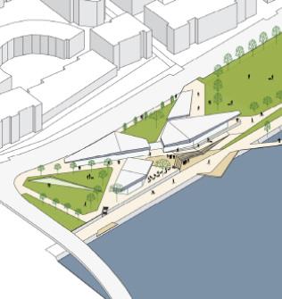
A place where the user could relax with the views of the water escaping the noise of vehicular activity. Through it a hidden gem, a park nestled out into a water front. Creating public engagement and activities through exterior uses or interior uses of the building.
Through the theory of ornamentation this building and its site would create such unique experiences. This method will inform how the building would sit on the site and how its façade could create a complex subtlety to it. It conveys how the building could blend with both the water front feature and the highway. The façades detailing as well as interiors would help achieve how the materiality of the building could become a unique experience architecturally. As well as the theory of structural expression. How the building could interact with the site. Also creating an elaborate experience.
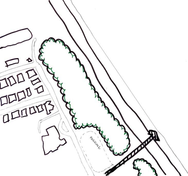
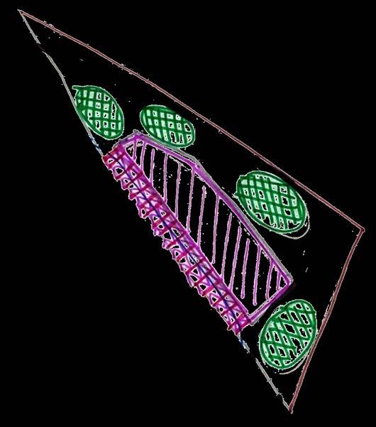
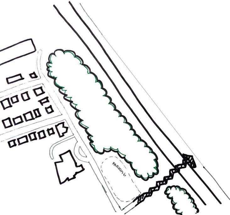
To create a project where the water front, highway, and vegetated area would be emphasized in connecting to the existing pedestrian walkway. This will branch a new connector piece from the residential side over the highway to the water front. A connector piece which would be considered as a land bridge.
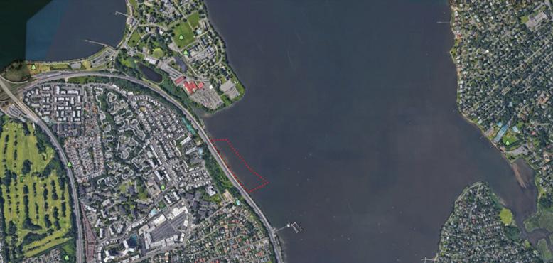
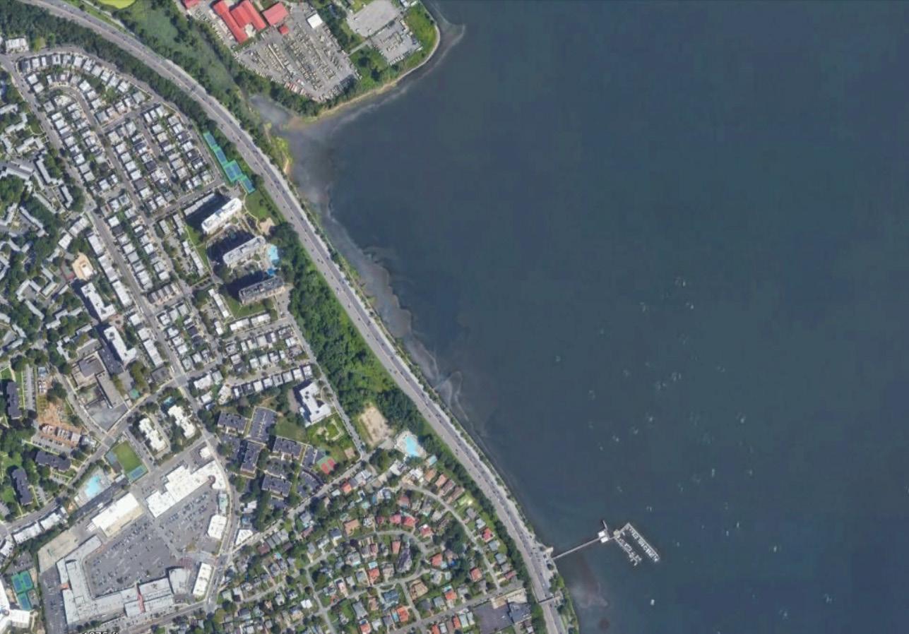
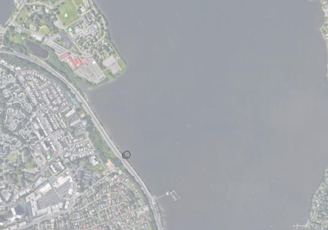
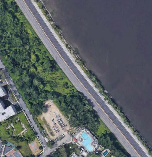
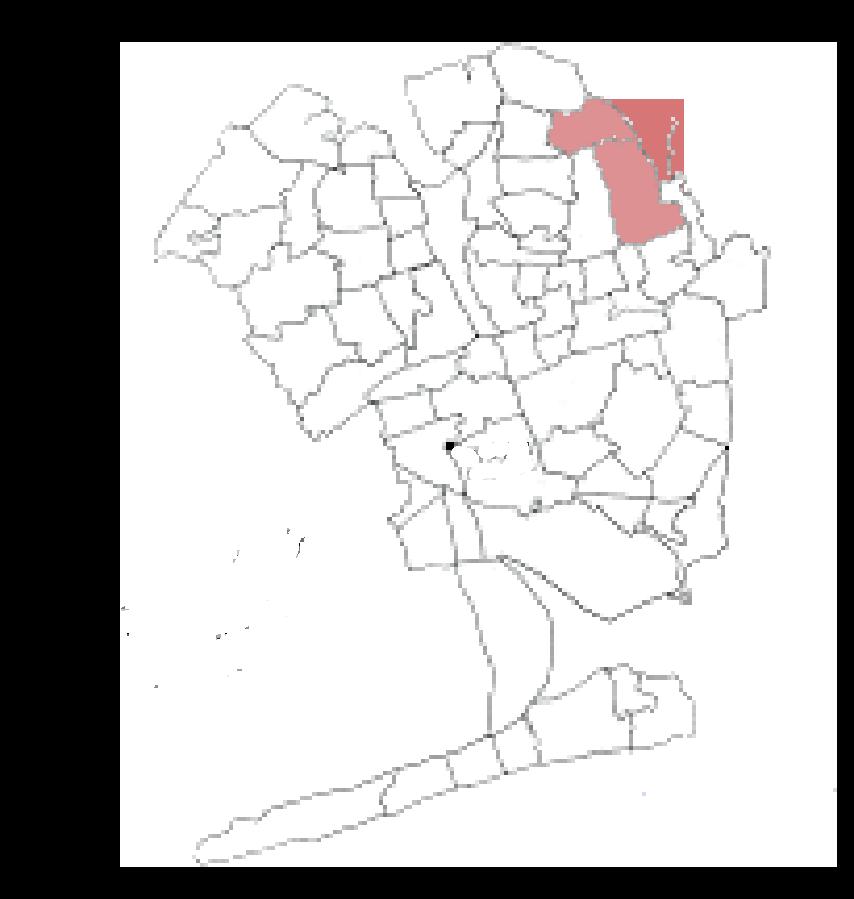
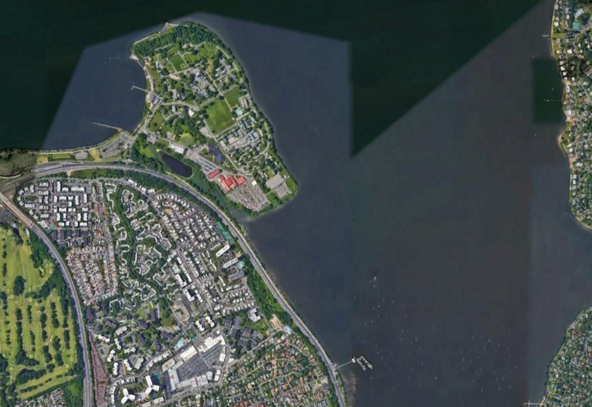
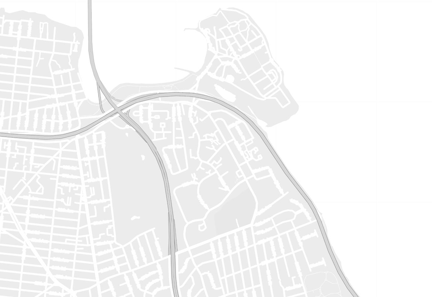
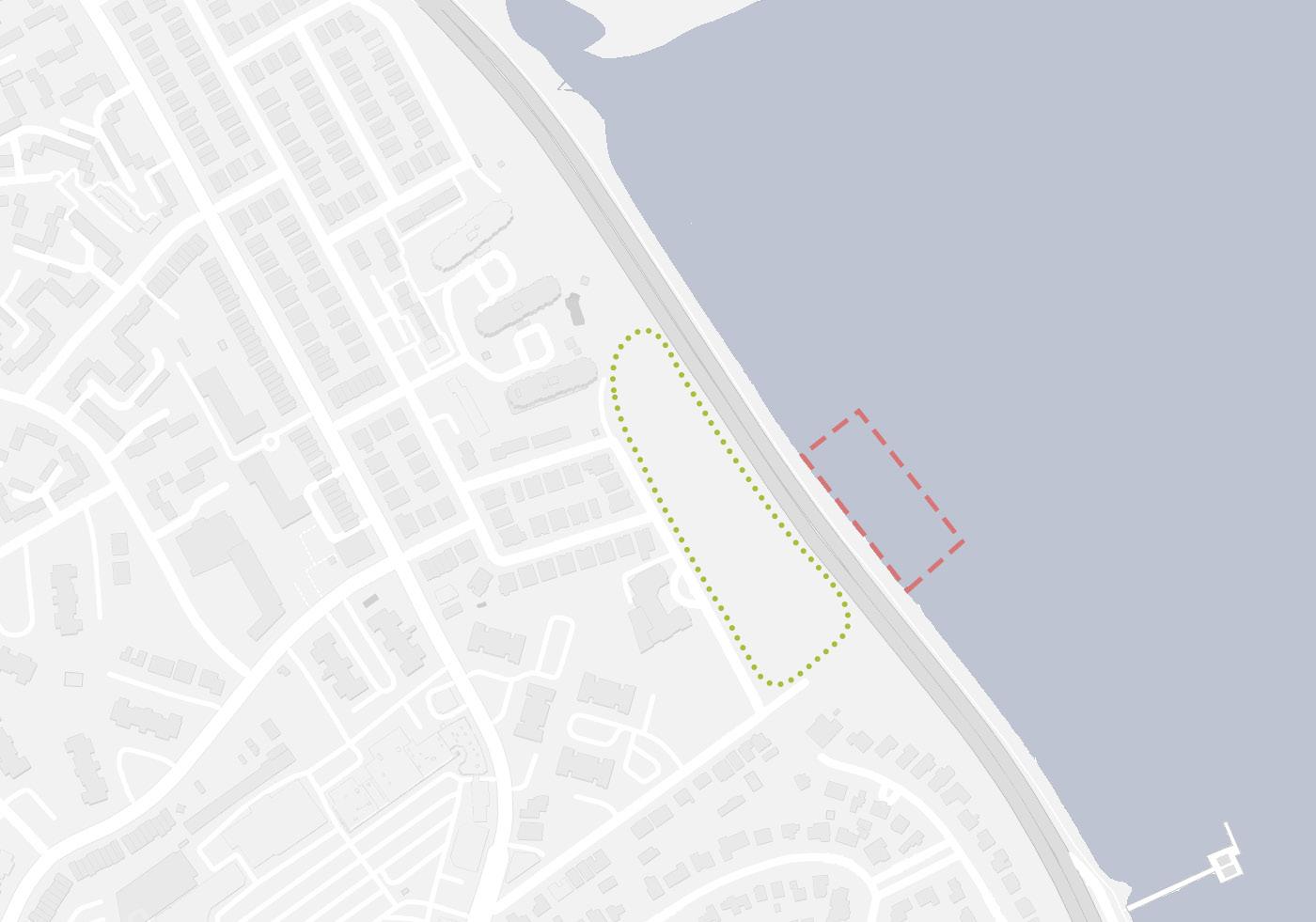
This proposal is to utilize this untouched bay (Long Island Sound) into my advantage. To create a structure that could reach into the water while creating interesting public space opportunities for shade and rest for people using the existing pedestrian path. This will also play a great opportunity to bridge over the highway which in hand connects both the residential side and the soon to be public facility. This would not only entice people living on other side of the high way but also users that park in the Fort Totten parking lot. The site is located in Bay-side, Queens, New York, along the cross island parkway. It would sit in between Fort Totten ( Military base/ Park) and the Bay-side Marina.
The challenge would be design a building that could relate to the site context through ornamentation and structural expression and trying to cohesively be able to design a connector element which become impactful to the site.
The buildings space and its orientation will leave a huge impact on how people would approach it and or use it. Setting scale would help soften how its placed on the site as well as how much open space there would be needed. Building v.s. open space.
The has a lot of potential. Creating a connector, designing a building and developing spaces indoor and out would emulsify a beautiful project.
6
THESIS POSITION PAPER
SITE MAP : BAYSIDE
7
SITE MAP : BAYSIDE
PRECEDENT ANALYSIS
ACTIVE/

COMMUNITY HUB
CREATIVE JUNGLE
VERSATILE PAVILION
TCDC KHON KAEN
PERGOLA LUOTUOWAN
LATTICE WOOD
SPRINGVALE COMMUNITY HUB
 MODULAR FRAME WORK
THE CONNECTION TO RHODES
ACTIVE HUB
ARCH WILD LIFE CROSSING HUNTERS POINT
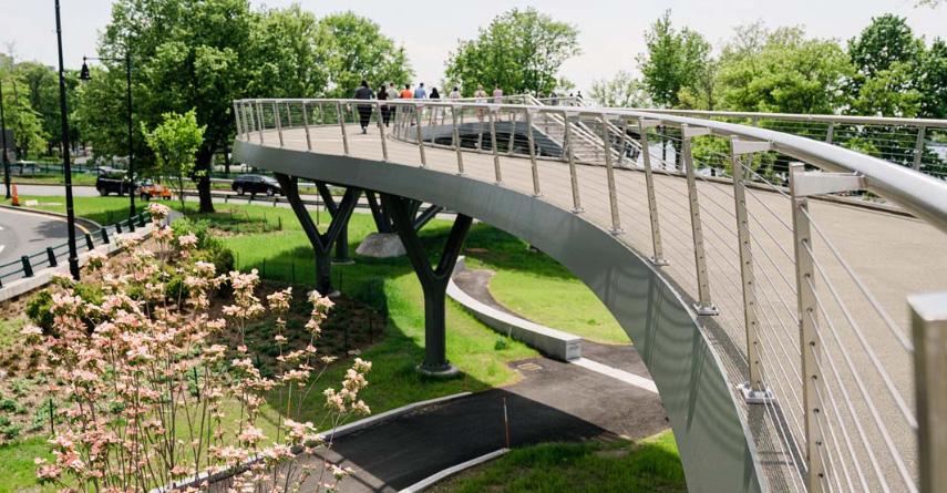
FRANCIS APPLETON BRIDGE
MODULAR FRAME WORK
THE CONNECTION TO RHODES
ACTIVE HUB
ARCH WILD LIFE CROSSING HUNTERS POINT
FRANCIS APPLETON BRIDGE
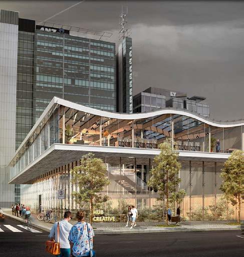
12 CREATIVE JUNGLE PROJECT: Creative Jungle ( competition ) PROJECT TYPE: Community Hub SIZE: NA LOCATION: Adelaide, Australia COST: NA DESIGNER: Lucas Monnerau and Thomas Leblond AWARDS: First place DATE: 2017 HTTPS://WORLDARCHITECTURE.ORG/ARCHITECTURE-NEWS/CVVPG/WINNERS_ANNOUNCED_FOR_CREATIVE_COMMUNITY_HUB_TO_DESIGN_AN_URBAN_CATALYST_IN_ADELAIDE.HTML INTERIOR AMPHITHEATER INTERIOR IMAGE
This project starts to look at where its located. The designer of the project illustrates that when zooming away from the general area this city is surrounded by a crown of vegetation.
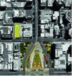
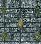
The next diagram zooms into the site further and pinpoints the five park/ green spaces which symmetrically creates this nestle of greenery for site relationship.
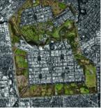
Now zooming into both parks which are closet to the site it then becomes a visualization of what could be developed since the site is near both green spaces represented.
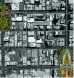
Calling out the site and focusing of the closest green plot. There then starts to create a story. A analysis on whats already there and what there could be in the future of the designing process.
Collecting from all these images I could get a sense of really looking at the site from multiple different views to help relate the area and the building in order to have a balance of continuity with one another. These site analysis drawings would help me in creating and developing outdoor spaces needed throughout my site since I could draw conclusions about what the residence have and do not have.
13
HTTPS://WORLDARCHITECTURE.ORG/ARCHITECTURE-NEWS/CVVPG/WINNERS_ANNOUNCED_FOR_CREATIVE_COMMUNITY_HUB_TO_DESIGN_AN_URBAN_CATALYST_IN_ADELAIDE.HTML SITE ANALYSIS 1 SITE ANALYSIS 2 SITE ANALYSIS 3 SITE ANALYSIS 4
DIAGRAMS
Its quite interesting how the building
take
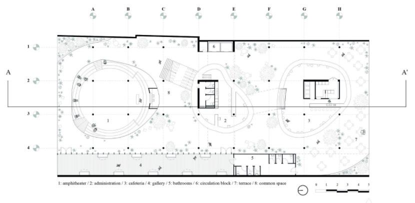
In plan the first floor of this project demonstrates great examples of creating interesting interior spaces. The use of organic shapes throughout these interactive areas help depict what events would be appropriate. There is also a sense of this easy flow through spaces because of bringing a lot of that vegetation into the building. This also softens many of the harsh materials inside a building.
Overall what becomes important to me through my development is what type of spaces would create a pooling of interaction just like the plan here.
As seen above this analysis starts
the interior and exterior
With
analysis I would take these
apply them to my own design. Showing the viewer how and why
14
starts to develop from an empty site to a process of elements to create a building form.
to
into consideration how each design idea starts to morph the building. It demonstrates this through
spaces.
all this
iterations of mass development and site development and
my building and site became to be. HTTPS://WORLDARCHITECTURE.ORG/ARCHITECTURE-NEWS/CVVPG/WINNERS_ANNOUNCED_FOR_CREATIVE_COMMUNITY_HUB_TO_DESIGN_AN_URBAN_CATALYST_IN_ADELAIDE.HTML FIRST FLOOR PROCESS
FIRST
Double heighted spaces create special environments
Digging into the ground to creates an amphitheaters
Ground level and second floor with terracing elements as well as the third level
At the third level the space is met with a waved steel roof
From the site analysis there are other garden nodes that are organized symmetrically The beams create a unified and consistent ornament throughout the buildings facade Bringing the outside in thought the use of green spaces which are designed for interactive purposes
Overhanging floors create a multiplex of floor plates in creating different functioning spaces
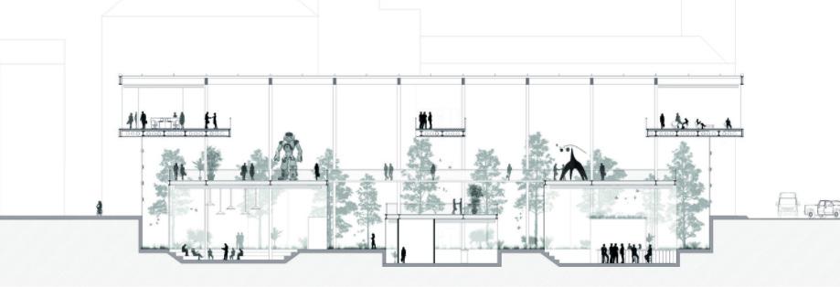
From the section above is developing spaces inside the building that create different functions and uses. The different floor and multiple heights throughout the building create a journey. Since the inside of the space is fuddled with a vast amount of vegetation it them becomes a forest like environment. Bleeding the outside into the inside. Also the double heighted space would help in creating a transparency from multiple levels to see what is occurring on other floors. These design features would help create what I’m trying to strive for. A cohesive design which allows indoor interaction and unique experiences.
15
HTTPS://WORLDARCHITECTURE.ORG/ARCHITECTURE-NEWS/CVVPG/WINNERS_ANNOUNCED_FOR_CREATIVE_COMMUNITY_HUB_TO_DESIGN_AN_URBAN_CATALYST_IN_ADELAIDE.HTML SECTION
FLOOR SECOND FLOOR THIRD FLOOR FOURTH FLOOR
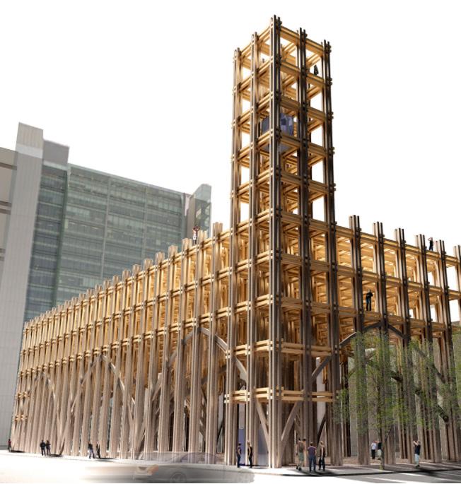
16 VERSITILE PAVILLION PROJECT: Versitile Pavilion ( competition ) PROJECT TYPE: Community Hub SIZE: NA LOCATION: Adelaide, Australia COST: NA DESIGNER: Banny Fabian and Sandoval salinas AWARDS: Honorable Mentioned DATE: 2017 HTTPS://ARCHITECTURECOMPETITIONS.COM/CREATIVEADELAIDE OUTLOOK DECK EXTERIOR NIGHT IMAGEARCH CEILING
FIRST FLOOR SECOND/ THIRD FLOOR
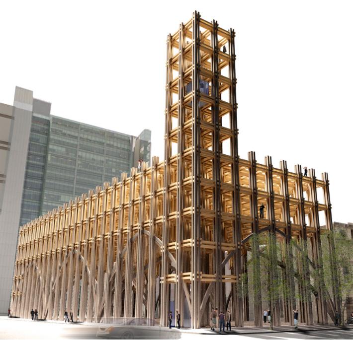
The first floor is described as being this public space. Out into the open and transparent. Its purpose is to invite the user and celebrate these beautiful Gothic arches.
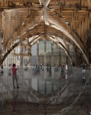
The openness feel to the first floor would help me in trying to design a space in my building where people are invited and feel amazed with the space. The lightness of a tall space would soften the structure.
The second/ third floor represents an emphasis on the structural modularity of the gridded floor plans. This entices the use of structural expression.
The ideas presented in the plan would help create an elaborate design of structural expression and ornamentation throughout the building. Also activity spaces.
FOURTH FLOOR
The fourth floor addresses the connecting feature from ground level to the upper floors. It eludes to this ceremonial stair tower that spirals up. Creating that tower feature on the building.
This grand stair case would help me in representing where the user could go and where they should circulate around the building. Color would also represent a boldness for “enter here”.
17
HTTPS://ARCHITECTURECOMPETITIONS.COM/CREATIVEADELAIDE
GROUND FLOOR INTERIOR
THIRD FLOOR INTERIOR
STAIR TOWER
CONNECTION DIAGRAMS
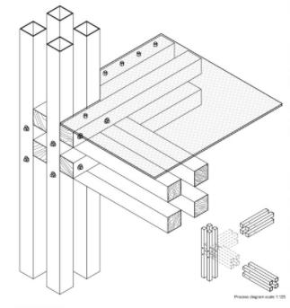
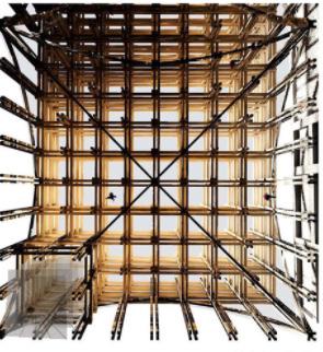
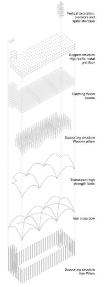
The axon construction diagram illustrates the process of how these members within the building are connected. It represents how many different design components were introduced into the structure of this Hub. From starting to the supporting iron structural pillars. To the iron cross bow arches. To a transparent fabric which wraps onto the iron cross arches. To the wooden lattice pillars. To the wooden beams. To the metal connections which join all the members of the structure. Lastly to a predominate vertical grand stair case. The structural connection diagrams gives a huge illustration on how these element within the axon construction are actually put together. The first diagram to the left represents how the building is connected to the ground. Showing how the wooden column is met with a steel plate, connected with rebar and stabilized by a foundation footing. The iron cross bow arches then are able to connect to the column. The second diagram shows how the floor plates are connected. The diagram of wood interlocking are all connected with steel connectors. It shows the column, beam and floor and how these peaces join.
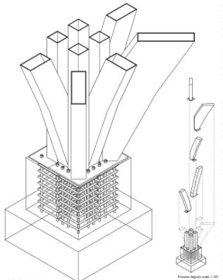
With all the information gathered going forward my intention is to diagram the structure and how the building would be constructed through this layering of elements. The zoomed in feature would help in representing some of the more important structural or technological elements within the project.
18
AXON CONSTRUCTION STRUCTURAL
HTTPS://ARCHITECTURECOMPETITIONS.COM/CREATIVEADELAIDE
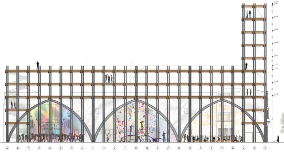
The elevation below represents a beautiful articulation of the spaces, and what occurs within the program. The elevation shows the elaborate beauty of structural expression. Organized modularity makes it easy to follow the project and helps fit specific spaces in an organized statement. The representation of the arches help the building open itself to the general public. It is seen below how these arches create a space where recreational or celebratory use would occur. The defining heights show how tall the building is with the use of scale figures. Lastly the stair tower, which becomes the primary focal point of the project. This tower becomes a landmark feature and a circulation feature. It becomes a tower for different views through every level and different activities.
Within this analysis I could represent many components of my design through section and elevation. The stair tower for example could create a precedent for creating a land mark element in my building or site in order to represent a node. The structural expression and ornamentation could be used to invite people to the site and building letting those element touch the ground. Also the use of spaces on each floor would help create this sense of exploration through spaces.
19 ELEVATION HTTPS://ARCHITECTURECOMPETITIONS.COM/CREATIVEADELAIDE
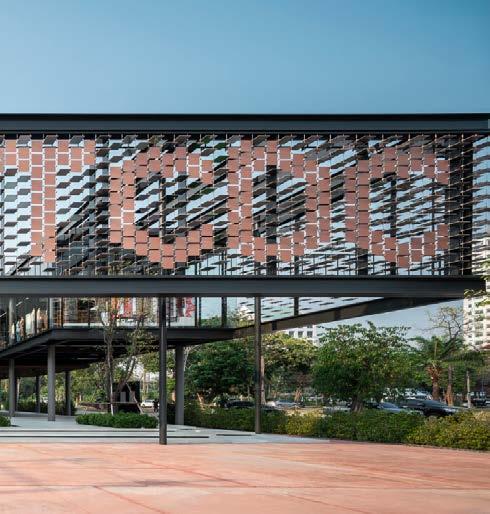
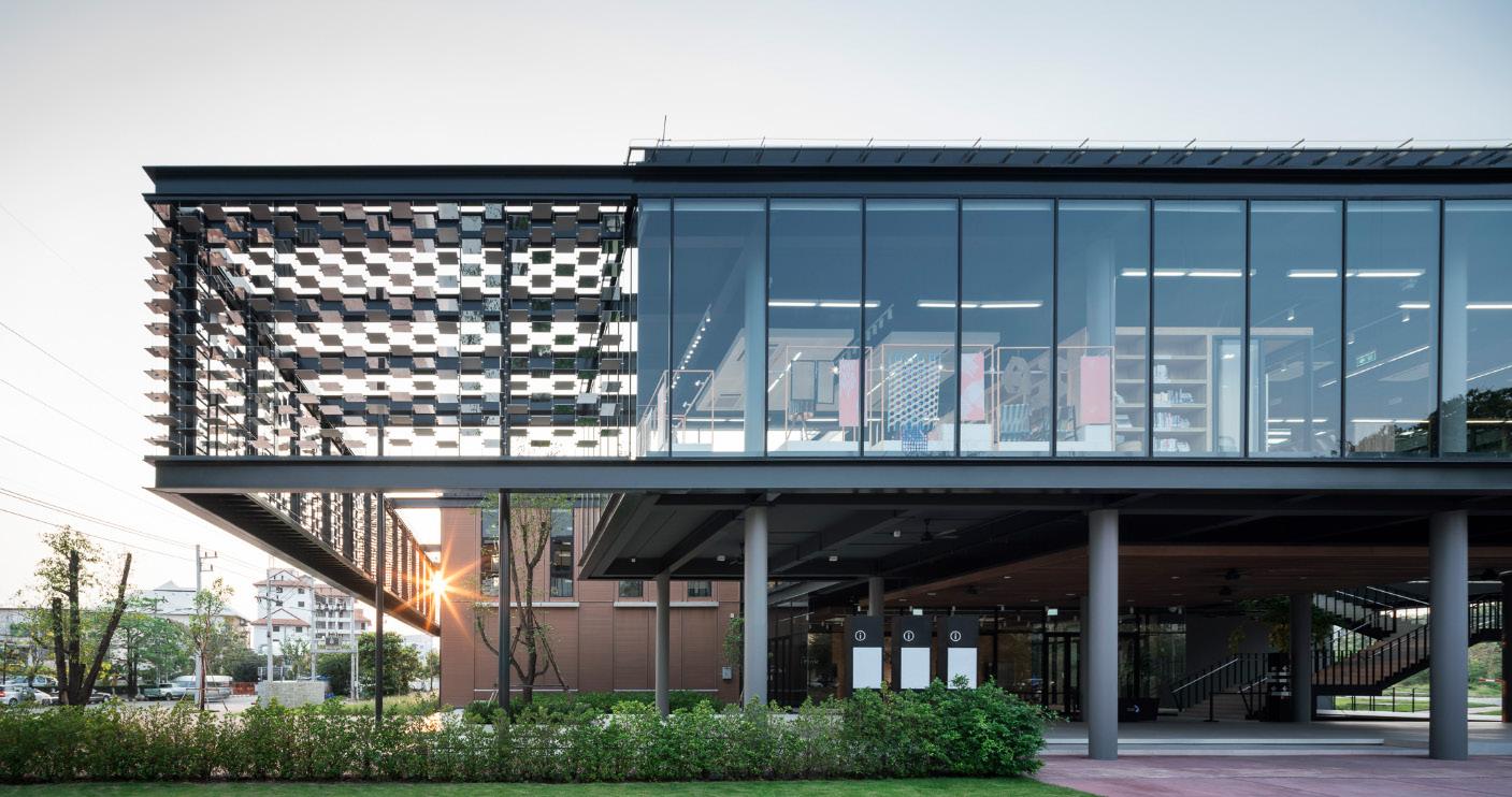
The TCDC building promotes many interactive space within the program. A unique feature the building has is its facade. Its role would be creating a street signage for people who are passing. Its rotating reflecting panels are able to act as a shading device when closing the panels. It also has mirrors to emulate the activities that are occurring inside. Lastly these panels are a creative interactive feature which engages the user in creating words of patterns.
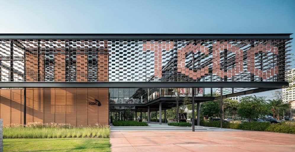
One of the interesting features the building possess is its facade. I love the fact that its facade becomes a element of branding, building system (shading) and an interactive attribute. I believe designing a facade that engages the general public creates character.
20
TCDC
KHON KAEN PROJECT: TCDC KHON KAEN PROJECT TYPE: Community Hub SIZE: 1,500 sqm LOCATION: Isan, Thailand COST: 1.9 Million Dollars ARCHITECTS: A49 AWARDS: NA DATE: 2020
HTTP://WWW.A49.COM/PROJECTS/VIEW/404 EXTERIOR OPERABLE PANELS
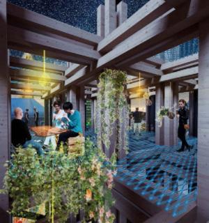
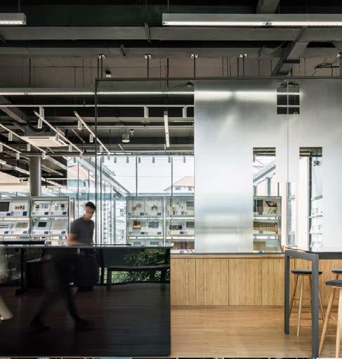
The buildings design purpose is to create spaces that provide a flourishing of activities and educational elements. In the picture to the left the softness of materials plays well in creating warm spaces in the room. The use of the curtain walls fabricates a transparent element from the inside and outside of the building. The tables that turn into shelves create a cohesive study area.
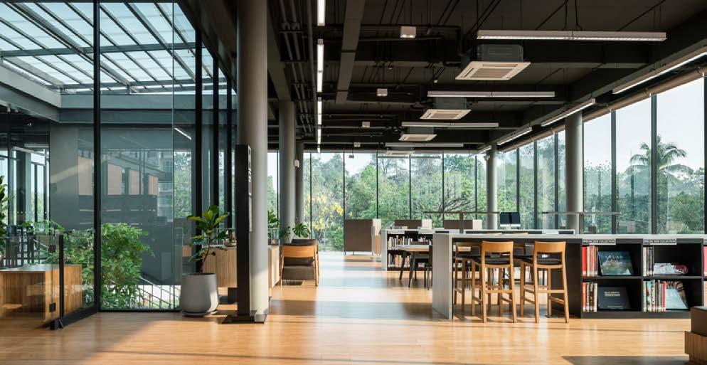
What’s gathered from the image to the left is how the space uses transparency and materiality to produce a space which people would enjoy to spend their time in. The ability to look outside is something I look forward in creating for my design as well as using proper materials to construct a beautiful interior.
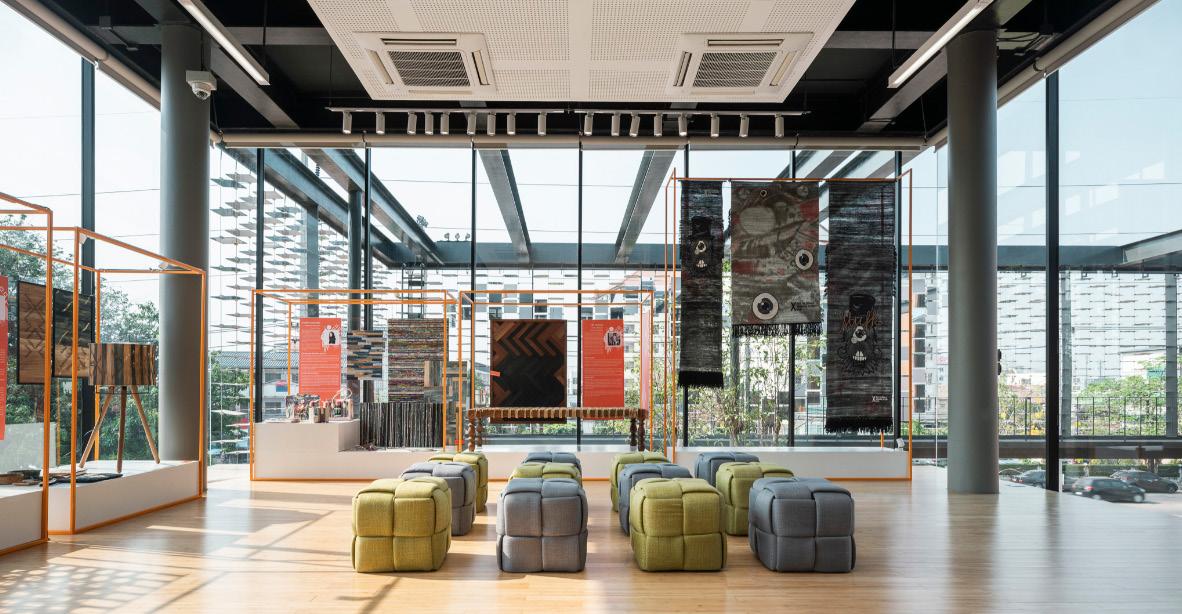
The image to the left shows how the double heighted space creates an airy ad light room for the user.
The fun chairs allude to a space of learning also for lecturing. The space represented plays into a gallery space with artifacts on stands and art work thats in display.
What’s gathered from the image to the left is the production of a multi use space. Spaces like this help manipulate a room to become different spaces for activities. Through my design assembling a space where different events could take place becomes a priority. Spaces like a game rooms, meeting rooms, party rooms, learning rooms, etc. These would also relate to a pandemic, providing rooms if needed.
21
HTTP://WWW.A49.COM/PROJECTS/VIEW/404 STUDY AREA
MULTIPURPOSE
SPACE
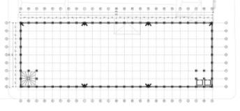
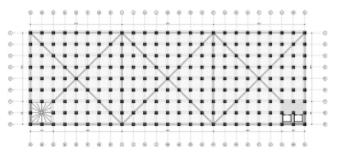
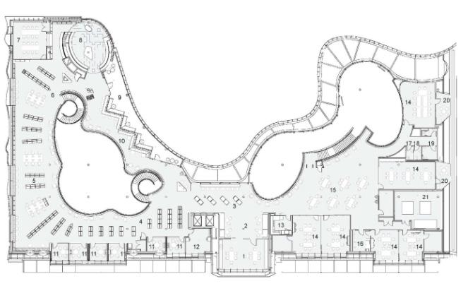
The first floor of the building hits strong on developing spaces where the user would interact and congregation with other people. The first floor becomes the public sector of the building. It has an exhibition space a court yard, a reception hall, a seminar space, a fish pond and other rooms that houses mechanical, toilets etc. The spilling of trees through the plan produces an image that the building is in a forest.
Looking at the plan it gave me an idea about what spaces should come first. What spaces should greet you when walking into the building. Also how big the space should be.
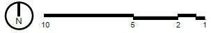
22 FIRST FLOOR
HTTPS://DE51GN.COM/ARCHITECTS49-DRAWS-ON-TRADITIONAL-ELEVATED-STRUCTURES-TO-CREATE-CONTEXTUAL-AND-CREATIVE-COMMUNITY-HUB-IN-NORTHEASTERN-THAILAND/
INTERIOR GROUND FLOOR
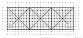
The second floor of the building becomes the space where people would general go to get work done or learn. This would generally be the library room. The space is met by learning sectors as well as private lounge areas. The openness allows to see into the court yards with trees flourishing the area.
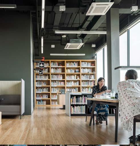
What I could terminate from the plan is how the library space creates moments where there are private and open lounge areas. Learning areas. Interactive opportunities from the balcony. Also areas for small meetings. These elements would help my design of a library space become interactive and educational.
23 SECOND FLOOR
HTTPS://DE51GN.COM/ARCHITECTS49-DRAWS-ON-TRADITIONAL-ELEVATED-STRUCTURES-TO-CREATE-CONTEXTUAL-AND-CREATIVE-COMMUNITY-HUB-IN-NORTHEASTERN-THAILAND/
SECOND FLOOR STUDY SPACE
PROJECT: Modular Framework
PROJECT TYPE: Community Hub
SIZE:
LOCATION: Adelinia, Australia
DESIGNER: NOMA
The structure becomes an embodiment of defining space. The buildings modular framework could be organized by users. This spilling of structure into the street invites people to collectively establish their own little store. The frameworks modularity invites groups of designers, artist, craftsman etc. The process diagrams helps with where, how and why the project is.
Ultimately structural expression is the theory that I want to prove for my building. Spill the structure and creating space outside for recreational and consumer usage is very powerful. The process diagrams would help show where, how and why I came up with some of the design decisions made.
24 MODULAR FRAME WORK
NA
COST: NA
AWARDS: NA DATE: 2017 PROCCESS DIAGRAMS
HTTPS://WWW.NOMASTUDIO.COM.AU/WORK/14-ARCHITECTURE/96-ADELAIDE-CREATIVE-COMMUNITY-HUB.HTML
The site plan allows for spilling this modular framing in and around the site. Sprawling from the building it touches the ground and creates this majestic jungle gym for people of all ages. Its consistent use of the square helps define open spaces and paths on the site. The growing of modular vegetation also relates to the framework, spilling and nestling the building. These terraced frames helps define public space. It accommodates for a variety of activities, performances and events.
The floor plans walks through the different events designed on each floor. Meshing the modular frame work and greenery into the building. Meshing all aspects of the site into the building. The plans illustrate how the spaces are organized by hierarchical importance.


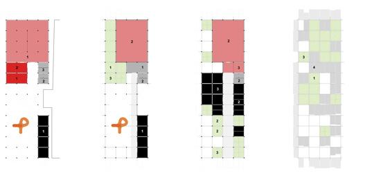
The diagrams presented on this page show how meshing the structure and site together help a relationship towards the form. When designing I would have to look at spaces within my building that could bleed into the outside spaces. Drawing the building to interact outside and inside. Demonstrating structural expression. The building program would also have to some how have rooms where the structure could relate with the structural interaction, and receive it on the outside of the building. Interlocking both site development and building program would help with developing a free flowing community hub.
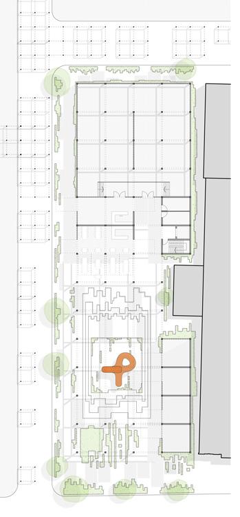
25 GROUND FLOOR PLAN SCALE 1 : 250 ORGANIZATIONAL DIAGRAMS
HTTPS://WWW.NOMASTUDIO.COM.AU/WORK/14-ARCHITECTURE/96-ADELAIDE-CREATIVE-COMMUNITY-HUB.HTML
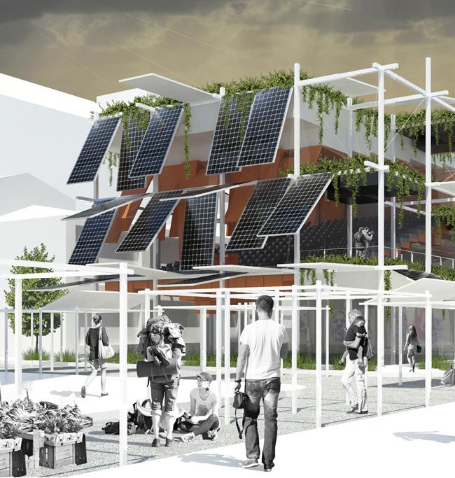
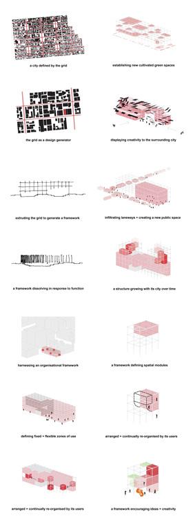
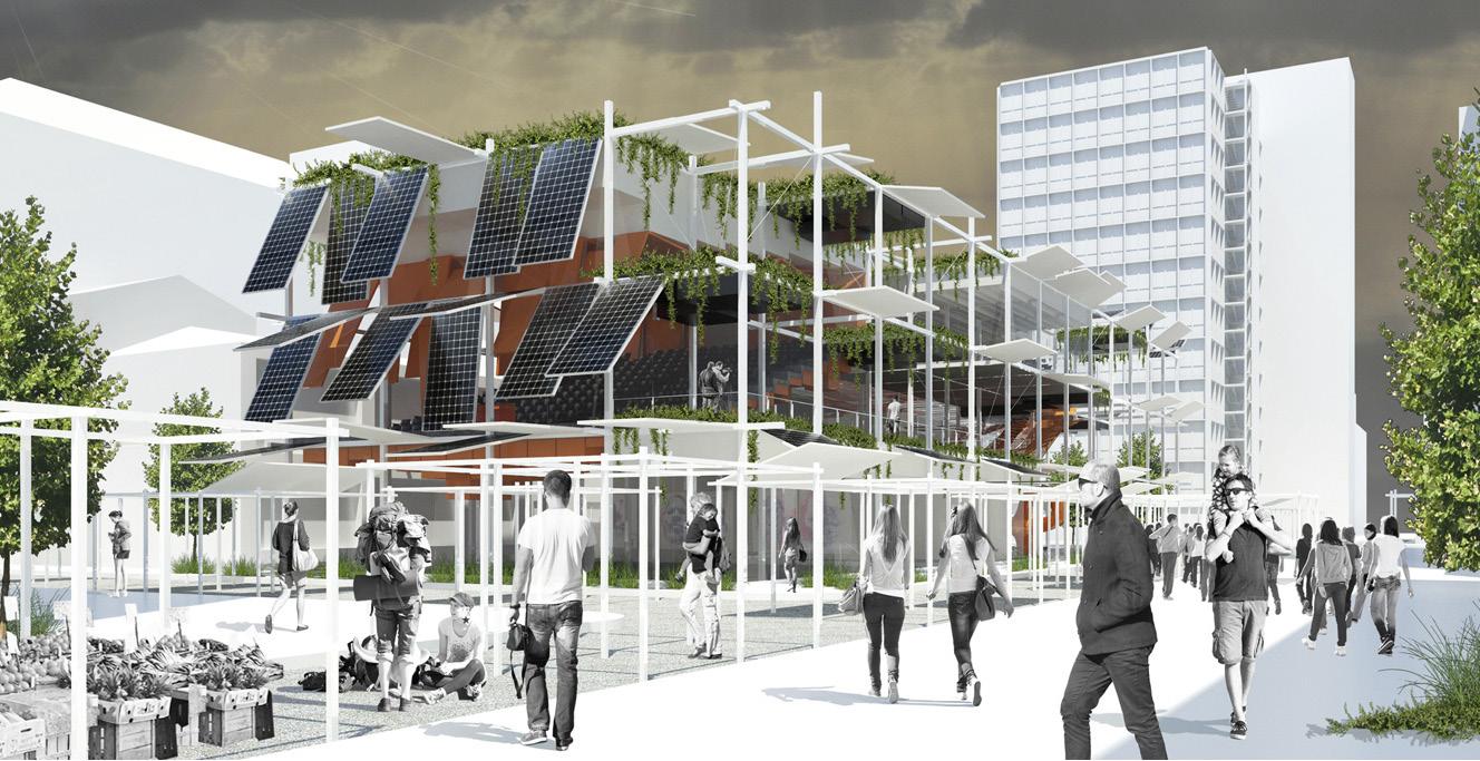
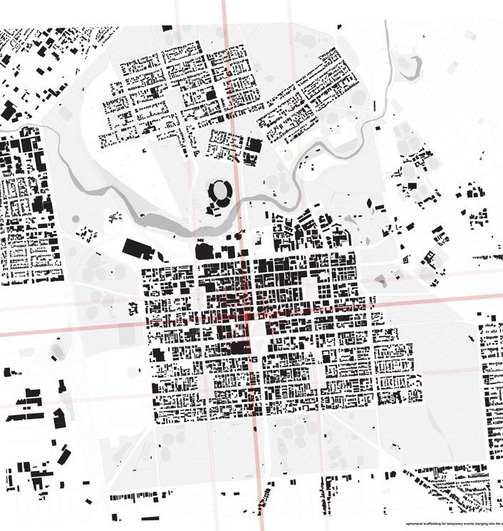
The site is seen to be on this grid lock like plan. This gridded plan would conceptually present itself a the buildings form because of it structured modularity. The building accommodates for an imagination of creativity, developing the city over time. The designer of the project wanted to utilize a two “dimensional grid” and erect it since its part of the location historic development. Within the site the building has the ability to be flexible, adaptable and expand. The frame work would be utilized for a permanent or temporary uses. The purpose for many of the design decisions made on the building is to encourage interaction. When taking a step back and looking at the project it seems like the scaffolding of the building is expanding outward to the streets of Adielinia. The exterior image help facilitate the functions the building represents. For sustainability purposes the building proposes to apply operable solar panels on the building and through the site. The meshing of vegetation shows how both ground and roof of the site and building meet.
All in all, the site plan helps see the bigger picture. Where the site is in relation with the open areas, i should do the same. I would accommodated needed spaces within the building which the site lacks. The exterior image help me think about sustainable systems. Applying these systems from the beginning of the project would characterize form. The spilling of building components to the site is also key. These end points would help prove my proposal true.
26 HTTPS://WWW.NOMASTUDIO.COM.AU/WORK/14-ARCHITECTURE/96-ADELAIDE-CREATIVE-COMMUNITY-HUB.HTML SITE PLAN
27HTTPS://WWW.NOMASTUDIO.COM.AU/WORK/14-ARCHITECTURE/96-ADELAIDE-CREATIVE-COMMUNITY-HUB.HTML EXTERIOR IMAGE
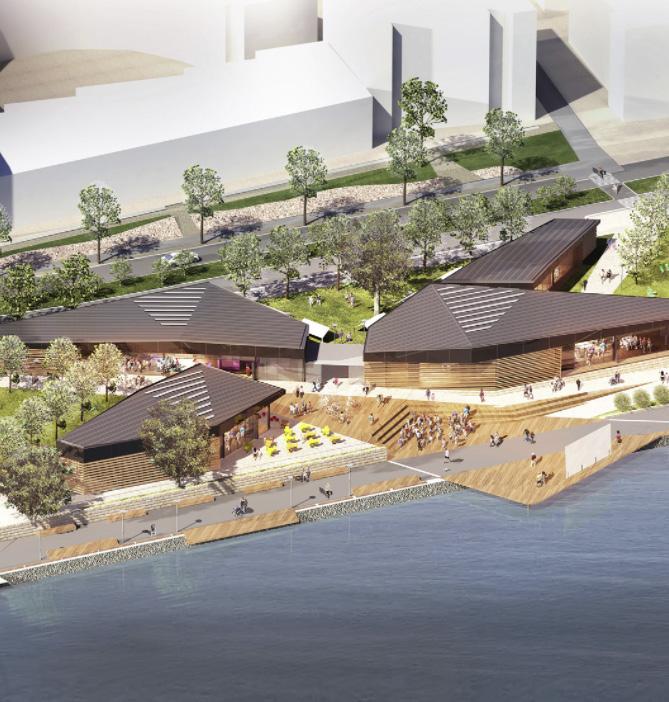
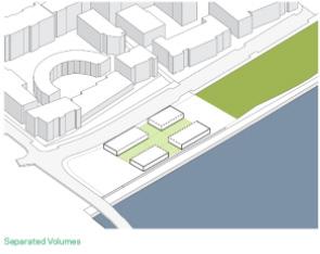
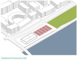
The firm wanted to redesign the uses of the community hall and the civic spaces. The buildings design takes one mass structure splitting it into four separate buildings creating different outdoor pavilions. Many of spaces within the buildings were designed to create views towards the water front. Creates views, privacy, flexibility and activity events. The Exterior share the same materials, but interior the buildings have different spaces and functions. The waterfront creates a special opportunity for usage.
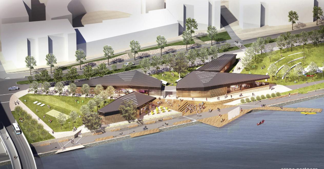
In conclusion creating spaces for public use from the building form becomes very important since my site is touching the water. Also designing outdoor pavilions would shape the site.
PROJECT:
PROJECT
28 THE CONNECTION TO RHODES
The Connection Rhodes
TYPE: Community Hub SIZE: 1,800 sqm LOCATION: Rhodes, NSW, Australia COST: NA ARCHITECT: Crone Architects AWARDS: 2018 nsw Architecture Design DATE: 2013 - 2017 EXTERIOR PIER
HTTPS://CRONE.COM.AU/PROJECT/RHODES-COMMUNITY-CENTRE/
PROCESS DIAGRAMS
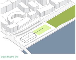
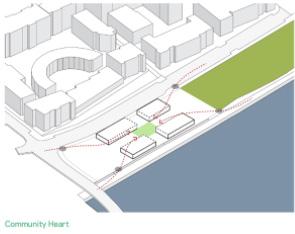
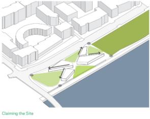
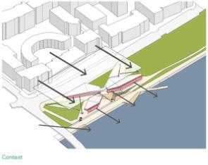
The process diagrams outline building form. The surfaces split into four different spaces. The highlighted site represents the opportunity to give back to the community. Dividing spiting and spreading these four spaces to create special outdoor spaces. Once the massing are split arrows indicate how you may circulate through the program. The massing start to take shape, turning paths into special paths ways. The buildings mass and shape starts to help create access paths towards the waterfront.
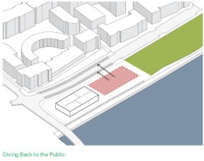
To sum up, considering the process of diagrams, they help illustrate purpose towards building form. I would adopt this conceptual process. This shows how I got to my building shape and size. The why.
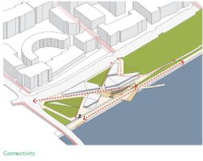
Once it all comes together the design ideas start to narrate what the project is trying to convey from the axon. These integrated masses create beautiful opportunities for pocket spaces outside. There are green spaces east west and north of the buildings. The diagram on the left shows the walk way near the water front. Attached to the walkway an amphitheater over looking the water. One feature is connection the highway and water front to allow access to the site.
In a nutshell this axon is a great precedent for my design. An axon could help convey the sites success with connecting to the building. Its also an opportunity to show site context and create sustainability diagrams.
29
SITE
PLAN
AXON
HTTPS://WWW.ARCHDAILY.COM/470878/CRONE-PARTNERS-RETHINK-THE-COMMUNITY-CENTRE-IN-RHODES
The projects goal is to design spaces that create a different typology throughout the site. Their idea was not to stop at on massive monolithic building form. It was to split the massive program and successfully place them in relating distances. Through the process of designing they came up with splitting the building into four sectors, “four pavilions”. These building and site would house a variety of programs. Like, a cafe/ restaurant, digital gallery, e - resource rooms, learning suites, multipurpose hall, community meeting rooms/ playgroups, water play space, amphitheater over water platform and integrated public art areas. By splitting the building the firm was successful in responding to the site and creating pockets of activities around the buildings. The arrangement of the buildings create a dialogue with the site, it develops a variety of beautiful events spaces in and around the site. It help incorporate the water by designing a platform that extrudes into the sea. This becomes a net work of “playful, sustainable, and optimistic” experiences.
All in all, this project is the best precedent for my design. It address how the program could shrink and create outdoor events. It addresses the water feature and the highway element. This projects could help cohesively blend a lot of the site and building designs for my project to develop a successful thesis.
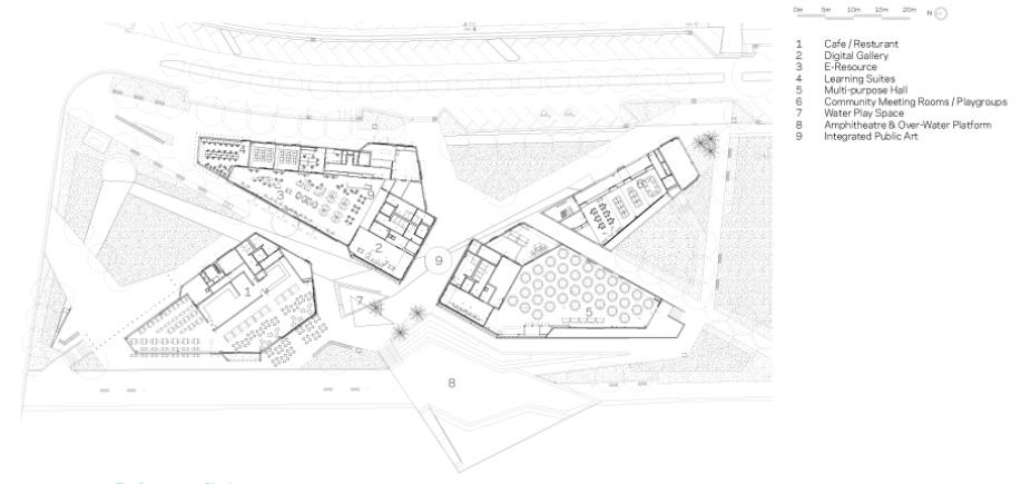
30 FLOOR PLAN
HTTPS://CRONE.COM.AU/PROJECT/RHODES-COMMUNITY-CENTRE/
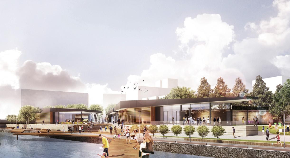
The images represent a wide variety of moments where the building does a great job addressing its design for the community. The exterior pedestrian trail image shows how the building and site relate with one another. The difference in elevation could be because water flooding. The image with trail along the edge shows a great relationship between building and the amphitheater platform. The e-resource space illustrates great qualities of materials and furniture.
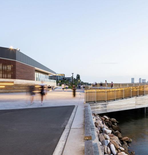
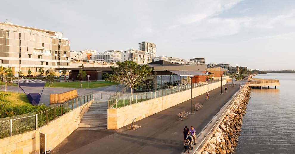
In a word, wonderful images. For my project I will strive to render images that create a narrative about the building and site. Rendering an interior image showing materiality and human interaction within the space. Bring life to a project.
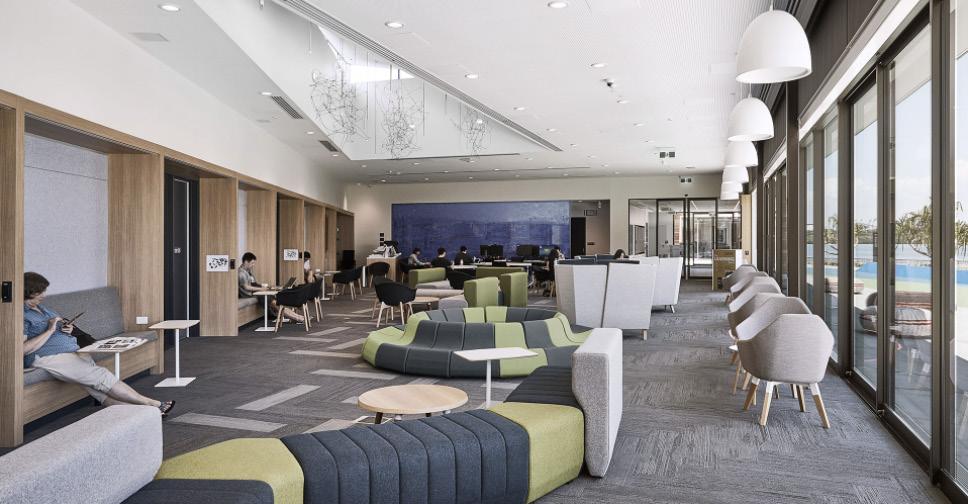
31 E-RESOURCE SPACE EXTERIOR PEDESTRIAN TRAIL TRAIL ALONG THE EDGE
HTTPS://WWW.ARCHDAILY.COM/470878/CRONE-PARTNERS-RETHINK-THE-COMMUNITY-CENTRE-IN-RHODES
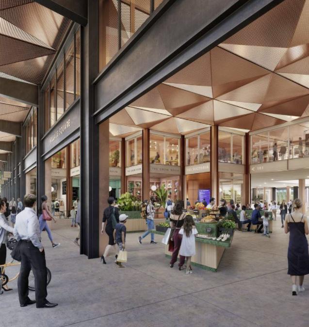
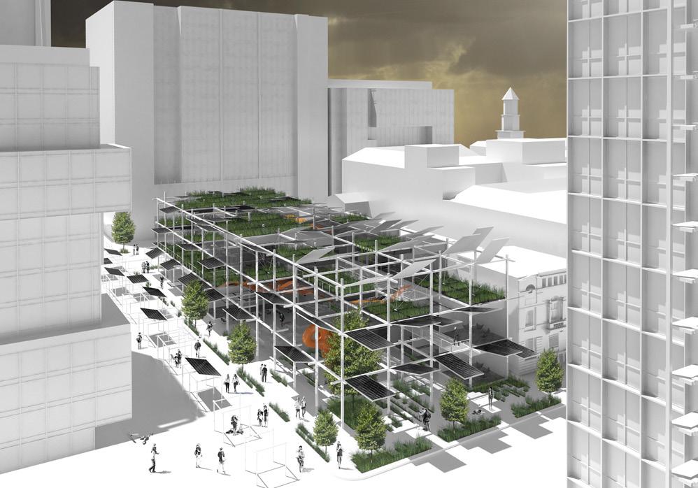
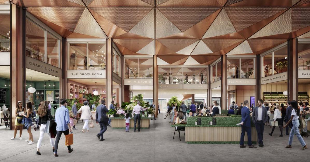
This mixed use project incorporates an urban plaza, office spaces and an abundance of indoor and outdoor amenities. This integrates interaction elements to join people into a space. The large covered plaza meanders through the building allowing it to adapt to a variety of city events. The images demonstrate how this congregation of human interaction occurs in the space.
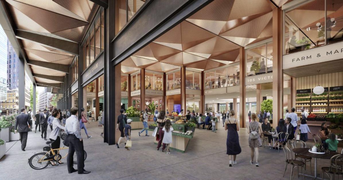
For my design I would take these images as inspiration. The elaborate ceiling does a great job creating a beautiful pattern. Exposing the columns to celebrate the structure is also design feature I want to celebrate. The food stands shown in the image is a great function for pooling people inside the space.
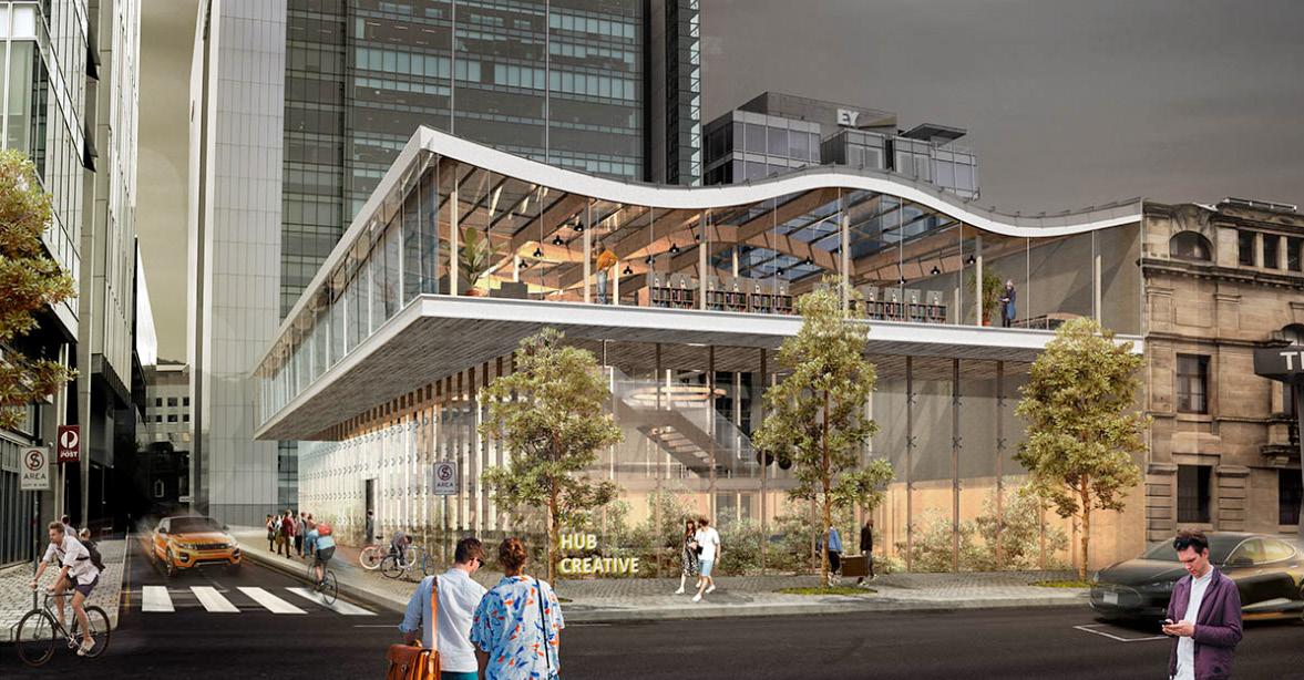
32 PROJECT: Active Hub PROJECT TYPE: Community Hub SIZE: NA LOCATION: London, Westminter COST: NA DESIGNER: Adamison Associates Architects/ KPF AWARDS: NA DATE: Start 2022 ACTIVE HUB HTTPS://WWW.BDCNETWORK.COM/HENNING-LARSEN-DESIGNS-ACTIVE-COMMUNITY-HUB-LONDON
EXTERIOR GROUND
LEVEL
INTERIOR LECTURE ROOM
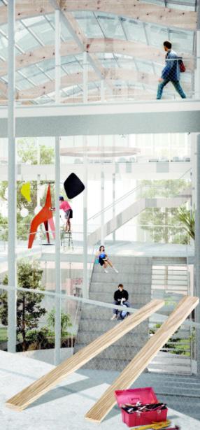
The interior recreational space represents hierarchy of levels within the building. All floors are met with a spiral stair case which predominately becomes the grand stair case. A tree placed in the middle metaphorically helps the stair case wrap around the space. Throughout the building there are allowable areas for recreational uses. The image represents is a great example of material and function of spaces.
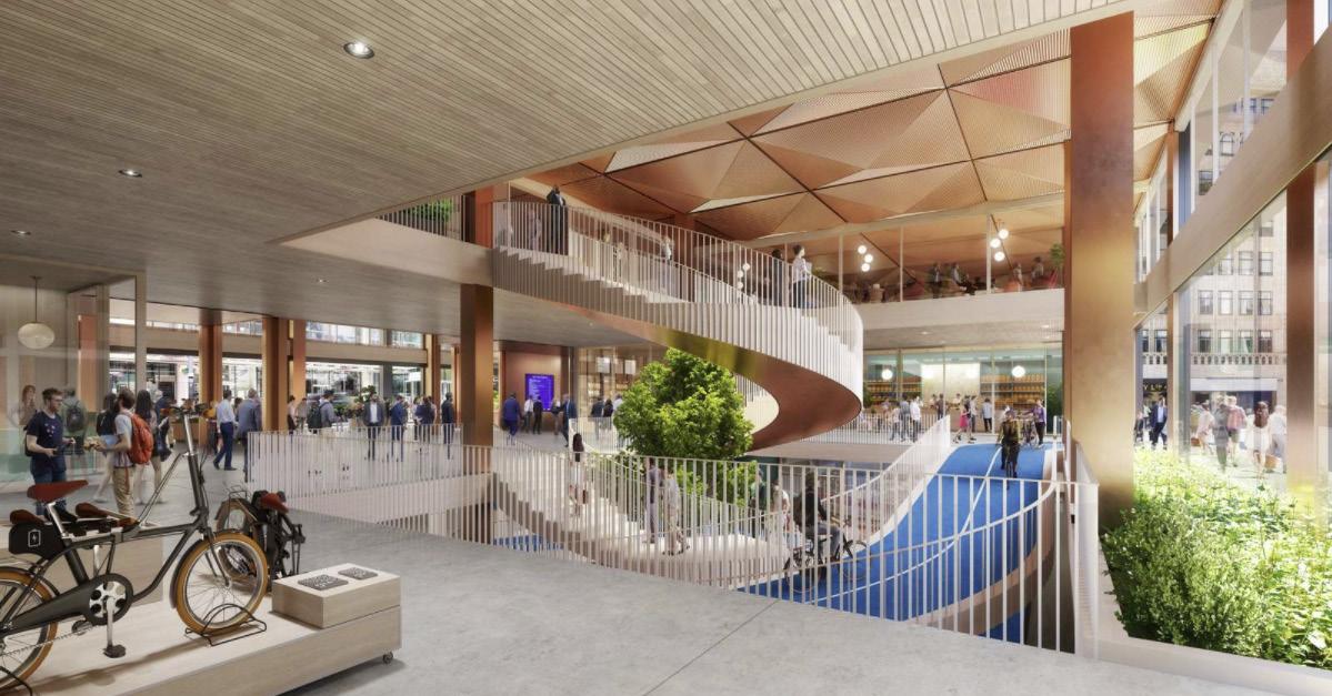
To sum it up this interior rendering would become a great precedent for my project. Creating an interior rendering in my project showing a space where different activities are presented would help narrate my ideas.
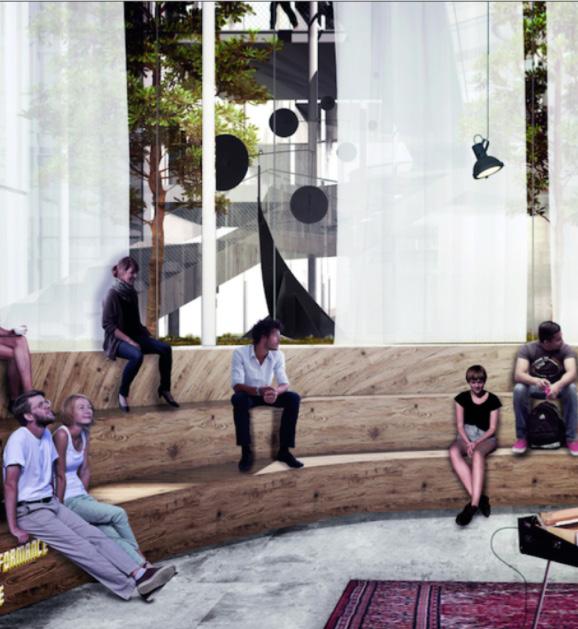
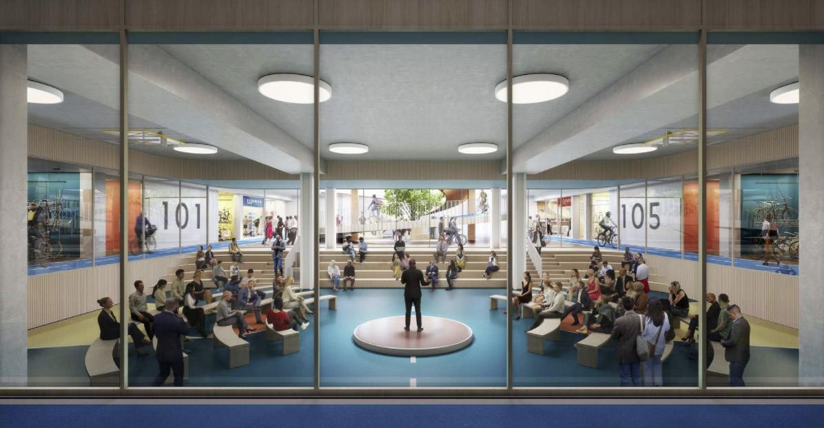
Throughout this project. The end goal is to generate spaces or facilities where events like art exhibits, music events, offices, markets, retail stores,sports and fashion runways. This project was able to satisfy the BREEAM standards, to reach a net zero building. The interior lecture room is one of the many spaces where people are with one another sharing a special moment.
To finalize my deduction my end goal is to create many spaces within my project where congregation of multiple users are able to be. Having many eventful areas mixed in with recreational spaces combined with access to meals and refreshments.
33HTTPS://WWW.BDCNETWORK.COM/HENNING-LARSEN-DESIGNS-ACTIVE-COMMUNITY-HUB-LONDON
INTERIOR RECREATION SPACE
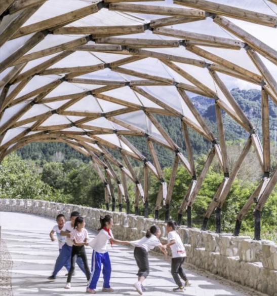
PERGOLA
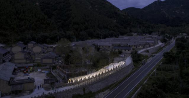
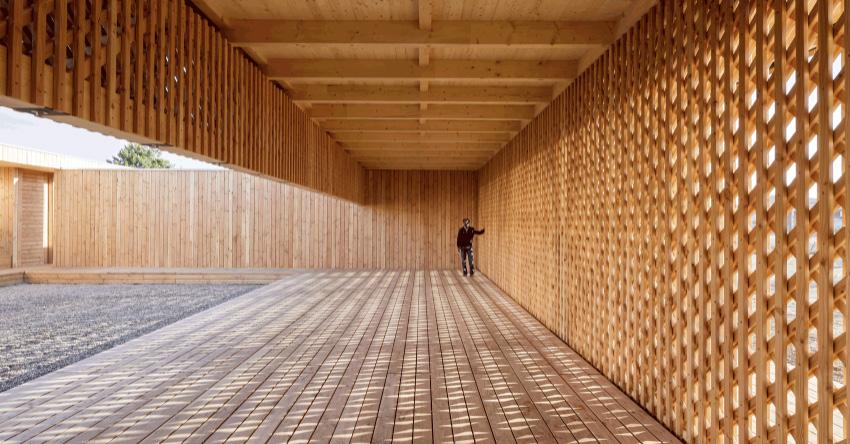
The pergola creates a journey through this walk way. This project re uses materials which were thrown away. This elaborate structurally expressed walkway becomes a space for interaction and play.
From the images shown, this project would help influence some of the design decisions I make. The structurally expressed walk way becomes this node. This land mark element. Moving forward when designing my site my idea would be to fabricate some of these design features throughout my building and the site.
34
LUOTUOWAN PROJECT: Pergola Luotuowan Village PROJECT TYPE: Community Hub SIZE: NA LOCATION: Luotuowan, China COST: Recycled Material DESIGNER: Luo Studio REWARDS: NA DATE: 2019 HTTPS://WWW.POSITIVE.NEWS/ENVIRONMENT/SUSTAINABLE-DEVELOPMENT/THE-COMMUNITY-HUB-MADE-FROM-SALVAGED-WOOD/
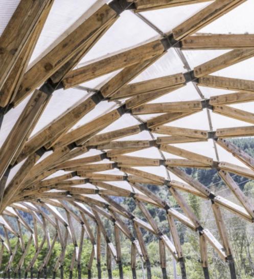
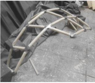
STRUCTURAL CONNECTIONS
PERGOLA + PEOPLE
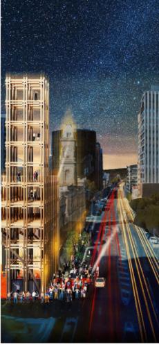
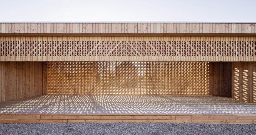
The pergola also becomes an element of branding. Especially at night this structure lights up at night. This helps indicate location, where you are either if your walk along the site of driving. The beauty of the image is how old and new come together. That stone wall came first, it became a barrier for protection. Later came this pergola which helps soften the harsh stone material.
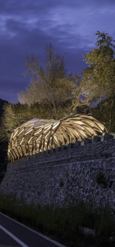
The next three images is a cultivation of models and mock ups in order to get a sense of how to building the pergola. The different techniques shown help illustrate what could be placed on the site and how could this element be designed. The use of different materials to connect certain elements becomes important.
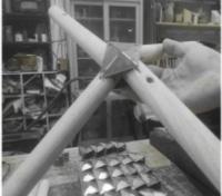
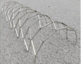
Analyzing all four images there are a series of design techniques that I should adopt. For example material, contrasting what elements are important and different. I want to be able to show what features of the building and site become interesting. The vast amount of model iterations would help me visualize how the building could fit on the site. At what direction the building would face. What would be the connector pieces to create a cohesive circulation over the highway. Model making would become a huge driving force to illustrate my thought process and reasoning for the design decisions made. Lastly the “money shot” creating a night rendering of the project to celebrate its beauty and complexity.
35HTTPS://WWW.POSITIVE.NEWS/ENVIRONMENT/SUSTAINABLE-DEVELOPMENT/THE-COMMUNITY-HUB-MADE-FROM-SALVAGED-WOOD/
PERGOLA NIGHT IMAGE PROCESS MODELS
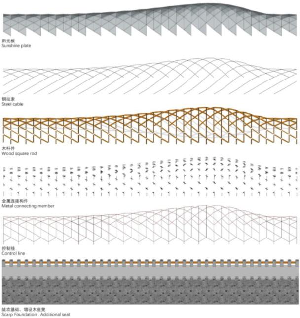
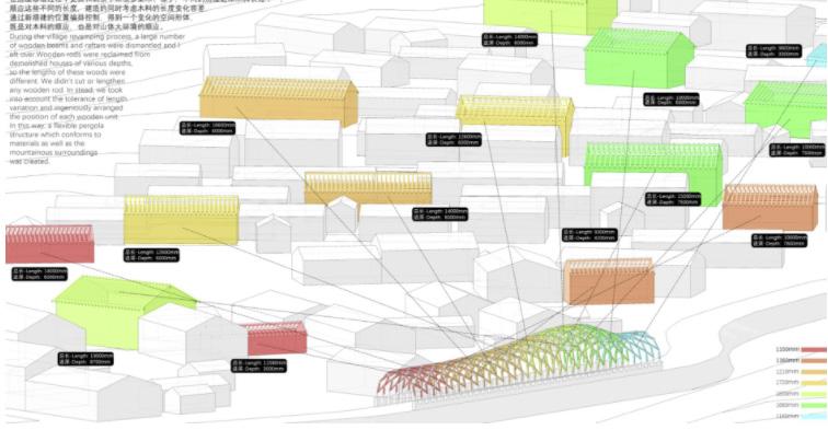
STRUCTURE DIAGRAMS
The structure diagram illustrates the process of how these members within the site are connected. It represents how many different design components were introduced into the structure of this Hub. From starting with the existing bridge. To the control line material, which helps frame the pergola. To the use of metal connecting members. To applying the recycled wooden square rods. To the steel cable, which helps suspend the pergola. To finally placing a sunshine plate, which creates a shading sheathing on top of the pergola. This elevation of structural diagramming helps analyze how the pergola was constructed. Also how many different types of elements were put together. Visualizing this plan would help create beautiful diagrams throughout my presentation and final design. Illustrating the construction process would help dialogue how my building was put together. By trying to adopt these diagrams I could show what materials where implemented into the design and how they were applied to the building.
36 HTTPS://WWW.POSITIVE.NEWS/ENVIRONMENT/SUSTAINABLE-DEVELOPMENT/THE-COMMUNITY-HUB-MADE-FROM-SALVAGED-WOOD/
PLAN SITE PROGRAM RELATION
The site plan helps with locating and representing where the pergola is placed. With its boldness you can see why the pergola was place in the trail. Analyzing the plan helps conclude how people in the town would get around the site.
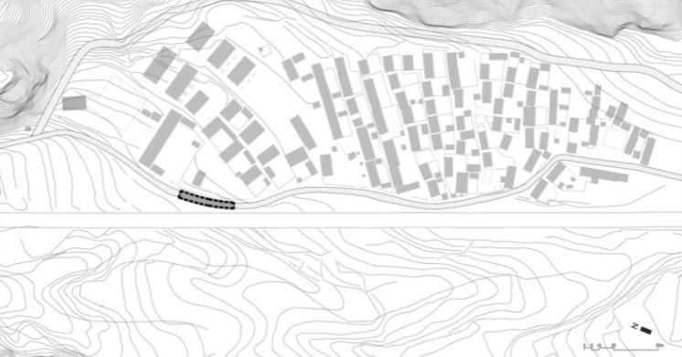
With the information shown I could represent my site in a bolder scale. Zooming out would help someone see where they can approach the site. They could also assume as to why I made some of the design decisions.
This site program relation helps depict what types of building are around the pergola. Its indication shows the difference of residential living and commercial uses. This site inventory helps the project give site relationship towards other feature of the site.
In conclusion creating a site inventory plan would be very helpful in locating what is around the site. Also indicating how far the building would be in relationship to the residence of the area. This study would help give reasons why I chose certain programs to be within my building.
37HTTPS://WWW.POSITIVE.NEWS/ENVIRONMENT/SUSTAINABLE-DEVELOPMENT/THE-COMMUNITY-HUB-MADE-FROM-SALVAGED-WOOD/ SITE
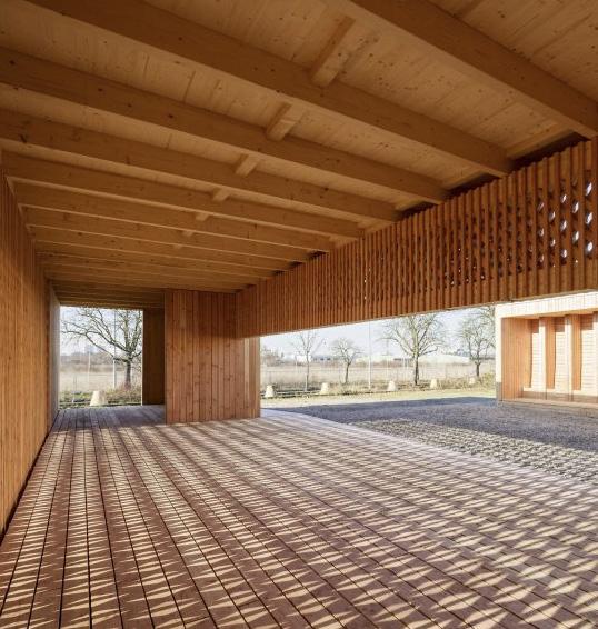
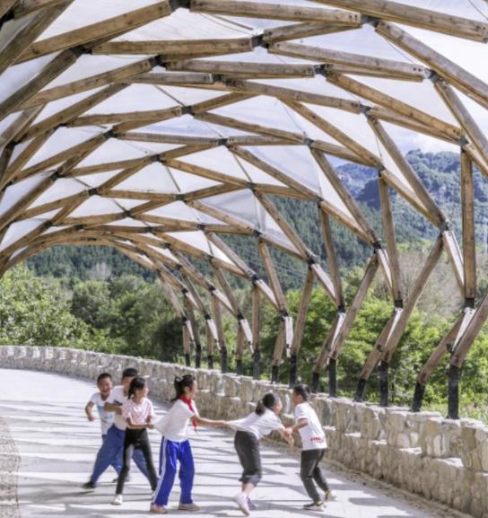
38 LATTICE WOOD PROJECT: Lattice Wood PROJECT TYPE: Refuge Camp SIZE: NA LOCATION: Manheim, Germany COST: NA DESIGNER: Students/ University of Kaiserslautern AWARDS: NA DATE: 2017 HTTPS://WWW.DEZEEN.COM/2017/02/22/SPINELLI-COMMUNITY-CENTRE-GERMAN-REFUGEE-CAMP-MANNHEIM-UNIVERSITY-OF-KAISERSLAUTERN/#/ MAIN PAVILION IMAGE 2 MAIN PAVILION IMAGE 1
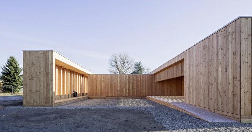
Eighteen Architecture students from Germany’s built this wooden structure. It is a building which becomes a communal center for refugees. This camp is located in Mannheim, Germany. This pavilion was designed to create shelter and protection for refugees. The unique design of the pavilion fabricates areas of congregation and relaxation. The images demonstrate an environment where building and site become uniform with on another. Soft uses of this bleached wood color mutes itself. Both site and building relate with one another. It becomes a place where refugees are able to learn new skills, and give the volunteering jobs with some of the basic building skills. This beautifully designed pavilion follows a very symmetric and organized elemental features.
In conclusion these materials used throughout the building become wonderfully organized by repetition and symmetry. When designing my project I would take into account on how to create beautiful spaces throughout the site. Develop areas where the building would interact with the site. Making the building become part of the recreational space or sitting areas. Creating predominate entrances in order to pool people into the program. Another amazing feature is the ability to give back to the general public designing spaces where people are helped. Helped in educational uses, work uses, recreational uses etc. This would give the building a sense of placement and purpose.
39
HTTPS://WWW.DEZEEN.COM/2017/02/22/SPINELLI-COMMUNITY-CENTRE-GERMAN-REFUGEE-CAMP-MANNHEIM-UNIVERSITY-OF-KAISERSLAUTERN/#/ EXTERIOR ENTRANCE IMAGE 1 EXTERIOR ENTRANCE IMAGE 2 EXTERIOR ENTRANCE IMAGE 3
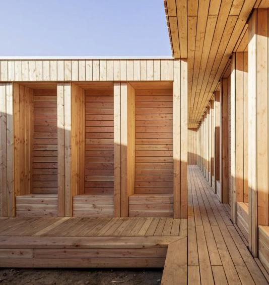
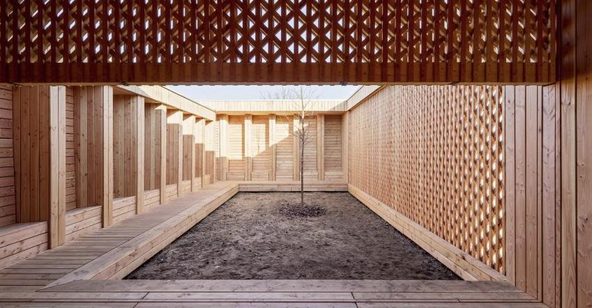
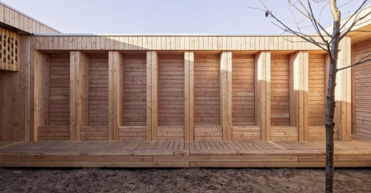
Illustrated from the pictures on the page, this space represents one of the many court yards within the pavilion. Its notion to still continue this organized repetition through its wooden pillars helps create seating benches inside the court yard. This court yard encases the tree shown in the images, metaphorically representing life growing from within. Indicating supporting life, just like being able to help refugees.
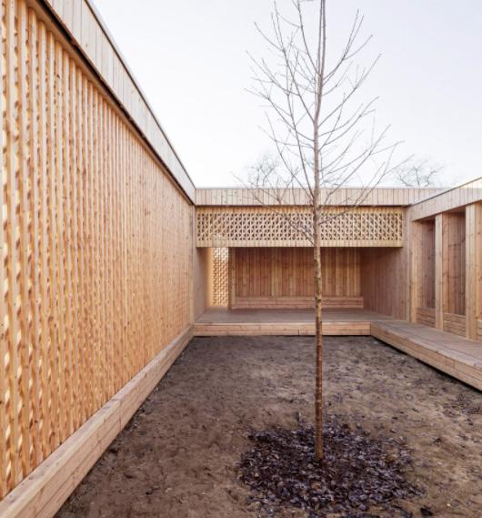
For my design I could create moments inside and outside the building where the structure would encase a green space to buffer out the outside commotion to implement a soothing space. The pillared benches could be a precedent by adapt my building to have seating along the sides or on a side.
40
HTTPS://WWW.DEZEEN.COM/2017/02/22/SPINELLI-COMMUNITY-CENTRE-GERMAN-REFUGEE-CAMP-MANNHEIM-UNIVERSITY-OF-KAISERSLAUTERN/#/ COURT YARD IMAGE 1 COURT YARD IMAGE 2
COURT
YARD IMAGE 3
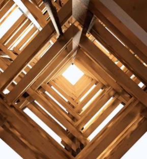
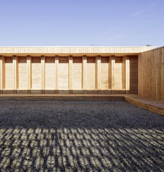
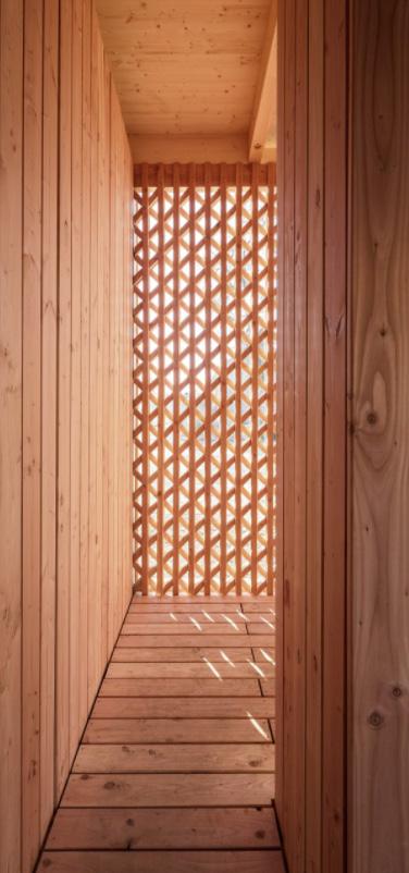
The pavilion is created by cross- laminated timber. A lot of the main walls on the building are a clad Douglas fir. These feature would help structurally support the building. One amazing feature from the images above is the perforated walls. This screen creates playfulness and warmth within the hall way. The perforation of the interior wall bleeds light into the space. Light bleeding into the hallway creates an illusion of being somewhere else.
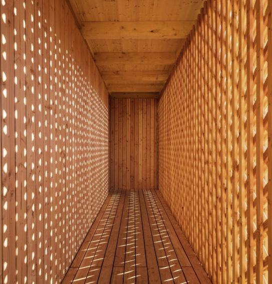
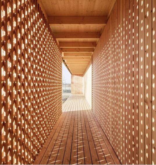
The images above show a great representation of light pouring into a space. Through my design, one of my efforts is the create an elaborate facade which allows a beautiful amount of light flowing into the building. Having a pattern on the facade would also create such unique characteristic.
41
HTTPS://WWW.DEZEEN.COM/2017/02/22/SPINELLI-COMMUNITY-CENTRE-GERMAN-REFUGEE-CAMP-MANNHEIM-UNIVERSITY-OF-KAISERSLAUTERN/#/ HALLWAY IMAGE 1 HALLWAY IMAGE 2 HALLWAY IMAGE 3
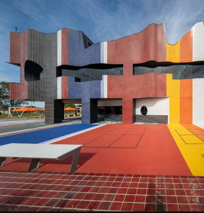
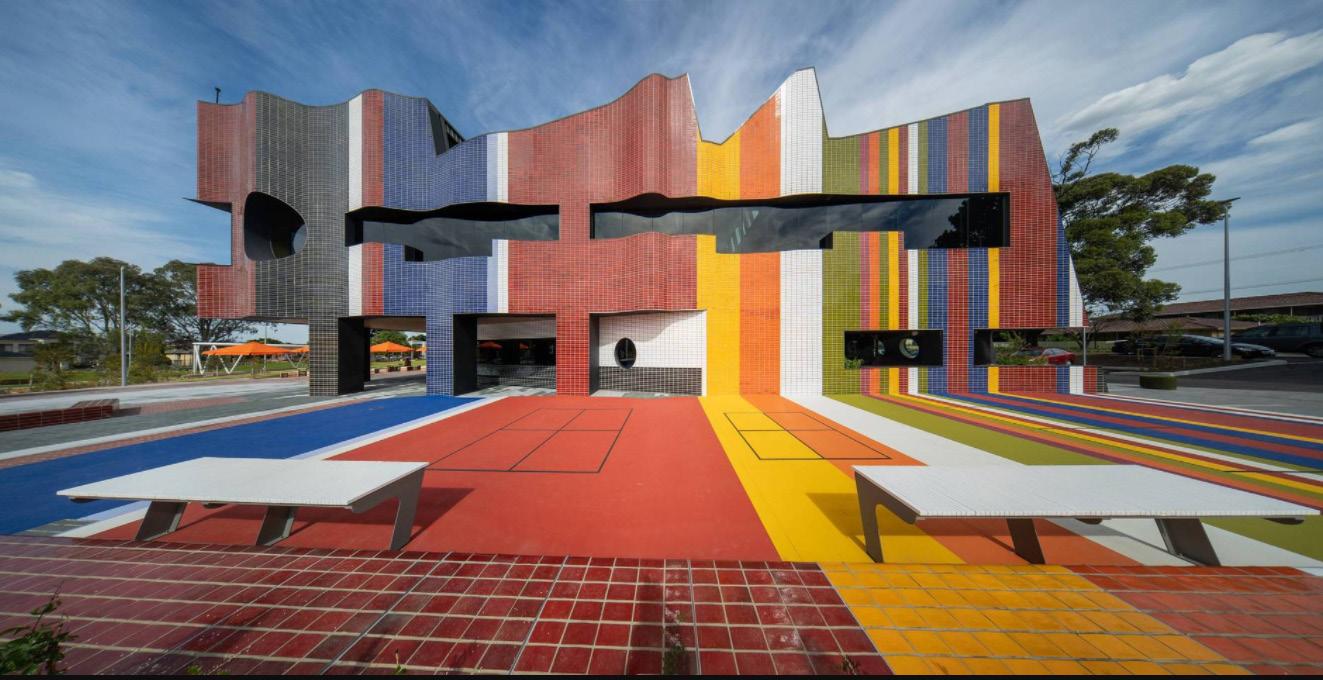
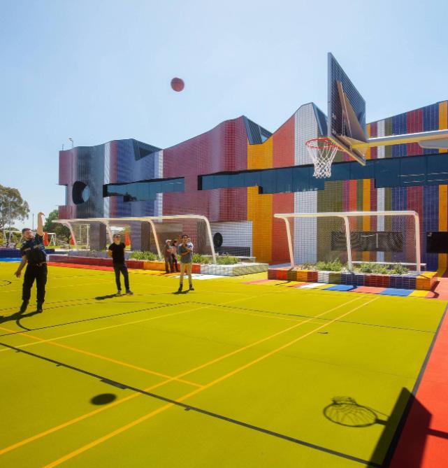
Springvale Community Hub is a project that incorporates civic spaces, a library and offices. Its site was designed for public recreation a parkland. The colors of the building are a pure representation of the cultural diversity from the Springvale community. Its diverse inter meshing of materials, color and spaces allow for diverse groups to experience in different manners.
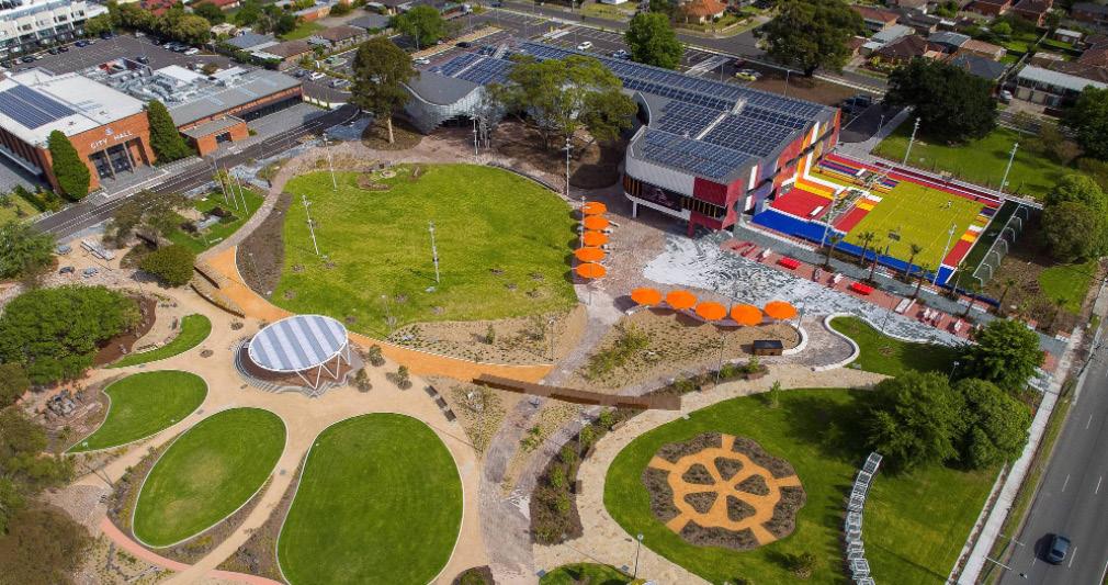
This is my anti precedent. I would not only disagree with the colors used throughout this project but also the from of the building. I personally think the building stands out too much and has a lot going on. This would be an example of not I do not want to convey in my project.
42 SPRINGVALE COMMUNITY HUB (ANTI PRECEDENT) PROJECT: Springvale Community Hub PROJECT TYPE: Community Hub SIZE: 3800 msq LOCATION: Springvale, Australia COST: NA DESIGNER: Lyons AWARDS: NA DATE: START 2020 EXTERIOR AERIAL VIEW
HTTPS://WWW.ARCHDAILY.COM/958384/SPRINGVALE-COMMUNITY-HUB-LYONS
The building was successful in a “6-star Green Star” carbon-neutral. Some of the sustainable systems are rainwater management, photo-voltaic panels, heating/cooling systems. The large windows allow the envelope to improve day lighting and reduce energy consumption. The floor plan show the complex program within the building representing many different spaces. The outdoor space show how the buildings colors bleeds on the recreational spaces unifying both attributes.
Another point to be made is how complex the floor plans are. I would disagree with creating a harsh organic space in the building. I do agree with the outdoor space and finding a balance of building and play.


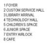
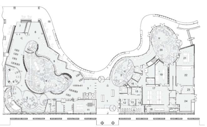

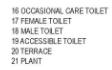
43 FIRST FLOOR SECOND FLOOR OUTDOOR RECREATION SPACE HTTPS://WWW.ARCHDAILY.COM/958384/SPRINGVALE-COMMUNITY-HUB-LYONS
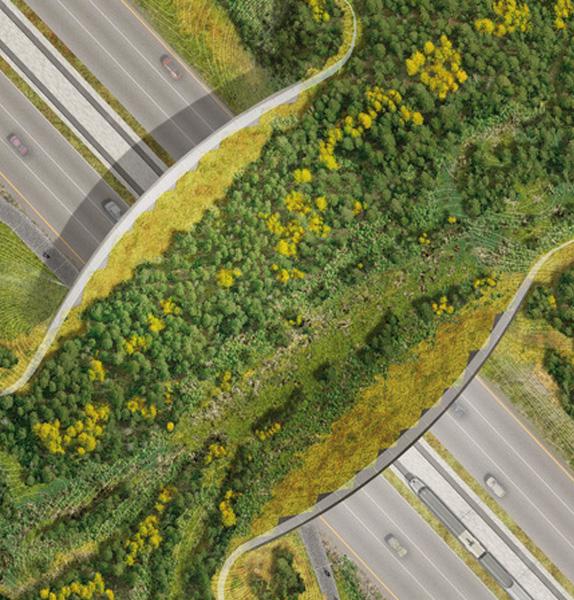
This land bridge is a beautiful landscape element that morphs over the highway. This allows animals to cross over safe and calmly. Another beautiful portion of the nature bridge is its mosaic like pattern on the under belly of the structure. Its curvature represents structural expression from its modular mosaic connections. Its organic form helps alleviate a lot of what a bridge usually looks like.
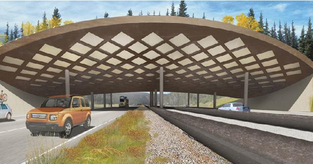
In a word, this bridge plays an important role for my design. Its organic form would help create a bridge that looks like its part of the land. Being able to combine land elements and structural components. Combining both would create the illusion that your not walking over the highway.
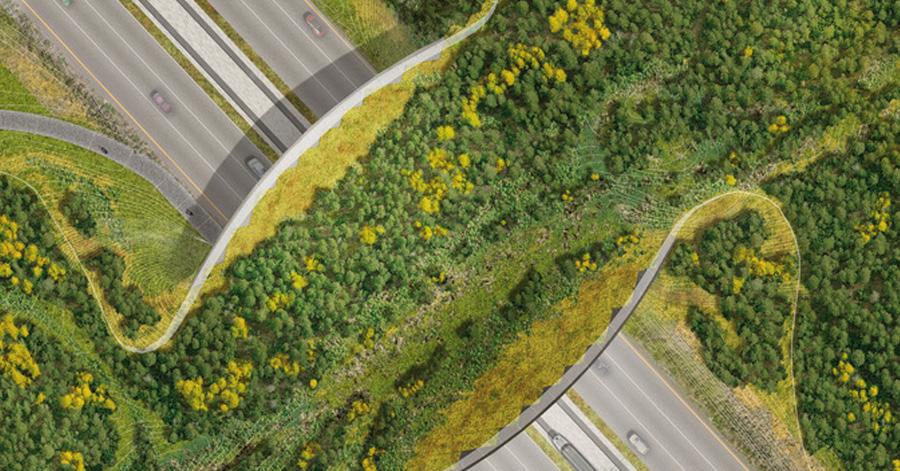
44 ARCH WILD LIFE CROSSING PROJECT: Arc Wildlife Crossing Infrastructure PROJECT TYPE: Land Bridge Competition SIZE: NA LOCATION: Vail, Colorado COST: NA DESIGNER: OLIN Studio AWARDS: Competition Winner DATE: 2010 HTTPS://WWW.THEOLINSTUDIO.COM/ARC-WILDLIFE-CROSSING-COMPETITION
HIGHWAY VIEW OF LAND BRIDGE
BRIDGE AXON STRUCTURE
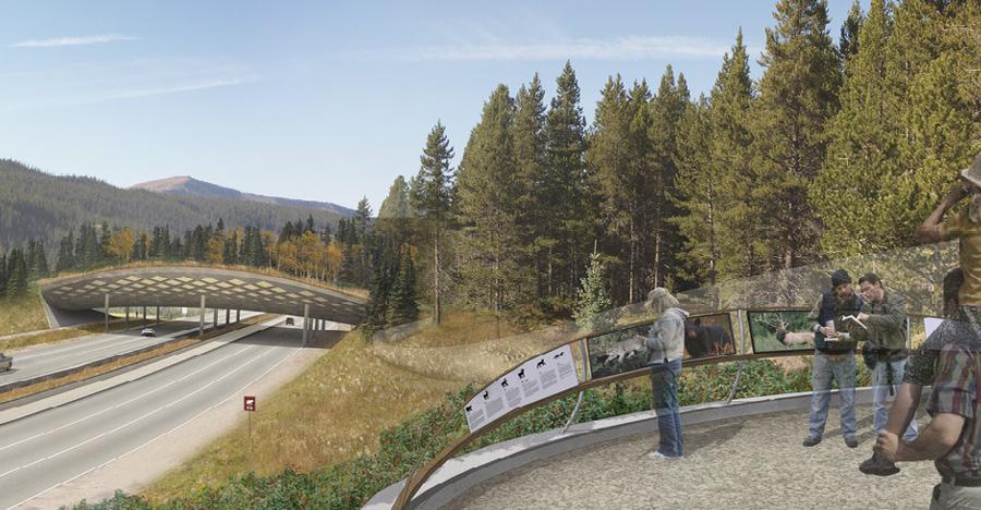
EXTERIOR OBSERVATION DECK
LAND BRIDGE AXON COMPONENTS
The bridge axon structure show the process and components of the materials utilized on the bridge. It helps represent its diagram pattern and its reason why it was used in such a way. The land bridge axon components diagram identifies the components of the vegetation on the bridge. This illustrates how thick this land bridge becomes. Both diagrams help combine both structure and natural vegetation.
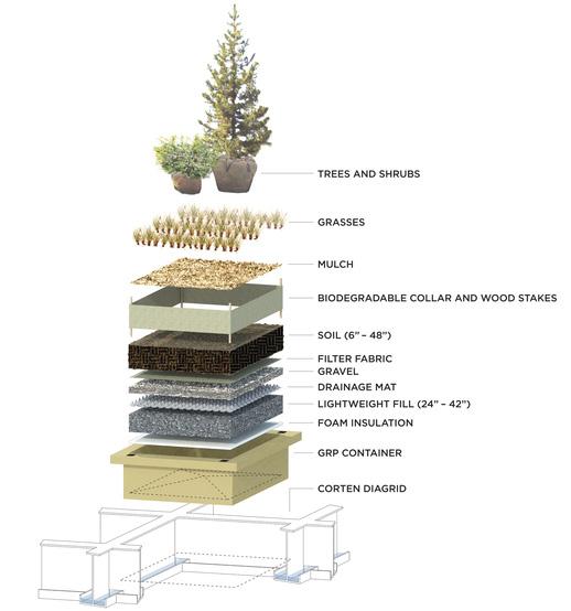
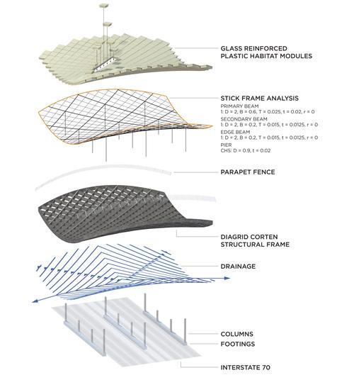
In a way, an exploded structure axon conveys many design elements. These diagrams would be a concept to my projects diagrams. This would show how my structure of the bridge came to be and how the vegetation is incorporated into the land bridge.
The image to the left is shows the bridge form from a distance. The outlook post is a beautiful statement that land marks the bridge. This observation deck is also great in educating people about the wild life that crosses the bridge or that live around the area. The structure creates a link to respond for the ecological wild life on either side of the highway.
Lastly, this rendering inspires me to create an image where water and building are both celebrated. A render on the far end of the pier looking back on to the building and seeing people fishing, taking pictures or canoing. Also at the time of day where the sun would be going down, having light from the building shine its way through.
45HTTPS://WWW.THEOLINSTUDIO.COM/ARC-WILDLIFE-CROSSING-COMPETITION
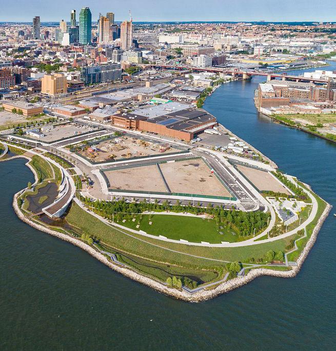
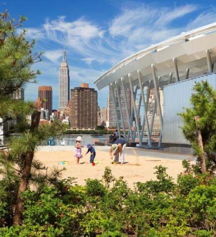
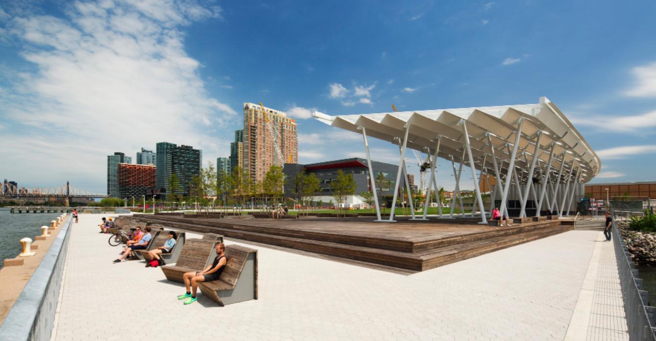
Hunter’s point is a project that helps the user get away from it all. Its incorporation the water front creates a sanctuary with the city being on display. Its place making on the site create elaborate site views and interactive spaces. It becomes a cultural destination. The park would invite communities by providing open spaces like trails, lawns and parks along the water. It’s a push for a multitude of sustainable initiatives.
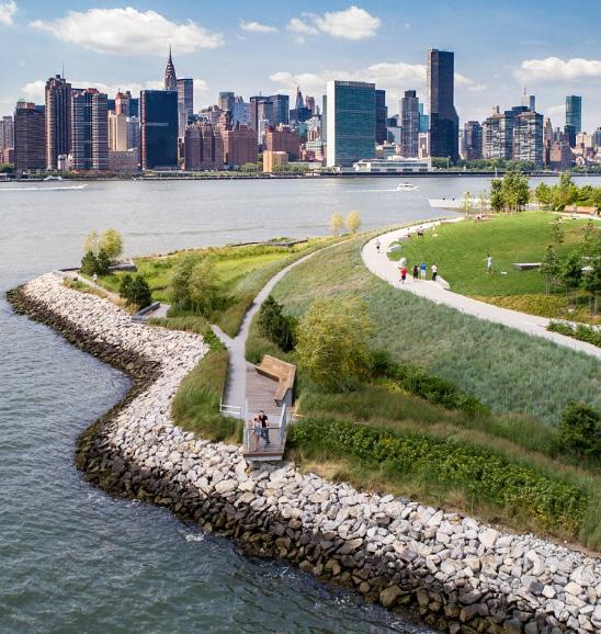
To conclude this project is a huge help for pushing my designs to think about the urban fabric. How I could reach into the landscape and create beautiful spaces where interaction occurs. Play spaces, resting places and infrastructure interaction.
46 HUNTERS POINT PROJECT: Hunters Point South Waterfront PROJECT TYPE: Public Park SIZE: 1.5 Acres LOCATION: Queens, New York COST: $66 Million DESIGNER: Weiss/ Manfredi AWARDS: See Link Below DATE: 2018 HTTPS://WWW.WEISSMANFREDI.COM/PROJECTS/15-HUNTER-S-POINT-SOUTH-WATERFRONT-PARK
BEACH / PARK
OBSERVATION DECK/ PIER
PERGOLA + VIEW DOCK
The sustainability section diagrams embellish how solar gain and water collection occurs. From the section the angled form of the pergola allows the panel to sit at the right degree in order to collect solar energy. The pitch of the pergola allows for water to flow from one high point down to the lowest portion. The water then spills into a small water way which would replenish the aquifer. The image to the left represents a great culmination of structure and site work.
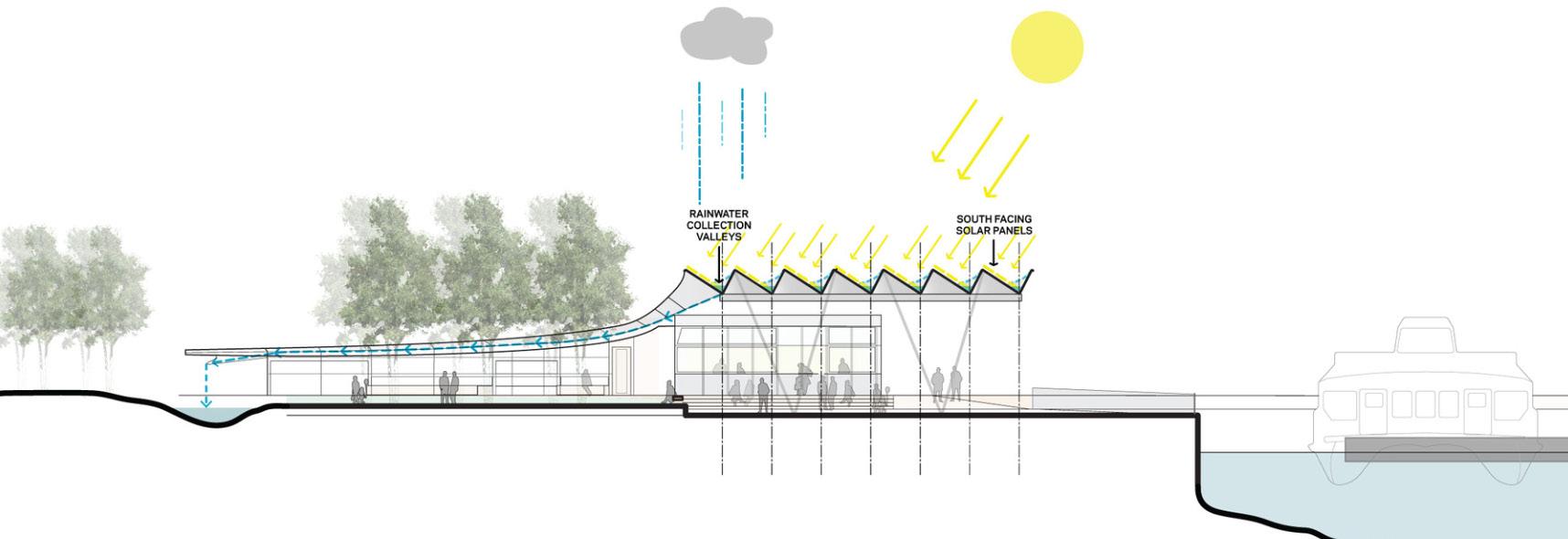
The image and diagram create a great narrative to what my site would need. For diagrams, a section showing sustainable features would be of use. Showing how my design and site would apply these systems.
47HTTPS://WWW.SWAGROUP.COM/PROJECTS/HUNTERS-POINT-SOUTH-WATERFRONT-PARK/ SUSTAINABILITY SECTION
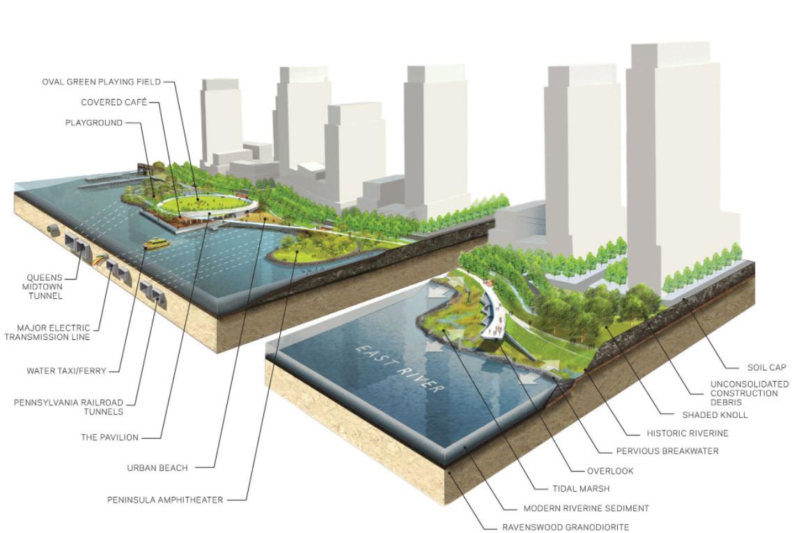
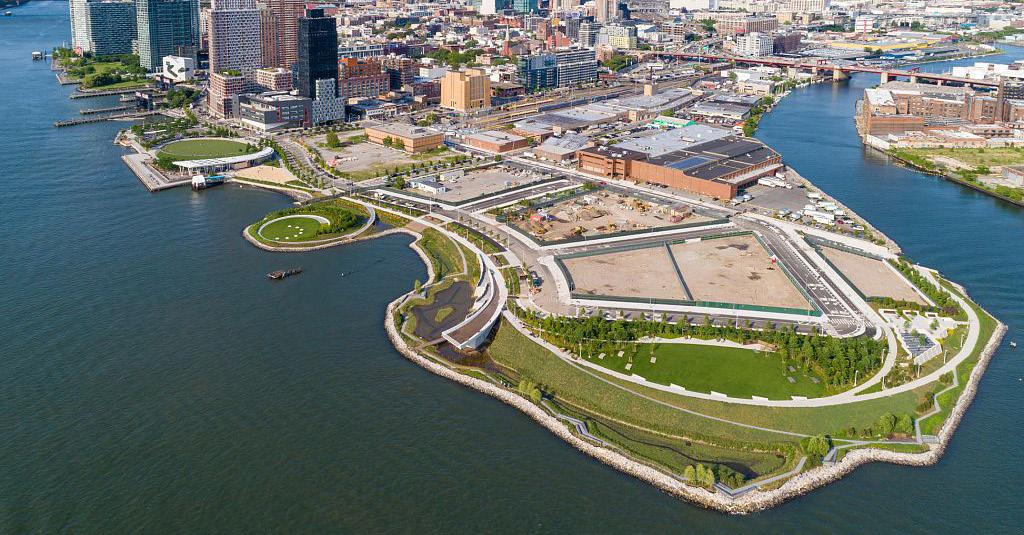
48 SITE AXON SECTION CUT HTTPS://WWW.ARCHDAILY.COM/428013/HUNTER-S-POINT-SOUTH-WATERFRONT-PARK-THOMAS-BALSLEY-ASSOCIATES-WEISS-MANFREDI?AD_SOURCE=SEARCH&AD_MEDIUM=PROJECTS_TAB
The site axon section cut clearly diagrams what recreational uses where designed around the site. This shows how the site was designed in order to protect itself from flooding. Also some areas were also designed for the site to flood in certain occasions. The diagram helps illustrate where the many view corridors are placed. Its elaborate site work with topography becomes an asset in creating outlook piers and winding pathways.
To finalize, the rendered diagram strongly illustrates the many site components that were added. The call outs help signify what I’m looking at. This would help me in diagramming my site plan in the same manner. Showing the many important spaces through the project.
The conceptual sketches sets a foundation of how they started. These sketches are a representation of layering multiple disciplines. Infrastructure, architecture and landscaping. This meshing of ideas in sketch form eludes to some of the final design elements in and around the project.
In conclusion, celebrating concept sketches and showing what and how some designs came to be is very important to me. It would help the reader understand why I did certain design moments in the project. It would show how I had to analyze the site and infrastructure of the building the both relate to one another.
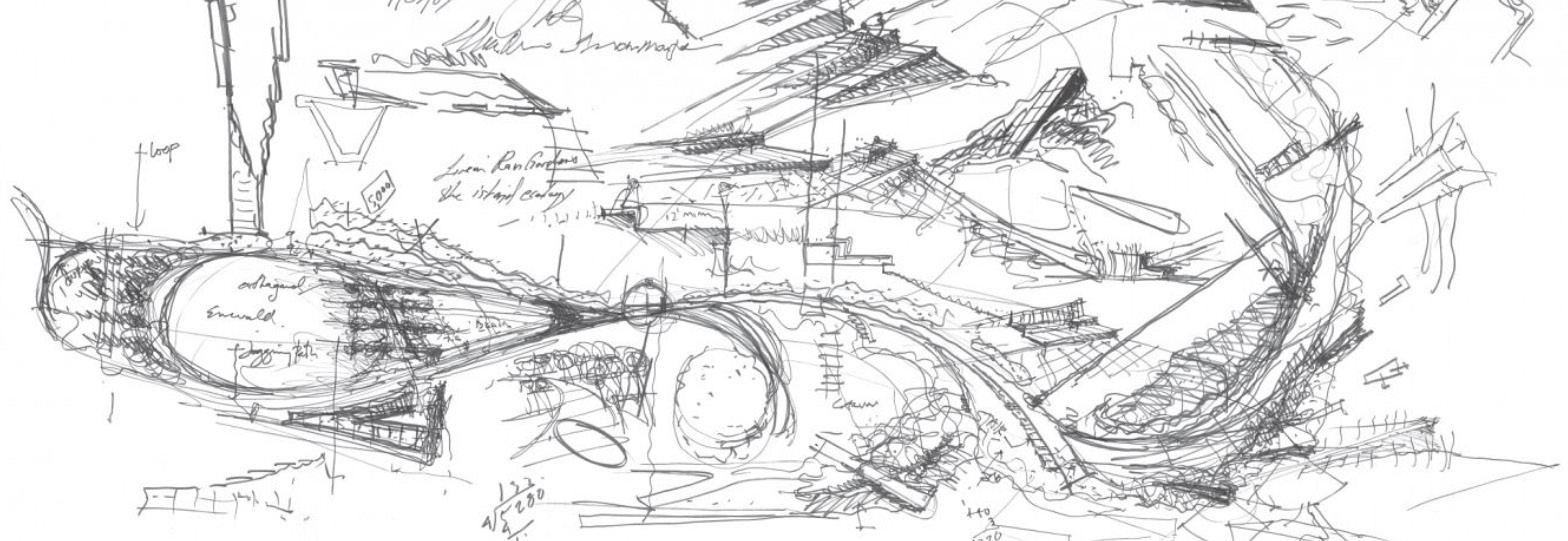
49 CONCEPTUAL SKETCHES
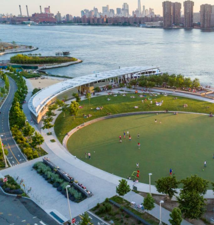
ARIEL VIEW OF PARK
HTTPS://WWW.SWAGROUP.COM/PROJECTS/HUNTERS-POINT-SOUTH-WATERFRONT-PARK/
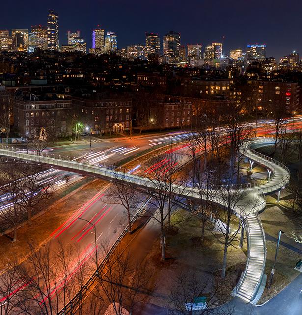
From the beginning of the project their intentions were to improve the connection from Beacon Hill neighborhood to Hatch Shell and Espanlade side. This design was to help improve connections towards the Charles River Reservation. Designing for a pedestrian bridge is an amazing idea which helps create a linkage to residential and waterway.
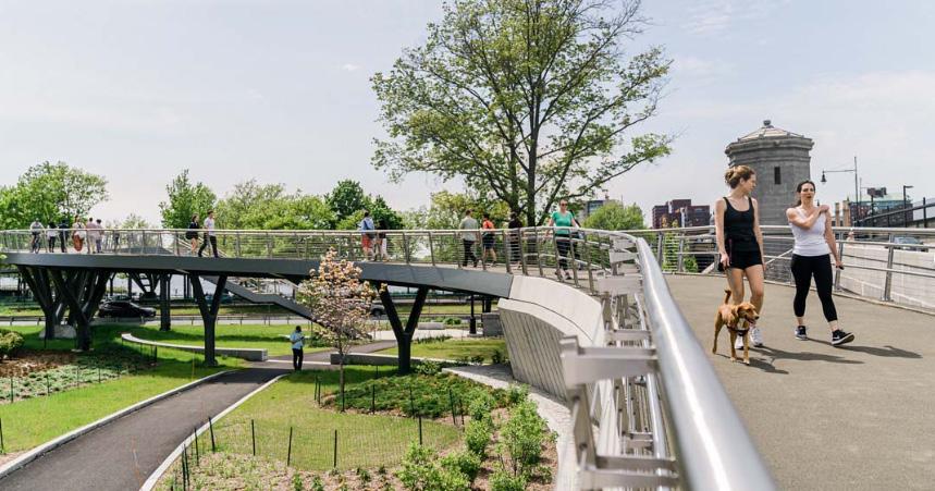
All in all, this bridge best represents community. The ideas that the project presents gives notion to force the community to interact with the waterfront. This helps enforce my design in creating a linkage to combine the residence and the waterfront on my site.
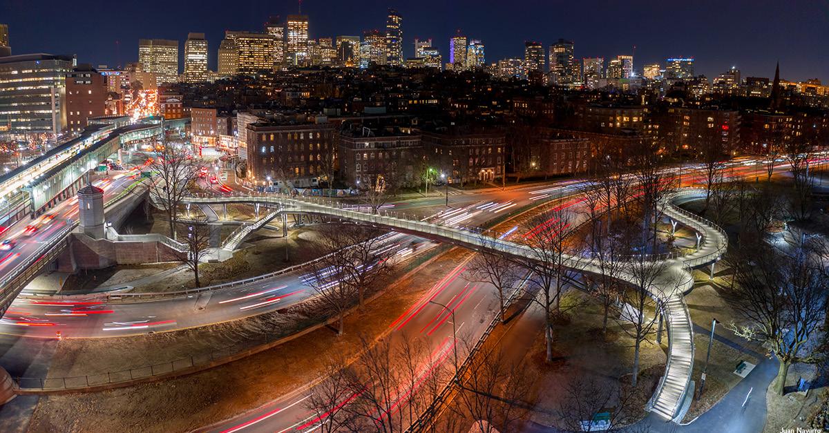
50 FRANCIS APPLETON BRIDGE PROJECT: Francis Appleton Bridge PROJECT TYPE: Pedestrian Bridge SIZE: 10,500 Sft LOCATION: Boston, Massachusetts COST: $ 12,500,00 DESIGNER: Solomon Foundation AWARDS: Arthur G. Hayden medal DATE: 2016 HTTPS://WWW.SOLOMONFOUNDATION.ORG/PROJECTS/FRANCES-APPLETON-BRIDGE/ ENTERING THE BRIDGE
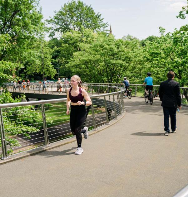
ACTIVITIES ON THE BRIDGE
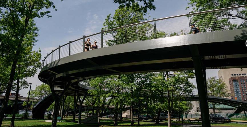
From the bridges successful design and combination of materials and form it is one of the most heavily used pedestrian footbridge. The width of the bridge sits at 14 feet. The length goes about 750 feet. Becoming a massive trail of different view ports and elevations. Its blending of infrastructure and nature incorporate a beautiful narrative of the project.
Generally, the images presented on the page describe the many features in different locations. This precedent is show me how I could push a community to interact with my bridge design. Creating winding paths, outlook areas also incorporating lushes amounts of vegetation. This pooling of users would create a vibrancy towards the water front or on the path.
51HTTPS://WWW.SOLOMONFOUNDATION.ORG/PROJECTS/FRANCES-APPLETON-BRIDGE/
WALKING ON THE BRIDGE
UNDER THE BRIDGE
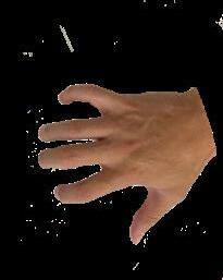
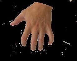
SYMBOLIC PRECEDENT
52
The idea of the hand is to create a good concept idea of how certain features of this part of the body could become part of the building design. The thumb connects to the palm of the hand which becomes the dock, this reaches into the water creating a narrative. The mid section of the hand could become the building. The fingers become an elemental feature/ the ornamentation aspect part of the building. The bones of the fingers would become the structure. The veins could be the plumbing systems of the building the skin could the facade elements. The muscles and tissues would be the other program features throughout a building. As a whole the building would incorporate sustainability features which are impacted by the site.
SYMBOLIC REPRESENTATION

53 SITE ANALYSIS CONCEPT
LEFT HAND CONCEPT
RIGHT HAND CONCEPT
FINAL SYMBOLIC PRECEDENT
INTERACTION COMMUNITY
CONNECTION INTERACTION COMMUNITY
Throughout the semester the original symbolic precedent has changed and morphed to a representation that correlates with both building, site and a land mark element. While listening to many of the reviewers, professors and my fellow peers I took a step back and analyzed the site. Looking at how I could explore the “what the site needs”, to increase pedestrian usage and interaction with elements that cohesively balance building and space. Three words that came into mind while looking at the past precedents becomes the foundation of what I need to design towards. Connection, Interaction and Community. These three ideas signify how I should approach my design. Also how these words could be a design bases for certain spaces.
At the middle of these three words a node. This node would be a representation of a land mark element, a structural column, which symbolizes placement of building. This element becomes the center peace of joining many of the sites elements and programing of the building. Each dashed red line starts to represent design features that symbolically connect to the node.
INTERACTION COMMUNITY
On one of the red lines the land bridge starts to form making its way over the highway. The two other lines split the program. This would help soften the building mass and help spill the program on the waterfront. This splitting of the program would help in creating interactive elements in and around the buildings. The land bridge would start to take shape and morph on some of the buildings program while creating ramps and stair cases. At the center of it all the node, the land mark piece which holds up part the bridge and metaphorically holds up part of the projects design.
54
CONNECTION
CONNECTION REC. 1 REC. 2 MUSEUM CAFELANDBRIDGE
SUMMARY
TRANSPARENCY
Creative Jungle ( p. 14 )
ORNAMENTATION
Versatile Pavilion ( p. 18 )
FACADE INTERACTION
TCDC Khon Kaen ( p. 22 )
STRUCTURAL INTERACTION
Modular Framework ( p. 26 )
PROGRAM SPLITTING
The Connections to Rhodes ( p. 30 )
DOUBLE HEIGHTED SPACE
Active Hub ( p. 34 )
STRUCTURAL EXPRESSION
Pergola in Luotuowan Village ( p. 36 )
FACADE PERFORATION
Lattice Wood ( p. 40 )
ANTI PRECEDENT
Springvale Community Hub ( p. 44 )
CONNECTION
Arch Wild Life Crossing ( p. 46 ) INTERACTION
Hunters Point ( p. 48 )
COMMUNITY
Francis Appleton Bridge ( p. 52 )
55
SITE ANALYSIS
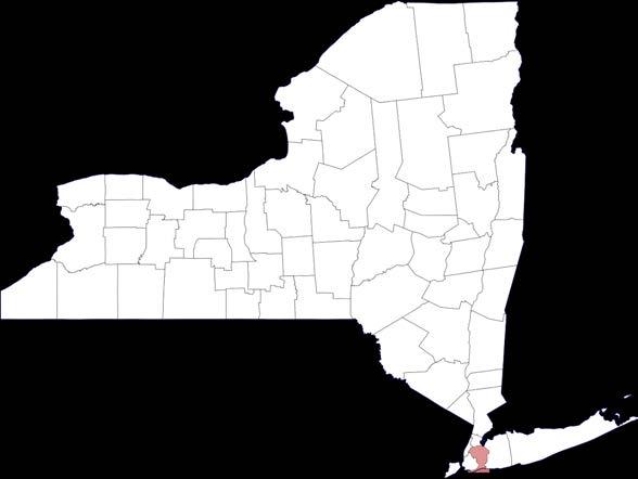


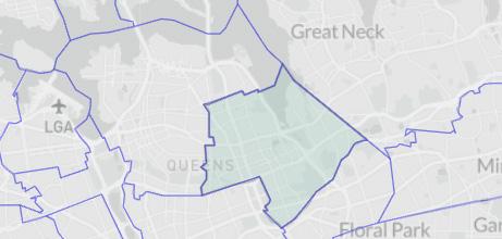
58 SITE LOCATION
UNITED STATES NEW YORK
BAYSIDE, QUEENS, NEW YORK
DOUGLASTON, LITTLE NECK
59
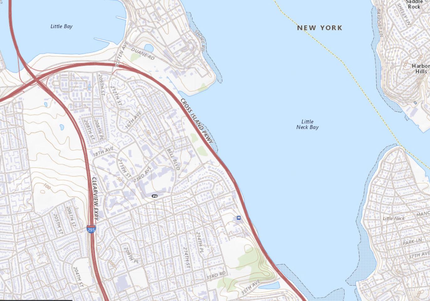
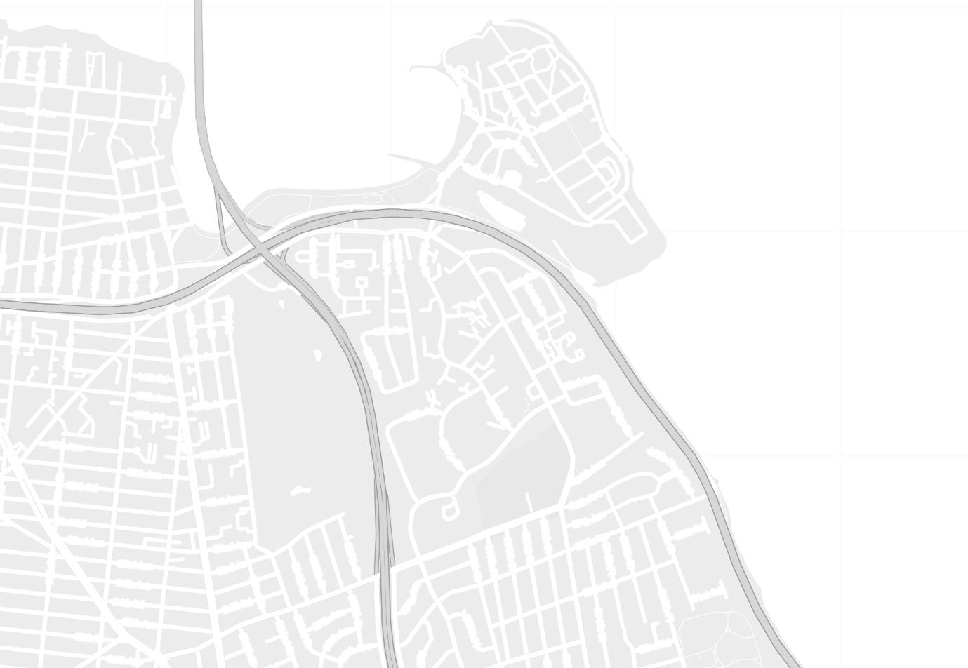
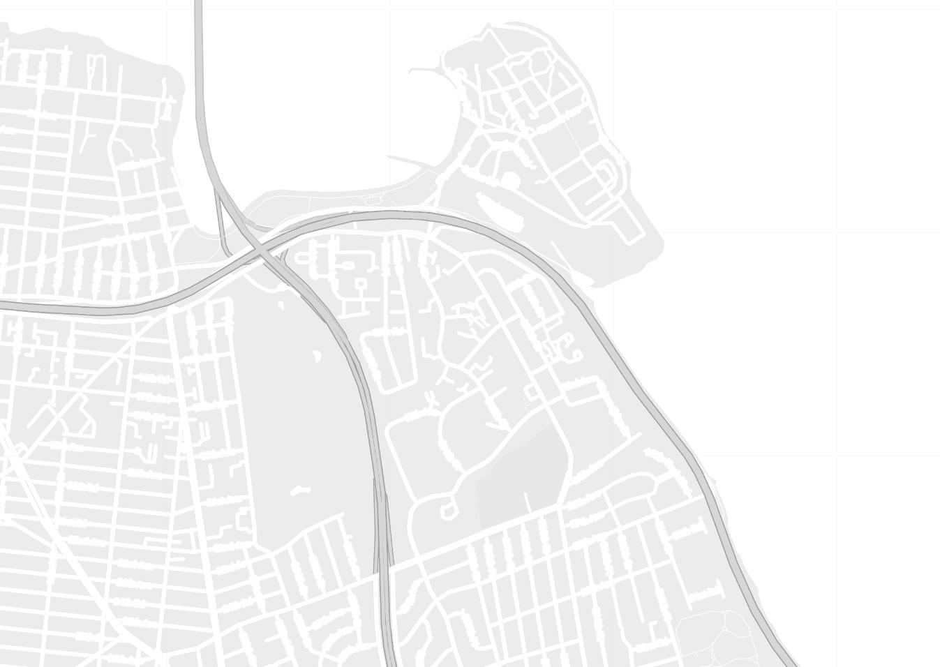
CROSS ISLAND PARKWAY MAP
PLANNING
SITE MAP : BAYSIDE
60
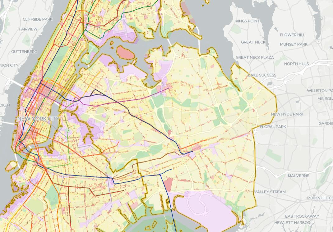
AND ZONING RESTRICTIONS MAP
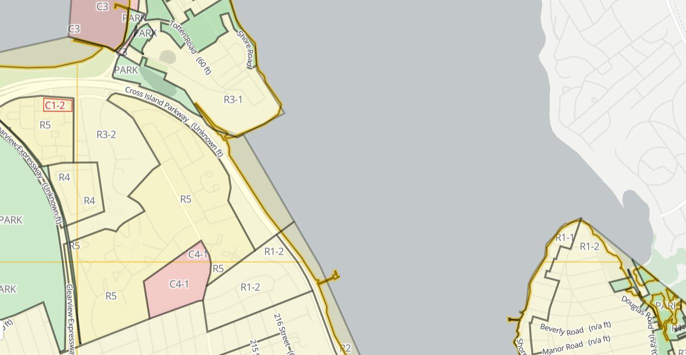
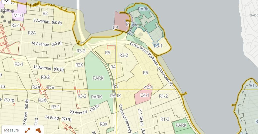
ZONING ZOOM 1
ZOOM 2
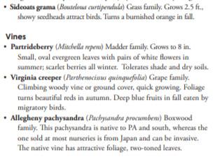
In and around the site there are many different types of zoning restrictions. More so residential zoning.
There are about five different residential zoning types. R1-2, r4, r-5, r3-2 and r-2.
ZONING ZOOM 3
There are three different commercial zoning areas. c-3, c1-2 and c4-1. As well as other areas that are combined or next to park spaces.
The location of the site has no zoning restrictions. But it is applied that since the site is utilizing an untouched green area and is along the water the site then becomes park. This would help in creating a consistency along the water with Fort-Totten being a park and the Marina being a recreational use.
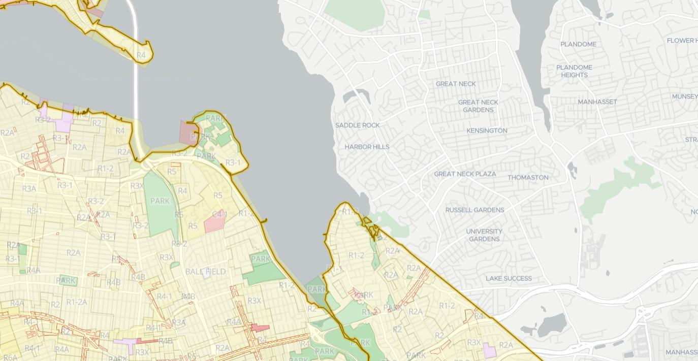
In conclusion the site is allowed to be built on.
61 ZONING
62 TOPOGRAPHICAL STUDY
TOPOGRAPHICAL
Near the water there is an elevation of 0ft- 10ft. Once getting passed the highway towards the residential side hight start to vary from 25ft- 92ft. These charts shows Fort totten sitting a an elevation of 23ft - 59ft. This will help indicate weather I should build high above the water to be aware of flooding around the site. The graphs demonstrate topography telling us how this building could fit on the site. Also how high in elevation it will be.
In conclusion, the site sits a 10 feet above the water level flooding usually occurs at about 6 feet. So there is a 4 feet buffer which would help the building sit dry from any flooding that would occur in the future.
TOPOGRAPHICAL HEAT MAP 2
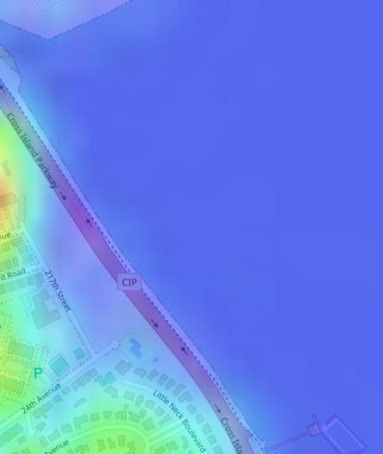
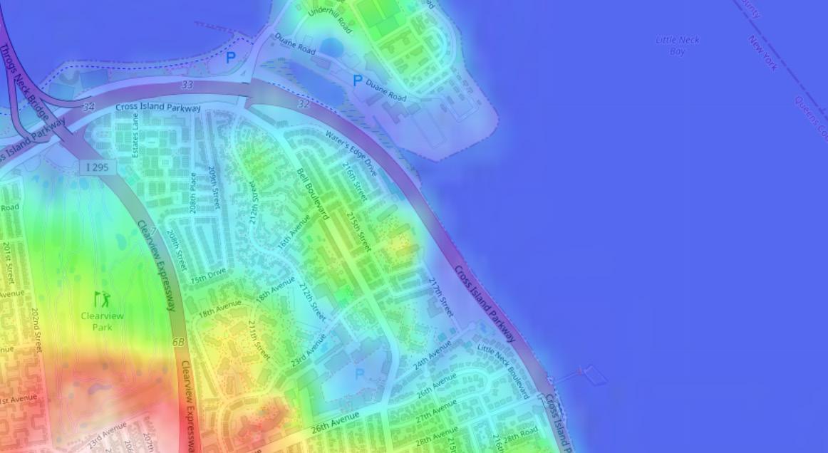
TOPOGRAPHICAL HEAT MAP 3

63
HEAT MAP 1
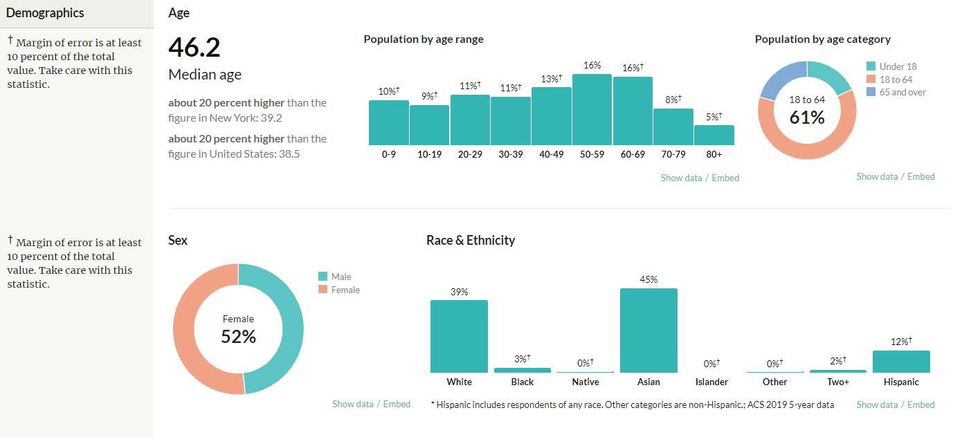
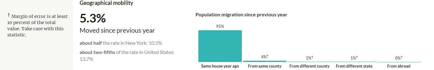
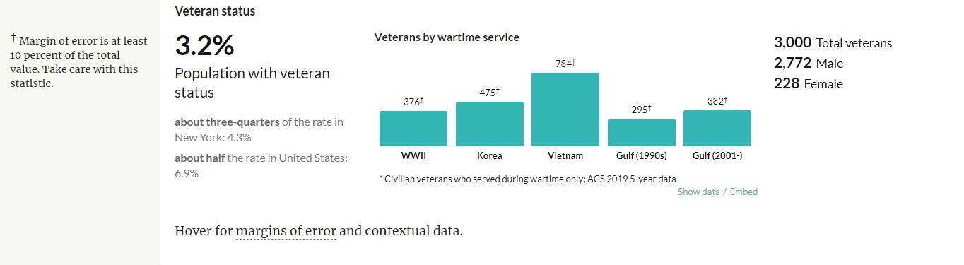
64 DEMOGRAPHICS DEMOGRAPHIC ZONE ZOOM 1 DEMOGRAPHIC ZONE ZOOM 2 HTTPS://CENSUSREPORTER.ORG/PROFILES/79500US3604104-NYC-QUEENS-COMMUNITY-DISTRICT-11-BAYSIDE-DOUGLASTON-LITTLE-NECK-PUMA-NY/
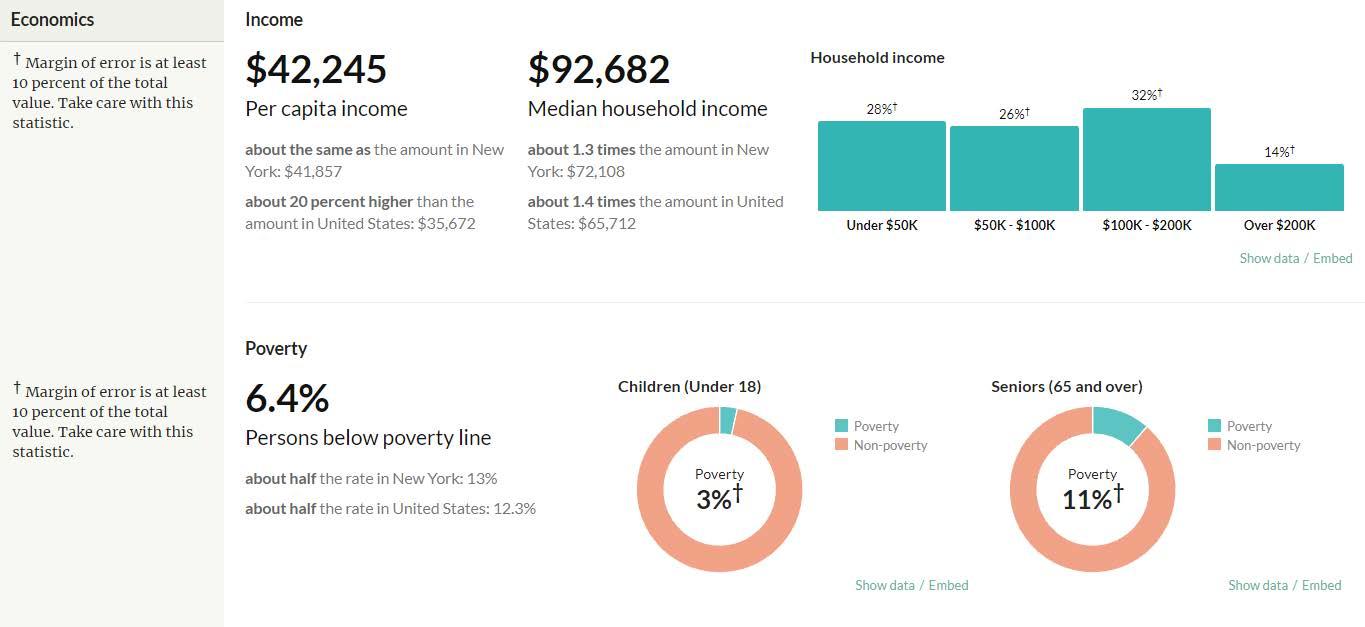
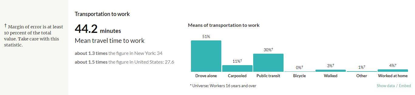
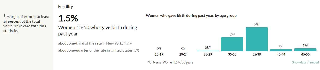
65HTTPS://CENSUSREPORTER.ORG/PROFILES/79500US3604104-NYC-QUEENS-COMMUNITY-DISTRICT-11-BAYSIDE-DOUGLASTON-LITTLE-NECK-PUMA-NY/ ECONOMICS
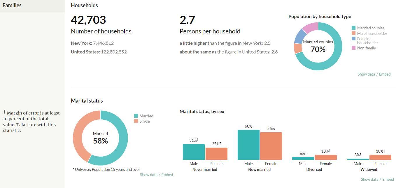
66 HTTPS://CENSUSREPORTER.ORG/PROFILES/79500US3604104-NYC-QUEENS-COMMUNITY-DISTRICT-11-BAYSIDE-DOUGLASTON-LITTLE-NECK-PUMA-NY/ FAMILY HOUSE HOLDS STATUS
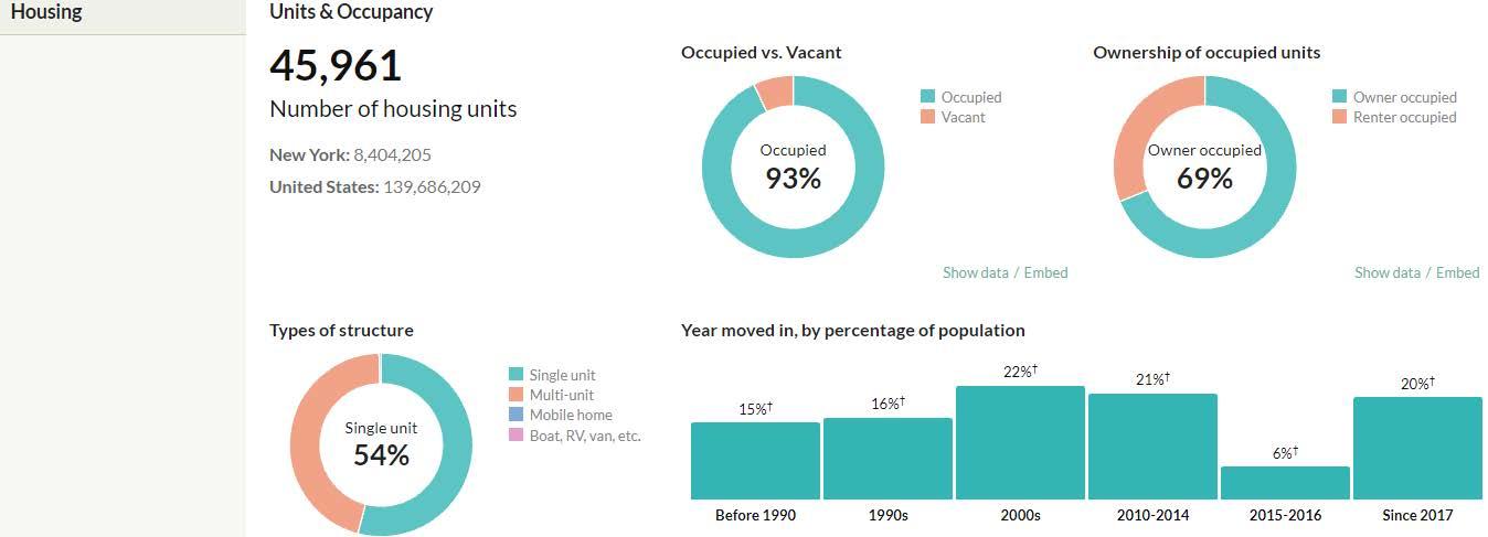
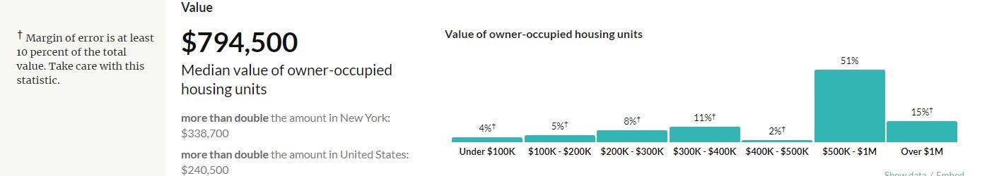
67HTTPS://CENSUSREPORTER.ORG/PROFILES/79500US3604104-NYC-QUEENS-COMMUNITY-DISTRICT-11-BAYSIDE-DOUGLASTON-LITTLE-NECK-PUMA-NY/ HOUSING VALUE
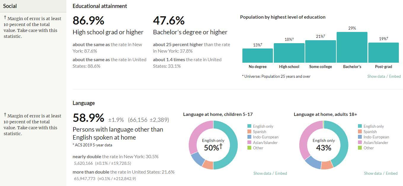
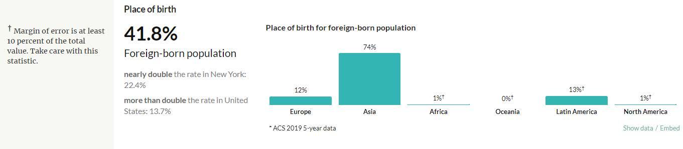
68 SOCIAL STATUS HTTPS://CENSUSREPORTER.ORG/PROFILES/79500US3604104-NYC-QUEENS-COMMUNITY-DISTRICT-11-BAYSIDE-DOUGLASTON-LITTLE-NECK-PUMA-NY/
conclusion, the graphs presented on the current pages give a detailed overview about who is living in the area. This would help my design by creating environments through the project which accommodate for people of all ages. Also creating event spaces that would mirror the type of community that resides in the Bayside, Little neck area.
69HTTPS://CENSUSREPORTER.ORG/PROFILES/79500US3604104-NYC-QUEENS-COMMUNITY-DISTRICT-11-BAYSIDE-DOUGLASTON-LITTLE-NECK-PUMA-NY/ In
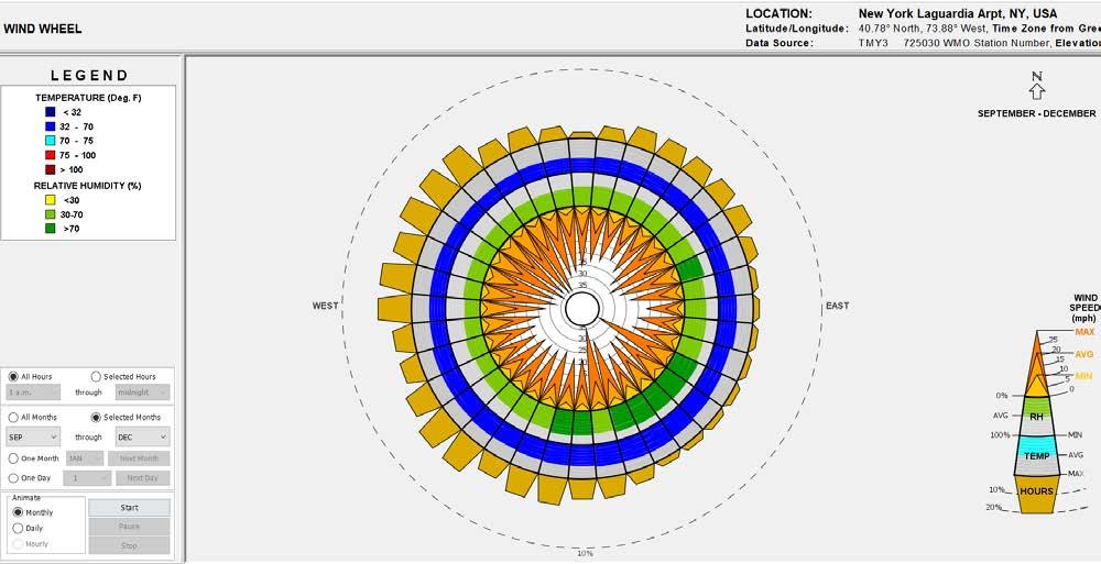
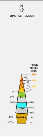
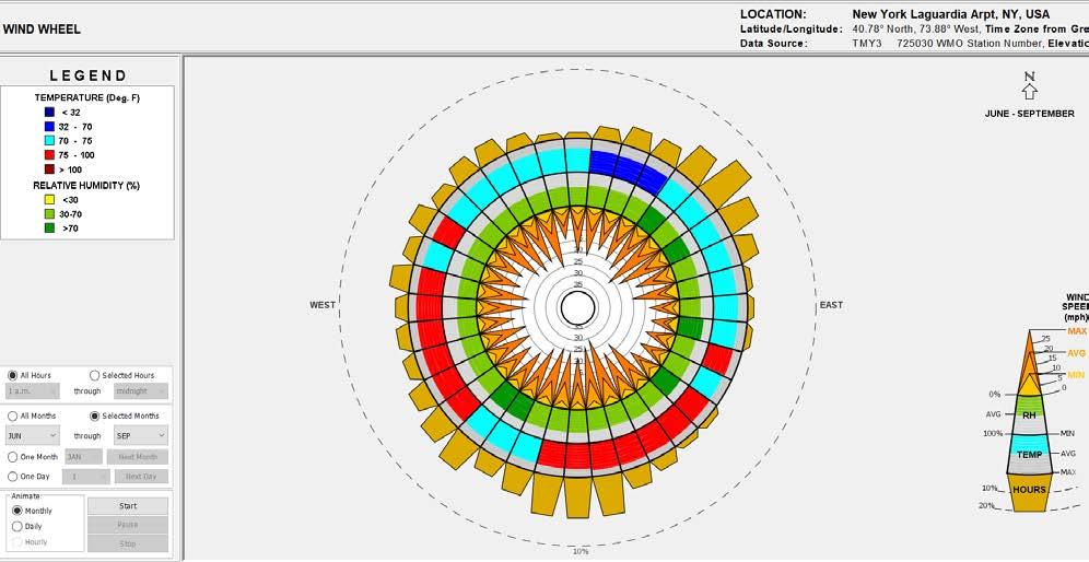
WIND
This chart shows the average wind speed and direction for the months of March - June ( Spring).
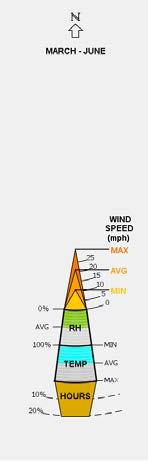
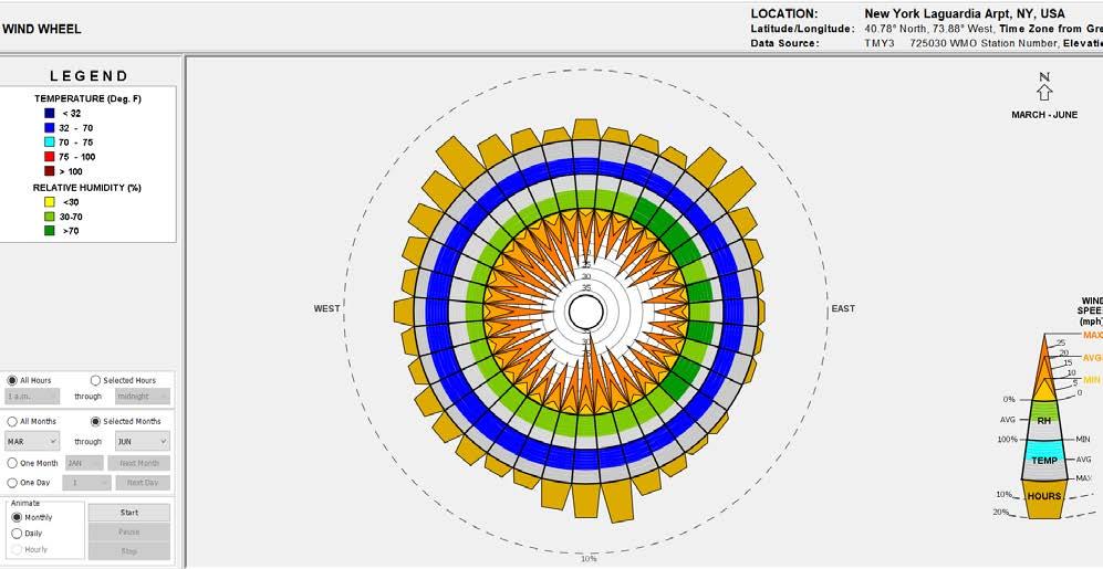
To conclude, a lot of the predominate wind comes from the north west and south east region of the site. The average temperature of these winds are in the range of 32-70 degrees Fahrenheit (cool wind). With average wind speeds at 15 mph.
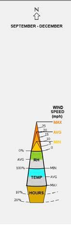
This chart shows the average wind speed and direction for the months of September - December ( Fall).
To conclude, a lot of the predominate wind comes from the western region of the site. The average temperature of these winds are in the range of 32-70 degrees Fahrenheit ( cool wind). With average wind speeds at 20 mph.
70
WHEEL CHARTS
This chart shows the average wind speed and direction for the months of June - September ( Spring).
To conclude, a lot of the predominate wind comes from the southern and north eastern region of the site. The average temperature of these winds on the southern end is about 75-100 degrees Fahrenheit ( warm wind). On the North eastern end of the region temperatures of these wind speeds are about 32-75 degrees Fahrenheit ( cool winds). With average wind speeds at 15 mph.
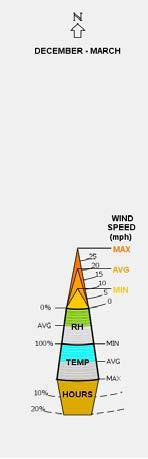
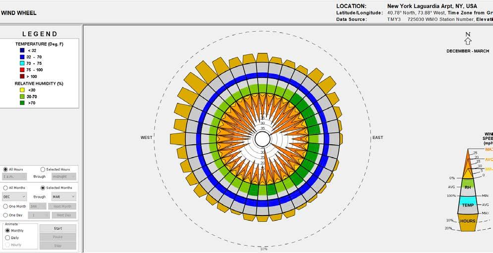
This chart shows the average wind speed and direction for the months of December - March ( Winter).
To conclude, a lot of the predominate wind comes from the north western region of the site. The average temperature of these winds are in the range of 32 degrees Fahrenheit or less ( cold winds). With average wind speeds at 20 mph.
All in all, from the information shown these diagrams help dialogue how my building position becomes very important. The idea is to utilize a lot of the wind speeds throughout the year too cool my building. This would give my building a reason to have operable windows and a adaptive facade.
71
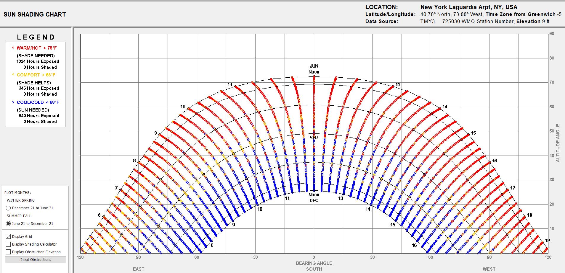
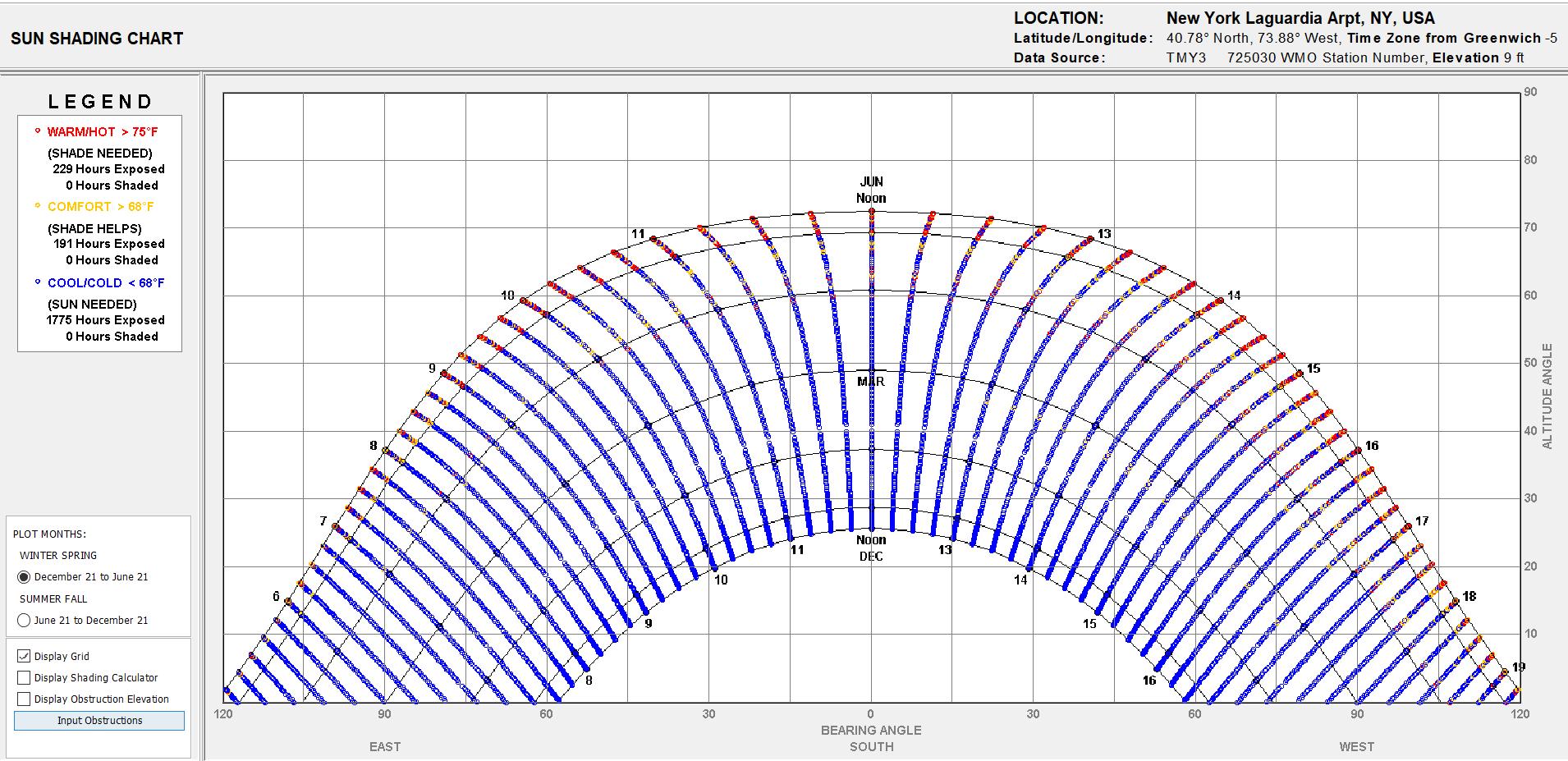
SUN
This chart shows the average shade from the sun in the region of the site for the months of December 21- June 21.
To conclude, during the winter, spring and beginning of summer the sun tends to sit low in the sky hence not receiving a lot of solar exposure. The amount of sun needed is predominate with average temperatures of 68 degrees Fahrenheit or less.
This chart shows the average shade from the sun in the region of the site for the months of June 21 - December 21.
To conclude, during the summer, fall and beginning of winter the sun tends to sit higher in the sky hence receiving a lot of solar exposure. The amount of shade needed is predominate with average temperatures of 75 degrees Fahrenheit or more.
All in all, creating some type of facade screen that allows more of less solar exposure into the building.
72
SHADE CHART
This chart shows the average angle of the sun for the months of December 21 - June 21.
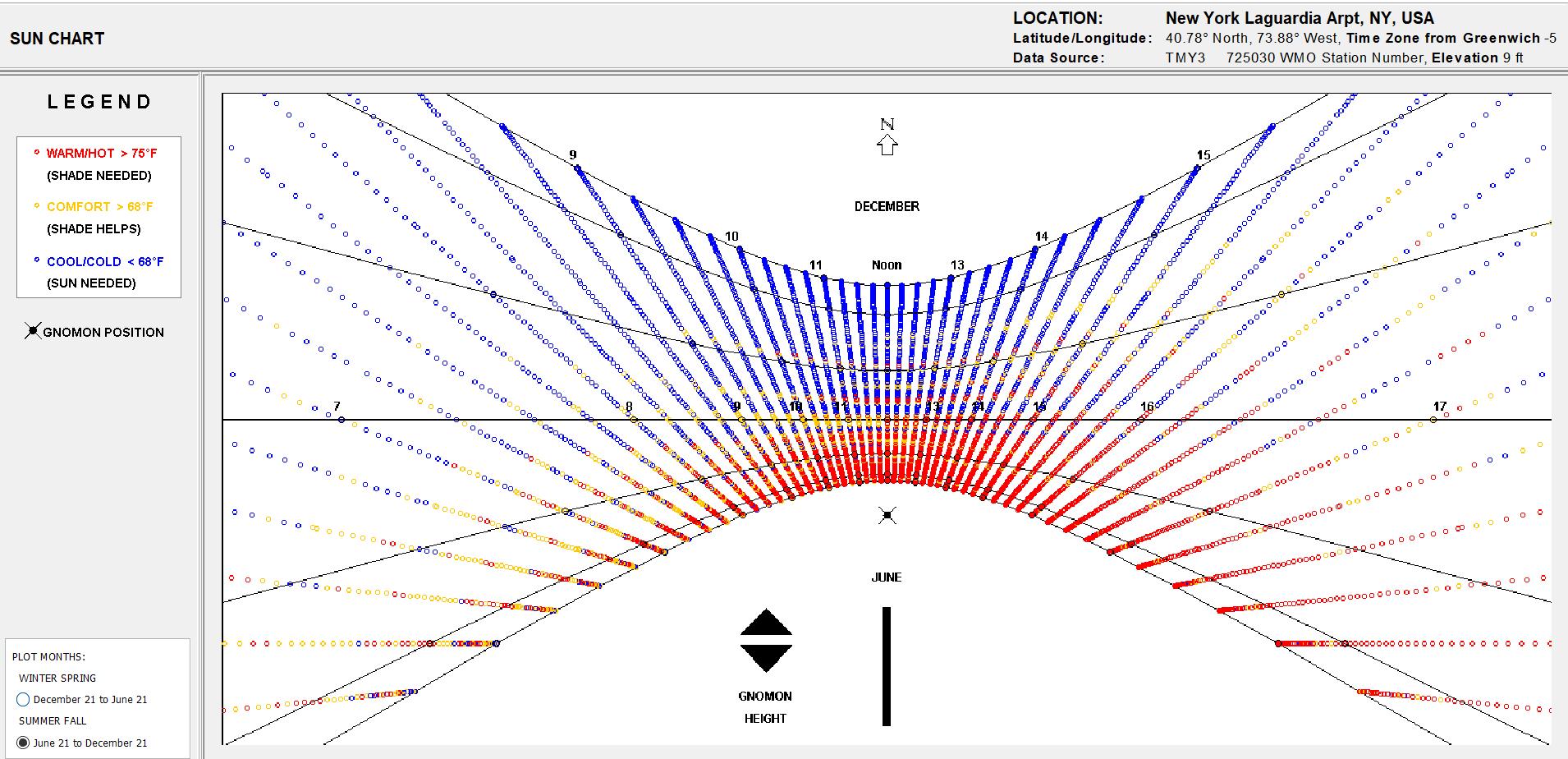
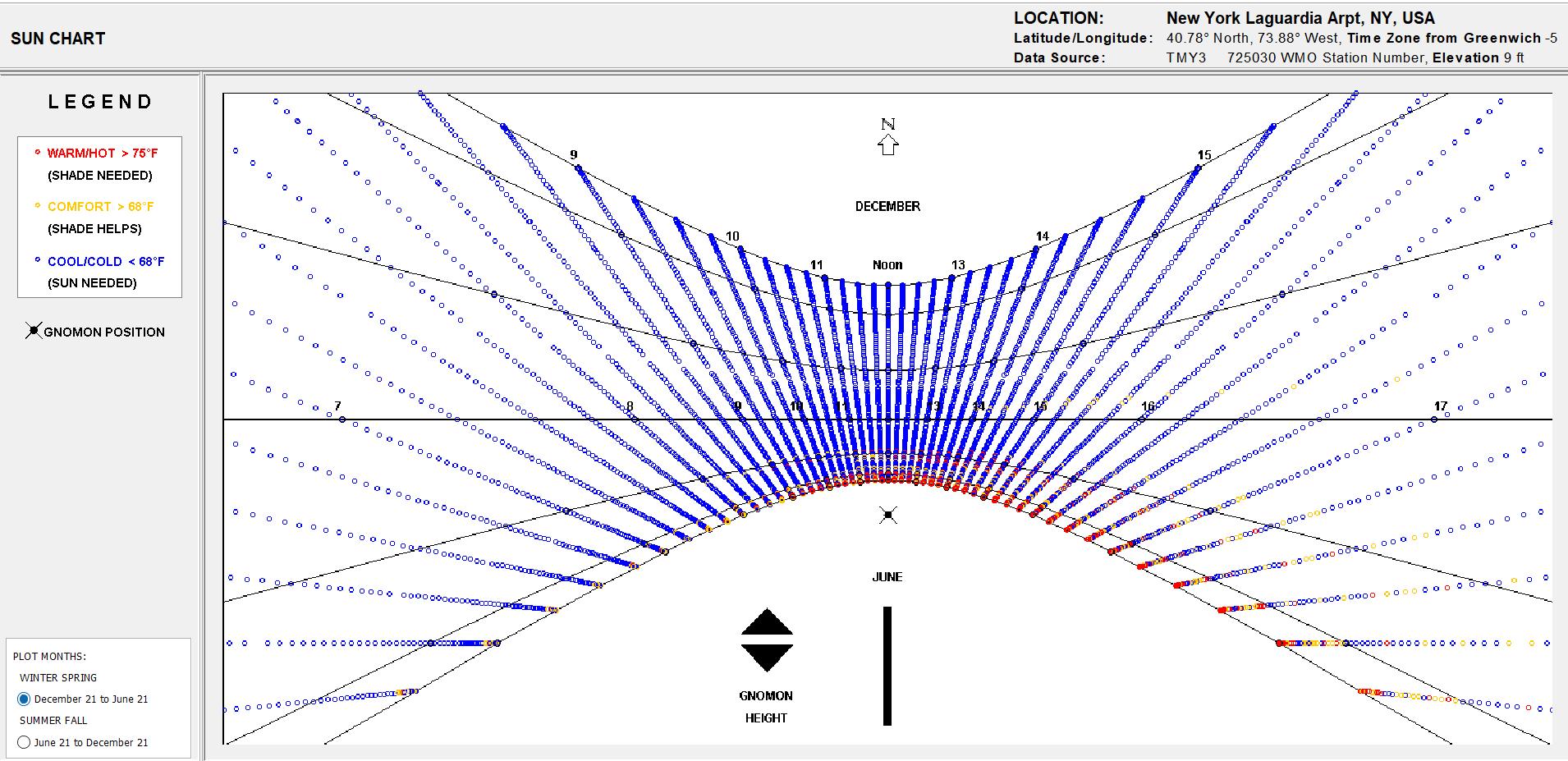
To conclude, this chat helps with locating how far buildings or vegetation comes close to the building site and weather or not the building would be in shade. This portion of the chart shows the cooler months.
This chart shows the average angle of the sun for the months of June 21 - December 21.
To conclude, this chat helps with locating how far buildings or vegetation comes close to the building site and weather or not the building would be in shade. This portion of the chart shows the warmer months.
To conclude, there would be a need for shading elements on the building. Also vegetation element that could be used to help shade portions of the site.
73
SUN CHART
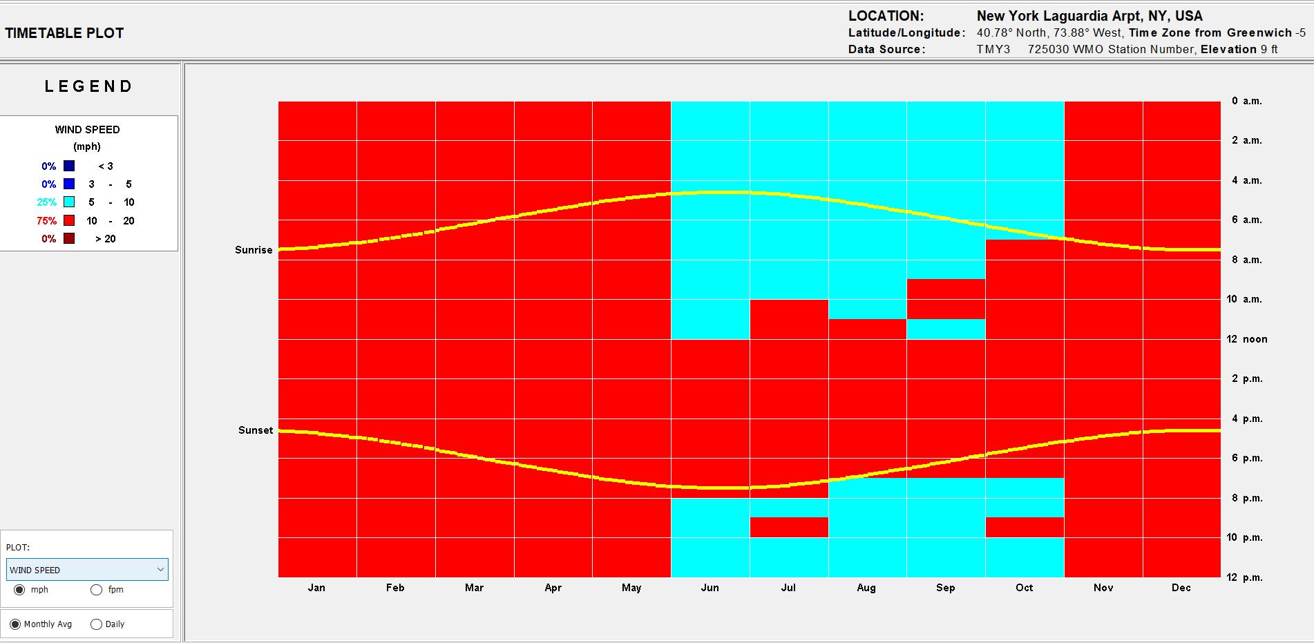
WIND SPEED CHART
This chart shows the average wind speeds throughout the year within the region of the site.
To conclude, this chart shows when and what time of day cooler and warm winds occur from sun rise to sun set.
This chart shows the average wind speeds throughout the year within the region of the site in a 3 dimensional diagram.
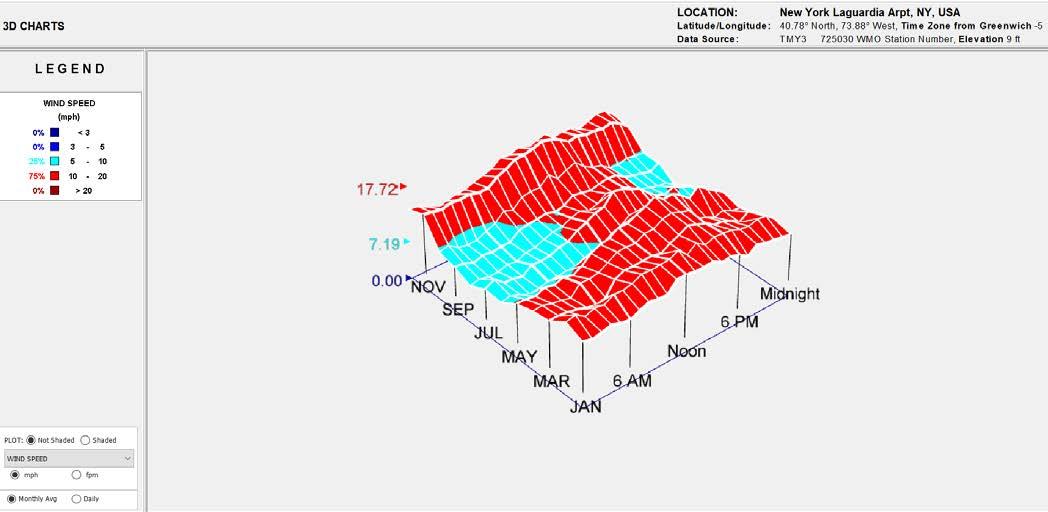
To conclude, this chart illustrates great portions of where warmer and cooler winds occur throughout the year. It also shows at what times these winds tend to be stronger throughout the day.
Over all, having operable winds on the building facade would allow the ability to night purge program. Night purging is cooling the building at night.
74
GROUND TEMPERATURE CHART
This chart shows the average temperatures throughout the year.
To conclude, this chart helps illustrate which moths are warmer or cooler in the year. This would help design a building which could adapt through different temperatures without the over use of mechanical systems. For example, night purging to cool the building during the warmer days and an adaptive facade allowing solar exposure into the building.
This chart shows the monthly average ground temperatures throughout the year.
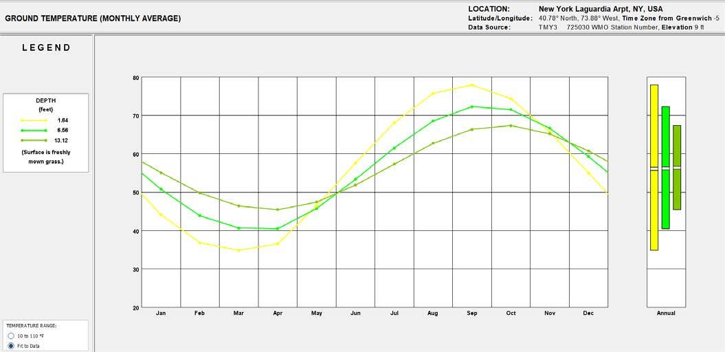
To conclude, this chart is also most helpful in proving that geothermal energy is possible to be achieved. The depth of the ground shows how much cooler or warmer it is. This system would general take the cool months and produce warmer air in the building. In warmer months it would take cooler air to cool the building. This would decrease fossil fuel consumption since its using cooling and heating factors from the earths ground temperature.
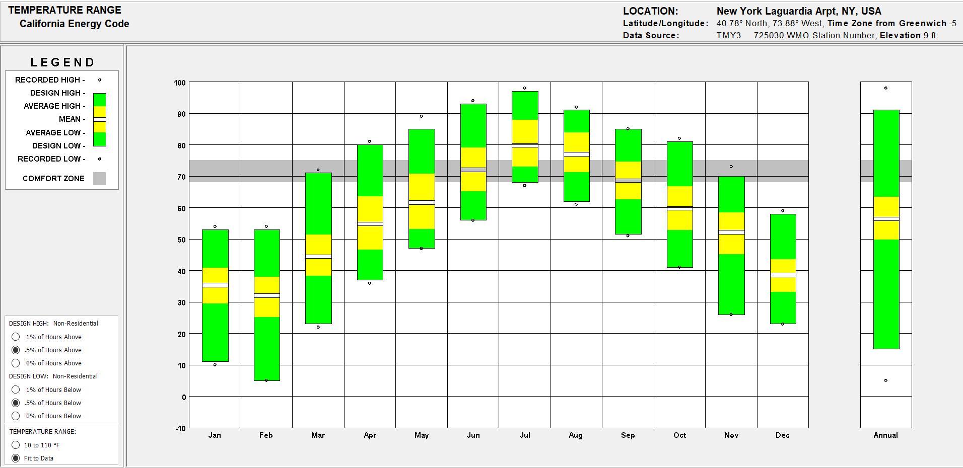
75 TEMPERATURE RANGE CHART
This chart shows the average dry bulb mean, wet bulb mean, hourly dry bulb and the comfort zone throughout the year within the region of the site.
To conclude, this chart illustrates how often the area would receive rain throughout the year. This chart would help prove that using a water collector on the building would sufficiently water the green roof and vegetation around the site.
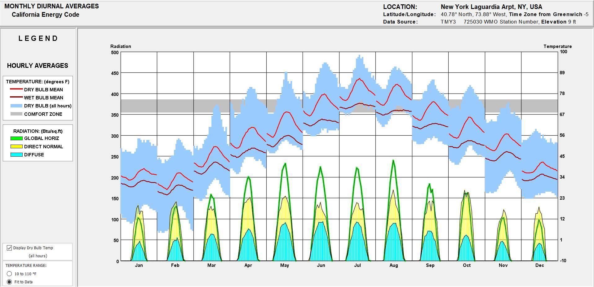
76 MONTHLY DIURNAL CHART
DRY BULB x RELATIVE HUMIDITY
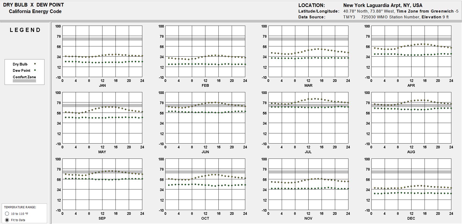
DRY BULB x DEW POINT
This chart shows the average dry bulb and relative humidity in the region of the site.
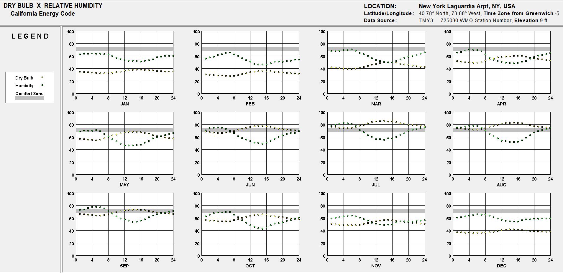
To conclude, it could be seen in the chart when humidity is high in temperature or low. This would relatively help conclude which parts of the year would the outside be cooler in order to cool the building during warm/ humid months.
This chart shows the average dry bulb and dew point in the region of the site.
To conclude, this would relatively help conclude during which part of the year it would rain most often. Know how successful the water collector would work.
77
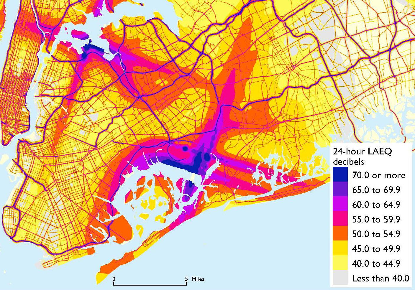
78 SOUND CHART HTTPS://WWW.6SQFT.COM/NOISE-MAP-OF-THE-U-S-REVEALS-NOISE-POLLUTION-IS-WORSE-JERSEY-THAN-NYC/
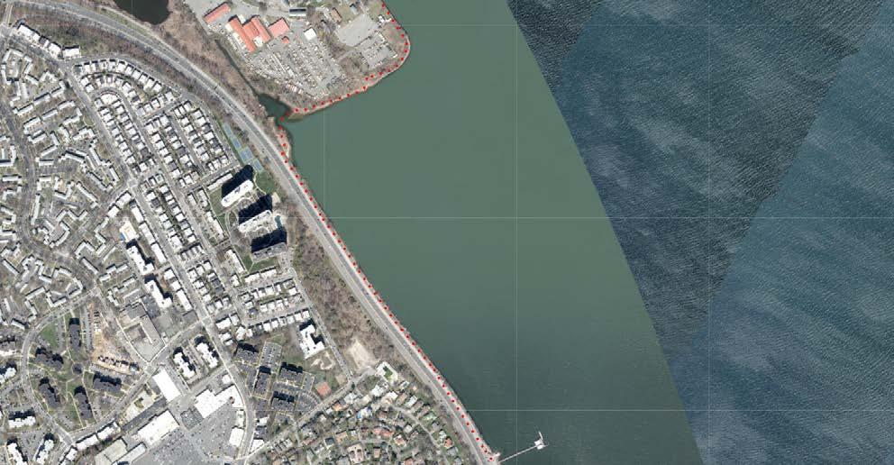
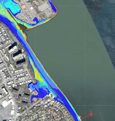
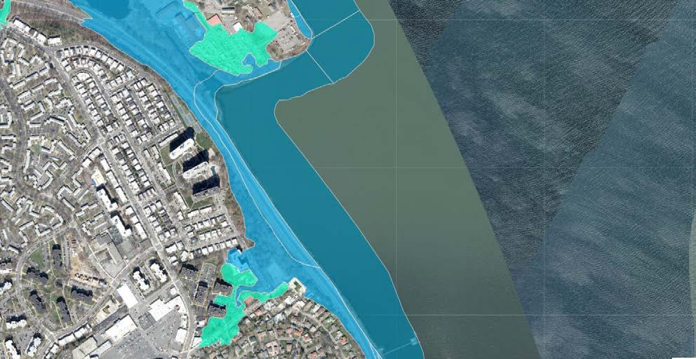
FLOODING MAP
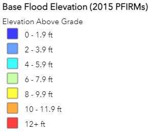
The map to the top left a red doted line shows where the wave could get to a medium high. This is along the pedestrian path. The chart to the bottom left is the area of flooding that would be insured by the government if a reasonable about of damage occurs. The graph on the top right demonstrates the 100 and 500 year flood plain. You may see ranges that go from 0ft - 12ft or higher. Since the building already sits on a high elevation, there wouldn’t be such a problem.
To conclude, the flooding maps help with knowing where I would put water recreational activities to promote fun and play for the site.
79
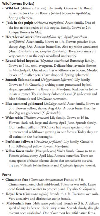
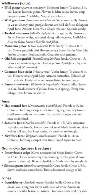
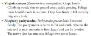
80 VEGETATION HTTPS://NATURALAREASNYC.ORG/MEDIA/PAGES/IN-PRINT/RESEARCH/8CF424230F-1601408873/NRG_PUBLICATION_GARDENING_WITH_NYC_NATIVE_PLANTS.PDF
Above is a list of some of the vegetation that grows naturally in the area. This information would guide me into placing certain type of trees or plants that are current with the site area.
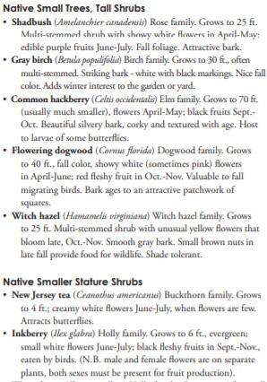
conclusion, creating rendering for the project would make sense if using plants of the right climate.
palm trees)
81HTTPS://NATURALAREASNYC.ORG/MEDIA/PAGES/IN-PRINT/RESEARCH/8CF424230F-1601408873/NRG_PUBLICATION_GARDENING_WITH_NYC_NATIVE_PLANTS.PDF
In
(Not
ZOOMED QUEENS BUS MAP
The maps represent a network of public transportation throughout Queens, New York. The bus that stops near the site is the Q13 line. The Red line is the indicator of the Q13 bus service. This bus line passes/ stops near the LIRR ( Long Island Railroad ) train stop promoting access to and from bell boulevard to Fort Totten. This is indicated by the black circle on the zoomed bus map. The map towards the bottom is the rail line of the LIRR.
All in all, these maps help with locating where the nearest public transpiration is accessible. This all could entice people that aren’t from the area to easily travel by public transportation. If people don’t have a vehicle or don’t want to drive, they have options.
83
LIRR (LONG ISLAND RAILROAD)
BAYSIDE STATION DOUGLASTON/ LITTLE NECK STATION SITE
LONG ISLAND RAILROAD MAP
N 21 St G Court Sq 7 7 G M Court Sq23 St 7 Queensboro Plaza Court Sq CUNY LAW SCHOOL PS 1 MUSEUM 103 E M Q46 LTD makes all stops Q43 LTD makes all stops Q36 LTD makes all stops Q2 Q110 service race days only Q36 LTD make all stops Q43 LTD Q4 LTD makes all stops See Jamaica Inset LIC / Queens Plaza Q83 LTD makes all stops JAMAICA LIRR LIRR BROADWAY LIRR AUBURNDALE LIRR BAYSIDE LIRR DOUGLASTON HOLLIS LIRR QUEENS VILLAGE LIRR LIRR F F F F E J Z E LIRR LITTLE NECK FLORAL PARK LIRR LIRR LIRR BELMONT PARK BELLEROSE Jamaica Van Wyck Jamaica 179 St 169 St Parsons Blvd Sutphin Blvd Sutphin Blvd Archer Av JFK Airport MURRAY HILL G E E R Queens Plaza M 7 N Queensboro F 21 St Queensbridge N 39 Av N W W R W FLUSHING CEMETERY KISSENA PARK KISSENA CORRIDOR ALLEY POND PARK CLEARVIEW PARK CROCHERON PARK BOWNE PARK CLEARVIEW GOLF COURSE DOUGLASTON GOLF COURSE CREEDMOOR STATE HOSPITAL ST. JOHN'S UNIVERSITY GLEN OAKS QUEENS VILLAGE DOUGLASTON LITTLE NECK BAYSIDE ST. ALBANS HOLLIS UTOPIA HILLCREST AUBURNDALE FLUSHING WHITESTONE CAMBRIA JAMAICA ESTATES OAKLAND GARDENS FLUSHING HOSPITAL BELMONT PARK BETH DAVID CUNNINGHAM PARK QNASSAU UEENS ALLEY POND ENVIRONMENTAL CENTER FRESH MEADOWS QUEENSBOROUGH COMMUNITY COLLEGE COLLEGE QUEENS COUNTY FARM MUSEUM BEECHHURST BAY TERRACE BELLEROSE FLORAL PARK ADDISLEIGH PARK FORT TOTTEN LONG ISLAND JEWISH HOSPITAL QUEENS HOSPITAL CENTER HUNTERS POINT GOETHALS AV KENOAV STEWARTRD KINGSBURY AV BELL BL CULLMANAV HENDERSON AV PARK AVE WOODST SPENCERAV FAIRBURY AV EWILLISTONAV LANGDALE ST DELEVAN STCOLFAXST 251 ST 231 ST 181 ST 269ST 251 ST 261 ST 222 ST 153 ST 183 ST 223 ST 147 ST 150 ST 166 ST 170 ST 179 ST 144 ST 215 ST 212 ST 208 ST 212 ST 212 ST 234 ST 248 ST 175 ST 185 ST 195 ST 186 ST 189 ST 196 200 204 ST 194 ST 215ST 218ST 247 ST 258 ST 267 ST 212 ST 210 ST 215 ST 227 ST 208 ST 210 ST 11 AV 9 AV 77 AV 75 AV 67 AV 75 AV 69 AV 64 AV 58AV 58 AV56 AV 50 AV 86AV 59 AV 76 AV 66 AV 60 AV 89 AV 90AV 89AV 104 AV 111 AV 109 AV 100 AV 99 AV 113 AV 88 AV 75 AV 76AV 90AV 89 AV 85 AV 85 AV 79 AV 80 AV 104 AV 110AV 107AV 100 AV 96 AV 115 43 AV 93AV 83 AV 82AV 92AV 82 AV 81 AV 61 AV 91 AV 81 AV 101AVDR 80DR 87DR 82 RD 93 RD 20 RD 94RD 115RD BROWVALE LNRUSHMOREAV 215 ST 216 ST 31 RD 24AV 32 RD 205 ST 169 ST 166 ST 17 AV 18 AV 20 AV 21 AV 23 AV 24 RD 25 DR 17 AV 16 AV MURRAY ST UTOPIA PY 171 ST167 ST163 ST159 ST155 ST 33 AV 32 AV 35 AV 202 ST 204 ST 38AV 36AV 211 ST 42 AV 43 AV 215 PL 217 ST 37 AV 41 AV 39AV 208 ST 156 ST 38 RD 231ST 41AV 41AV 43AV 147 ST HANNIBALST AV 153 ST 156 ST 160 ST LABURNUMAV POPLARAV 39 AV 46 AV 45 AV 53 AV WATERSEDGE DR HENLEY RD DALNY RD ABERDEENRDAVONRD GRANDCENTRAL PKWY 200 ST 106AV THROGS NECK BRIDGE RENFREW ATHERTON AV ATLANTIC AVONTARIO RD CHELSEA ST 112 AV 113 AV 225 ST 115 AV LONGISLAND SSWAYEXPRE LONGISLANDEXPRESSWAY LE CO RPORAL NNEDY ST PARSONS BLVD DOUGLASTON PKWY CROSS ISLAND PARKWAY COMMONWEALTH BLVD LOUISAV SCHOOLRD WESTMORELANDST AV SEWARD AV 17 RD MARATHON PKWY 162 ST157 ST 27 AV 154 ST 157 ST 160 ST 24 AV 22 AV 171 PL 82 DR 84 RD LTD makes ELMONT RD WILLETSPOINT BLVD SERVICE RD NORTH CROSS ISLAND PKWY AV 174 ST JEWEL AV 73 AV 14 AV 101 AV AV GUY R BREWER 95 AV ARCHER AV TUSKEGEEAIRMENWAY POLHEMUS AV 108 AV REX RD 174 ST SAYRESAV 111AV 180ST FERNPL MER ETSBLVDPOINT NS BL V D 149 ST 150 ST 7 AV 150 ST 154 ST 166 ST 160 ST 9 AV C.I.P. 15 AV SERVICE RD S. UTOPIA PKWY FRANCIS LEWIS BLVD BELL BLVD 18 AV 26 AV 14 RD PKWYUTOPIA 23 AV 2 11 ST KE 35 AV 29 AV 32 AV BELL BLVDISLEW I S B DLV FRANC 46 AV BLVDPARSONS HOLLYAV ST SANFORD AV 45 AV 162 ST 165 ST NORTHER BLVDN 150 ST BLVD KISSENA BLVD HORACE H EXARDING PWY UTOPIA PKWY JEWEL AV 71 AV KISSENA BLVD 164 ST UNION TPKE PARSON S BLVD 164 ST 165 ST HILLSIDE AV 188 ST WOODHULLAV179 PL 187 PL CA AVJAMAI LIBERTYAV177 ST 106AV 90AV HOMEL AWNST UTOPIA PKWY 188 ST 188 ST 73 AV HOLLISCOURTBLVD CRO ON AVCHER NORTHERN 216 ST L 48 AV BLVD UKE PL LIT L KWY ENECK 260ST UNIONTPKE73 AV HORACEHARDINGEXPWY M NCIA LN ORE L AS TONPK WY DOUG 56 AV SPRINGFIELD 69 AV 67 AV 230 ST BLVD UNION TURNPIKE S AV 212PL FRANCIS LEWI BLVD HILLSIDE 212 ST SPRINGFIELD BLVD JAMAICA AV BRADDOCKAV JAMAICA AV HEMPSTEADAV HOLLISAV MURDOCK AV 114 AV 113 DR 227 ST SPRINGFIELD BLVDFRANCIS LEWIS BLVDFA BLVD RMERS COLFAX ST 257 ST 256 ST 87 RD 268 ST HILLSIDE AV LITTLE NECKPKWY HEMPSTEADTPKE 10AV NVILLE ST CLI NTO BLVD CLOVERDA BLVDSUTPHIN POWELLS COVE BLVD MARCUS AV LA K E V ILLE RD P T 223 ST CLEARVIEW EXPY CROSSISLAND PKWY CROSSISLANDPKWY CLEARVIEWEXPY 42 RD 41AV VERNON BLVD 11 ST EDKOCH QUEENSBORO BRIDGE 21 ST CRESCENTST 21ST 23ST 37AV 39AV 38AV 31ST40AVVERNON BLVD NORTHERN BLVD THOMSONAV SKILLMAN AVQUEENS BLVDJACKSONAV 43AV 44 DR 43AV 42RD QNSPLZS QNSPLZN 21ST 2 2 46 43 43 28 28 28 30 30 30 30 17 17 17 17 83 83 83 5 4 N 6 N 24 N 24 N 22 N 24 N 6 83 85 84 17 43 N 4 46 N 1 N 1 N 26 83 N 22A 25 25 65 65 65 4 QM 3 QM 3 QM 3 QM 3 QM 2 QM 2 QM 2 QM 16 16 16 16 13 13 13 15 15 12 3 27 27 27 27 27 27 27 36 36 60 1 1 1 88 8888 88 110 110 110 112 110 1 12 1 QM X 68 X 68 X 64 2 QM 1213 46 46 30 X 64 X 68 QM 6 QM 8 QM 5 QM 6 QM 6 QM 6 QM 5 QM 8 QM 5 QM 8 QM 5 QM 8 QM 5 QM 8 QM 5 QM 8 QM 7 QM 7 26 26 15A 15 15 34 46 34 34 60 QM 5 0 QM 2 0 QM 2 0 QM 2 0 QM 2 76 76 76 76 36 36 36 36 36 36 30 42 77 31 31 31 31 31 31 N B 62 102 100 103 101 102 102 2 QM 3 QM 0 QM 2 60 32 B 32 67 102 X 64 X 63 X 68 103 N 20G N 20G 4 QM 4 4 QM 4 2 QM 3 2 QM 3 2 QM 3 2 QM 3 QM 36 QM 35 QM 36 QM 36 QM 35 QM 35 QM 35 QM 35 QM 5 QM 31 QM 31 QM 35 QM 36 1 QM 2 QM 3 1 QM 2 QM 3 QM 4 QM 2 QM 10 QM 1 QM 5 5 QM 1 6 QM 17 QM 10 QM 2 QM 6 8 QM 11 QM 2 4 QM 2 QM 312 QM 34 QM 3 QM 35 QM 360 QM 42 QM 4 N 6 N 6X N 6X N 6X N 22X Queens
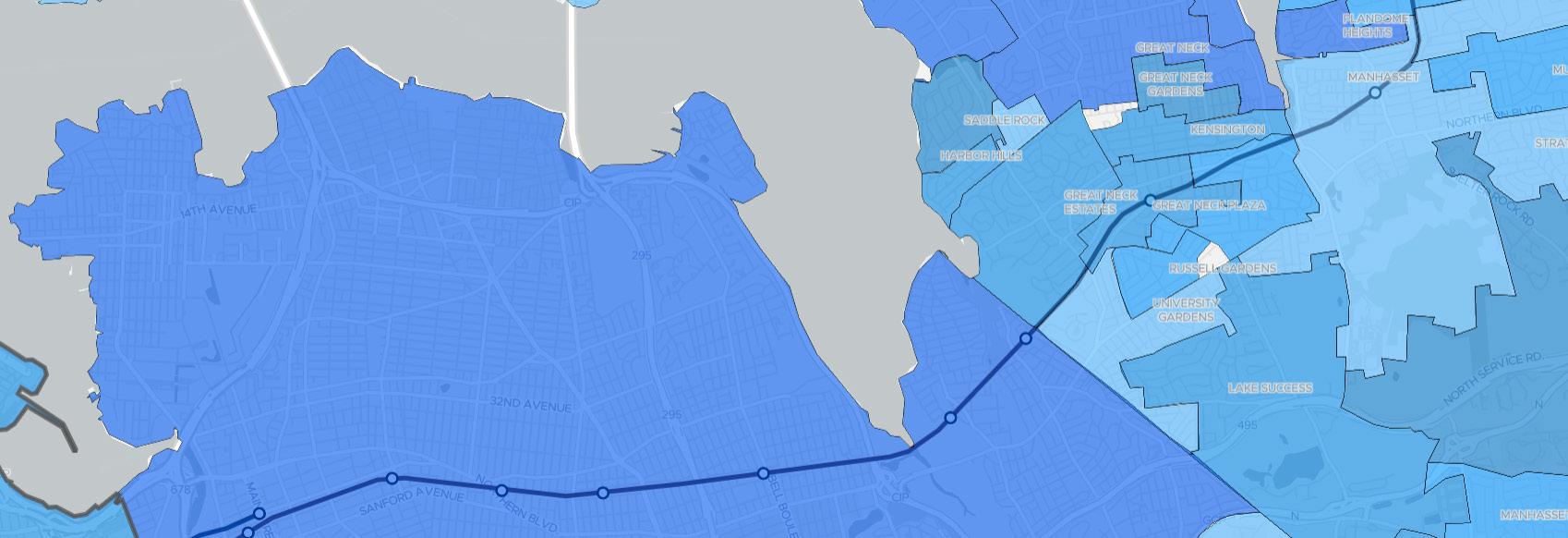
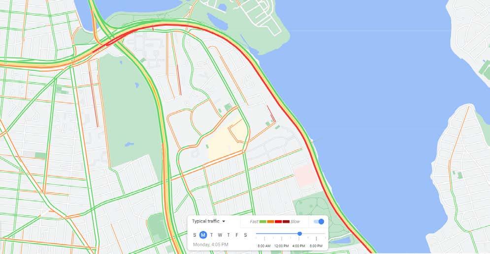
VEHICULAR DAILY TRAFFIC
Monday 4pm
The map addresses traffic flow at certain times of the day. Traffic on a Monday at 4pm coming from Long Island isn’t heavy. Traffic heading towards long island coming from the city tends to be very heavy since many people are already heading home from work of getting out of school.
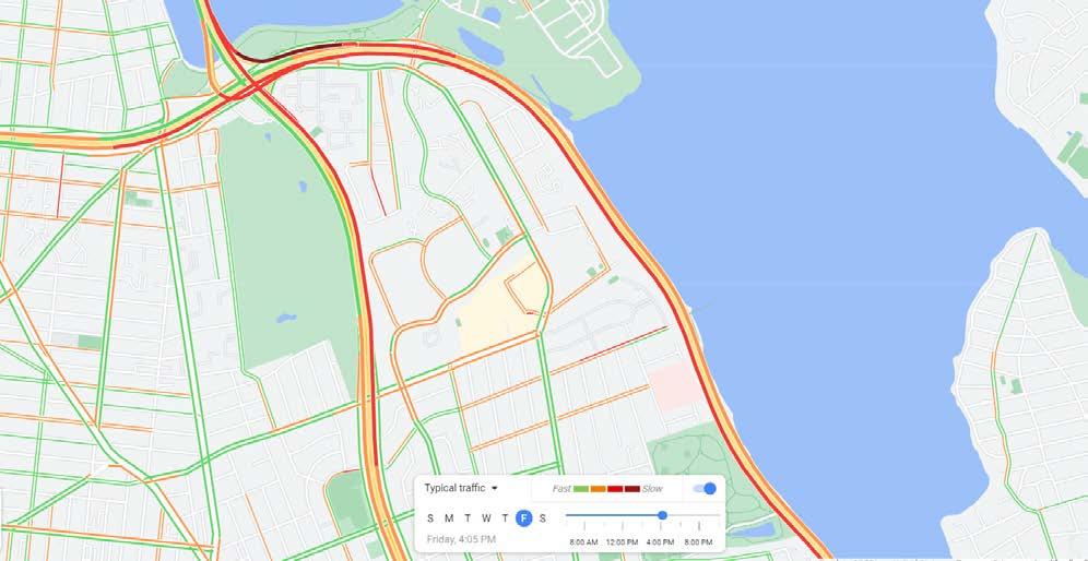
Friday 4pm
The map addresses traffic flow at certain times of the day. Traffic on a Friday at 4pm coming from Long Island is mid heavy. Traffic heading towards long island coming from the city is very heavy. There is heavy traffic on both sides because people could be getting out of work, out of school or traveling since its the start of the weekend.
84
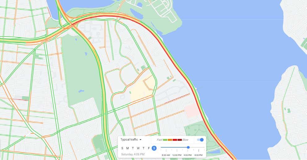
Saturday 4pm
The map addresses traffic flow at certain times of the day. Traffic on a Saturday at 4pm coming from Long Island is light. Traffic heading towards long island coming from the city is very heavy. This could be possible because people could be traveling to beaches, the champions etc for the weekend.
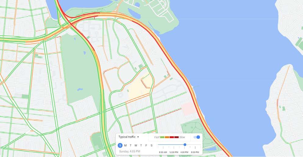
Sunday 4pm
The map addresses traffic flow at certain times of the day. Traffic on a Sunday at 4pm coming from Long Island is mid heavy. Traffic heading towards long island coming from the city is very heavy. This happens because people are traveling back home from any of the activities they went to during the weekend.
To conclude, these diagrams help see how much an influx of vehicular traffic occurs during some of the most busiest time of the day and days. It could be noted that designing a building along the highway would increase traffic hence this could help promote use of public transportation.
85
FORT-TOTTEN
LITTLE NECK
Totten is located along the cross island Parkway due east. Once inhabited by the Matinecock Inidians. During the American revolution it was once called Willets point. Soon became Fort Totten due to the general Joseph Totten in 1788- 1896. Hewas in charge of fortifying the eastern part of the bayside area to the new york harbor. Then it became unused because of the civil war and was used as a place for hospitalization and casualty support. After the wars, this base housed many. Today the base/ park is still being utilized by the department of the army
( also utilized for military schools
spaces). The bayside area was also once a summer resort because of its vast amounts of mansions and its vicinity to the water.
86 HISTORICAL STUDY Shore RdMurrayAv DuaneRd TottenAv Cross Island Py Abbot Rd X Isle Py Et Nb StoryAv PrattAv WeaverAv Bayside St UnderhillRd WhistlerAvLittle Bay Rd Chapel Rd General Berry Rd Ordnance Rd WalterReedRd SgtBeersAv NorthLo TheaterRd WestawayRd EastLo SgtBeersLa CircleDr RedCrossLa LeeRd WilletsSt SylvesterLa OfficersDr WilletsSt Cross Island Py Fort Totten Historic District | LP-2040 Legend Historic District Boundary Building Footprints New York City Tax Lots West Dr East Dr Shore Rd Center Dr Park La 38Rd Manor Rd Arleigh Rd RidgeRd Beverly Rd Marinette St 38Dr HollywoodAv Douglas Rd BayAv Grosvenor St 247St WarwickAv Little NeckPy 40Av Forest Rd 248St 39Av Richmond Rd 255St 41Av Knollwood Av Oak La 239 St Kenmore Rd 34Av 240 St 238 St BayviewAv 37Av Depew Av 233 St 234 St CircleRd Brookside St 36 Av Douglaston Py 249St Sand Hill Rd 38Av Ardsley Rd 233 Pl Cedar La Westmoreland Pl RegattaPl MelroseLa Alston Pl 38 Dr 34Av 39 Av 39Av 37Av DouglasRd Forest Rd Graphic Source: Map PLUTO, Edition 18v1, Author: New York City Landmarks Preservation Commission, LCR Date: 1.29.2019 0.065 Miles[ Douglaston Historic District LP-1957 Douglaston Historic District LP-1957 Borough of Queens Calendared: November 19, 1996 Public Hearing: January 14, 1997 Designated: June 24, 1997 Legend Historic District Boundary Building Footprints New York City Tax Lots
Fort
and coast guard
and event
BellBl Shore RdMurrayAv DuaneRd TottenAv Cross Island Py Abbot Rd X Isle Py Et Nb StoryAv PrattAv WeaverAv Bayside St 209 St 14 Av208 Pl UnderhillRd 212 St WhistlerAv X Isle Py En Sb Little Bay Rd Chapel Rd General Berry Rd Ordnance Rd WalterReedRd SgtBeersAv NorthLo Darren Dr TheaterRd WestawayRd EastLo SgtBeersLa WatersEdgeDr CircleDr Diane Pl RedCrossLa LeeRd WilletsSt SylvesterLa OfficersDr WilletsSt Cross Island Py Fort Totten Historic District | LP-2040 Graphic Source: Map PLUTO, Edition 18v1, Author: New York City Landmarks Preservation Commission, LCR Date: 1.29.2019 0.065 Miles[ Fort Totten Historic District | LP-2040 Borough of Queens Calendared: April 13, 1999 Public Hearing: May 4, 1999 Designated: June 29, 1999 Legend Historic District Boundary Building Footprints New York City Tax Lots
L M K
J
I

A B C D E F
H
87 VIEW OPPORTUNITIES
G
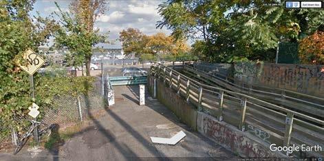
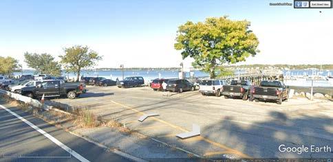
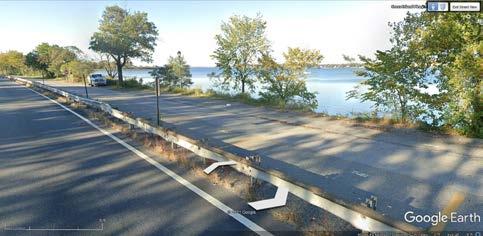
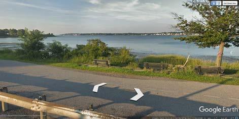
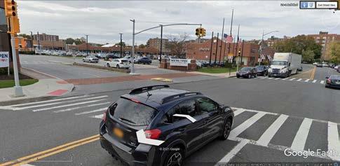
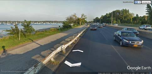
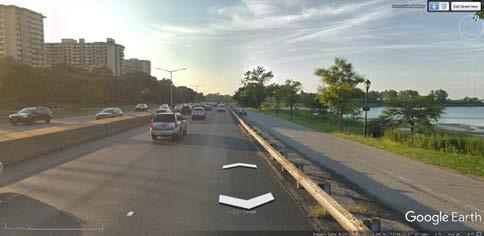
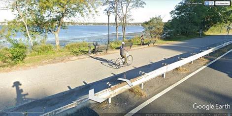
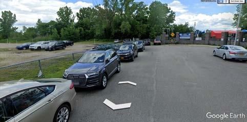
88 A B C D E F G H I SITE IMAGES
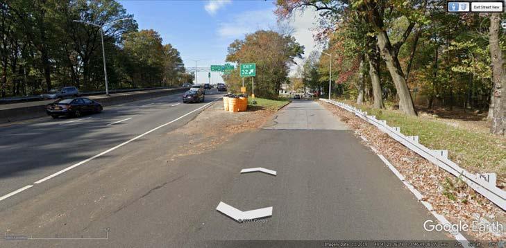
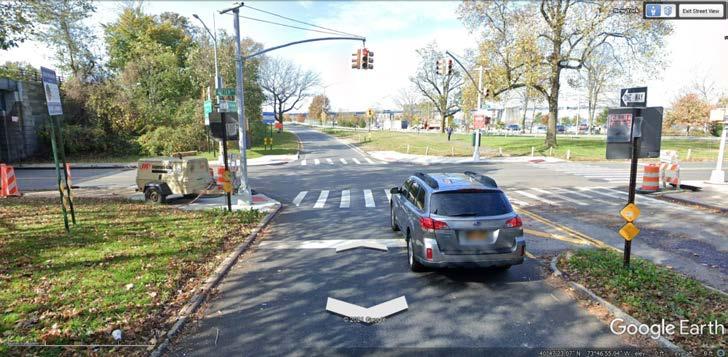
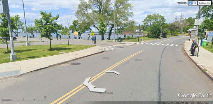
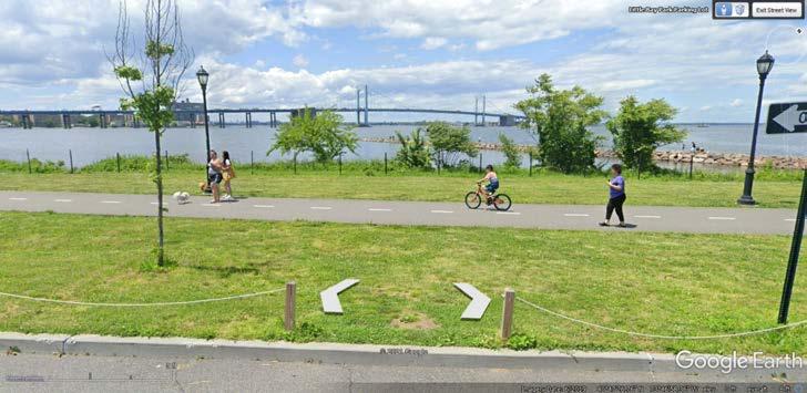
89 J L M K SITE IMAGES
Site Highway Highway exit
entrance

90 HIGHWAY ACCESS
Highway
LEGEND
91 VEHICULAR ACCESS Site Vehicle Circulation LEGEND
PEDESTRIAN ACCESS
LEGEND
Site Pedestrian Circulation
92
Site Bridge connection
Pedestrian Path
Pedestrian site circulation Forested area
93 SITE ACCESS
LEGEND
Fort Totten Military base for the navy. Military academy for training. Also a park for certain events throughout the year.
Forested area great potential for use of circulation through it. A journey through the wilderness and small recreation spaces
Existing pedestrian walkway touching all elements. Becomes an opportunity for building interaction
Secondary streets met with forested area. Opportunity for a path leading across the highway or a journey through the forest. Joining the bridge over the highway
Axial path from shopping centerand bus route to the end of the road. Huge opportunity. How could we get across.
A node essentially a Community hub which touches the water and the pedestrian walkway connects by a bridge. goal interaction, connection and community,the bases of what this site could become. Between Fort-Totten and the marina
Marina Access from highway and existing pedestrian walkway
Cross island parkway, leads to long island, and Manhattan

94 SITE ANALYSIS
0’ 50’ 150’


95 SITE INVENTORY SITE BAY TERRACE SHOPPING CENTRE Q 24 BELL ACADEMYQUEENS PUBLIC LIBRARY AT BAY TERRACE BAYSIDE MARINA FORT TOTTEN MILITARY BASE/ PARK DENTIST/ ORTHODONTIST/ PLASTIC SURGERY/ DERMATOLOGISTRESIDENTIAL BUILDINGS Q 13 BUS STOPS PARK MARINA SITE MALL LITTLE NECK BAY SCHOOL LIBRARY CROSS ISLAND PARKWAY PEDESTRIAN WALK WAY0’ 50’ 150’
CLIMATE
96
ANALYSIS Sun path Solar exposure Wind Direction LEGEND WINTER AT NOON FALL/ SPRING AT NOON SUMMER AT NOON
Overall the ability to analyze the site helps with many questions throughout the design process. Creating the building forms are being based on how it could sit on the site. How the building could create unique experiences based on site evaluation. Also analysis helped me with figuring out what the community needs based on their site program. All in all, this analysis would convey a strong project.
97 SUMMARY
PROGRAM ANALYSIS
13. 3 14. 1 15. 8 16. 2
Could change
Relative to building size
1 20. 1
1
1
1
Could change
1
Could Change
Spaces total sqft
1,750 sqft
3,000 sqft
500 sqft
2,400 sqft
10,000 sqft
2,400 sqft
Could change
Could change
10,000 sqft
300 sqft
480 sqft
Could change
1,080 sqft
600 sqft
154 sqft
140 sqft
Could change
relative to building size
400 sqft
1000 sqft
1000 sqft
400 sqft
144 sqft
Could change
2,500 sqft
Could change
total :
: 576 sqft
: 400 sqft
total : 37,848 sqft
total: 38,824 sqft
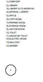
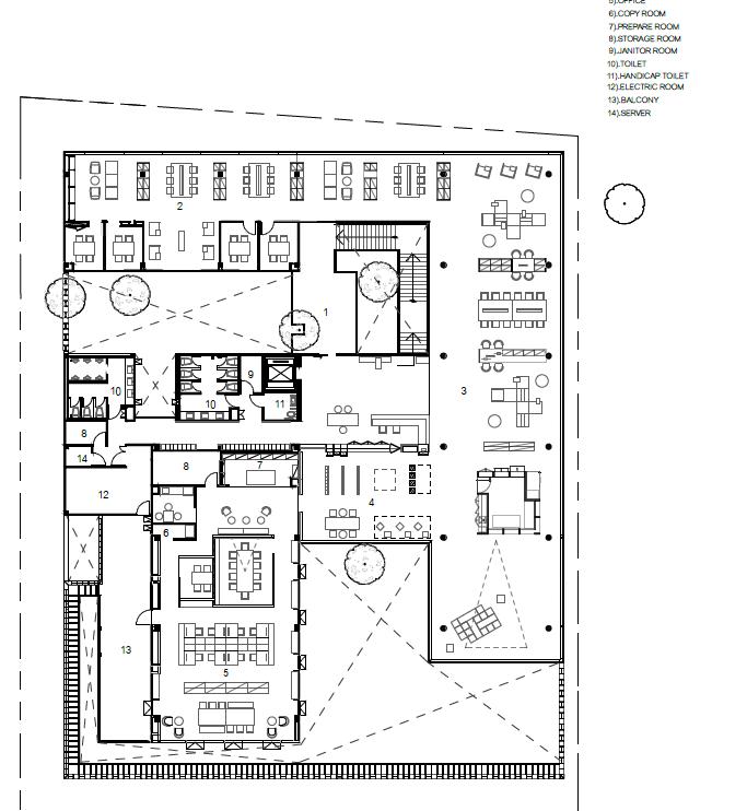
100 PROGRAM LIST Spaces 1. Cafe / Restaurant 2. Digital gallery 3. Entrance reception 4. Learning suites 5. Multi purpose room 6. Community meeting room 7. Amphitheater 8. Integrated public art 9. Library 10. Library reception 11. Offices 12. Storage 13. Bath rooms 14. Library lounge 15. Bike storage 16. Janitor closet 17. Out door play space 18. Pavilion space 19. Electric room 20. Mechanical room 21. Pump room 22. Generator 23. Loading dock 24. Green spaces 25. Observatory/ outlook 26. Recreation space Area 1. 1000 sqft - 1750 sqft 2. 2500 sqft - 3000 sqft 3. 500 sqft 4. 600 sqft - 750 sqft 5. 2500 sqft - 2750 sqft 6. 600 sqft - 750 sqft 7. Could change 8. Could change 9. 10,000 sqft 10. 300 sqft 11. 120 sqft - 150 sqft 12. Could change 13. 360 sqft 14. 600 sqft - 800 sqft 15. 19.2 sqft 16. 70 sqft 17. Could change 18. Relative to building size 19. 400 sqft 20. 1000 sqft 21. 1000 sqft 22. 400 sqft 23. 144 sqft 24. Could change 25. 2,500 sqft 26. Could change Number of spaces 1. 1 2. 1 3. 1 4. 4 5. 4 6. 4 7. Could change 8. Could change 9. 1 10. 1 11. 4 12. Could change
17.
18.
19.
21.
22.
23.
24.
25.
26.
1.
2.
3.
4.
5.
6.
7.
8.
9.
10.
11.
12.
13.
14.
15.
16.
17.
18.
19.
20.
21.
22.
23.
24.
25.
26.
Egress
Elevators
Program
Building
Building
101 OUT DOOR OPEN SPACE ORNAMENTS DOCK AREA EVENT/ PLAY SPACES EVENT/ PLAY SPACESEVENT/ PLAY SPACES INDOOR OPEN AREA GREEN SPACES SUITES SUITESSUITES SUITES BATH ROOM BATH ROOM SR SR MULTI PURPOSE WATER FRONT PEDESTRIAN WALK WAY HIGHWAY CAFE RECIP. MULTI PURPOSE MULTI PURPOSE MULTI PURPOSE GALLERY OFFICE OFFICE FIRST FLOOR
OUT DOOR OPEN SPACE ORNAMENTS
102 SECOND FLOOR
DOCK AREA EVENT/ PLAY SPACES EVENT/ PLAY SPACESEVENT/ PLAY SPACES INDOOR OPEN AREA GREEN SPACES SUITES SUITESSUITES SUITES BATH ROOM BATH ROOM SR SR LIBRARY OBSERVATION OUTLOOK WATER FRONT PEDESTRIAN WALK WAY HIGHWAY RECIP. LIB. LOUNGE LIB. LOUNGE OFFICE OFFICE
Overall the ability to see the program and organize them between the water and the highway helps create portions where the buildings orientation as well as program could be placed. Relationships with other programs help create a cohesive plan with organic circulation. Being able to apply sustainability system from the beginning would create unique space within the building. The reason to having more than one floor is to create a building where the user would have different view ports through space within the building. Also being able to create unique building forms from the give program.
103 SUMMARY
CONCEPT REVIEW JANUARY 28, 2022
FORT TOTTEN MILITARY BASE
PEDESTRIAN WALKWAY
CROSS ISLAND HIGHWAY
SITE PLAN BUILDING FORM


BUILDING
LATTICING
FOOTBRIDGE
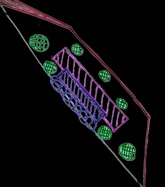
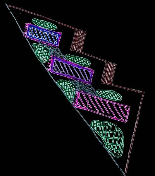
Program fits into the building form with the combining of the cafe and library. the use of interactive spaces and public/ private rooms. Near the pedestrian walkway an opportunity for a unique lattice effect creating a different experience with a structural expressed open corridor. Protrudes into the walk way to entice the user.
106 CONCEPT 1 : THE POINT
MARINA
VIEW POINT DOCK
GREEN SPACES

107 CONCEPT MODEL 1
FORT TOTTEN MILITARY BASE
PEDESTRIAN WALKWAY
CROSS ISLAND HIGHWAY
SITE PLAN BUILDING FORM
STAIRS TO WATER
VIEW POINT DOCK
LIBRARY/ CAFE
EVENT SPACES / OFFICES/ ROOMS
VIEW POINT DOCK
LATTICING
GREEN SPACES
FOOTBRIDGE
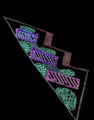
The program fits into these two bars. With the library being places in the back combined with the cafe. In the front bar spaces like your interactive spaces offices as well as the public private rooms. Again protruding into the walkway this structurally expressed lattice or sculpture creating a unique experience on the walkway. And a view opportunity on the highway.
108 CONCEPT 2 : TWIST POINT
MARINA

109 CONCEPT MODEL 2
SITE PLAN
PEDESTRIAN WALKWAY
CROSS ISLAND HIGHWAY
LATTICING
OFFICES/ ROOMS/ MEETING
STAIRS TO WATER
CAFE
BUILDING FORM
LATTICING
STAIRS TO WATER
LIBRARY
VIEW POINT DOCK
GREEN SPACES
The program splits into three separate yet related buildings. Library, cafe, and office, private public room etc. All three building create this tilting effect in order to gain solar and wind collection. This also helps soften and hide the building away from the highway to the viewers inside the buildings. All are joined by this outdoor lattice canopy that protect users from harsh solar exposure.
110 CONCEPT 3 : THREE CORNERS
FORT TOTTEN MILITARY BASE
MARINA
FOOTBRIDGE
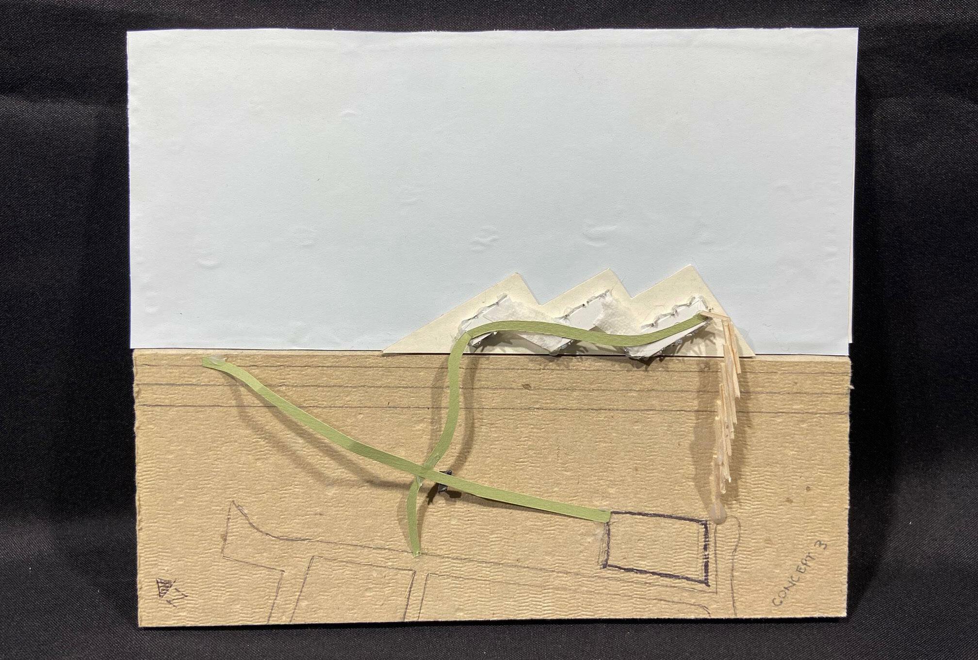
111 CONCEPT MODEL 3
SITE PLAN BUILDING
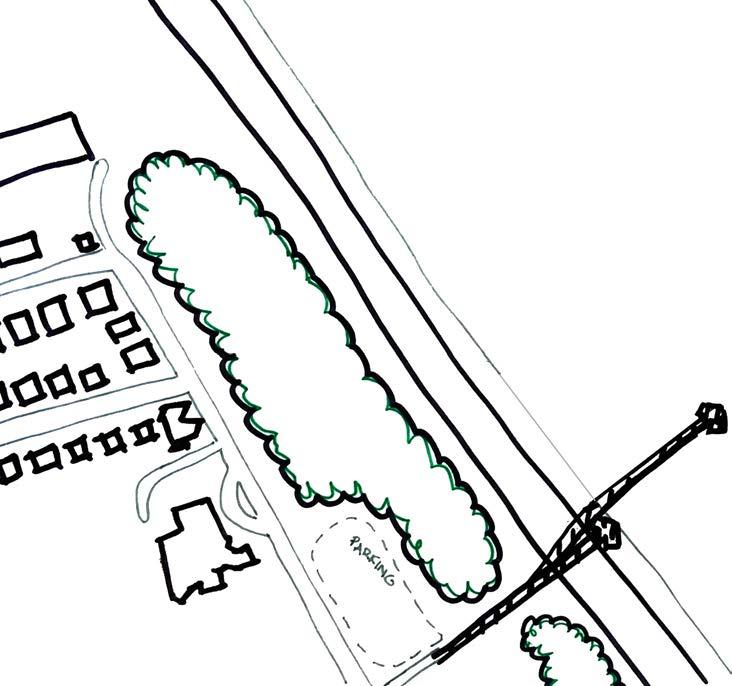
LIBRARY
PEDESTRIAN WALKWAY
CROSS ISLAND HIGHWAY
LATTICING
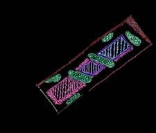
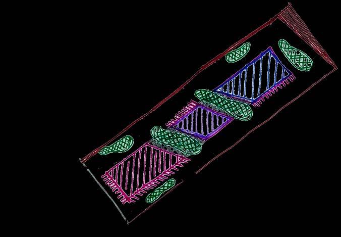
OFFICES/ ROOMS/ MEETING
GREEN SPACES
The program becomes three separate spaces. Office/ room/ meeting first. the cafe. then the library. The idea was to create as many view opportunities for the library. This helps create a different experience for the users. The dock is reaching out into the ocean to allude to expanding and joining communities or sectors or blocks. In between a lattice shade for protection.
112 CONCEPT 4 : THE PLINTH
FORT TOTTEN MILITARY BASE
MARINA FOOTBRIDGE
VIEW POINT DOCK CAFE
STAIRS TO WATER
FORM
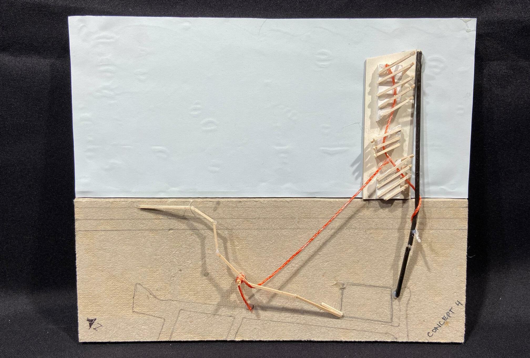
113 CONCEPT MODEL 4
SITE PLAN BUILDING FORM
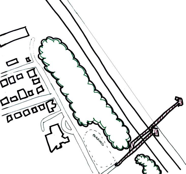
FORT TOTTEN MILITARY BASE
PEDESTRIAN WALKWAY
CROSS ISLAND HIGHWAY
MARINA FOOTBRIDGE
GREEN SPACES
LATTICING
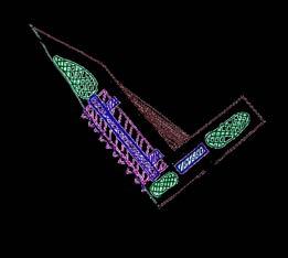

LIBRARY/OFFICES/ ROOMS/ MEETING
STAIRS TO WATER
GREEN SPACES
The program separates into two buildings. One being the cafe reaching out into the waterfront absorbing many views. The other building is a combination of two bars one being the many hub of circulation and program and the other bar sitting in the middle creating event space/ green spaces to soften the interior divisions. as well as using this latticing effect.
114 CONCEPT 5 : THE OUTREACH
VIEW POINT
DOCK CAFE
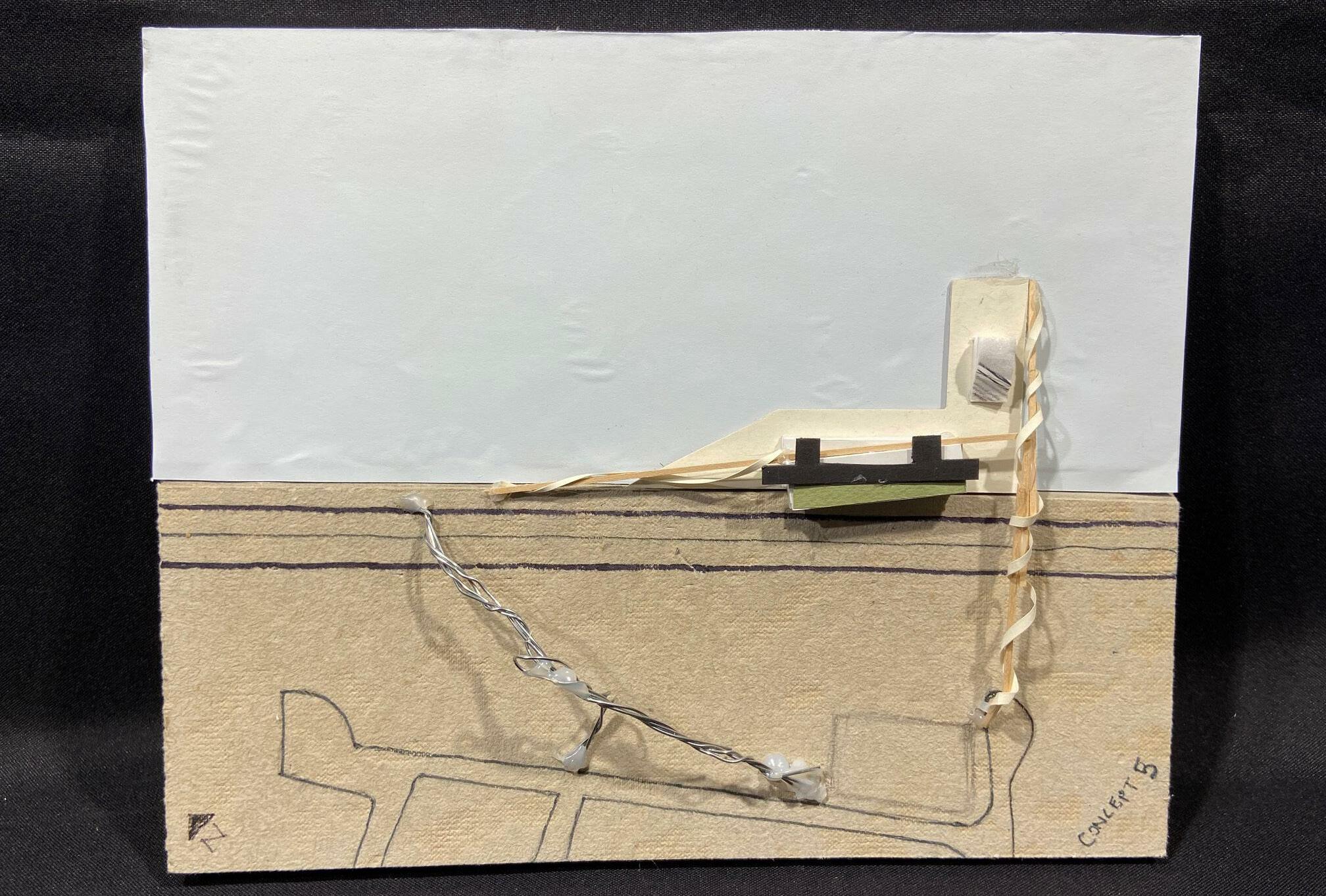
115 CONCEPT MODEL 5
PRELIMINARY REVIEW FEBUARY 11, 2022
BUILDING TYPE
These genres of building types within the communal hub category help obtain goods and services which are helpful and or utilized by any of the near by communities. It is a place where a public space could potentially intrigue neighbourhoods / communities by using a range of programs withing the space (indoor + outdoor). Historical the Greek stoa.
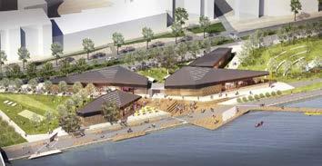
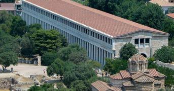
THEORY : CONCEPT
Creating an interactive environment through theoretical connotations of structural expression and ornamentation. This would enable the user to create their own interactive moments from the buildings design.
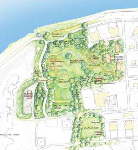
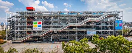
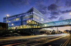
HISTORY
Fort Totten had been in charge of fortifying the eastern part of the bayside area to the new york harbor, then i became non in use because of the civil war and was used as a place for hospitalization and casualty support. After the wars this base housed many.
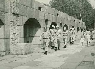
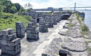
CONNECTION / INTERACTION / COMMUNITY

Interaction is an exchange of information between two people for information or physical acts with people. connection is the ability to bridge one place to another with a matter of a structure or paths. community is a group of people living in the same place or having a particular characteristic in common.


CONCLUSION
Social interaction, communal engagement, connection between different points of arrival and building facades . The communal hub will be a building that would entice people to share time with one another. The ability to create a location where people want to play, socialize, rest, ride their bikes, run etc. Communal connection is a point to where a successful building becomes important, becomes a place where the building symbolizes a place of education, ceremonial and adventure.
118
INTENT
GREEK STOA CONNECTION TO RHODES THE CENTER POMPIDOU
MALL OF JOHN LEWIS
FORT- TOTTEN
A community hub, also referred to as a community center. A building or structure which provides a multiuser of activities. Such that like medical centers, multipurpose center, community centers or a school. These genres of building types within the communal hub category help obtain goods and services which are helpful and or utilized by any of the near by communities. It is a place where a public space could potentially intrigue neighborhoods / communities by using a range of programs withing the space (indoor + outdoor). It is to emphasize better public accessibly, interaction and gatherings under a roof of a structure. They are led by people that are involved with running the programs and services within the building. They are carried out by people volunteering or they could be used by a public agency such as an authority that has a big input towards the community. Its the effort to create a building that hones sustainability factors which help the environment and educate the public about clean energy. The gathering of people for social connection and interaction through the use of public activities. This building type tends to be very multipurpose with being able to be multiple different programs. In history one of the communal hubs would be a example of the Greek stoa. In ancient Greek cities, it was an open space that was utilized as a meeting ground for various activities for the people of the community. First found by the work of Homer. It became their daily religious, political, judicial, social, and commercial activity.
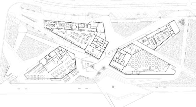
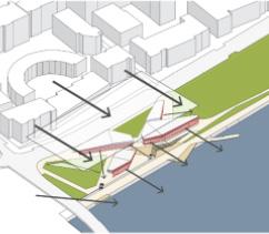
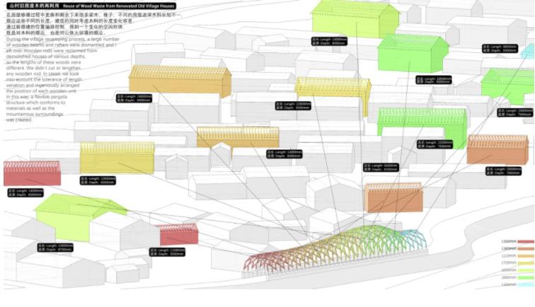
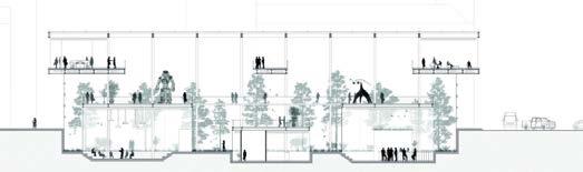
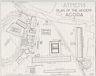

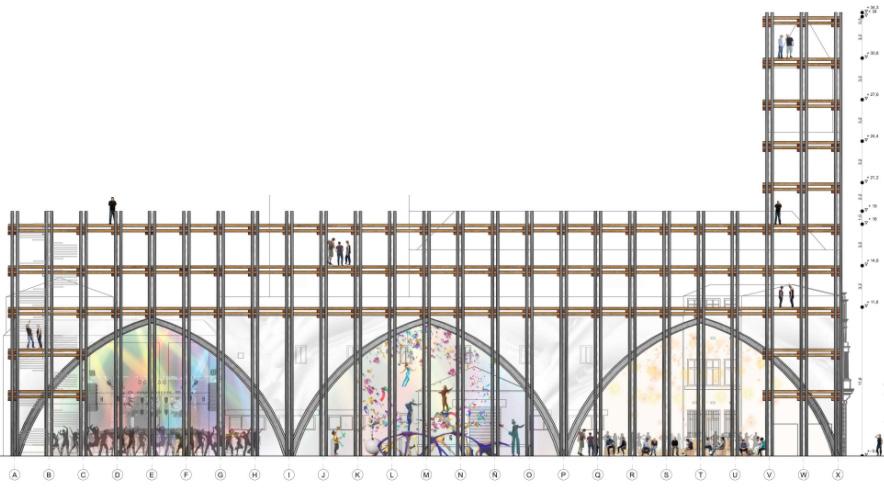
119
COMMUNITY HUB ?
CONNECTION TO RHODES
CONNECTION
TO RHODES PERGOLA LUOTUOWAN
GREEK
STOA
GREEK STOA SITE PLAN
CREATIVE JUNGLE
VERSATILE PAVILION
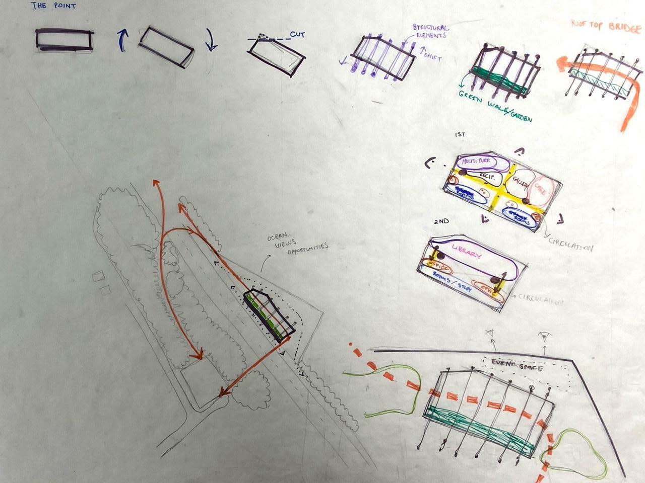
120 CONCEPTUAL DIAGRAM 1
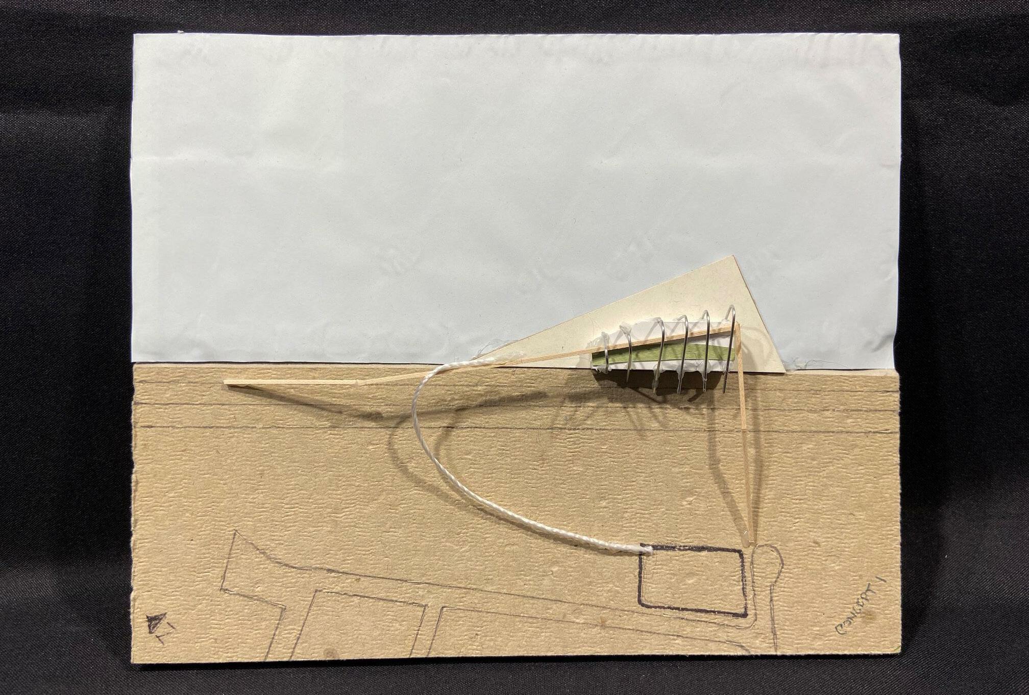
121 CONCEPT MODEL 1
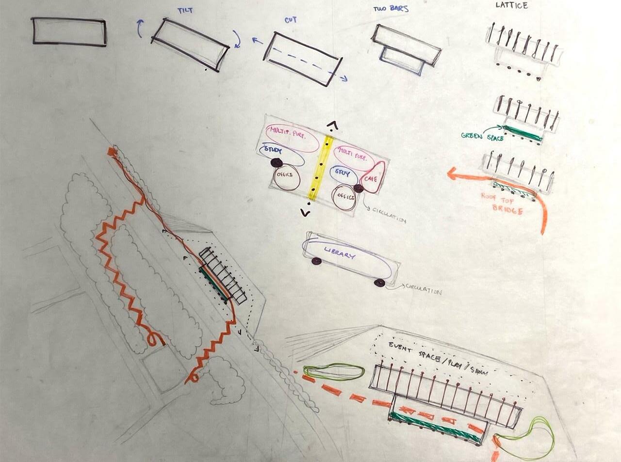
122 CONCEPTUAL DIAGRAM 2
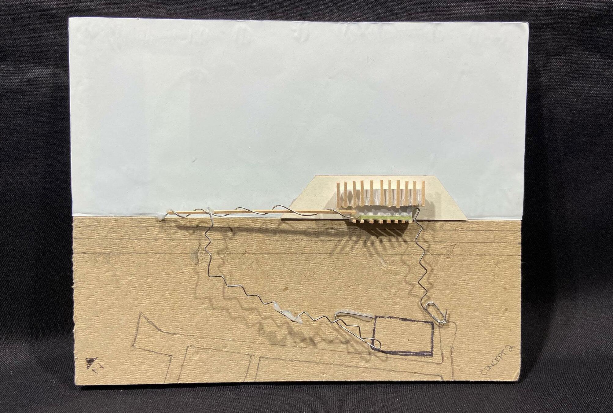
123 CONCEPT MODEL 2
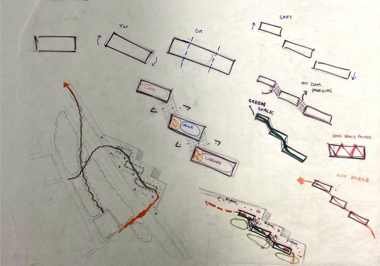
124 CONCEPTUAL DIAGRAM 3

125 CONCEPT MODEL 3
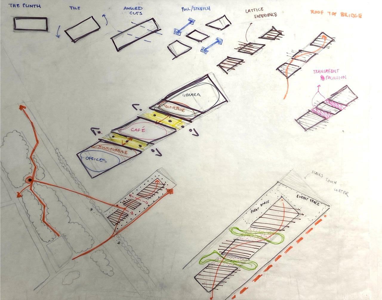
126 CONCEPTUAL DIAGRAM 4

127 CONCEPT MODEL 4
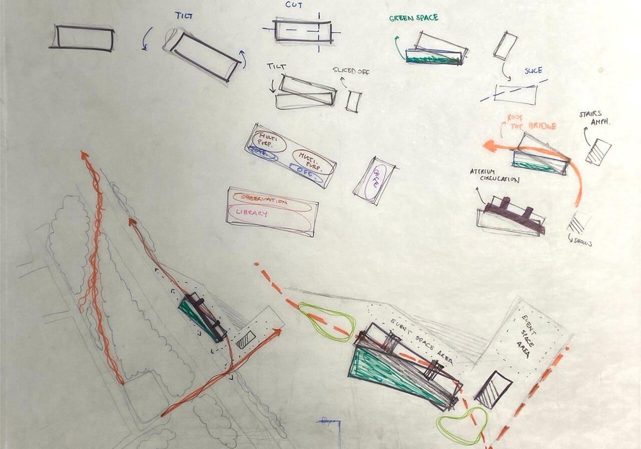
128 CONCEPTUAL DIAGRAM 5
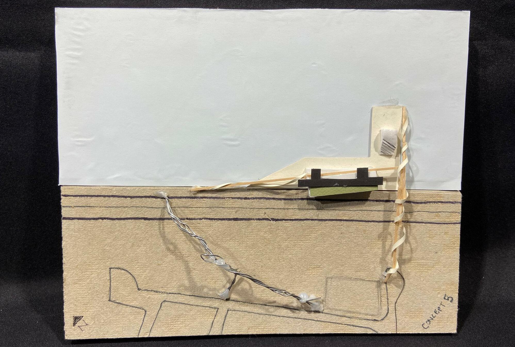
129 CONCEPT MODEL 5
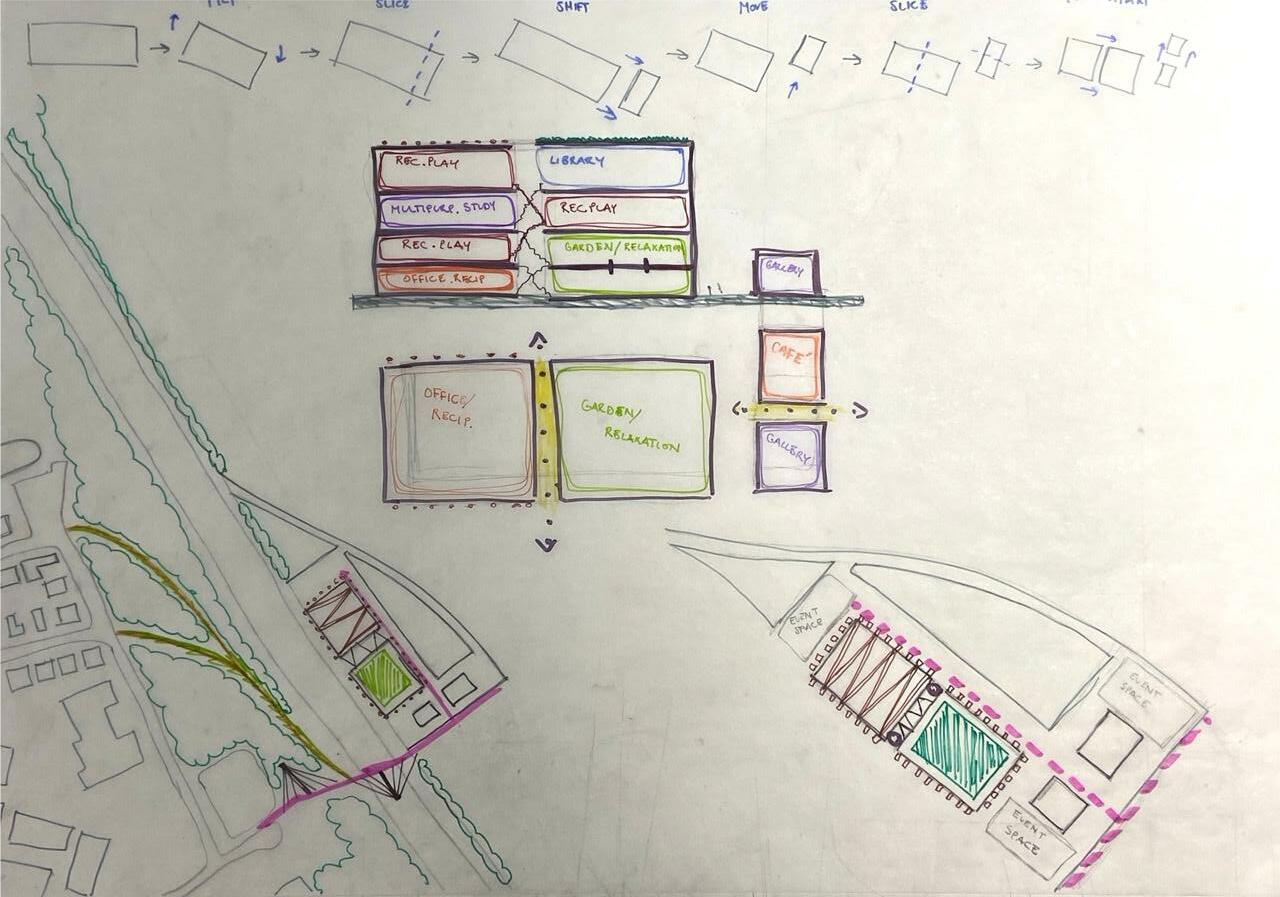
130 CONCEPTUAL DIAGRAM 6
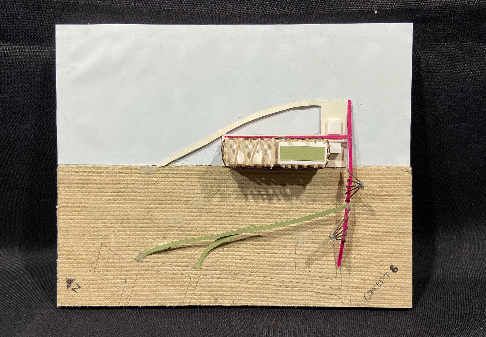
131 CONCEPT MODEL 6
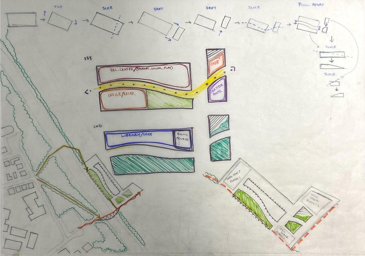
132 CONCEPTUAL DIAGRAM 7
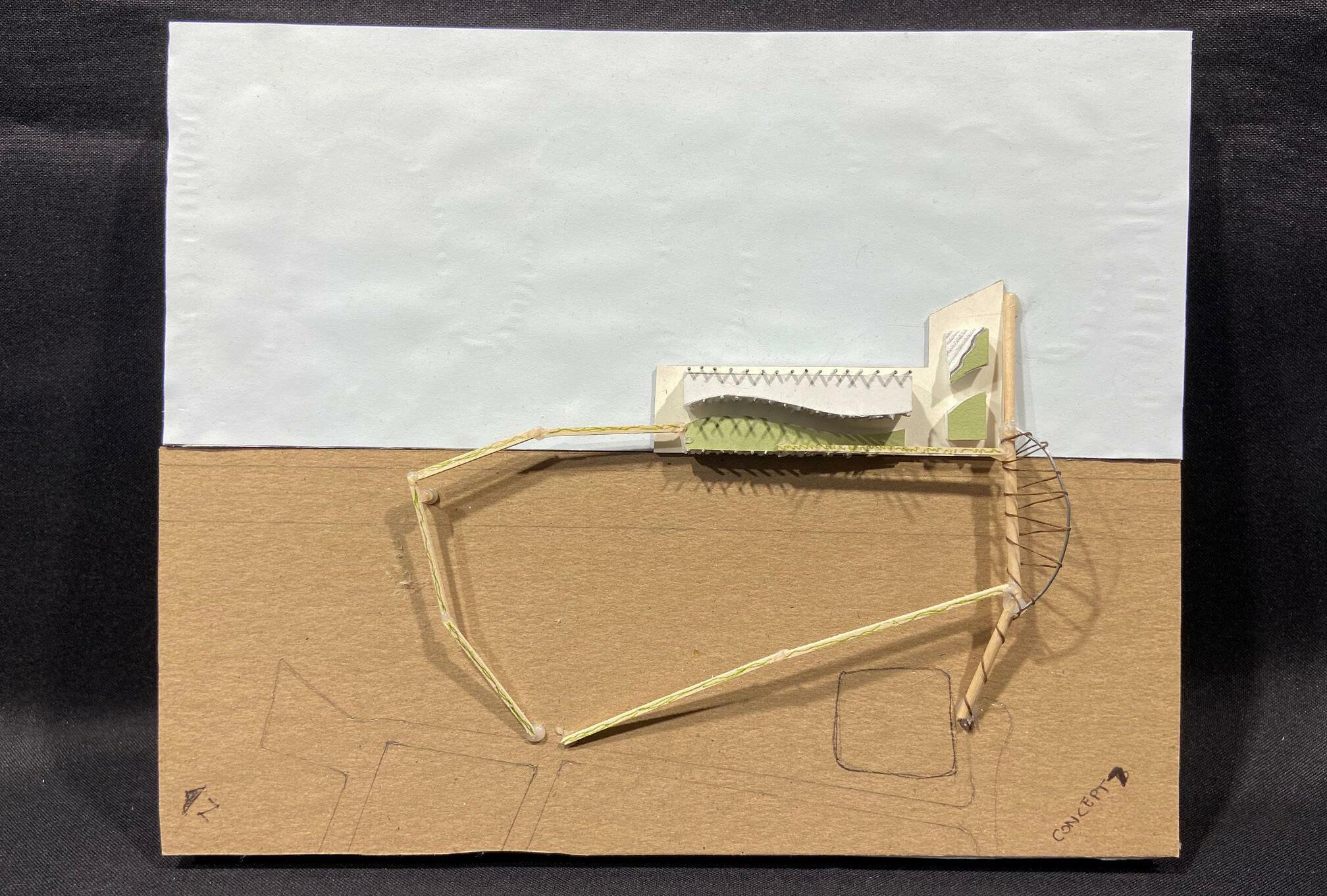
133 CONCEPT MODEL 7
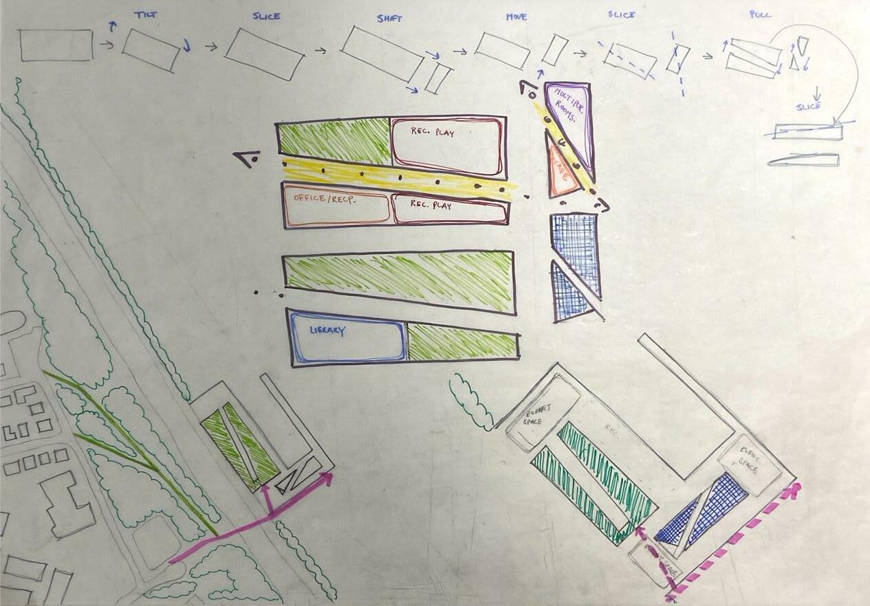
134 CONCEPTUAL DIAGRAM 8
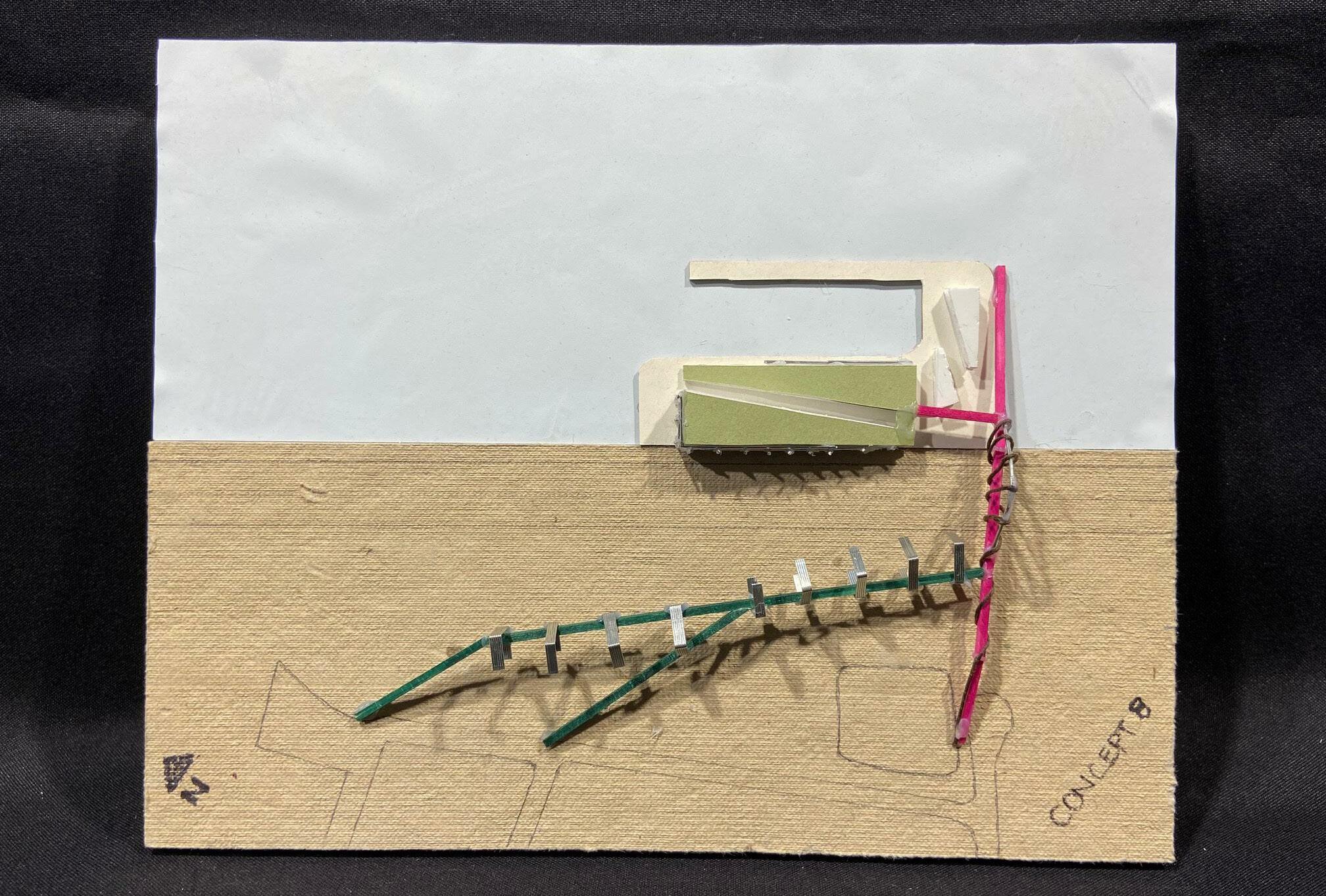
135 CONCEPT MODEL 8
SLICETILT PULL SHIFT
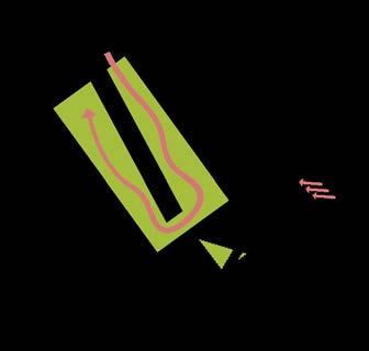
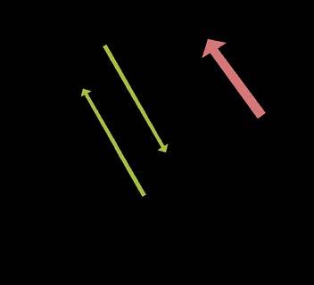


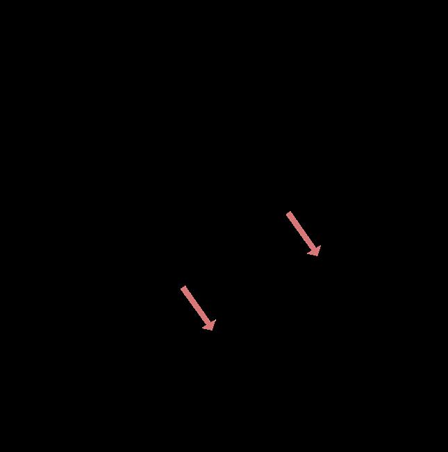

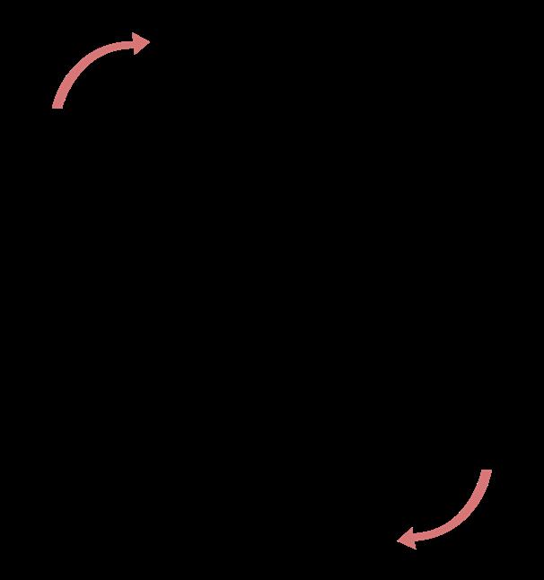
136 CONCEPTUAL PLAN DIAGRAMS
PULLDIVIDE PLINTH + SLOPED ROOF GREEN ROOF + STAIRS
SUBTRACT SHIFT
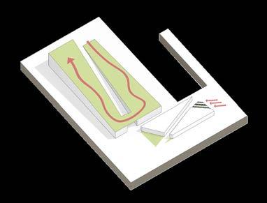
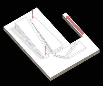
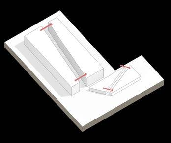
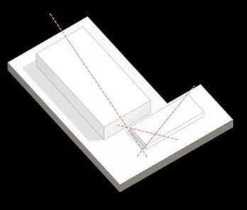
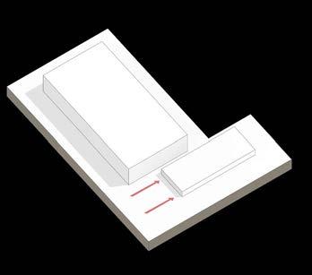
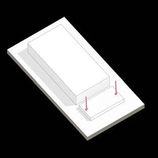
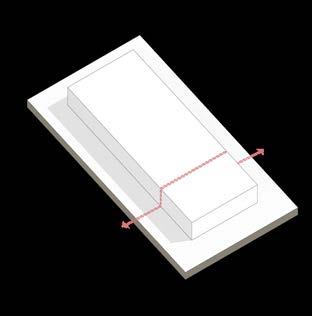
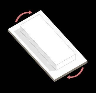
137 CONCEPTUAL AXON DIAGRAMS SLICETILT
PULLDIVIDE PLINTH + SLOPED ROOF GREEN ROOF + STAIRS
Creating a form where the land start to become structure while ramping up over the highway.
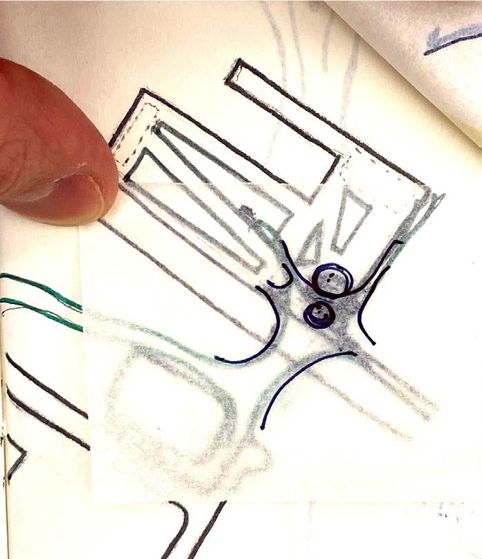
The land bridge starts to take a bigger form over the highway. Also is wants to start touching the building next to it.
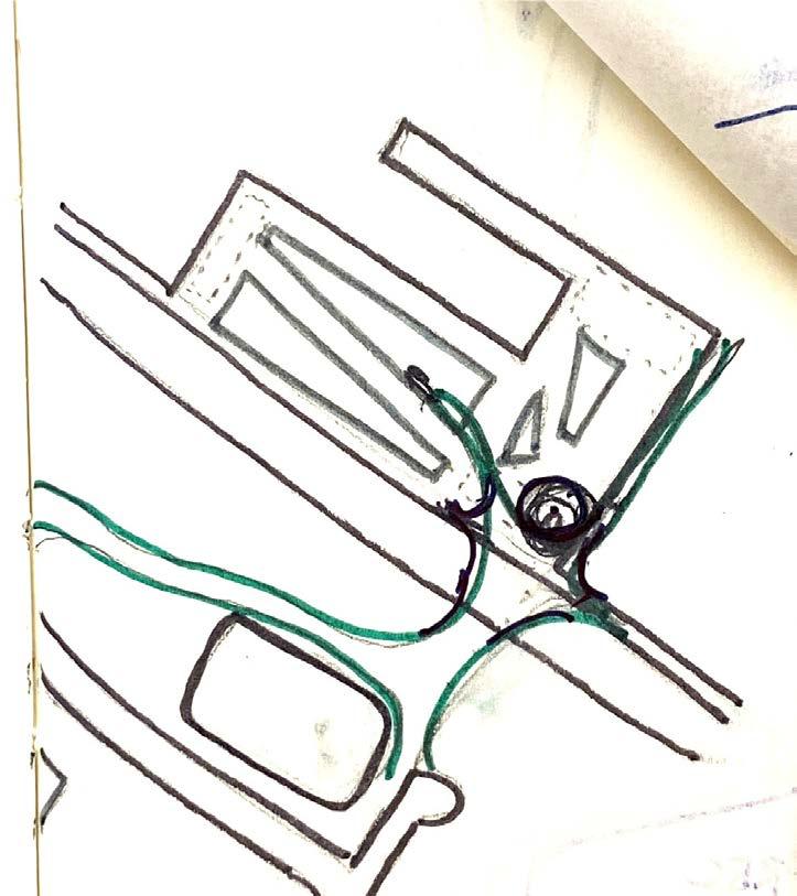
138 FOOT BRIDGE FORM DIAGRAMS
The bridge starts to take account for the node. With that node the bridge also is influenced by its shape by splitting into a system of roots for site and building interaction.
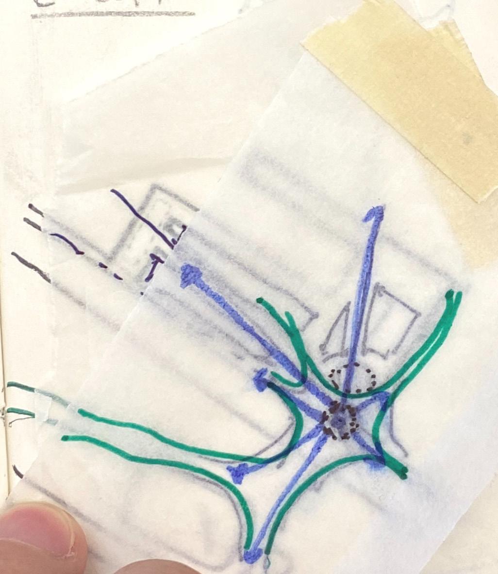
The bridge is now becoming part of the site and building. It helps open the bottom of the site with emphasizing its paths in between the buildings footprint. Also its ability to become part of the building creates a whole new experience for the community.
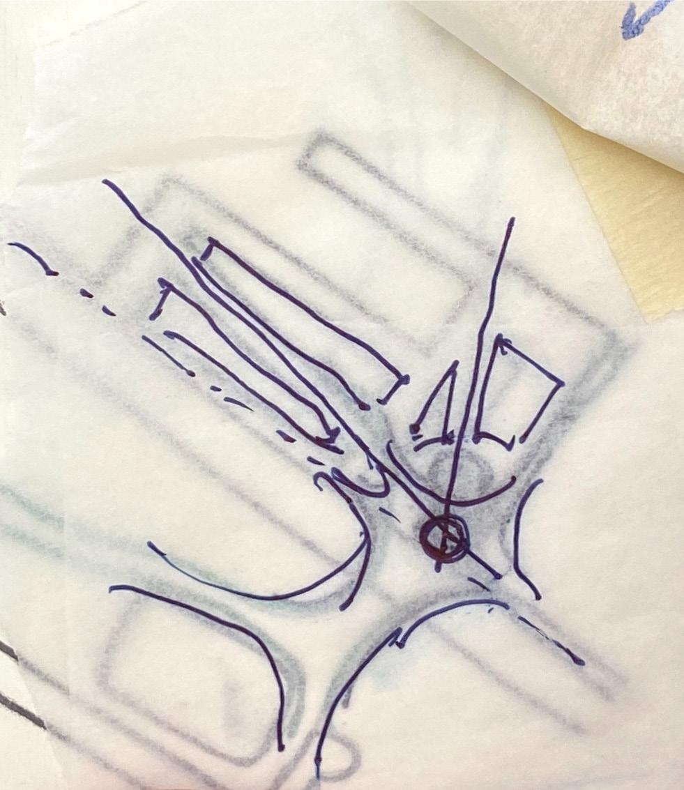
139
PATH ANALYSIS

The three dashed paths represent the primary and secondary roads that lead to the site. The dash red is the primary and the dashed brown are the secondary roads.
TILT PATHS
The dash line then converge with one another creating a connection from secondary roads to primary roads. These paths would lead users on the footbridge guiding them over the highway.

CONNECT PATHS
The path reaches over the highway onto the building footprint. Interjecting line sprout out into the site creating entrances and exits to circulate from the pedestrian bridge.
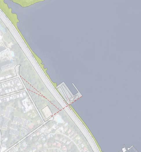
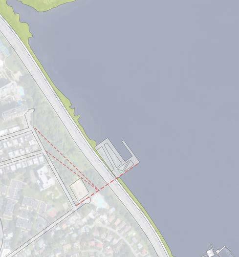
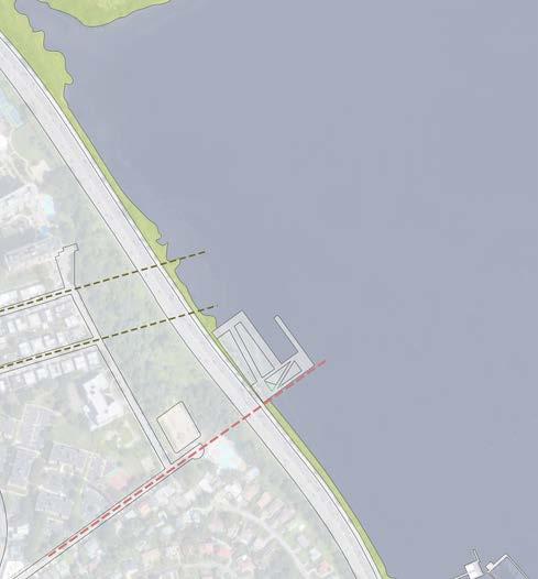
140 FOOT BRIDGE PROCESS DIAGRAMS
OVERLAP BRIDGE
From the dashed lines an overlay of an organic shape. The land bridge starts to take form. Undulating curves and paths.
BUILDING BRIDGE INTEGRATIONTILT PATHS
At the central mark of the bridge a node. This node becomes the land mark element which signifies the site. This node helps the building form by cutting and splitting the program by creating paths in between the site.

With the finalized process the bridge sits at this organic form and shape. It ability to sprawl from the residential side to the waterfront makes is a great experience for travel.

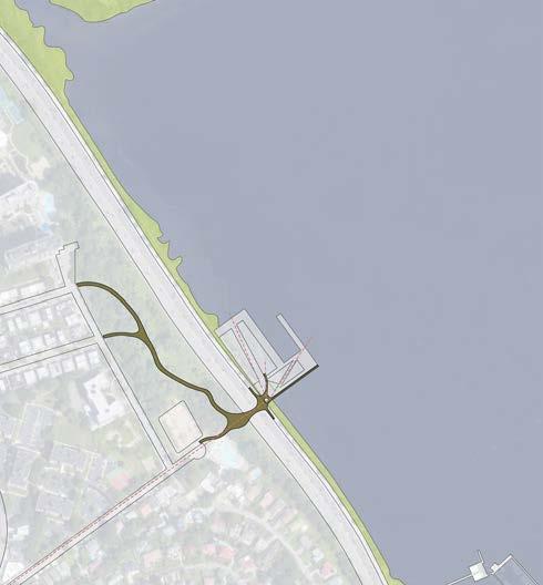
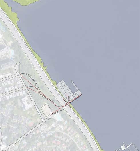
141
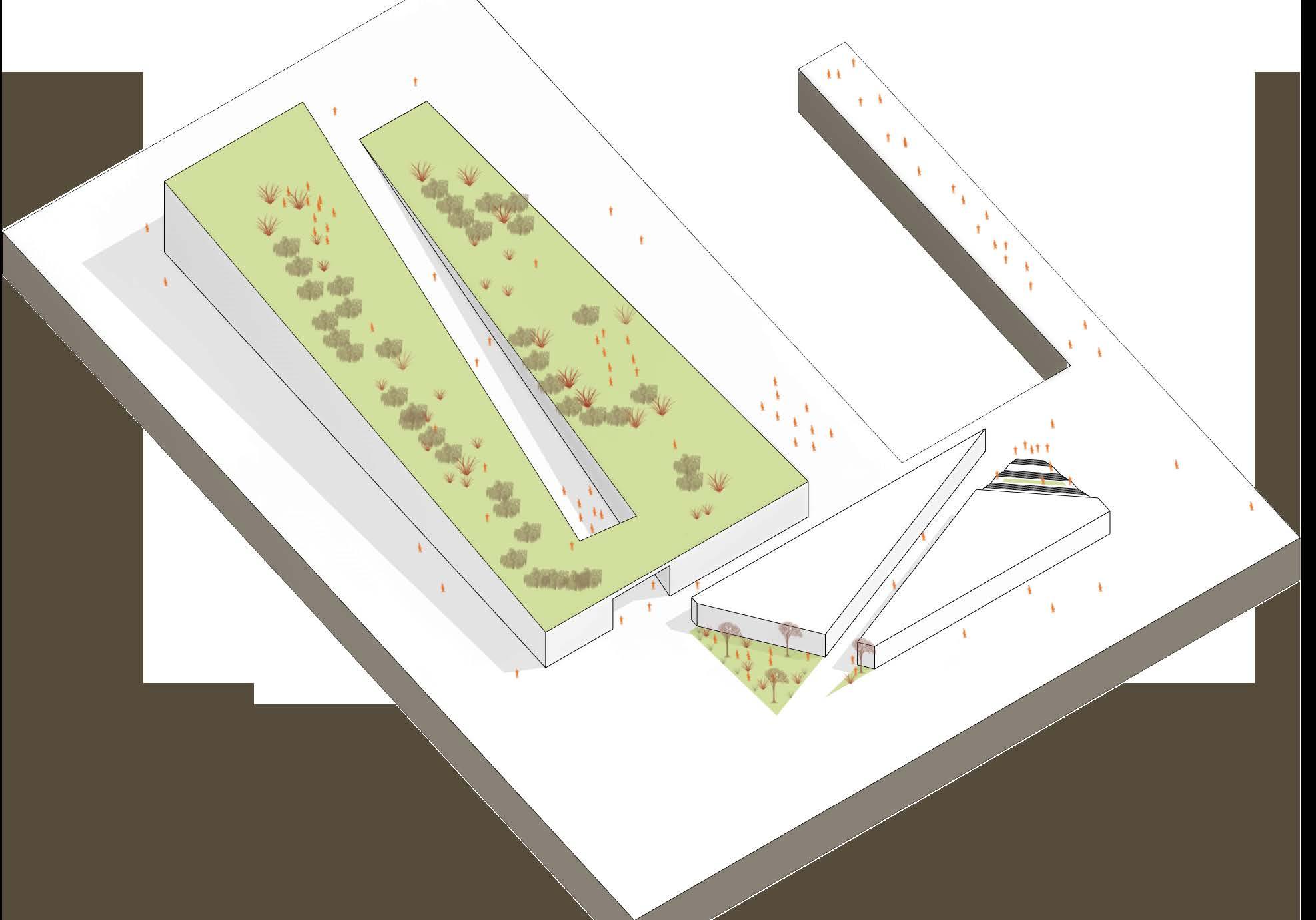
142 BUILDING MASS
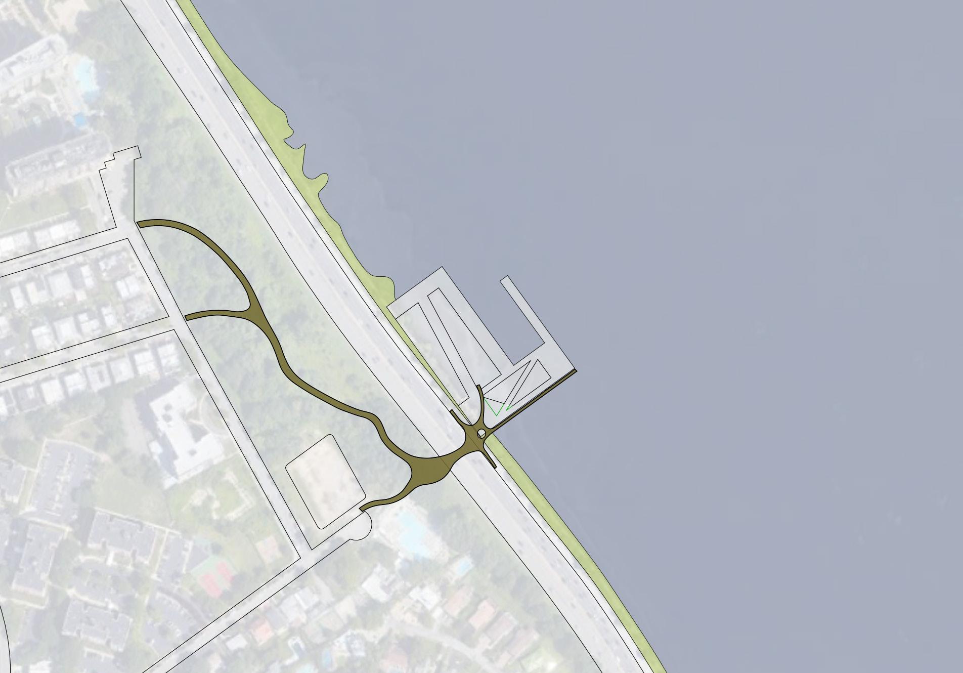

143 LAND BRIDGE FORM
OFFICES
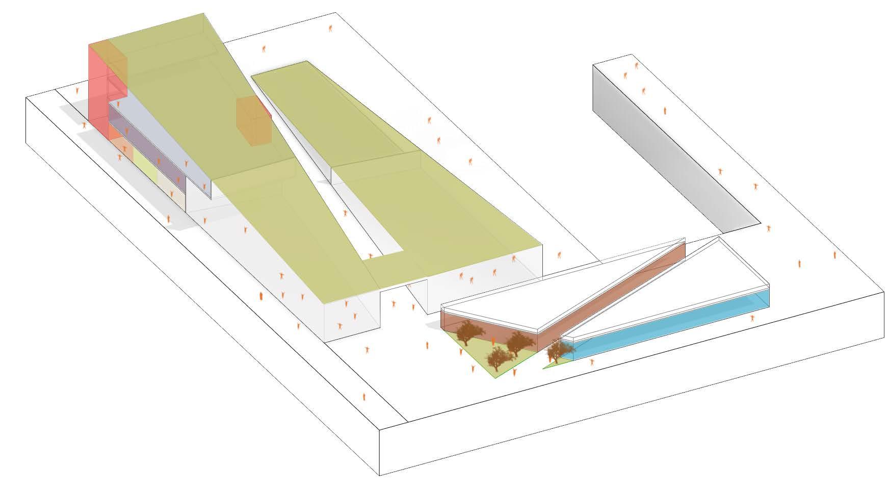
MULTIPURPOSE
RECEPTION
144 GALLERY CAFE RECREATION RECREATION LIBRARY
RM.
CORE ENTRANCE CIRCULATION AXON PROGRAM SCHEMATIC
PROGRAM SCHEMATIC
CORE
RM.OFFICES
LIBRARY RECEPTION
ROOF TOP GARDEN
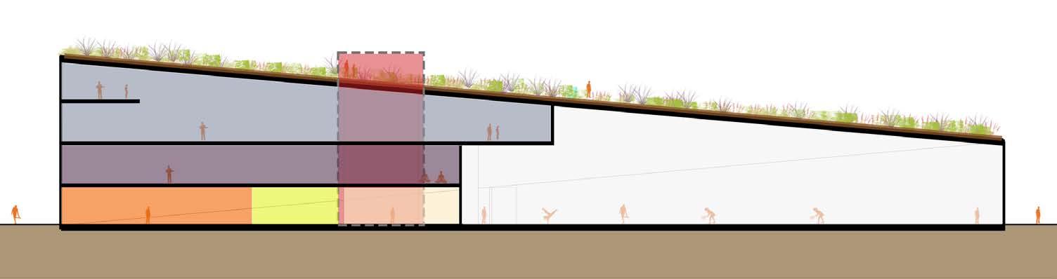
145 RECREATION
MULTIPURPOSE
ENTRANCE CIRCULATION
ENTRANCE CIRCULATION SECTION
MID CRIT. REVIEW MARCH 11, 2022
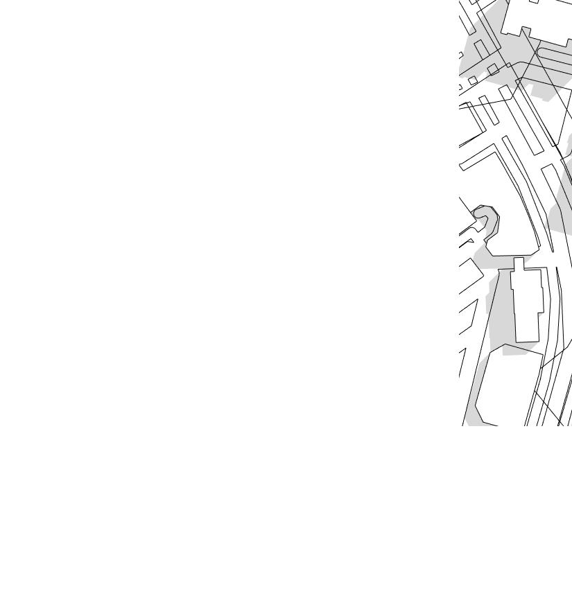
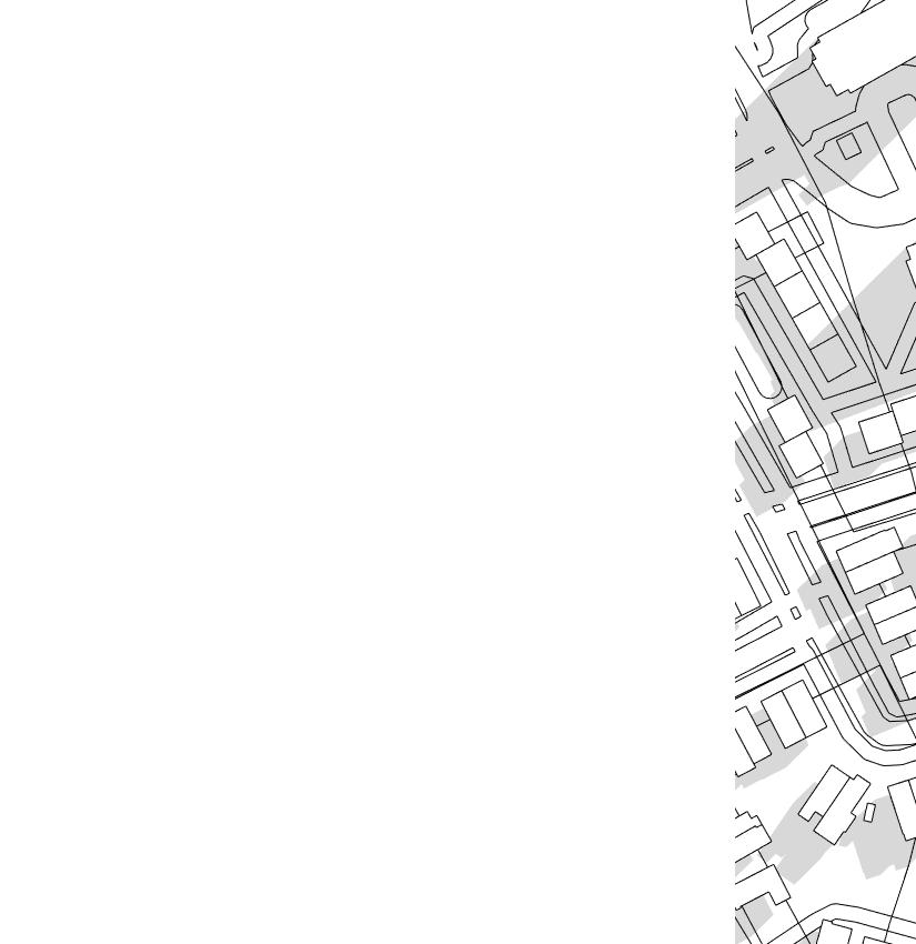
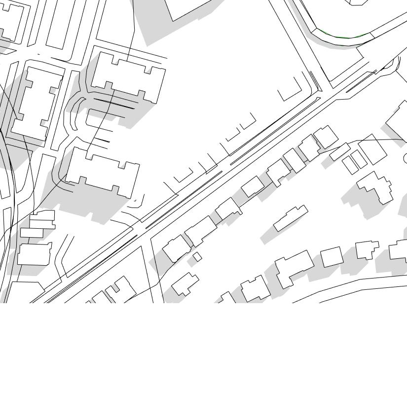
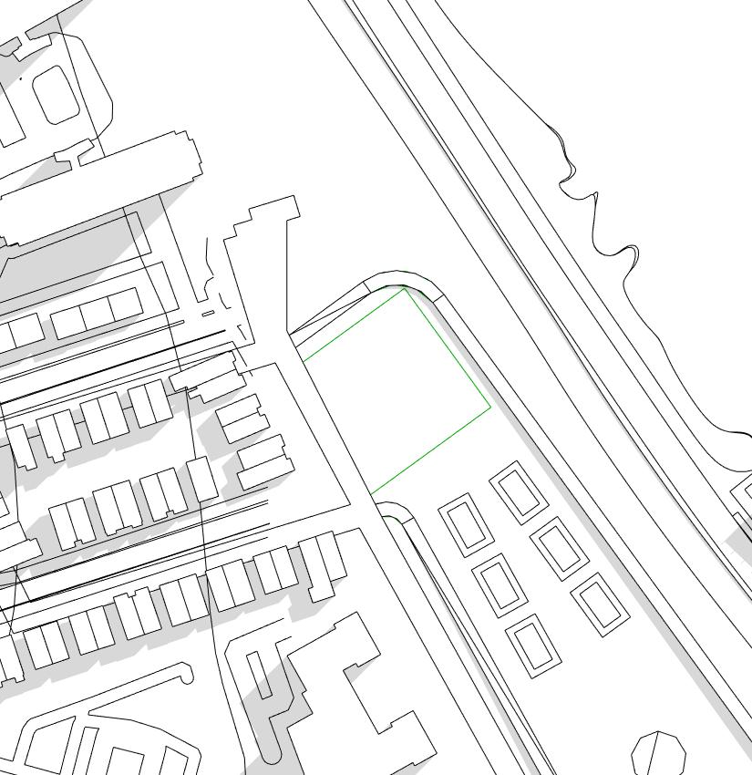
SITE PLAN PARKING BEACH VOLLEYBALL COURTS AMPHITHEATER RAMP RAMP
LANDBRIDGE
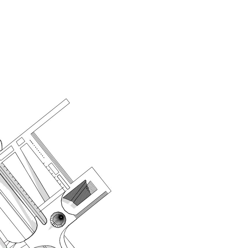
LAWN
PEDESTRIAN WALKWAY
AMPHITHEATER
The site located in little neck, queens, New York. A community hub which sits on the water front hugging the existing pedestrian walkway which hugs a highway ( cross island Parkway). Adjacent to all that opposite from it all is the residential side of the located area. A building which explore the idea of interaction, connection and community. How people interact with the building and the bridge. How the building and bridge cohesively connect together from waterfront to residential side. For the community aspect, what is created to be impactful such elements or landmark to congregate people.
“ To design a building which impacts the site through Interaction, connection and community by exploring ornamentation and structural expression. ”
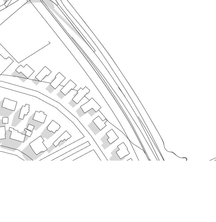
149
GRAND STAIR CASE
PIER OPEN
OPEN LAWN
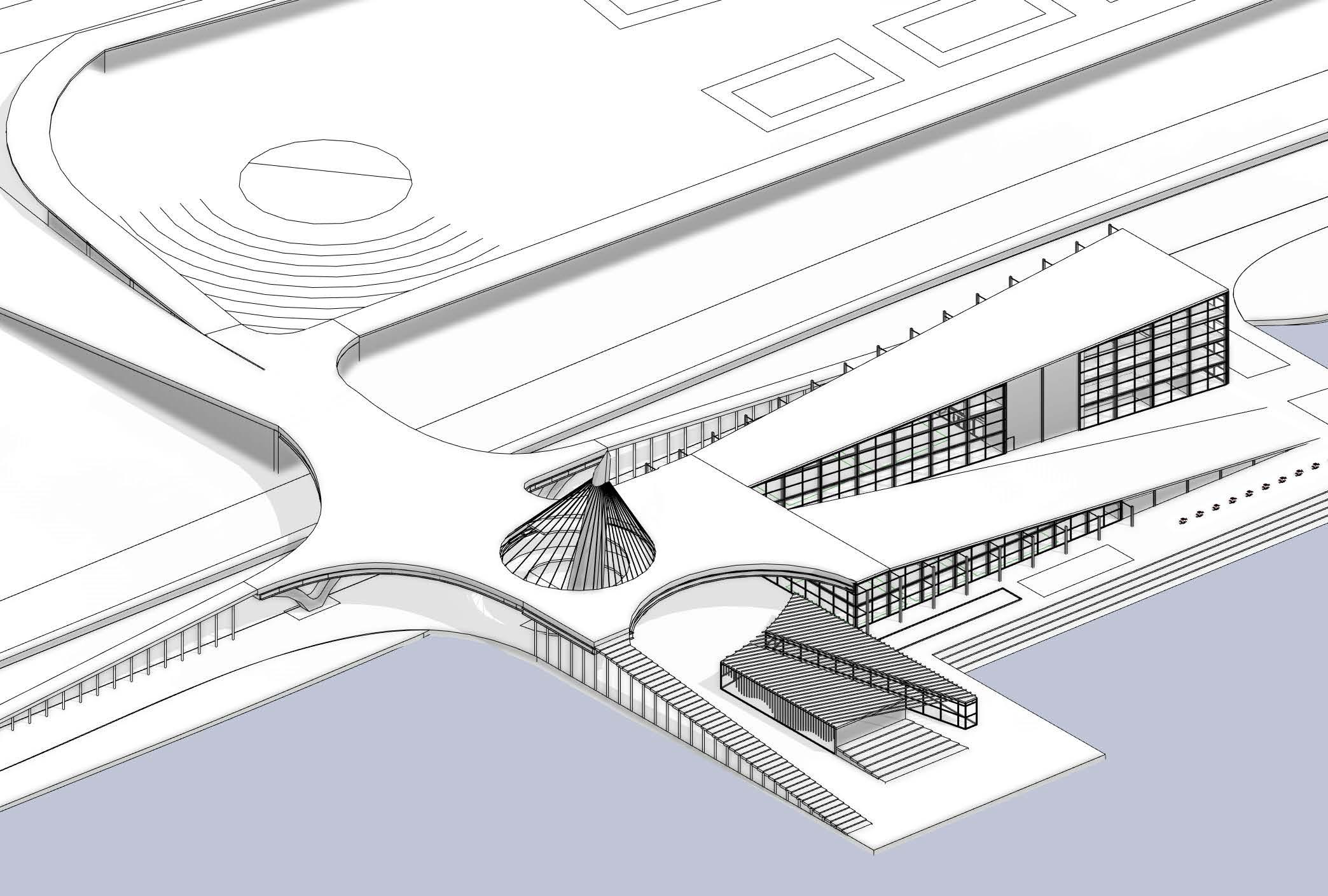
150 BUILDING FORM AXON
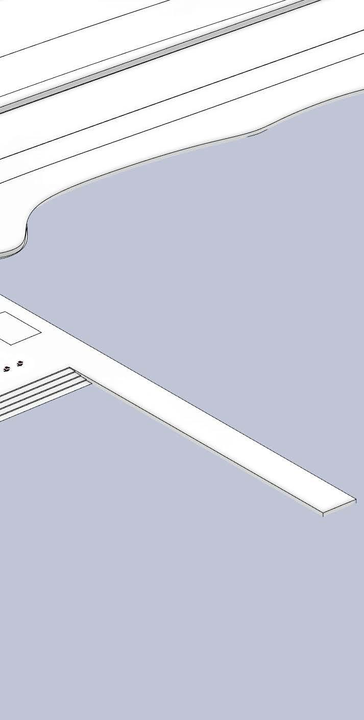

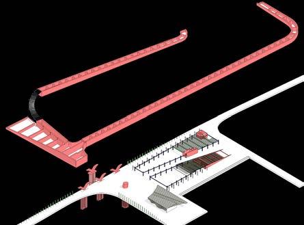
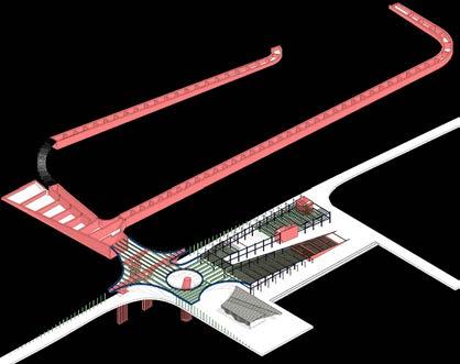
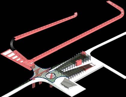

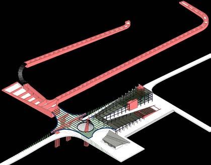
151 CONSTRUCTION PHASE 1 CONSTRUCTION PHASE 2 CONSTRUCTION PHASE 3 CONSTRUCTION PHASE 4 CONSTRUCTION PHASE 5 CONSTRUCTION PHASE 6
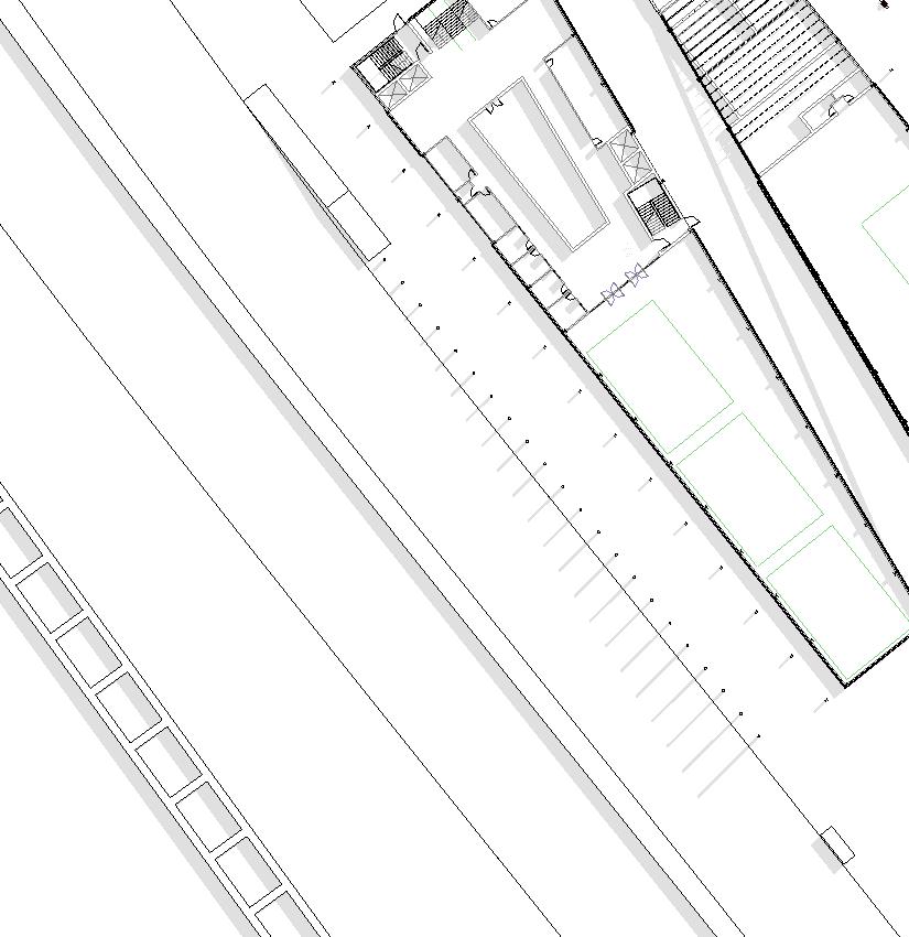
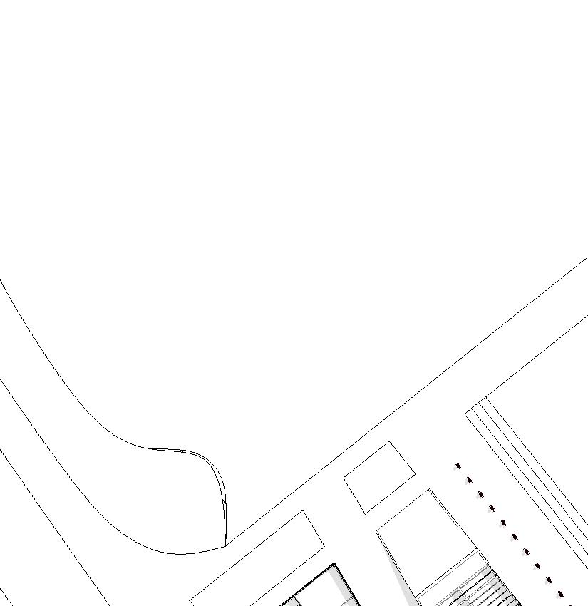
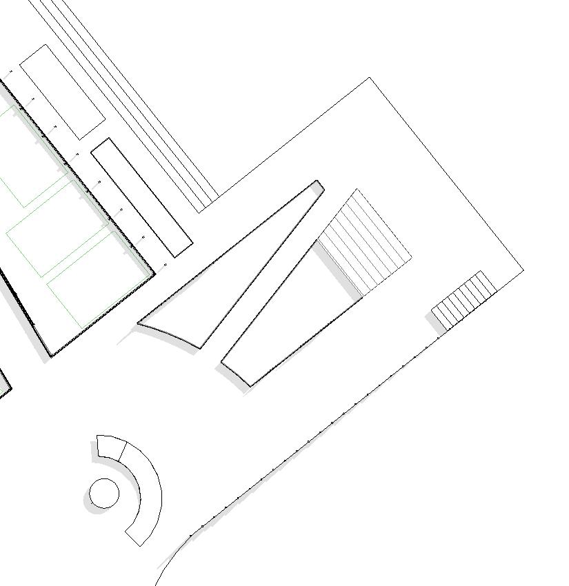


152 FIRST FLOOR REC. 1 REC. 2 MUSEUM CAFE MECH. STORAGE OFFICE BATHROOM
BATHROOM
MULTI. PURPOSE ROOMS

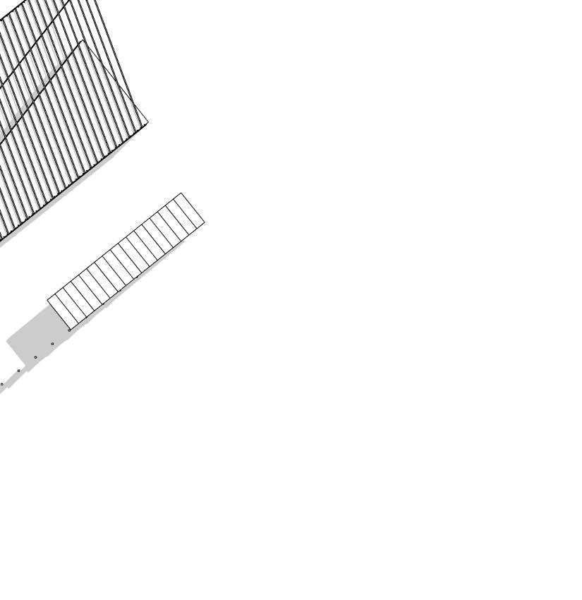
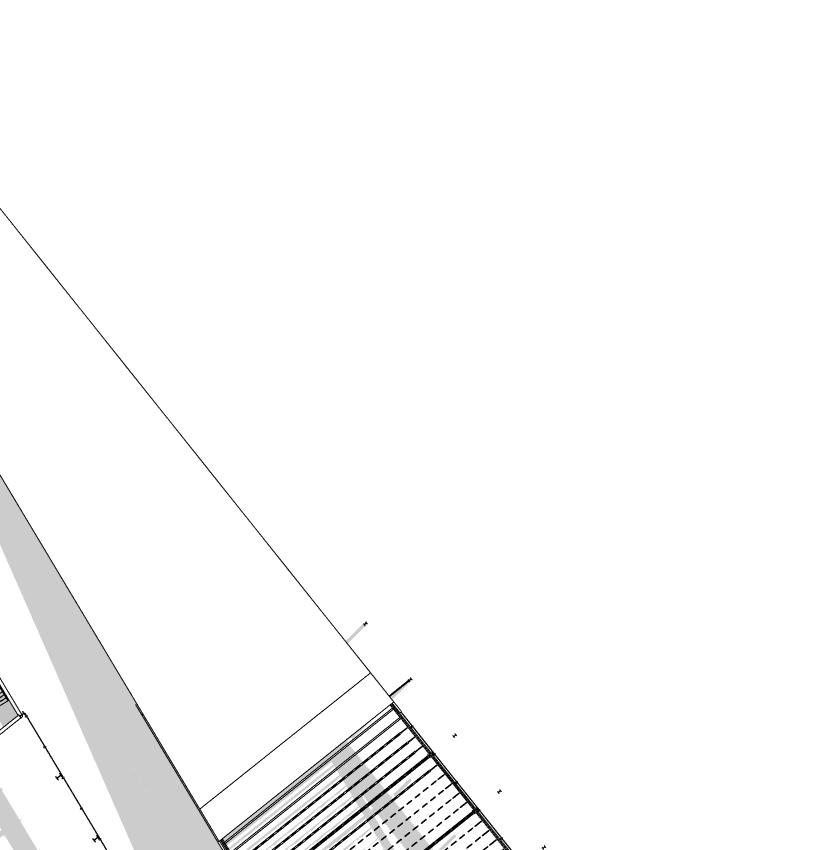
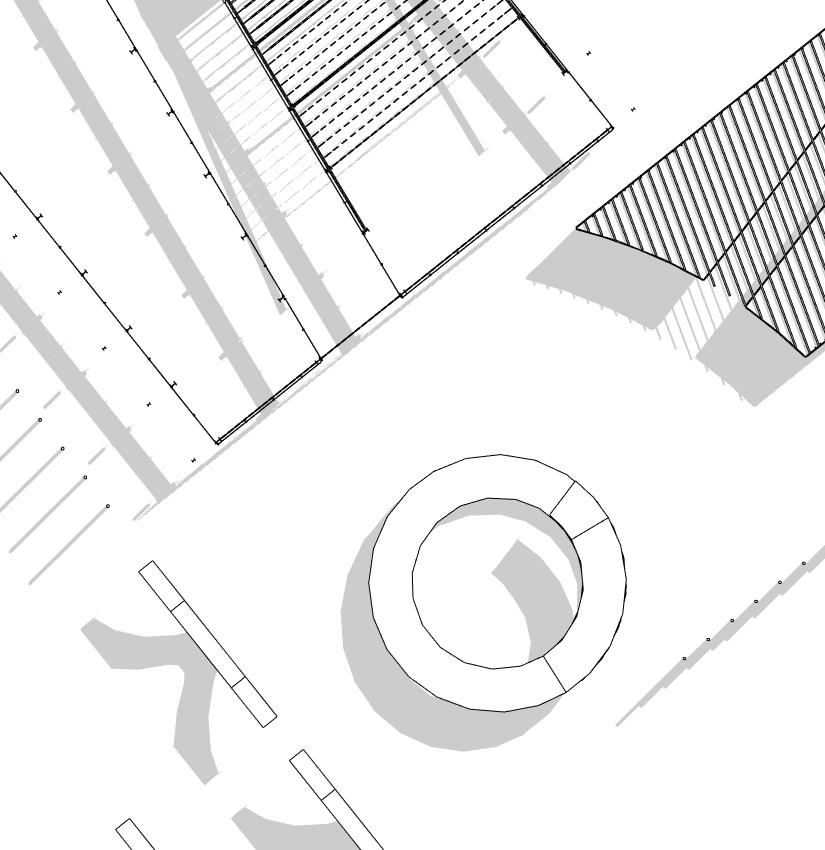
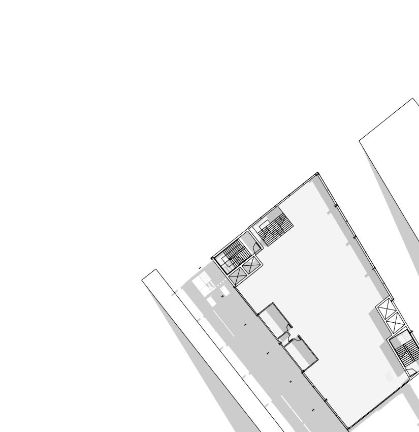
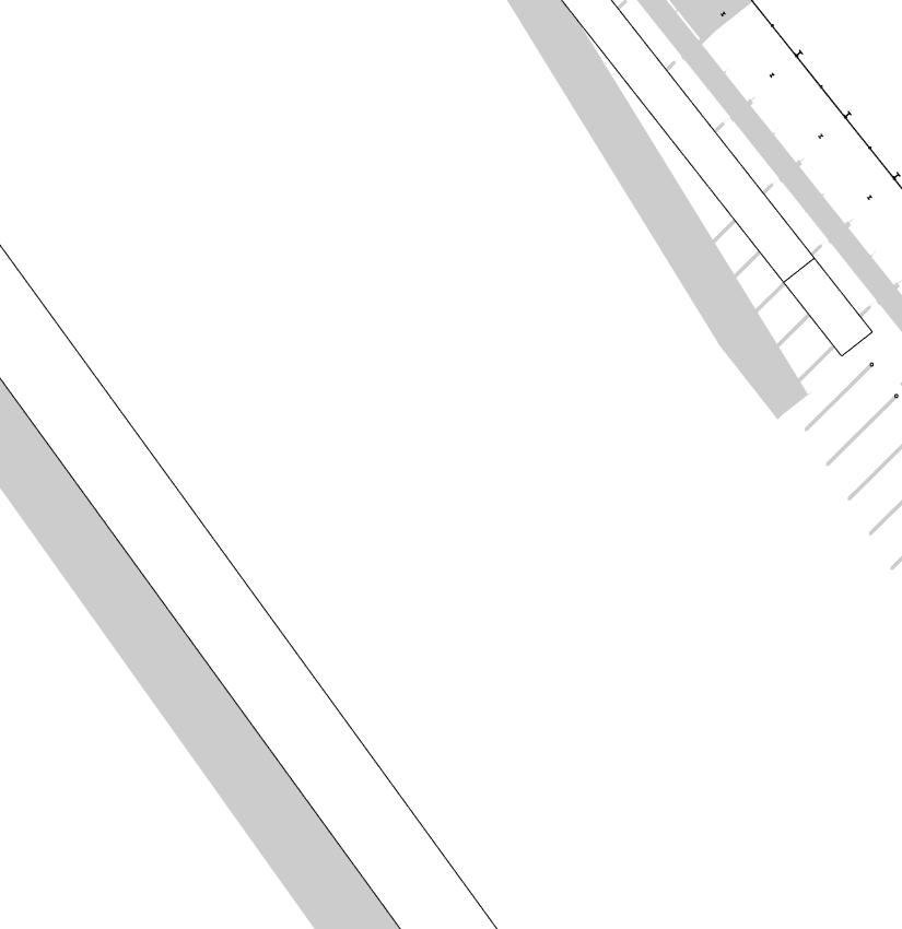
153 SECOND FLOOR
BATHROOM
LIBRARY

154 THIRD FLOOR
PENT HOUSE

155 FOURTH FLOOR
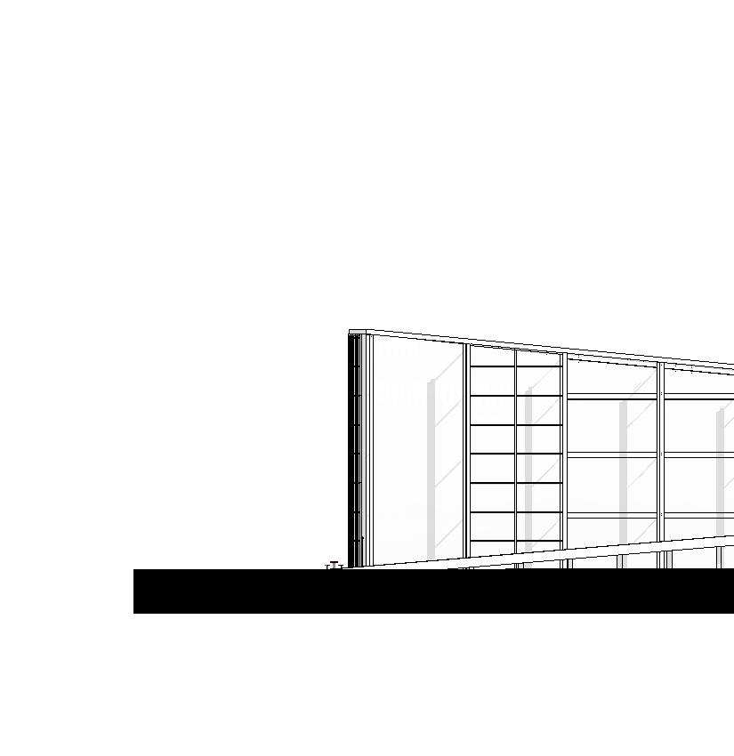
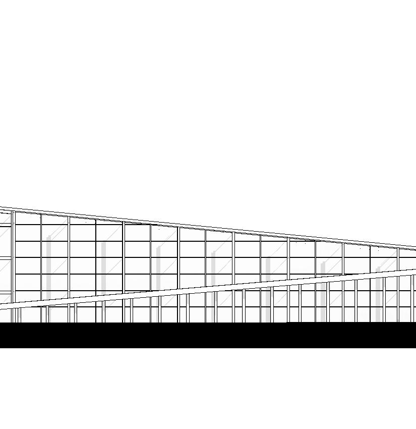
156 WEST ELEVATION
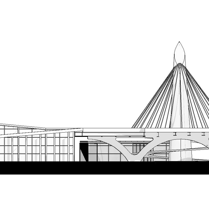
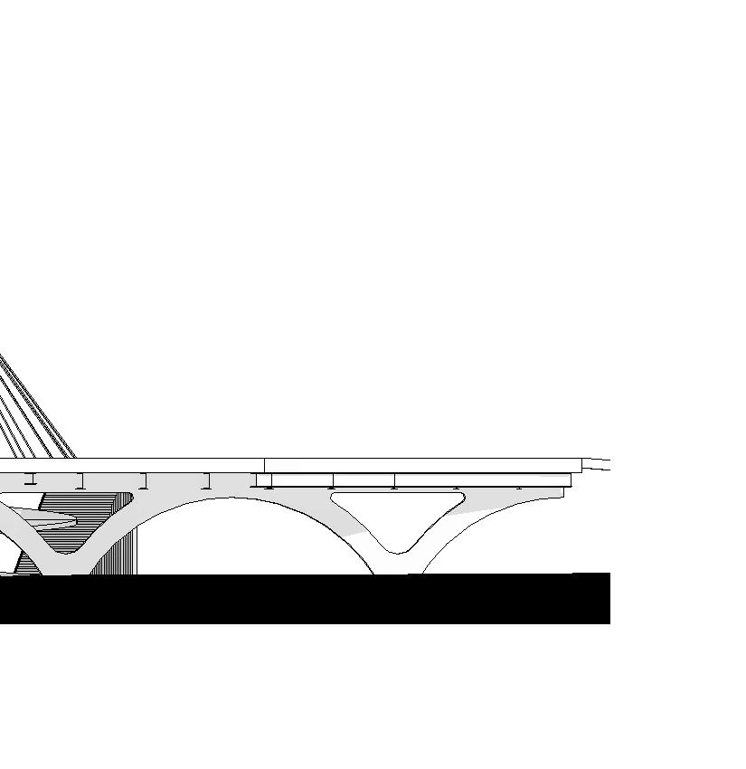
157

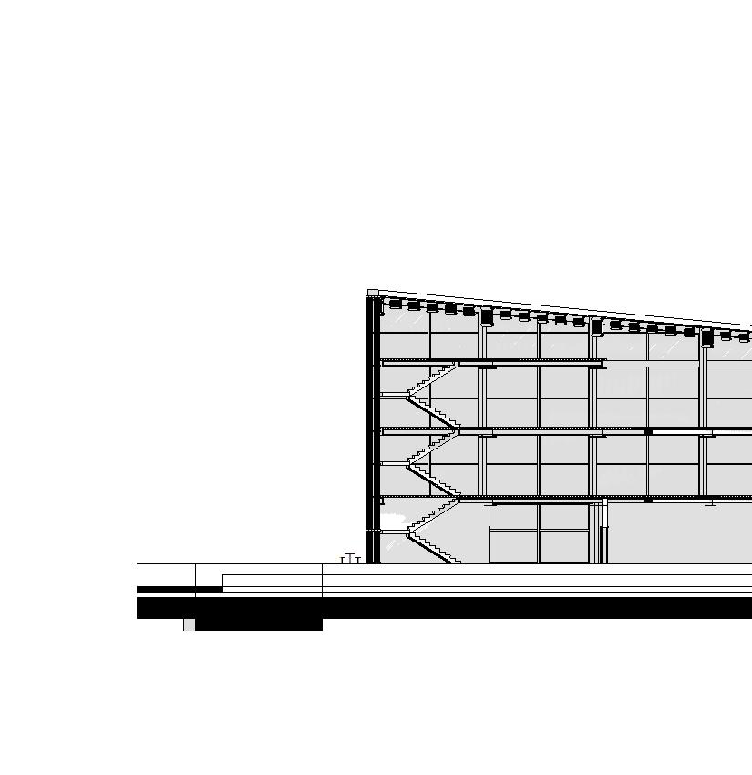
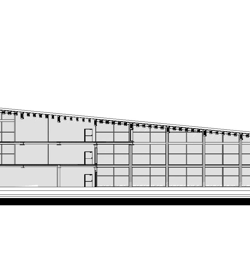
WEST SECTION
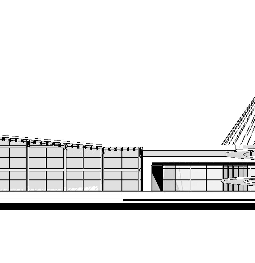
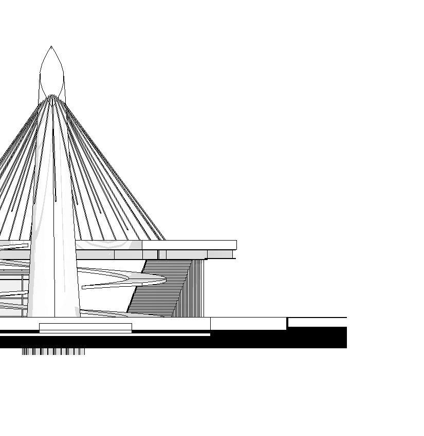
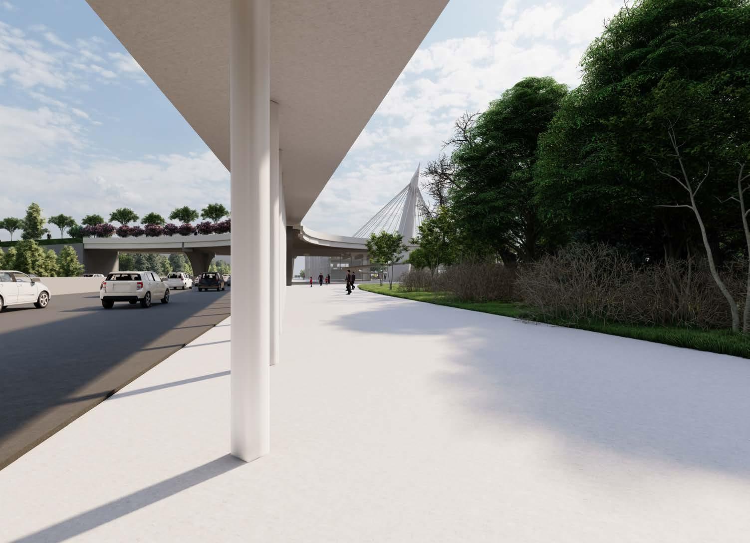
160 EXTERIOR PEDESTRIAN PATH
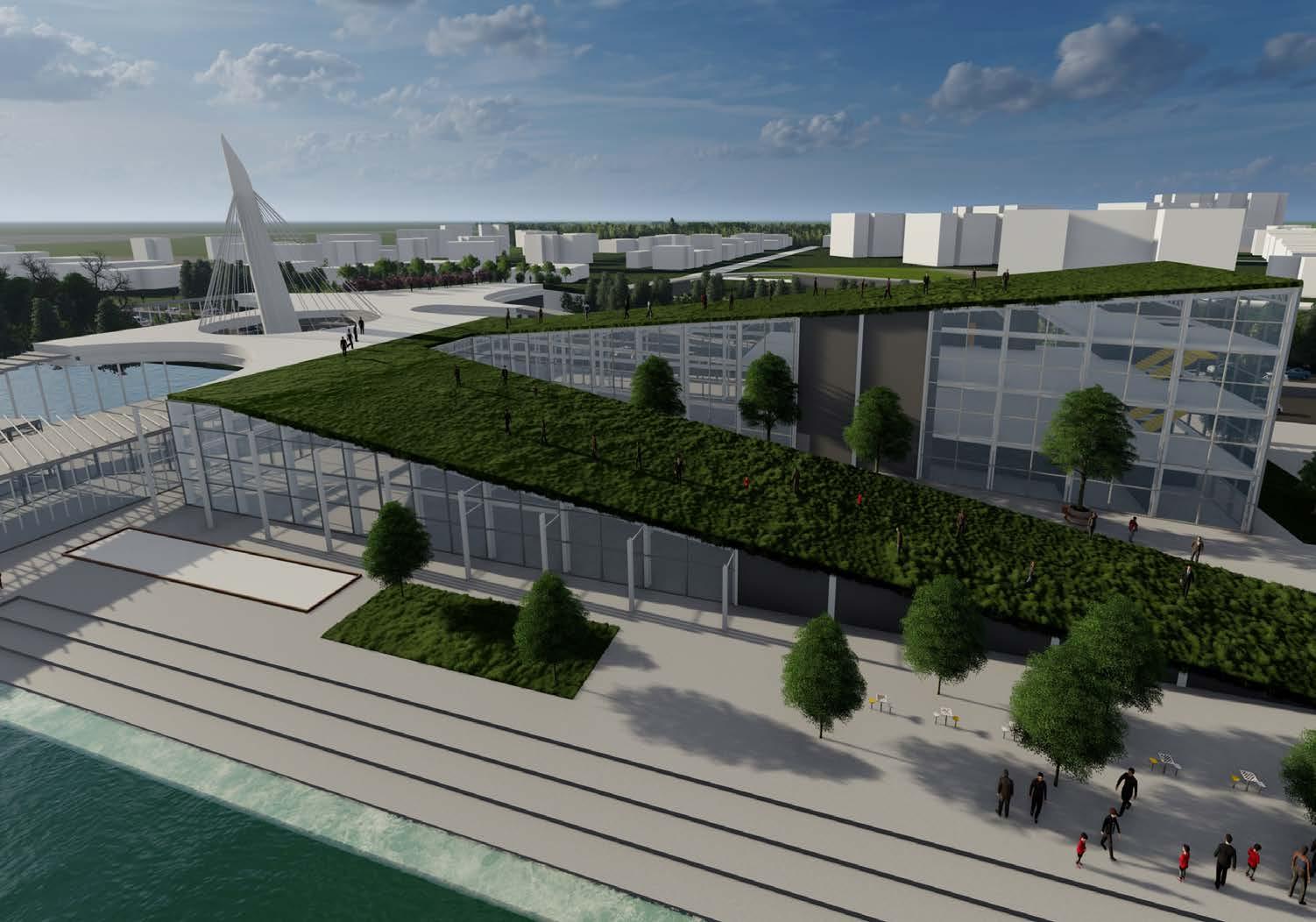
161 ARIEL VIEW OF SLOPING ROOFS
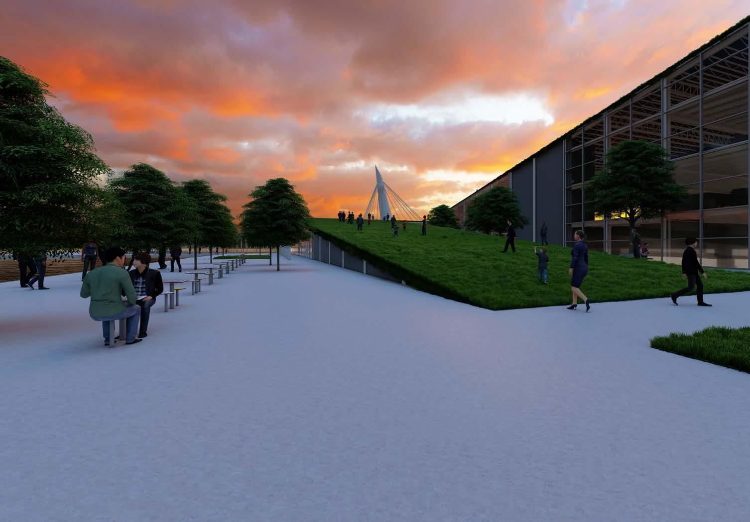
162 SLOPING GREEN ROOF
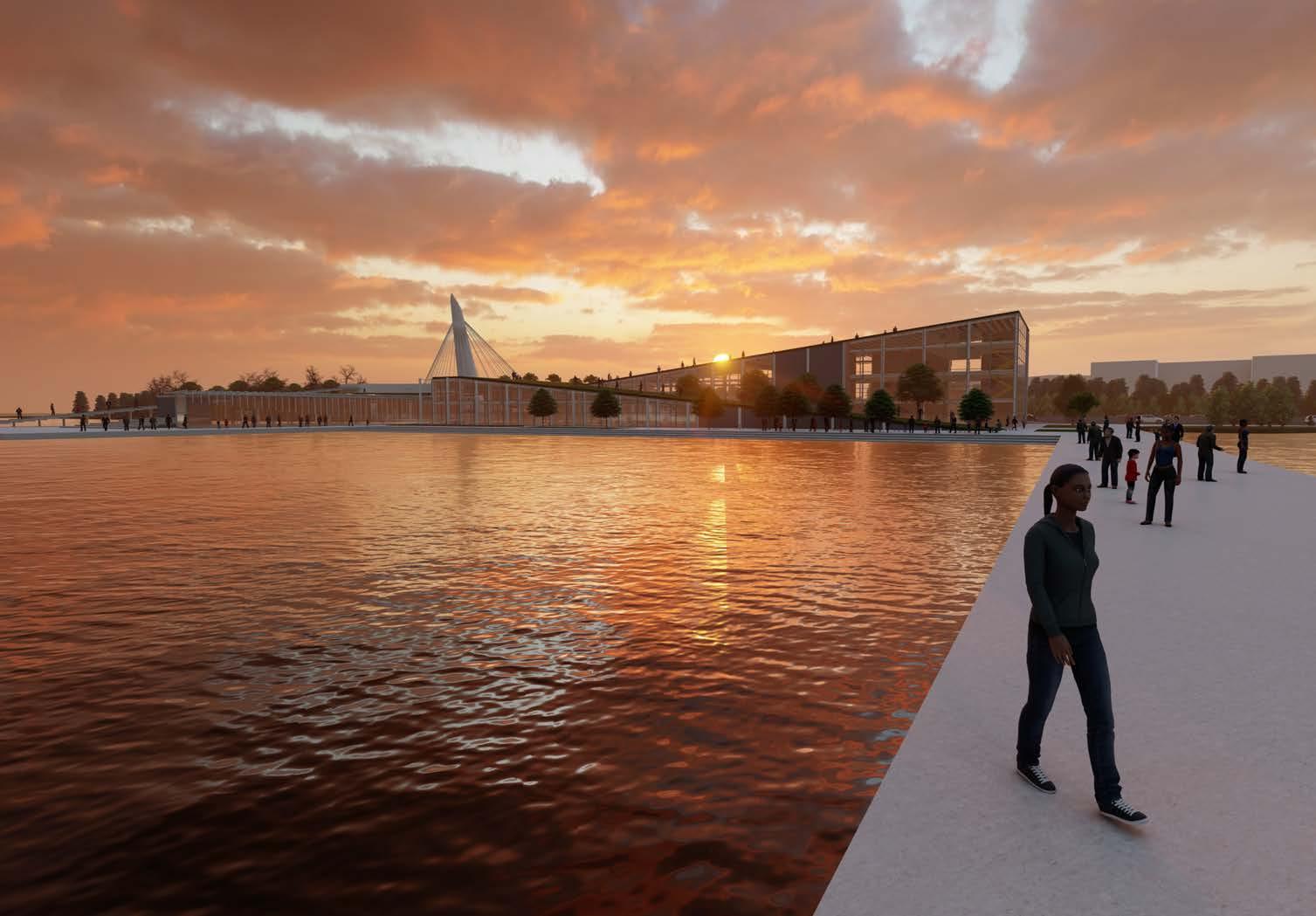
163 EXTERIOR PIER VIEW
PIER 24 : FINAL REVIEW APRIL 22, 2022
PROCESS TRACE DRAWINGS
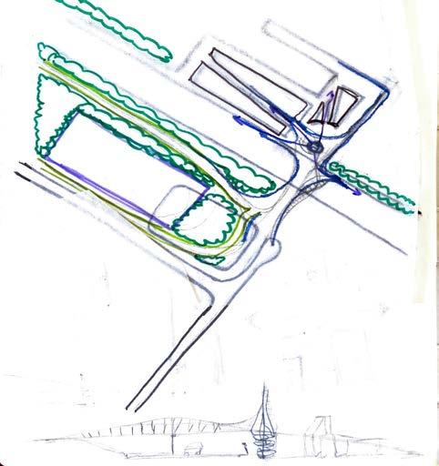
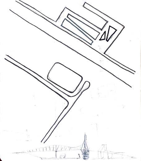
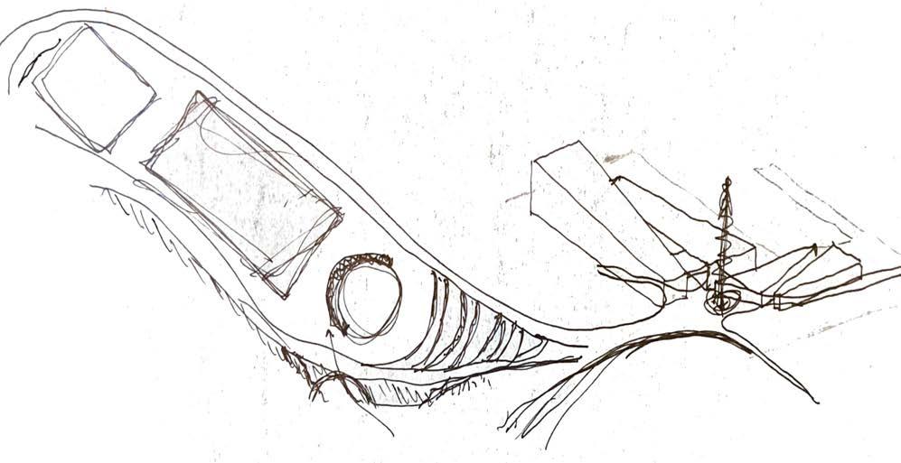
The follwing images on page 168-171 are the process drawings of my project. Each drawing tackles different site elements throughout the project. A lot of this drafting and sketching would help me out in keying in on finalizing a pure design form that relate to the site and impact the community. As well as designing element of interaction. Also creating connection pieces to circulate people from one end to another.

166
CONCEPTUAL
LAND BRIDGE
SITE AXON DRAWING
SITE PLAN 1
SITE PLAN 2
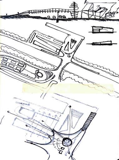
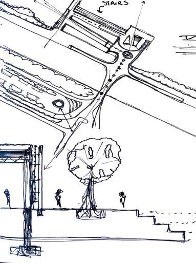
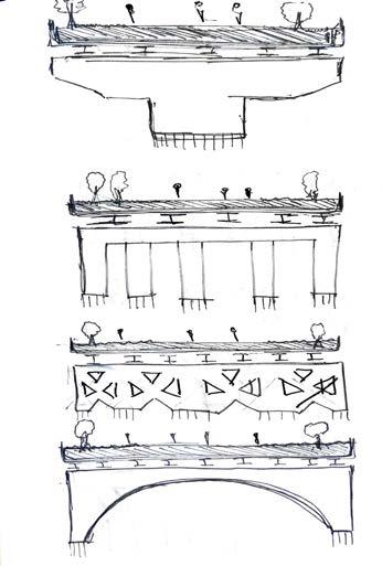
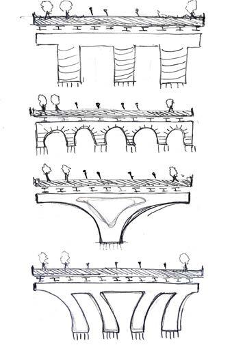
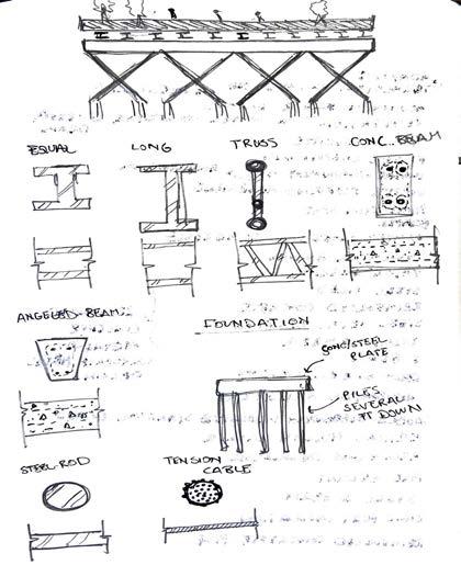
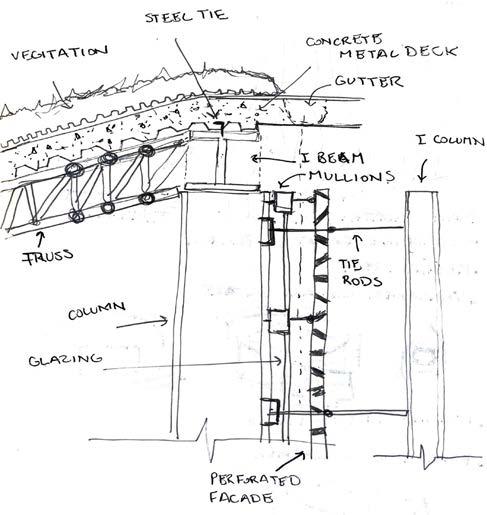
167 PLAN + SECTION 1 PLAN + SECTION 2 CONCEPT BRIDGE FORM 1 CONCEPT BRIDGE FORM 2 CONCEPT BRIDGE STRUCTURE CONCEPT DEATIL WALL SECTION
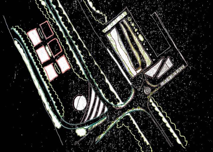
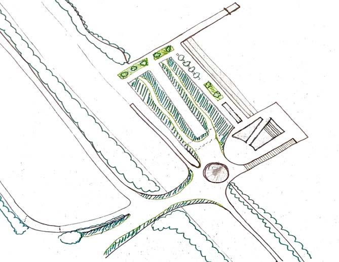
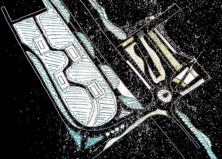
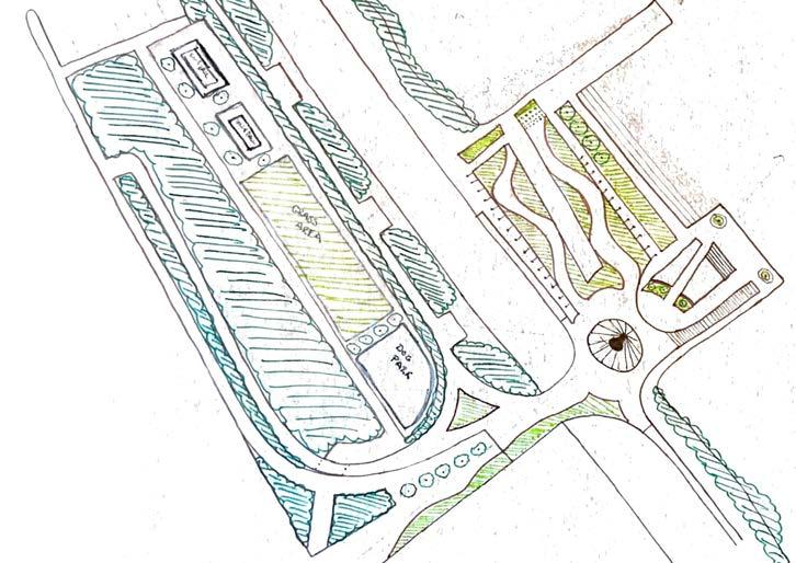
168 PROCESS TRACE SITE DIAGRAMS SITE PLAN 1 SITE PLAN 2 SITE PLAN 5 SITE PLAN 6
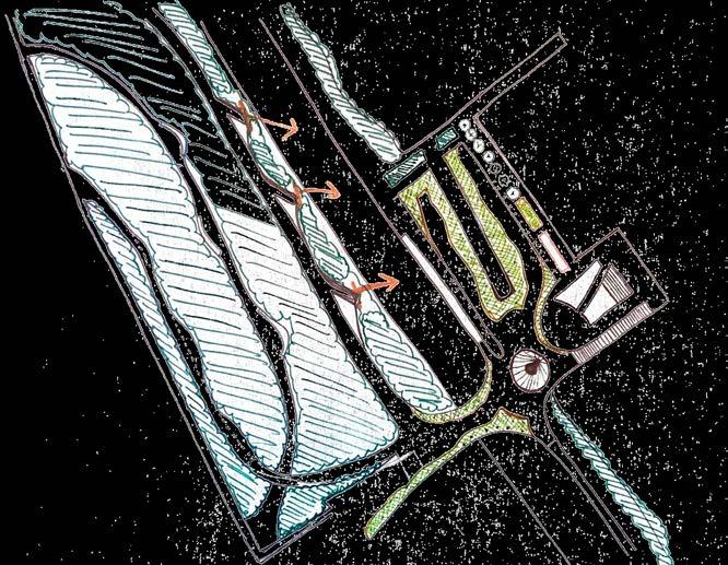

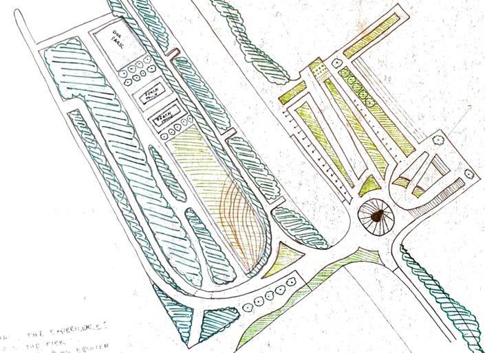
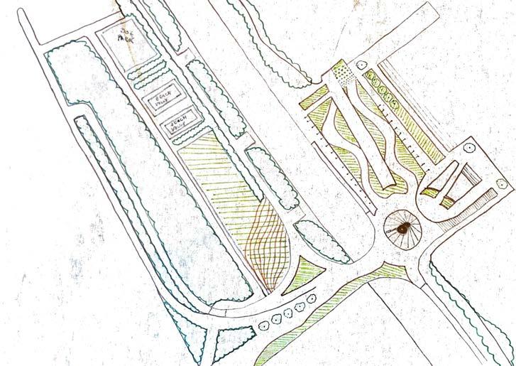
169 SITE PLAN 3 SITE PLAN 4 SITE PLAN 7 SITE PLAN 8
Each process model created on the right helped visualize the what. What the site is. What is needed and whether or not it is worth doing some of the design moves intented from the beginning of the project
Each model creates a moment where the building touches the water. Each placed on a pier
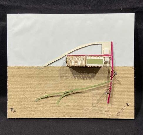
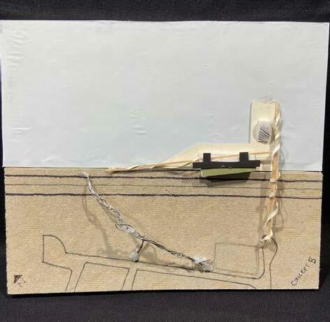
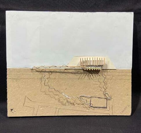
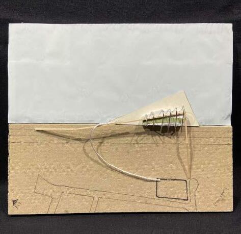
Each pier creates a different shape based on the buildings form due to it site and climate impacts
Within theses models the notion to create a bridge or path is important. The only access to get to the site is either over the highway or the use of an existing pedestrian path located along the water which is entered on the far ends of the site
“ To design a building which impacts the site through interaction, connection and community by exploring ornamentation and structural expression.”
170 CONCEPTUAL MODELS
CONCEPT 5 CONCEPT 6 CONCEPT 1 CONCEPT 2
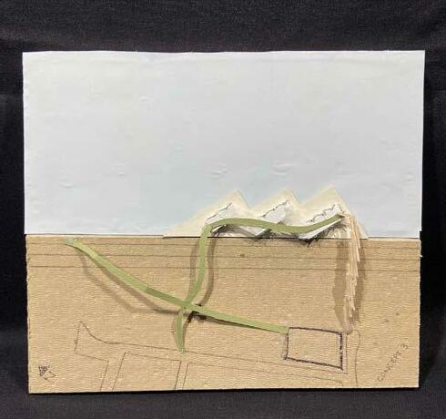
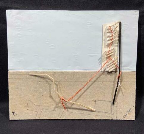
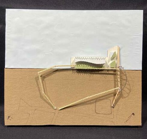
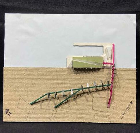
171 CONCEPT 7 CONCEPT 8 CONCEPT 4CONCEPT 3
INTERACTION COMMUNITY
CONNECTION INTERACTION COMMUNITY CONNECTION
Throughout the semester the original symbolic precedent has changed and morphed to a representation that correlates with both building, site and a land mark element. While listening to many of the reviewers, professors and my fellow peers I took a step back and analyzed the site. Looking at how I could explore the “what the site needs”, to increase pedestrian usage and interaction with elements that cohesively balance building and space. Three words that came into mind while looking at the past precedents becomes the foundation of what I need to design towards. Connection, Interaction and Community. These three ideas signify how I should approach my design. Also how these words could be a design bases for certain spaces.
At the middle of these three words a node. This node would be a representation of a land mark element, a structural column, which symbolizes placement of building. This element becomes the center peace of joining many of the sites elements and programing of the building. Each dashed red line starts to represent design features that symbolically connect to the node.
COMMUNITY
CAFELANDBRIDGE
On one of the red lines the land bridge starts to form making its way over the highway. The two other lines split the program. This would help soften the building mass and help spill the program on the waterfront. This splitting of the program would help in creating interactive elements in and around the buildings. The land bridge would start to take shape and morph on some of the buildings program while creating ramps and stair cases. At the center of it all the node, the land mark piece which holds up part the bridge and metaphorically holds up part of the projects design.
172 PROCESS DIAGRAMS
INTERACTION
CONNECTION REC. 1 REC. 2 MUSEUM
TILT SLICE SUBTRACT
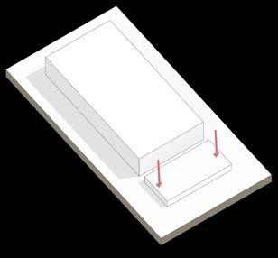

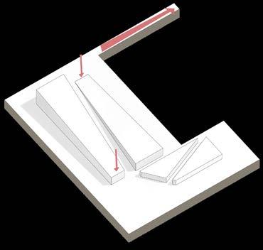
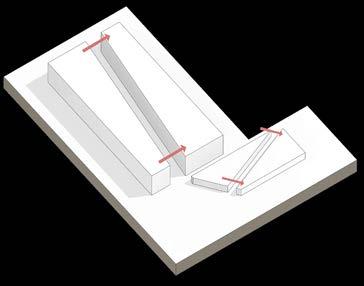
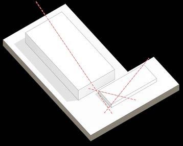
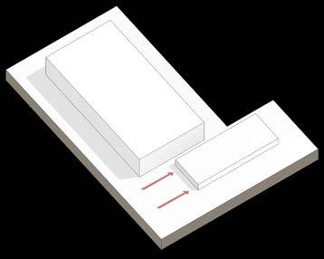
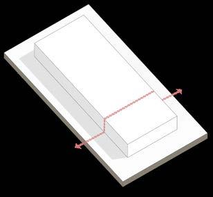
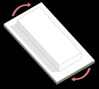
173
SHIFT DIVIDE PULL SLOPED ROOF + PLINTH GREEN ROOF + STAIRS FORM DIAGRAMS
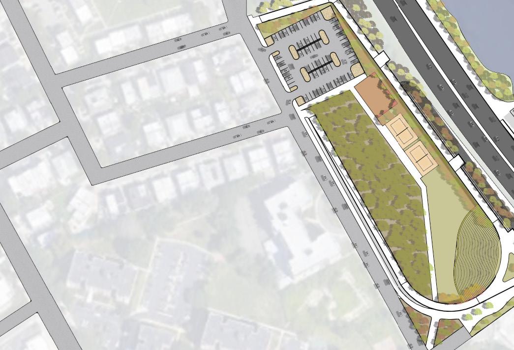

174 SITE PLAN DOG PARK BEACH VOLLY BALL COURTS GRAND LAWN FORESTED AREA OUTDOOR SEATING PARKING(PREVIOUSPAVING) XERISCAPINGEVSTATIONS 0’ 40’ 160’80’
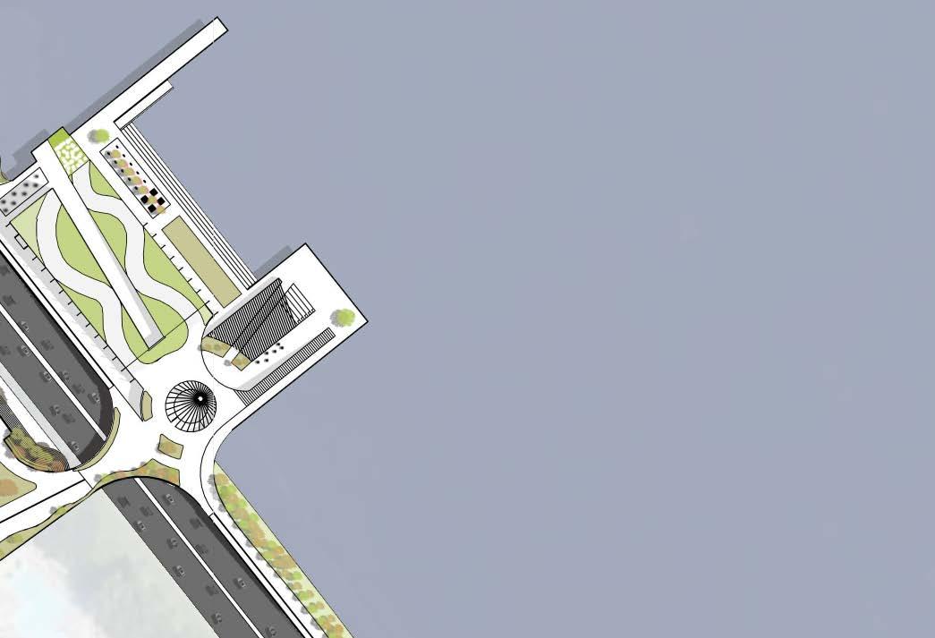
175 LAND MARK STRUCTURAL COLUMN AMPHITHEATER MOUNDED LAWN GIANT CHESS / CHECKERS CHESS / CHECKERS KAYAKRAMPCHECKERED VEGITATION SLOPING GREEN ROOF PEDESTRIANPATH LANDBRIDGE EXTERIORGRANDSTAIRCASE CROSS ISLAND PARKWAY 2. Recreation space ( soccer, lacrosse, field hockey ) 3. Museum/ small theatre 4. Cafe 7. Multipurpose rooms 11. Private alcoves 19. Janitor closet 13. Pent house 17. Kayak / equipment storage 14. Reception 12. Lounge area 9. Observation area 8. Library 5. Multi changing food stations 1. Recreation space ( basketball, volleyball ) 6. Dining / kids play space 15. Offices 10. Work stations 20. Bathroom 18. Storage 16. Mechanical / electrical BUILDING PROGRAM PIER
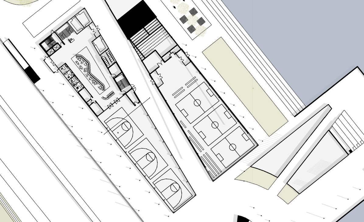

176 FIRST FLOOR 0’ 20’ 60’ 1 2 3 4 5 5 5 6 9 14 15 16 16 16 17 18 19 20 20 20 2. RECREATION SPACE ( SOCCER, LACROSSE, FIELD HOCKEY ) 3. MUSEUM/ SMALL THEATRE 4. CAFE 7. MULTIPURPOSE ROOMS 11. PRIVATE ALCOVES 19. JANITOR CLOSET 13. PENT HOUSE 17. KAYAK / EQUIPMENT STORAGE14. RECEPTION 12. LOUNGE AREA9. OBSERVATION AREA8. LIBRARY 5. MULTI CHANGING FOOD STATIONS1. RECREATION SPACE ( BASKETBALL, VOLLEYBALL ) 6. DINING / KIDS PLAY SPACE 15. OFFICES 10. WORK STATIONS 20. BATHROOM18. STORAGE16. MECHANICAL / ELECTRICAL BUILDING PROGRAM
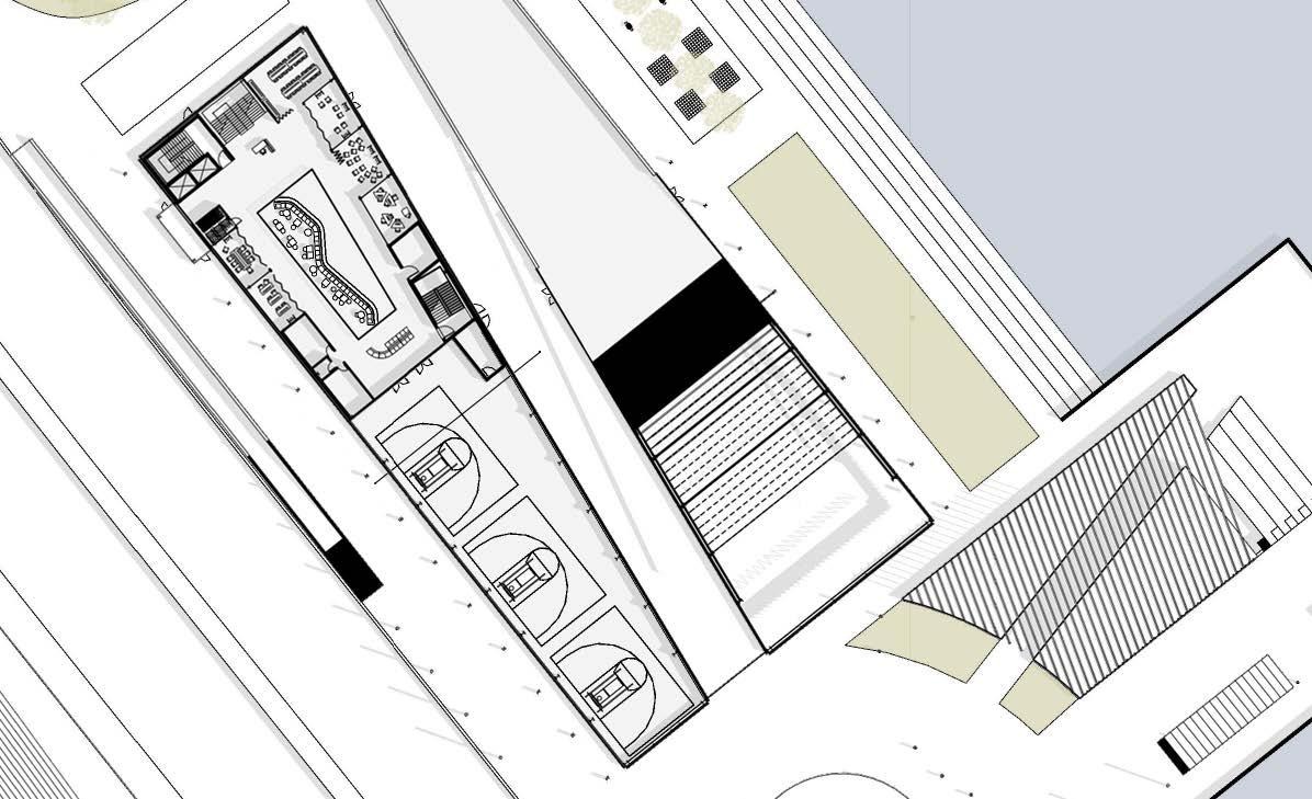
177 SECOND FLOOR 0’ 20’ 60’ 7 7 7 7 7 9 14 16 18 7 19 20 20 2. RECREATION SPACE ( SOCCER, LACROSSE, FIELD HOCKEY ) 3. MUSEUM/ SMALL THEATRE 4. CAFE 7. MULTIPURPOSE ROOMS 11. PRIVATE ALCOVES 19. JANITOR CLOSET 13. PENT HOUSE 17. KAYAK / EQUIPMENT STORAGE14. RECEPTION 12. LOUNGE AREA9. OBSERVATION AREA8. LIBRARY 5. MULTI CHANGING FOOD STATIONS1. RECREATION SPACE ( BASKETBALL, VOLLEYBALL ) 6. DINING / KIDS PLAY SPACE 15. OFFICES 10. WORK STATIONS 20. BATHROOM18. STORAGE16. MECHANICAL / ELECTRICAL BUILDING PROGRAM
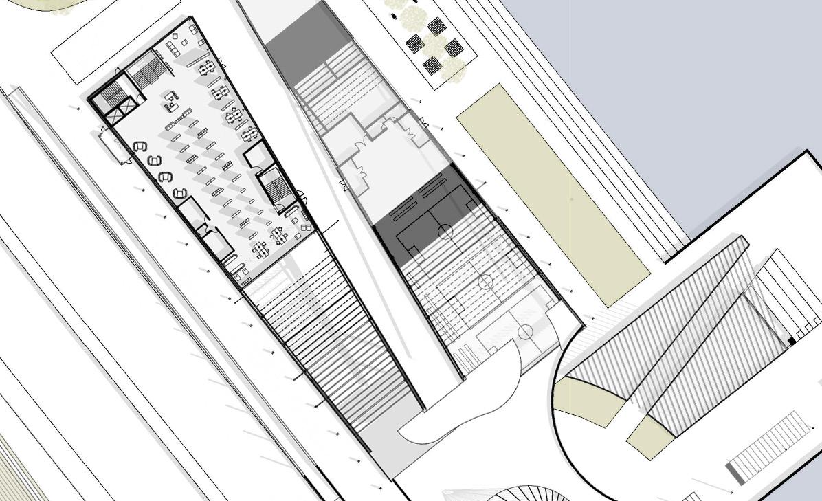
178 THIRD FLOOR 0’ 20’ 60’ 8 9 10 10 11 12 12 12 14 16 19 20 20 2. RECREATION SPACE ( SOCCER, LACROSSE, FIELD HOCKEY ) 3. MUSEUM/ SMALL THEATRE 4. CAFE 7. MULTIPURPOSE ROOMS 11. PRIVATE ALCOVES 19. JANITOR CLOSET 13. PENT HOUSE 17. KAYAK / EQUIPMENT STORAGE14. RECEPTION 12. LOUNGE AREA9. OBSERVATION AREA8. LIBRARY 5. MULTI CHANGING FOOD STATIONS1. RECREATION SPACE ( BASKETBALL, VOLLEYBALL ) 6. DINING / KIDS PLAY SPACE 15. OFFICES 10. WORK STATIONS 20. BATHROOM18. STORAGE16. MECHANICAL / ELECTRICAL BUILDING PROGRAM
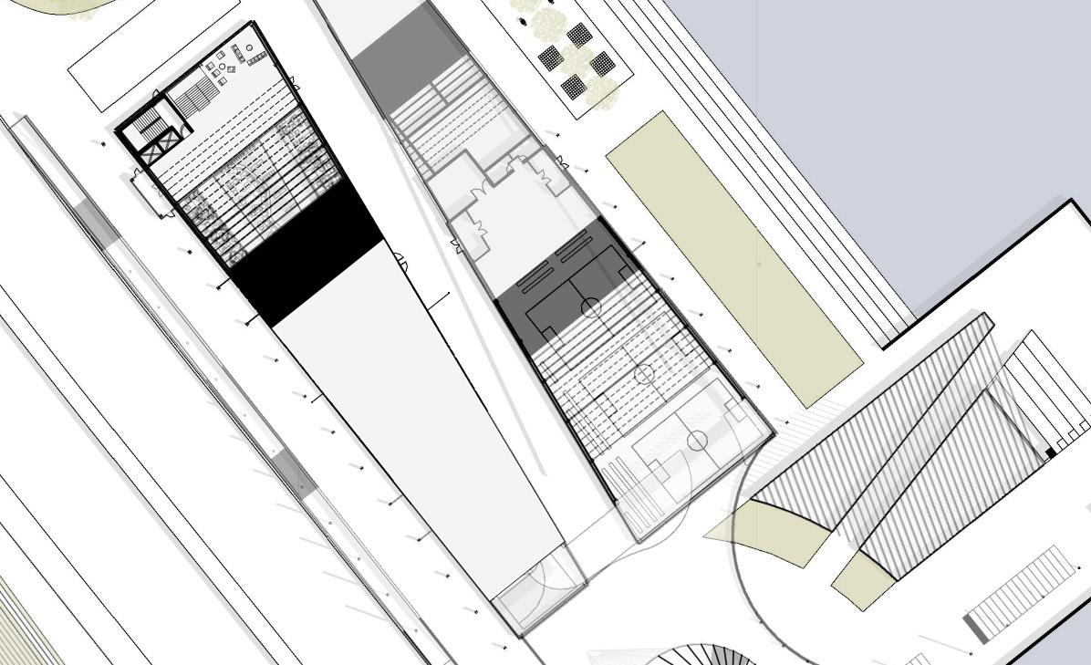
179 FOURTH FLOOR 0’ 20’ 60’ 9 13 2. RECREATION SPACE ( SOCCER, LACROSSE, FIELD HOCKEY ) 3. MUSEUM/ SMALL THEATRE 4. CAFE 7. MULTIPURPOSE ROOMS 11. PRIVATE ALCOVES 19. JANITOR CLOSET 13. PENT HOUSE 17. KAYAK / EQUIPMENT STORAGE14. RECEPTION 12. LOUNGE AREA9. OBSERVATION AREA8. LIBRARY 5. MULTI CHANGING FOOD STATIONS1. RECREATION SPACE ( BASKETBALL, VOLLEYBALL ) 6. DINING / KIDS PLAY SPACE 15. OFFICES 10. WORK STATIONS 20. BATHROOM18. STORAGE16. MECHANICAL / ELECTRICAL BUILDING PROGRAM
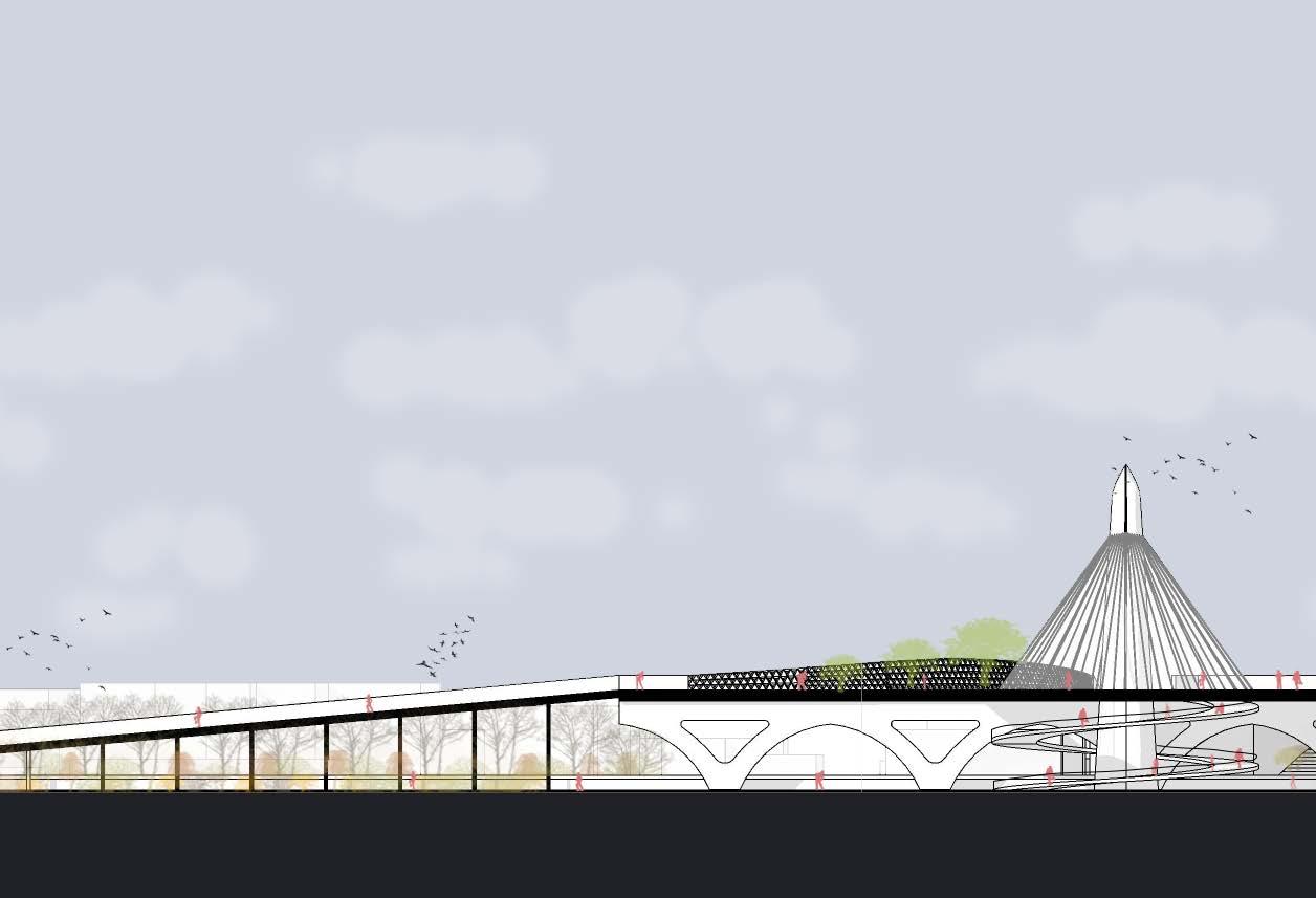
180 SOUTH WEST SECTION 0’ 20’ 60’
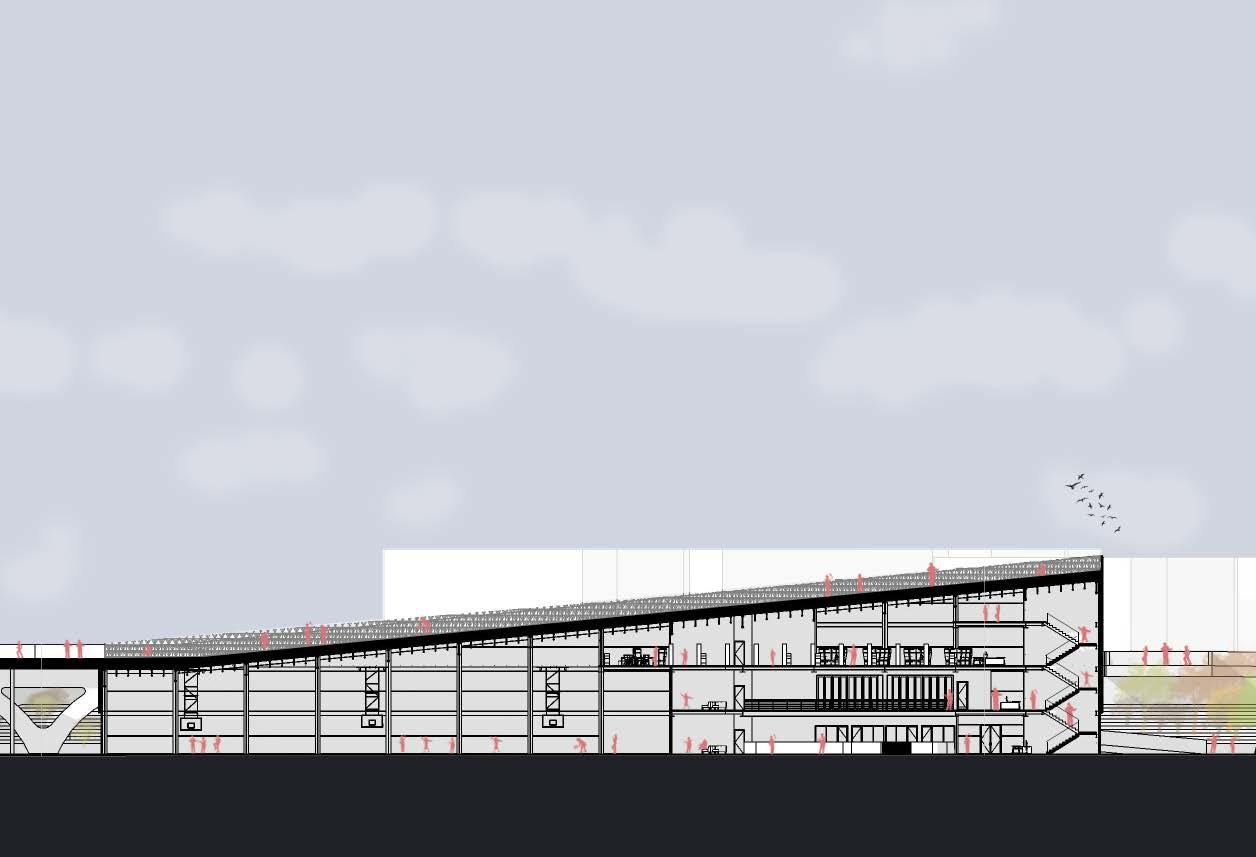
181
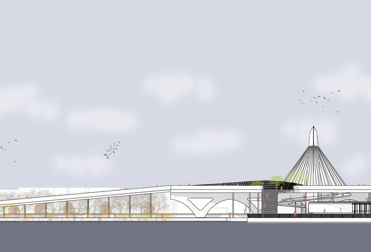
182 SOUTH WEST ELEVATION 0’ 20’ 60’
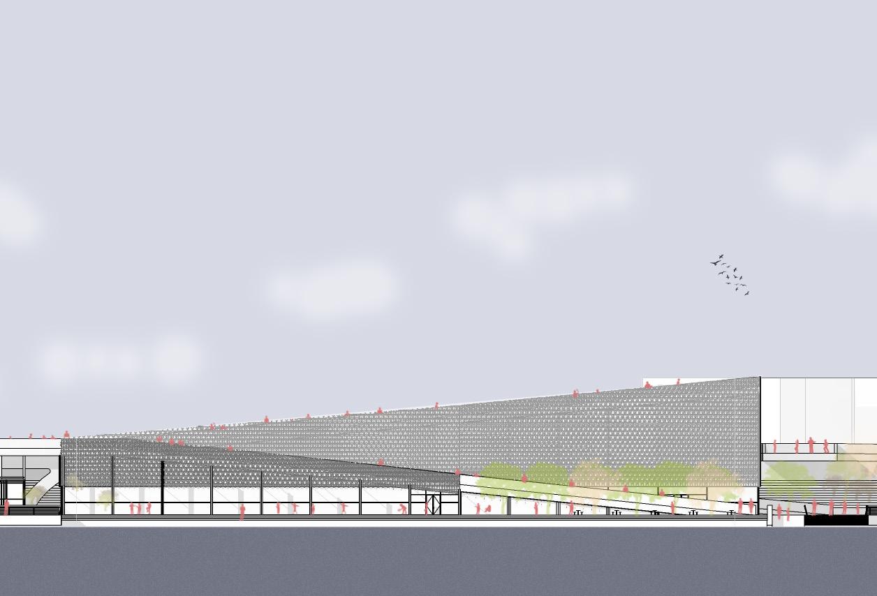
183
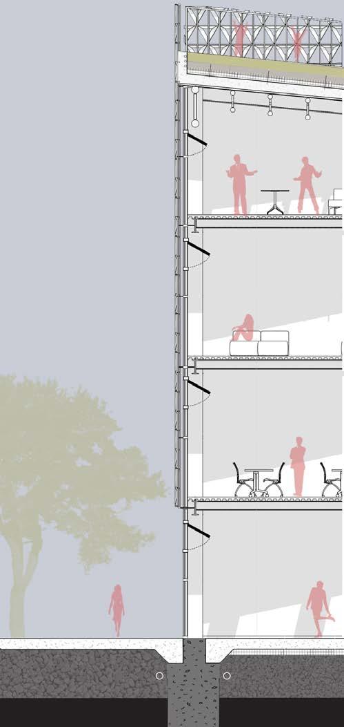
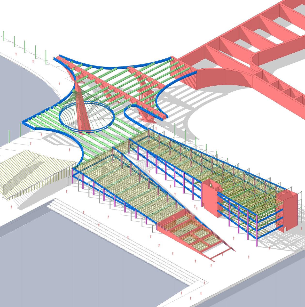
184 Adaptive facade terracotta panel Steel clips for panel Aluminum frame mullions Vegetation Soil substrate Water collector gutter drain Filter sheathing Root barrier Drainage mat Water proofing membrane Protection mat Water proofing membrane Insulation barrier Vapor barrier Steel roof ties Roof reinforced concrete Corrugated steel decking 4’ deep steel truss W 10x33 HP 18x181 Horizontal mullion cap Double insulated spandral glass Vertical mullion anchor Argon gas insulator Fire sealant Mullion insulation Recycled concrete slab Window Rigid insulation Drainage Gravel Reinforced concrete pile W 14 x 68 5” concrete metal decking DETAILED WALL SECTION AXON STRUCTURAL DIAGRAM
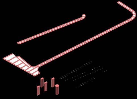
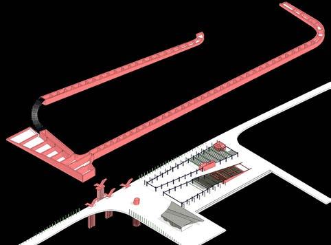
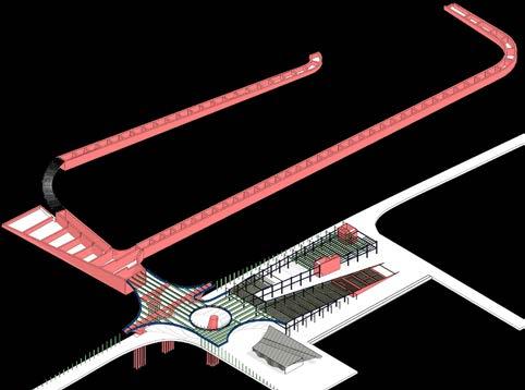

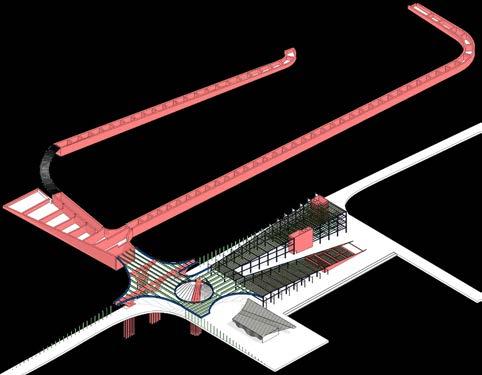
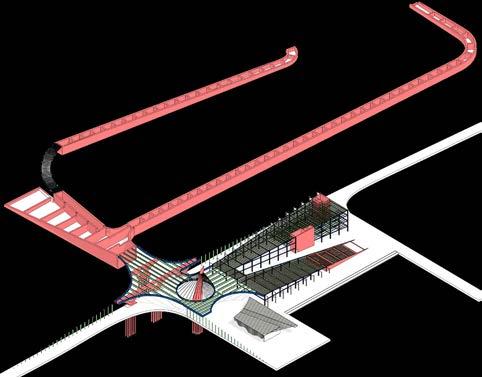
185 FINAL CONSTRUCTION PROCESS CONSTRUCTION PHASE 1 CONSTRUCTION PHASE 4 CONSTRUCTION PHASE 5 CONSTRUCTION PHASE 6 CONSTRUCTION PHASE 2 CONSTRUCTION PHASE 3
Throughout the building there are geothermal pump rooms, five to be exact. Each taking care of its own zone. Creating separate zones would allow the building to save energy. This would efficiently cool and heat the building.
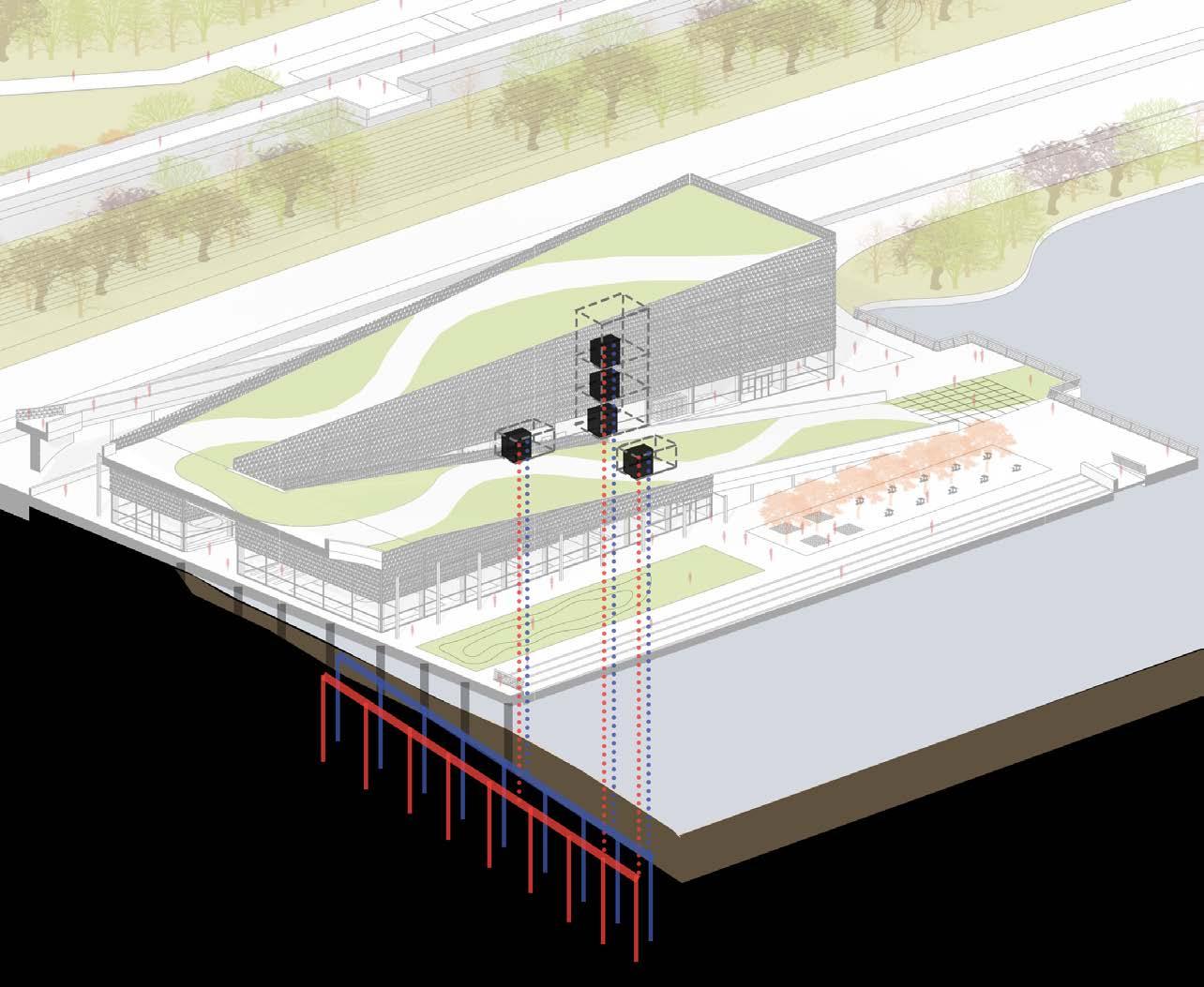
186 GEOTHERMAL DIAGRAM
Along the roof of the building between the facade, a gutter system allowing the water to slope down into a water chamber. In storage tanks water would be stores. It would irrigate the roof and some of the vegetation along the pedestrian walk way.
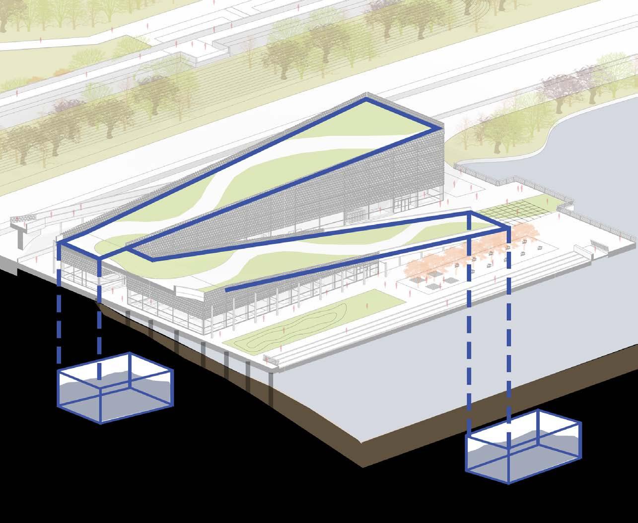
187 WATER COLLECTION DIAGRAM
PASSIVE COOLING /
This adaptive parametric facade creates a huge role into cooling the building. The facade could tighten up to take warm air from outside and cool it. Night purging becomes a huge contributor to this. It allows sun light manipulation. Becomes a shading element. By the use of a switch the panels would mechanically open or close due to its sophisticated programing. Also at the roof level the facade becomes a railing that could be an interactive feature because of its operability.
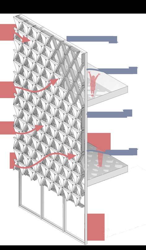
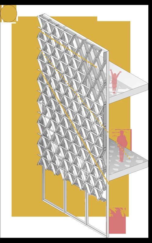
188
SHADING


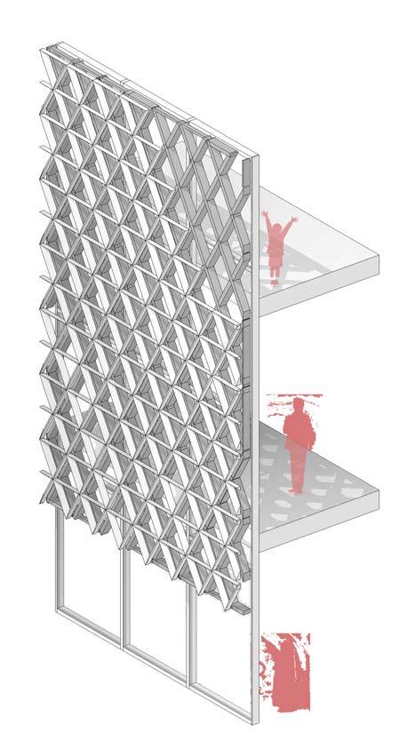
189 20% OPEN 45 % OPEN 75% OPEN ADAPTIVE FACADE
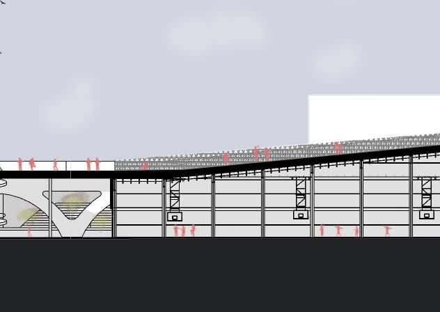

190 SUSTAINABLE SECTION WATER COLLECTION 0’ 20’ 60’
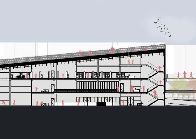
191 GEOTHERMAL VERTICAL LOOPS PASSIVE COOLING

192 LEED V4 CHECKLIST LEED v4 for BD+C: New Construction and Major Renovation Project Checklist Peir 24: Community Hub Y?N 1 Credit 1 709 16805 13 Credit 16 Y Prereq Required 1 Credit 1Y Prereq Required 2 Credit 25 Credit 5 23 Credit 52 Credit 2 14 Credit 52 Credit 2 10 Credit 12 Credit Building Product Disclosure and Optimization - Material Ingredients 2 1 Credit 12 Credit 2 1 Credit Green Vehicles 1 1501Indoor Environmental Quality 16 703 10 Y Prereq Required Y Prereq RequiredY Prereq Required 1 Credit 12 Credit 2 2 Credit 23 Credit 3 1 Credit 11 Credit Construction Indoor Air Quality Management Plan 1 3 Credit 32 Credit 2 2 Credit 21 Credit 1 1 Credit 12 Credit 2 3 Credit 3 506 11 1 Credit 1 Y Prereq Required 1 Credit 1 Y Prereq Required Y Prereq Building-Level Water Metering Required 600Innovation 6 2 Credit 25 Credit 5 24 Credit 61 Credit 1 2 Credit 2 1 Credit Water Metering 1 400Regional Priority 4 1 Credit Regional Priority: Specific Credit 1 3003 33 1 Credit Regional Priority: Specific Credit 1 Y Prereq Required1 Credit Regional Priority: Specific Credit 1 Y Prereq Required1 Credit Regional Priority: Specific Credit 1 Y Prereq Required Y Prereq Required 83 0 27 TOTALS Possible Points: 110 6 Credit 6 18 Credit 18 1 Credit 1 2 Credit 2 21 Credit 3 1 Credit 1 2 Credit 2 Site Development - Protect or Restore Habitat Building Product Disclosure and Optimization - Sourcing of Raw Materials Project Name: Date: Location and Transportation Sensitive Land Protection LEED for Neighborhood Development Location Bicycle Facilities Construction and Demolition Waste Management Planning Materials and Resources Storage and Collection of Recyclables Construction and Demolition Waste Management Minimum Indoor Air Quality Performance Building Product Disclosure and Optimization - Environmental Product Declarations Integrative Process Construction Activity Pollution Prevention High Priority Site Surrounding Density and Diverse Uses Sustainable Sites Building Life-Cycle Impact Reduction Green Power and Carbon Offsets Heat Island Reduction Outdoor Water Use Reduction Indoor Water Use Reduction Outdoor Water Use Reduction Indoor Water Use Reduction Enhanced Commissioning Building-Level Energy Metering Water Efficiency Fundamental Commissioning and Verification Demand Response Renewable Energy Production Enhanced Refrigerant Management Optimize Energy Performance Advanced Energy Metering Certified: 40 to 49 points, Silver: 50 to 59 points, Gold: 60 to 79 points, Platinum: 80 to 110 Access to Quality Transit Reduced Parking Footprint Open Space Site Assessment Interior Lighting Daylight LEED Accredited Professional Innovation Rainwater Management Light Pollution Reduction Environmental Tobacco Smoke Control Energy and Atmosphere Minimum Energy Performance Fundamental Refrigerant Management Cooling Tower Water Use Acoustic Performance Quality Views Enhanced Indoor Air Quality Strategies Low-Emitting Materials Indoor Air Quality Assessment Thermal Comfort LEED PLATINUM


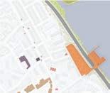

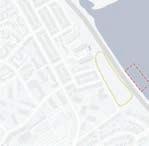

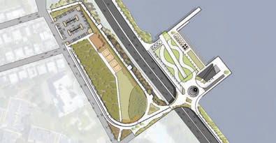

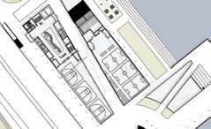
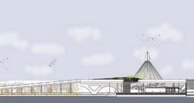
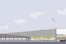


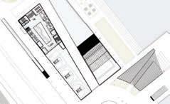
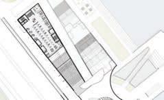
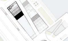
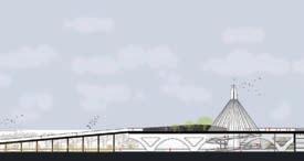
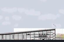


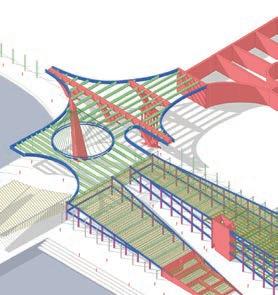


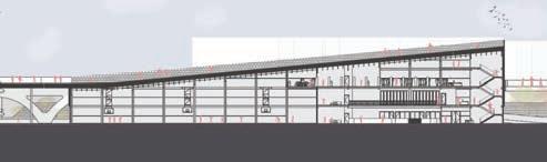


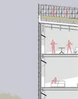
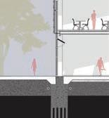
193 PRESENTATION BOARDS SITE LOCATION SITE ANALYSIS SITE INVENTORY PROCESS DIAGRAM CONCEPT MODELS PIER 24: COMMUNITY HUB PRECEDENTS Structural expression tells the story about the building’s interior and exterior components Ornamentation becomes the beauty and the subtle softness of the building’s exterior compostions Double heighted spaces allow connection above and below Recreation spaces become part of the building’s form as well as bleed into the interior Facades become part of an interactive element in order to create an experience to excite and draw attention to the user Bridges create access from one place over another in order to create cohesive, connecting corridors CREATIVE JUNGLE VERSITILE PAVILLION TCDC KHON KAEN MODULAR FRAMEWORK THE CONNECTION TO RHODES PERGOLA LUOTUOWAN VILLAGE HUNTERS POINTARCH WILD LIFE CROSSING FRANCIS APPLETON BRIDGE Ornamentation Facade Interaction Structure Interaction Program SplitingTransparency ACTIVE HUB Structural Expression InteractionConnection CommunityDouble Heighted Space UNITED STATES NEW YORK QUEENS, NEW YORK DOUGLASTON, LITTLE NECK CONCEPT CONCEPT 8 CONCEPT 4 CONCEPT 5 CONCEPT 6 CONCEPT 1 CONCEPT 2 CONCEPT Each process model created on the right helped visualize the what What the site is. What is needed and whether or not is worth doing some of the design moves intented from the beginning of the project Each model creates moment where the building touches the water. Each placed on pier Each pier creates different shape based on the buildings form due to it site and climate impacts Within theses models the notion to create bridge or path is important. The only access to get to the site is either over the highway or the use of an exsiting pedestrain path located along the water which is entered on the far ends of the site To design a building which impacts the site through interaction, connection and community by exploring ornamentation and structural expression.” TILT SLICE SUBTRACT SHIFT DIVIDE PULL SLOPED ROOF + PLINTH GREEN ROOF + STAIRS INTERACTION COMMUNITY CONNECTION INTERACTION COMMUNITY CONNECTION INTERACTION COMMUNITY CONNE TION REC. 1 REC. 2 MUSEUM CAFELANDBRIDGE SITE BAY TERRACE SHOPPING CENTRE 24 BELL ACADEMYQUEENS PUBLIC LIBRARY AT BAY TERRACE BAYSIDE MARINA FORT TOTTEN MILITARY BASE/ PARK DENTIST/ ORTHODONTIST/ PLASTIC SURGERY/ DERMATOLOGISTRESIDENCIAL BUILDINGS 13 BUS STOPS SITESCHOOL CROSS ISLAND PARKWAY PEDESTRIAN WALK WAY Access from highway and exsiting pedestrain Military base for navy. Military academy training. Also park certain A node essentially Community hub which touches the water and the pedestrain walkway connects bridge. goal interaction, connection and communiy, the bases marina Aixal path from shoping center and bus route to the end of the road. huge opportunity. How could we get across joining the bridge over highway Forested area great potential use Cross island parkway, leads long island, Manhattan THIRD FLOOR FOURTH FLOOR FIRST FLOOR SECOND FLOOR SECTION SOUTH WEST ELEVATION SOUTH WEST SECOND FLOOR INTERIOR EXTERIOR PEDESTRIAN TRAIL SITE PLAN B A HVVO L OU T RA DL WN U M AM HTH A N KAAKRRAMP H CHCK EDV V ATON S O GG G E N OO OU OOR E EA NG G P D T AH LANDBR R TE O G ARCCAS 10 10 11 12 12 14 14 16 16 16 16 16 18 19 19 20 20 20 20 P NG ER O V X NG T RO S S NDP R A .RECREATION SPACE OCCER, LACROS FIELD HOCKEY EUM/ SMALL .MU IP RP OO 3.PENT HOUS 7.KAYAK EQUIPMENT STO AGE 2.LOUN ARE .MUL ICHANGING FOOD STATIONS .DINING KID PLA SPAC .WO STATIONS .BATHROO 6. MECHANICAL ELECTRICA UILDING PROGRAM AXON STRUCTURE SECTION: SUSTAINABILITY GEOTHERMAL PASSIVE COOLING/ SHADING WATER COLLECTION WATER COLLECTION GEOTHERMAL VERTICAL LOOPS PASSIVE COOLING Along the roof of the building between the facade, gutter system allowing the water to slope down into a water chamber. A tank under ground would store, irrigate the roof and some of the vegetation along the pedestrian walk way. Throughout the building there are geothermal pump rooms four to be exact. Each taking care of its own zone. creating separte zones would allow the building to save energy. This would efficently cool and heat the building. This adaptive parametric facade creates a huge role into cooling the building. The facade could tighten up to take warm air from outside and cool it. Night purging becomes huge contributor to this. It allows sun light minipulation. Becomes a shading element. EXTERIOR SLOPED ROOF ADAPTIVE FACADE TERRACOTTA PANEL STEEL CLIPS FOR PANEL ALUMINUM FRAME MULLIONS VEGITATION SOIL SUBSTRATE WATER COLLECTOR GUTTOR DRAIN FILTER SHEATHING ROOT BARRIER DRAINAGE MAT WATER PROOFING MEMBRANE PROTECTION MAT WATER PROOFING MEMBRANE INSULATION BARRIER VAPOR BARRIOR STEEL ROOF TIES ROOF REINFORCED CONCRETE CORRUGATED STEEL DECKING DEEP STEEL TRUSS W 10x33 HP 18x181 HORIZONTAL MULLION CAP DOUBLE INSULATED SPANDRAL GLASS VERTICAL MULLION ANCHOR ARGON GAS INSULATOR FIRE SELANT MULLION INSULATION RECYCLED CONCRETE SLAB WINDOW RIGID INSULATION DRAINAGE GRAVEL REINFORCED CONCRETE PILE W 14 68 5” CONCRETE METAL DECKING
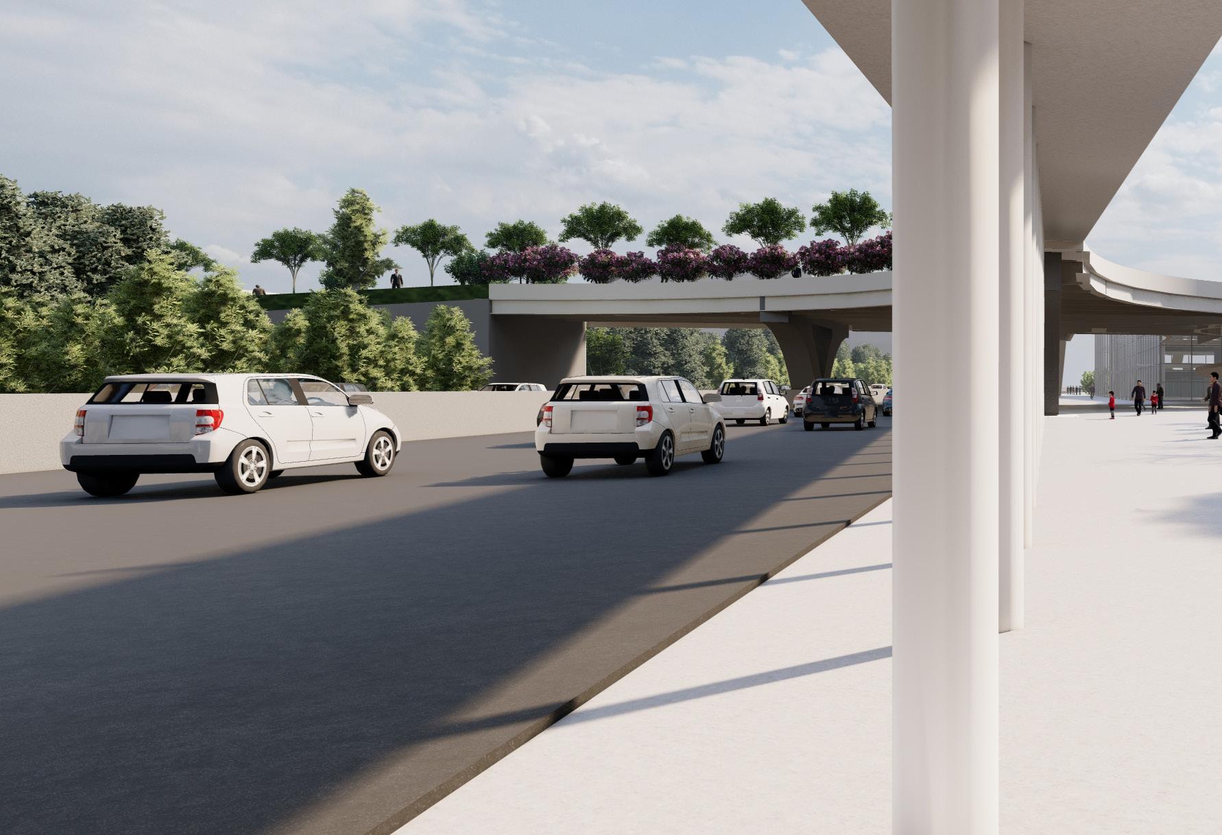
194 EXTERIOR PEDESTRIAN WALK WAY
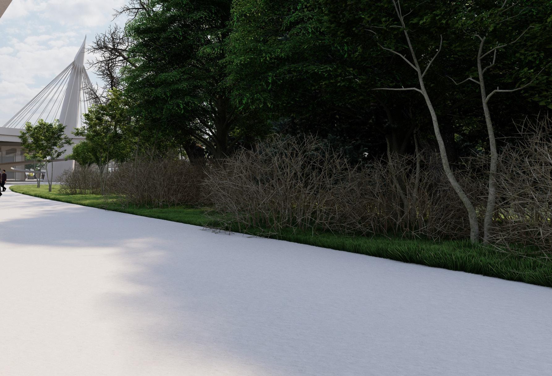
195
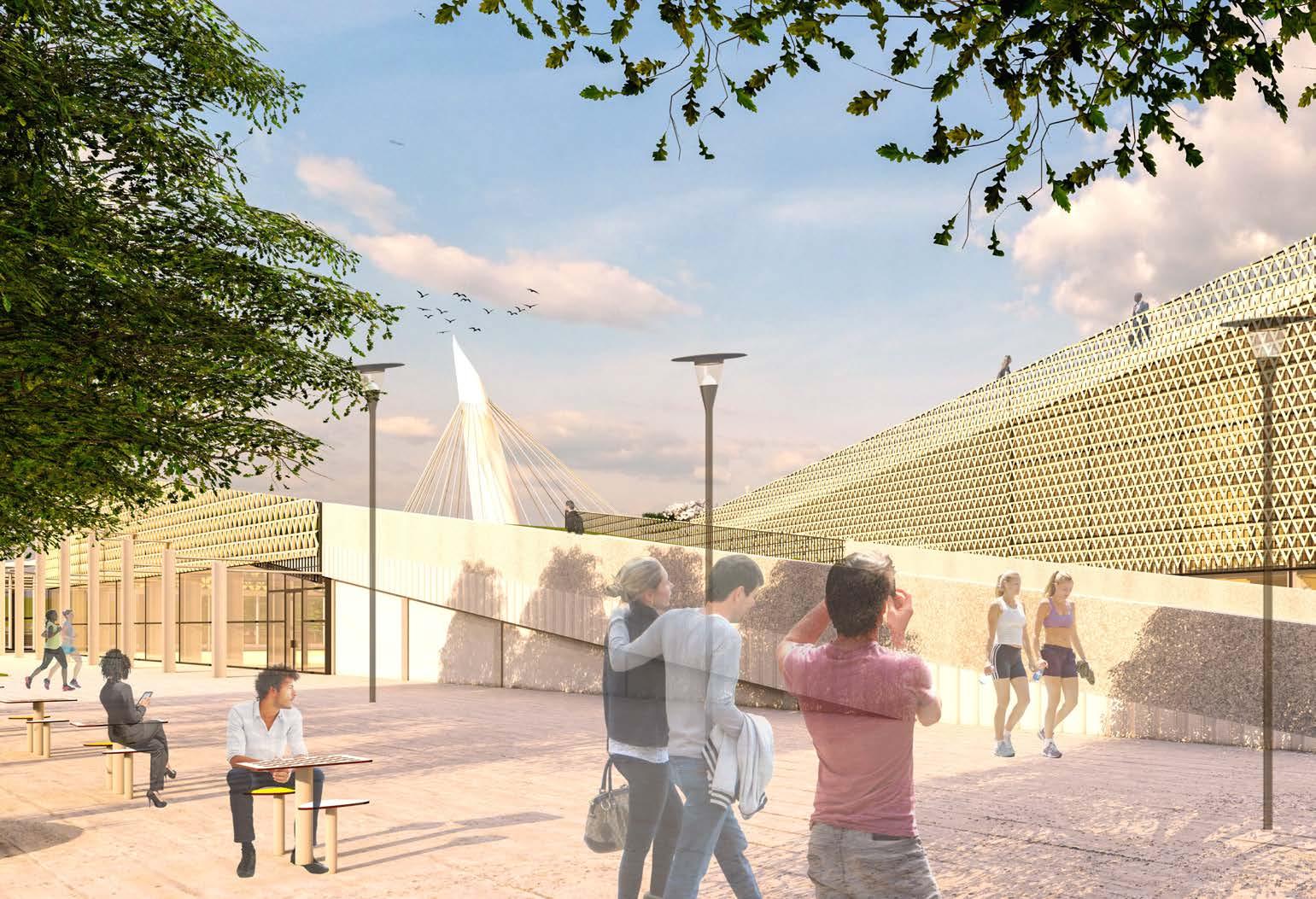
196 EXTERIOR SLOPED ROOF
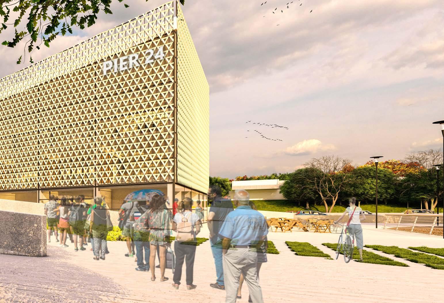
197
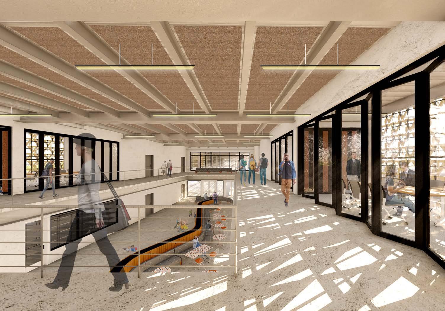
198 SECOND FLOOR INTERIOR
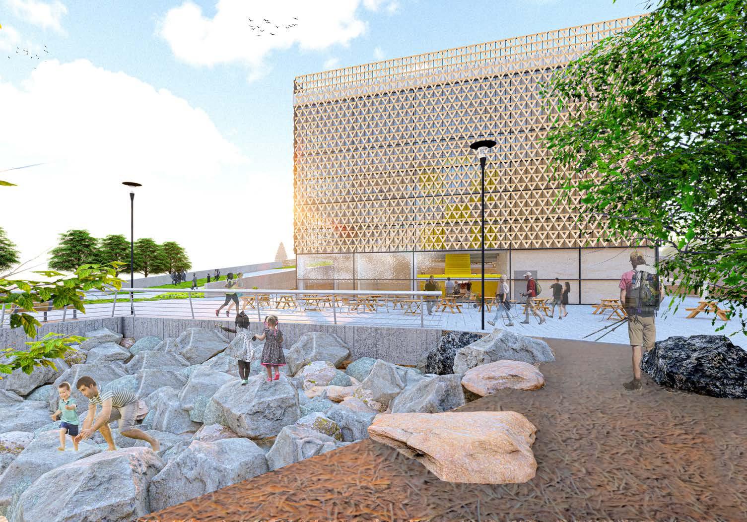
199 EXTERIOR PEDESTRIAN TRAIL
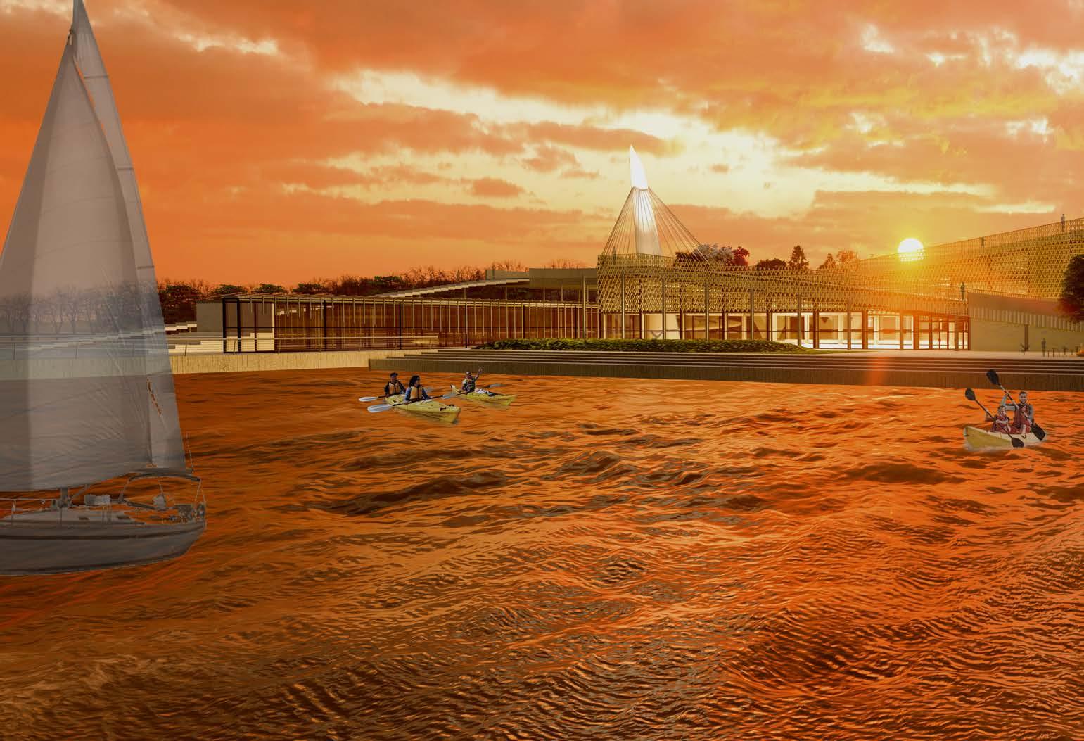
200 EXTERIOR VIEW ON THE PLINTH
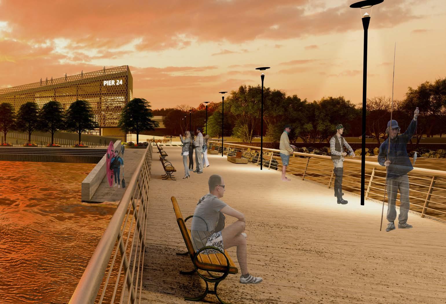
201
POSITION PAPER
COMMUNAL HUB POSITION PAPER
BUILDING TYPE
A community hub, also referred to as a community center is a building or structure which provides a multi use of activities. Such as medical centers, multipurpose centers, community centers or a school. These genres of building types within the communal hub category help obtain goods and services which are helpful and or utilized by any of the near by communities. It is a place where a public space could potentially enhance neighborhoods / communities by using a range of programs within the space. It is to emphasize better public accessibility, interaction and gatherings under a roof of a structure. They are led by people that are involved with running the programs and services within the building. They are carried out by people volunteering or be used by a public agency such as an authority that has a big input towards the community. Its the effort to create a building that hones sustainability factors which help the environment and educate the public about clean energy. The gathering of people for social connection and interaction through the use of public activities. These are important goals that I’d like to achieve through my design.
HISTORY
Fort Totten is located along the Cross Island Parkway due east. It was once a destination where the Matinecock Indians lived. During the American Revolution, Fort-Totten it was once called Willets point. This resembles the other Willets point in queens located near Manhattan ( only a transit stop away). The name of this base came to be because of general Joseph Totten in 1788 - 1896. Fort Totten had been in charge of fortifying the eastern part of the bayside area to the New York harbor. It then became unused because of the civil war. It was used as a place for hospitalization and casualty support. After the wars this base housed many, nurses doctors and soldiers. For example, “ The engineer school of application, Eastern Artillery District Headquarters, Electric Mines and Army School of Submarine Defense, prototype anti-aircraft installation, the Anti-Aircraft Artillery Headquarters, the North Atlantic Wing of the Air Transportation Command, the New York-New jersey Sub-Area Command Headquarters, First Region ARADCOM for the Nike Anti-Ballistic
Missile Defense System, and a U.S. Army Reserve post”. Quoted from the article. (https://www.nycgovparks.org/parks/fort-totten-park/highlights/12150)
Bayside was once a summer resort because of its vast amounts of mansions and its vicinity to the water. Today the base/ park is still being utilized by the department of the army and coast guard ( also utilized for other schools and event spaces), community events and a park.
THEORY : CONCEPT
Ornamentation is the addition of elements to create some structural form which creates a decorative design on the building. These would be categorized as meanings of symbolize, repetition or ornament. This would help add beauty to the applied structure through materials. Structural expression is the idea to take the bones of the buildings and express them on the facade of the building. Mechanical features as well as structural features would express the buildings look in a unique way. From the concept of ornamentation and structural expression this building and site would create unique experiences when approaching it. Could be seen by the pedestrian walkway or land bridge This method will inform how the building would sit on the site and how its facade could create complex exterior features which catch the users eye. The building could blend with both the water front and the residential side of the site. The facades detailing as well as interior finishes would help explore how materiality of the building could become a central piece of communal integration and interaction. An eye catching moment when seeing the building, seeing how it bleeds into the water and stretches into the residential side (over the highway) become an expressive moment that attracts the eye.
INTERACTION / CONNECTION / COMMUNITY
Interaction is an exchange of information between two people for information or physical acts with people. Connection is the ability to bridge one place to another with a matter of a structure or path. Community is a group of people living in the same place or having a particular characteristic in common. The building would create an interactive feature by applying public outdoor and
204
Indoor activities to promote this engagement between people. The connection aspect of the project is to propose a pedestrian foot bridge which creates a link to the residential side to the site. This bridge is elevated over the highway. The land bridge would be a huge feature for an influx of people pooling into the proposed communal hub. Easy access for people to approach Fort Totten and the Marina is also an important factor. The communal aspect of the project is to create unique spaces on this foot bridge and around the buildings footprint. To create a pooling effect towards the building, out and indoor activities. Being able to give back to the community.
CONCLUSION
To social interaction, connection, and community becomes different points of arrival and building form. This communal hub will be a building that would entice people to share time with one another and the site. The ability to create a location where people want to play, socialize, rest, ride their bikes, run etc, is a very powerful tool. Communal connection is a factor to where a successful building becomes timeless. It becomes a node where the building symbolizes a place of education, ceremonial space and adventure. All in all, these ideas are backed by three simple words. Interaction. Connection. Community.
205
ACKNOWLEDGMENT
I want to just thank everyone who has been involved with my project since the beginning. I want to thank my thesis professors Daniel Davis and Mark Hopper. Their push and enthusiasm inspired me to have fun designing my project throughout the semester.
I also want to thank all the professors from my previous semesters. Your drive during studio guided me to work even harder to produce great work. To all thank you so much. I am grateful to have been your student.
To my family and friends. I want to thank you all for sticking with me throughout all these years. Thank you. There is more to come.
208 ACKNOWLEDGMENT
“ Consequently, a well constructed model creates its own reality”
209 CLOSING STATEMENT
BIBLIOGRAPHY
REFERENCE PAGE
1. https://worldarchitecture.org/architecture-news/ cvvpg/winners-announced-for-creative-communityhub-to-design-an-urban-catalyst-in-adelaide.html
2. https://de51gn.com/architects49-draws-ontraditional-elevated-structures-to-create-contextualand-creative-community-hub-in-northeasternthailand/
3. https://www.archdaily.com/958384/springvalecommunity-hub-lyons
4. https://www.bdcnetwork.com/henning-larsendesigns-active-community-hub-london
5. https://www.nomastudio.com.au/work/14architecture/96-adelaide-creative-community-hub. html
6. https://worldarchitecture.org/architecture-news/ cvvpg/winners_announced_for_creative_community_ hub_to_design_an_urban_catalyst_in_adelaide.html
7. https://www.positive.news/environment/ sustainable-development/the-community-hub-madefrom-salvaged-wood/
8. https://www.dezeen.com/2017/02/22/spinellicommunity-centre-german-refugee-campmannheim-university-of-kaiserslautern/
9. https://localtrust.org.uk/news-and-stories/blog/ community-hubs-the-importance-of-developinga-sustainable-business-model/
10. http://www.luostudio.cn/project/2/113
11. http://www.a49.com/Projects/view/404
12. https://www.archdaily.com/963093/henninglarsen-designs-active-community-hub-as-theirfirst-london-project
13. https://henninglarsen.com/en/news/ archive/2021/06/07-victoria-street/ 14. https://www.lyonsarch.com.au/project/ springvale-community-hub/
15. https://www.archdaily.com/470878/cronepartners-rethink-the-community-centre-in-rhodes
16. https://crone.com.au/project/rhodescommunity-centre/ 17. https://furmancenter.org/neighborhoods/ view/bayside-little-neck
18. http://www.city-data.com/city/Queens-NewYork.html
19. https://en-us.topographic-map.com/maps/rf9l/ New-York/ 20. https://www.topozone.com/new-york/queensny/city/queens-2/ 21. https://dcp.maps.arcgis. com/apps/webappviewer/index. html?id=1c37d271fba14163bbb520517153d6d5
22. https://metroexplorer. planning.nyc.gov/welcome/ intro?narrativeVisible=false#7.29/40.857/-73.528
23. https://zola.planning.nyc.gov/ about/#9.72/40.7125/-73.733
24. chrome-extension:// efaidnbmnnnibpcajpcglclefindmkaj/https:// www1.nyc.gov/assets/lpc/downloads/pdf/maps/ HistoricDistrictMaps/Queens/ft_totten.pdf
25. chrome-extension:// efaidnbmnnnibpcajpcglclefindmkaj/https:// www1.nyc.gov/assets/lpc/downloads/pdf/maps/ HistoricDistrictMaps/Queens/douglaston.pdf
26. https://www.ny1.com/nyc/all-boroughs/ weather/traffic-map
27. https://ontheworldmap.com/usa/city/new-yorkcity/
212
28. https://new.mta.info/
29. https://www.point2homes.com/cre/commercialreal-estate/us/ny/staten-island/bay-terrace/
30. https://cooperatornews.com/article/baysidequeens#:~:text=Bayside’s%20history%20 dates%20back%20to,was%20settled%20by%20 English%20colonists.&text=During%20the%20 Revolutionary%20War%2C%20the,boats%20 from%20the%20Connecticut%20shores.
31. https://bayterracecafe.wordpress.com/historyof-bay-terrace/ 32. https://www.nycgovparks.org/parks/fort-tottenpark/highlights/12150
33. https://censusreporter.org/ profiles/79500US3604104-nyc-queens-communitydistrict-11-bayside-douglaston-little-neck-puma-ny/
34. chrome-extension:// efaidnbmnnnibpcajpcglclefindmkaj/https:// naturalareasnyc.org/media/pages/in-print/ research/8cf424230f-1601408873/nrg_publication_ gardening_with_nyc_native_plants.pdf
35. https://www.archdaily.com/953237/vincentcallebaut-architectures-imagines-a-gardenfootbridge-above-the-seine-river-in-paris-france
36. https://www.designboom.com/ architecture/100architects-rejuvenate-pedestrianbridge-shanghai-bright-colors-loopedshapes-07-20-2020/ 37. https://www.dezeen.com/2021/06/10/ sukagawa-community-centre-unemori-architectsfukushima/ 38. https://www.theolinstudio.com/arc-wildlifecrossing-competition 39. http://www.balmori.com/portfolio/arc-wildlifecrossing 40. https://www.solomonfoundation.org/projects/ frances-appleton-bridge/ 41. https://www.swagroup.com/projects/hunterspoint-south-waterfront-park/ 42. https://www.archdaily.com/428013/hunters-point-south-waterfront-park-thomas-balsleyassociates-weiss-manfredi?ad_source=search&ad_ medium=projects_tab 43. https://www.weissmanfredi.com/projects/15hunter-s-point-south-waterfront-park 44. https://www.hnicorp.com/brands/workplacefurnishings
45. https://www.steelcase.com/products/ conference-collaborative-tables/ 46. https://www.knoll.com/product/pixel-y-foldtables?section=design 47. https://www.hermanmiller.com/resources/3dmodels-and-planning-tools/product-models/ 48. https://www.haworth.com/na/en/products/ accessories.html 49. https://www.bimobject. com/en/search?fullText=TV%20 Stand&sort=trending&page=1 50. https://www.6sqft.com/noise-map-of-the-u-sreveals-noise-pollution-is-worse-jersey-than-nyc/
213
GIANCARLO CANO
