Developments in the Built Environment
journal homepage: www.sciencedirect.com/journal/developments-in-the-built-environment

journal homepage: www.sciencedirect.com/journal/developments-in-the-built-environment
Yu Zhang a , Liz Tatarintseva b , Tom Clewlow c , Ed Clark c , Gianni Botsford b , Kristina Shea a, *
a Engineering Design and Computing Laboratory, Department of Mechanical and Process Engineering, ETH Zurich, 8092, Zurich, Switzerland
b Gianni Botsford Architects Ltd, London, W12 9ED, United Kingdom
c Ove Arup & Partners, London, W1T 4BJ, United Kingdom
ARTICLE INFO
Keywords:
Sustainable building design
Corbel structure
Parametric model
Generative design
Discrete architecture

ABSTRACT
Existing approaches to sustainable dwellings often involve high-tech equipment and skilled workers, which are less accessible in low-resource settings. This research introduces a novel template design and automated parametric model for the design of corbel dwellings that can be built using standard equipment, local material, and lower-skilled workers. The template design is a modular, single-story dome-shaped structure transitioning from a square-base footprint to a circular roof zone using only five block types. Interlocking block features enable both aligned and offset dry stacking and reduce the use of mortar and formwork. The geometrically complex design is enabled by a parametric model that automatically synthesizes alternative designs and conducts preliminary structural analysis, including stability and FEA in real-time. The example context used is Morocco where the entire structure can be constructed using Compressed Earth Blocks. A range of dwellings are automatically generated using one set of blocks to explore the design space.
The world is now building at the speed of one New York city per month to accommodate the growing population that is expected to reach 11.2 billion in 2100 (United Nations, 2017). Despite the increasing need for sustainable design and construction, state-of-the-art research tends to use mid-to-high-tech construction techniques or new, unconventional materials that might be expensive or not locally available.
For continuous construction, 3D-printed earth and clay dwellings are considered promising sustainable alternatives to conventional approaches (Schuldt et al., 2021). Examples include ICON’s 3D-printed homes (ICON. Press Kit, 2022), Tecla (WASP, 2022), and scaffold-free 3D-printing of shells (Motamedi et al., 2022). However, the use and associated transport of a proprietary material and printer that must be shipped to the construction site remain one of the greatest challenges to the viability of such projects (Schuldt et al., 2021; ICON. Press Kit, 2022). Additionally, a roof system is required to be designed and installed using a different technique than 3D printing, which reduces the simplicity of the installation and materials, and is often expensive. Though some projects can print both the wall and roof system, e.g. Tecla (WASP, 2022), the footprint of the structure is circular, which makes it difficult to arrange the space and connect several dwellings. Another
* Corresponding author.
E-mail address: kshea@ethz.ch (K. Shea).

https://doi.org/10.1016/j.dibe.2023.100148
issue for almost all 3D-printed dwellings is that a gantry-style printer and skilled technicians are usually required on site, which is less realistic in remote and low-income areas and the scale of the structure is often constrained by the printer setup.
Discrete architecture using small building elements (i.e. masonry structures) and dry-stacking techniques, in contrast, has the advantage of simpler constructability. Existing research includes the Cork House (Wilton et al., 2019), Polyblocks (Polyblocks, 2022), a series of Lego™-inspired blocks (Zhou et al., 2020a; Barhemat et al., 2022; Bao and Li, 2020), and topologically interlocked blocks (Wang et al., 2019; Weizmann et al., 2016a). However, these contemporary dry-stacking masonry structures have several limitations:
1) Simple building element geometries are mainly used only for the walls rather than the roof (e.g. Polyblocks, 2022; Zhou et al., 2020a; Barhemat et al., 2022; Bao and Li, 2020)). Thus a separate roof system is designed and built with different materials and techniques, which can make up 50% of the total cost (UN-HABITAT, 2019); 2) Dwelling designs are often not scalable with the same set of building elements, e.g. (Wilton et al., 2019), (Wang et al., 2019), (Weizmann et al., 2016a), as discussed in detail in Section 2.3; 3) Materials suitable for constructing the design can be specialized, costly and not locally available (Wilton et al., 2019); 4) The customized building elements are often incompatible with
Received 27 January 2023; Received in revised form 15 March 2023; Accepted 18 March 2023
Availableonline21March2023
2666-1659/©2023TheAuthors.PublishedbyElsevierLtd.ThisisanopenaccessarticleundertheCCBY-NC-NDlicense(http://creativecommons.org/licenses/bync-nd/4.0/).
conventional fabrication processes that are available in the construction industry. The required fabrication process can be resource-demanding. For example, the Cork House (Wilton et al., 2019) used a robotic milling technique and the cork granules are heated using super-heated steam (Wilton and Howland, 2020); 5) Additional structural parts and joints are often required in many existing projects, such as to provide rigid boundaries and supports (Wang et al., 2019; Weizmann et al., 2016a), structural beams and lintels (Cork House, 2022), and steel bolts and nuts (Barhemat et al., 2022; Bao and Li, 2020).
The existing research described are less accessible and affordable for low-income communities that are in urgent need of adequate housing and with limited resources and limited access to new, proprietary materials. Inadequate housing represents not only a global sustainability opportunity but also a development challenge. This is not a minority of the population since it is estimated that there are more than one billion people living in slums or informal settlements (United Nations, 2019), while more than 100 million people worldwide are homeless (UN-Habitat, 2005). Moreover, the plight of more than one billion slum dwellers has been worsened by the pandemic, which pushed an additional 119–124 million people to extreme poverty since 2020 (United Nations, 2021). The United Nations address this imbalance in the Sustainable Development Goals and set a target by 2030 to 1) ensure access for all to adequate, safe, and affordable housing and basic services and upgrade slums, and 2) support least-developed countries, including financial and technical assistance, in building sustainable and resilient buildings utilizing local materials (UNGA, 2015). The aforementioned factors demonstrate the urgency to investigate a sustainable design and construction process for affordable dwellings.
Another challenge for builders, especially self-builders and inexperienced builders, from low-income countries is to explore design alternatives and analyze their structural performance. This is because the modeling and structural analysis involved in this process are timeconsuming and require experience with computers. Recent studies tend to adopt simplified models for studying the structural response of masonry vaults and employ automated parametric modeling (Angjeliu et al., 2019; Theodossopoulos, 2006; Milani et al., 2008, 2014). However, most existing design models and the corresponding structural analysis are conducted sequentially in two independent pieces of software. A more holistic and automated parametric model is needed to explore alternative geometry and scales of a design and conduct preliminary structural analysis at the same time for faster decision support.
Thus, this paper develops a novel template design and an automated parametric model for single-story, interlocking, masonry dwellings in the context of low-resource settings. The designed dwelling should consist of a small number of block types, use local materials, and be scalable and straightforward to construct without high-skilled labor and technology. The potential construction processes applicable to the proposed design should not require mortar, scaffolds, and should minimize power tools to enable it to be suitable for low-resource settings. The design should be adaptable to the local context and needs of users through a parametric model that integrates automated simulation.
This paper begins by introducing the context, corbeling, masonry and regularly interlocking blocks in Section 2. The adopted method for stability check of the whole structure is also introduced in Section 2 Section 3 presents the design of the interlocking system enabling the blocks to be dry stacked in multiple ways, and the design of the corresponding transitioning zones for efficient architectural layout and structural performance. A Finite Element Analysis (FEA) on the extracted surface of the structure is explained in Section 3. The proposed method is implemented as a parametric model in Grasshopper® and Rhino 7®, and applied to several example dwellings. The results are presented in Section 4 and discussed in Section 5, which also presents a discussion of the limits of the proposed method and future directions. Section 6 concludes the paper with a summary of the contributions.
This Section introduces the basis for the method and related work, including the reason for choosing corbeling over true arching as the drystack basis, as well as masonry and irregular interlocking blocks, and the design context. A brief background of the stability check is also included in this Section.
The technique of corbeling, which stacks rows of corbels to gradually build a wall out from the vertical, dates back to the Neolithic (New Stone Age) times. Corbelled vaults are common in early architecture around the world, such as the beehive house, the Irish cloch´ an, the pre-Roman nuraghe of Sardinia, and the tholos tombs of Late Bronze Age Greece and other parts of the Mediterranean. In Morocco, corbeling features are limited but can be observed in its vernacular architecture such as that of Kasbah Amridil.
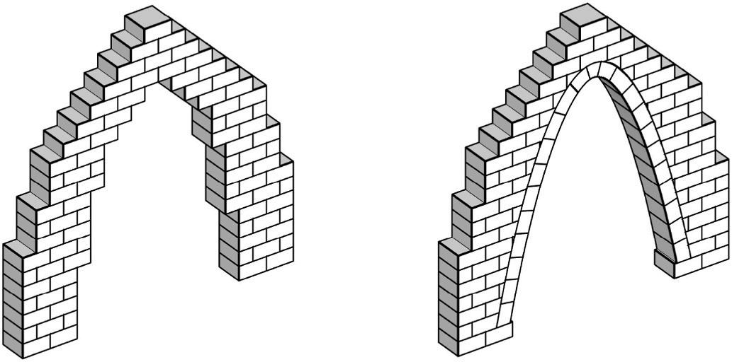
A corbel arch is constructed by offsetting successive horizontal courses of blocks from the springline of the wall up to the apex of the archway. As shown in Fig. 1, a corbel arch is constructed by horizontally laying blocks and bridging the last gap with a flat block, while a true arch consists of wedge-shaped voussoirs held together by a central keystone. Though, when compared with true arching, corbeling is less efficient at transforming the structure’s tensile stresses caused by its own weight into compressive stresses, it still has the advantage of using only one type of material when compared with the post and lintel design (i.e., a structural system with straight walls, vertical columns, and horizontal beams). Further, it is almost infeasible to have a few types of interlocking blocks to form a dome-shaped masonry structure at a building scale. Since the blocks in a corbelled structure are always placed horizontally, it has advantages in minimizing block types while maintaining the interlocking features and flexibility in the dome geometry. Moreover, with proper design, a corbel arch can be stable during the whole assembly process, while “true” arches are stable only after placing the final keystone. Therefore, though most existing research selects the true arching technique over corbeling, the corbel vault concept is adopted in the proposed design in this research since reducing the number of block geometries is essential for low-resource settings.
Masonry is one of the most significant construction techniques in buildings and is widely adopted in developing countries and remote areas due to its constructability, local availability, and low-cost features. However, unlike other widely used structural materials such as steel or reinforced concrete, the stability of unreinforced masonry (URM) relies primarily on the geometry of the structure rather than on material strength (Heyman, 2019). Due to the negligible capacity in tension of masonry, a layer of adhesive material (e.g., mortar) is filled between the blocks during the construction process. In the past few decades, the high
demands for fast, cost-effective, and sustainable construction led to changes in the conventional masonry system, which include surface bond masonry, fiber-reinforced polymer wrapping masonry, grouted masonry, and interlocking masonry (Al-Fakih et al., 2018). Compared with traditional blocks, interlocking blocks are connected by interlocking joints (protrusions and grooves), eliminating the use of mortar joints and thus improving sustainability. In addition, the dry stack and interlocking feature can speed up the construction process for less-skilled workers or self-builders, targeting low-resource settings.
The state-of-the-art research on interlocking blocks focuses on improving the interlocking design and mechanism mostly for planar assembly and curved assembly with simple geometries (Weizmann et al., 2016a, 2016b; Ma et al., 2020; Zhou et al., 2020b; Dyskin et al., 2019; Fallacara et al., 2019; Sass, 2008) or utilizing new materials but with complex interlocking features (Wilton et al., 2019). This is because, though an interlocking joint from a traditional interlocking block can guide the workers to align and orientate the blocks, it is at the same time constraining the flexibility of assembly and thus limiting the diversity of the structure. Hence, this research intends to lift this barrier and extend the utilization of interlocking blocks to the roof system so that there is only one type of material using one construction technique for the main structural systems (i.e., wall and roof). This is beneficial in simplifying the process and essential for reducing costs, especially considering the limited material and transportation resources in low-income countries or remote areas.
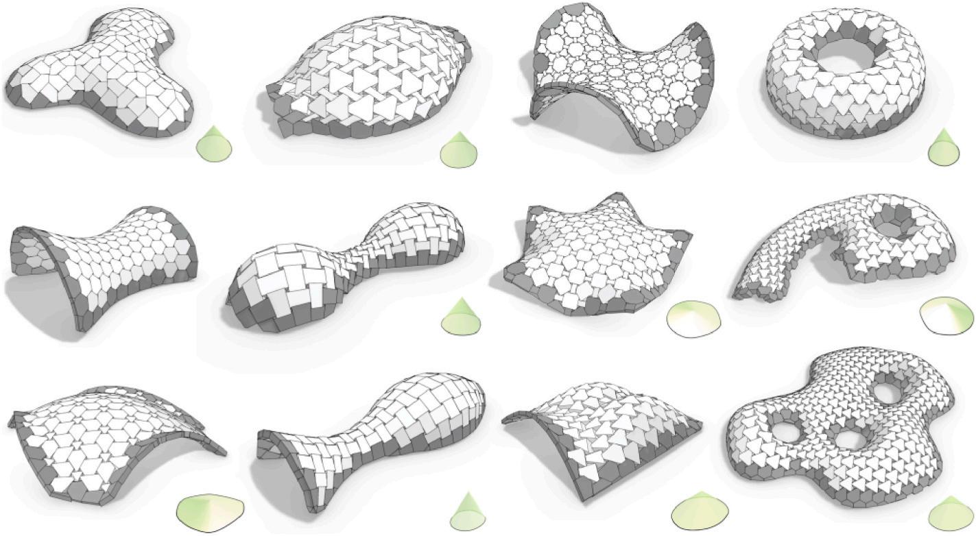
New advances have been made to assemble irregular and free-form vaults with interlocking blocks, as shown in Fig. 2 (Wang et al., 2019). These free-form designs require a large number of unique blocks, leading to either 3D printing every block or producing a high volume of molds, each with low utilization. Moreover, since the block geometries are customized for the prescribed shape and size, dwelling designs are not scalable with the same set of block geometries. Hence, this technique is not suitable for building design in low-resource settings. Generally, it is still challenging to assemble a curved structure with a few interlocking block types, except for geometries with regular curvatures and sections, e.g., a cylinder or semi-sphere.
To minimize the total number of block types, i.e. geometry, but still maintain the scalability of the structure, this research carefully examines two intertwined aspects simultaneously: the design of the interlocking block system and the design of the entire structure, i.e. dwelling.
The stability of an unreinforced masonry structure is essential and is thus verified in this research. The stability is evaluated by modeling the
blocks as rigid elements, computing force resultants on interfaces, and checking if tensile forces are required on these interfaces to maintain stability (Whiting et al., 2009, 2012). The algorithm from Whiting et al. (2009), with modifications, is applied and formulates the stability problem as a linear program, as shown in the equation below.
Bfr f ≤ 0
f i n = f i+ n f i n
f i n , f i+ n ≥ 0
where Beq is an equilibrium matrix that records the affiliated vertices of the contacting interfaces (with directional information) of each building object; f i n is the normal force resultant at vertex i that is not restricted in sign when defined by a difference between two non-negative variables f i n and f i+ n ; w is a vector composed of the weight of each building object; The first constraint in Eq. (1) is the equilibrium constraint that projects and sums up f i n for each axis as well as their introduced moments for each axis, such that both the force equilibrium and the moment equilibrium are maintained for each building object subject to external forces (e.g., self-weight) and moments, if any. Bfr is a matrix that maps f to the difference between the in-plane forces and the maximum friction at each vertex, defined by the normal force f i n and the corresponding coefficient of static friction of the contacting interfaces of each object (with a typical value of 0.7 selected in this paper). Therefore, the second constraint in Eq. (1) is a sparse linear system of inequalities that resembles the friction constraints over the entire assemblage of blocks in this structure. This formulation penalizes the tensile forces. If and only if the objective value is zero, will this structure, without inter-block adhesives, be statically stable.
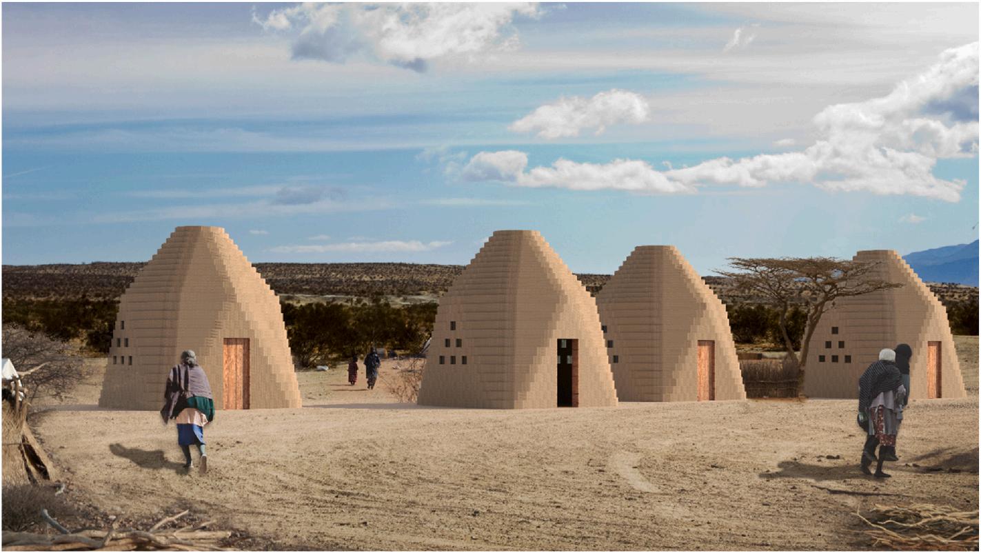
The example context used in this work is Morocco, which has earthen architecture as part of the history and identity of its society (Gil-Piqueras and Pablo, 2021). The vernacular earthen buildings arise from the environment itself and are endowed with a great adaption capacity, both to the climate and to the territory (Fernandes et al., 2019; Arrigoni et al.,
2017). Though being an example and model for contemporary architecture, this traditional heritage has deteriorated due to abandonment (Gil-Piqueras and Pablo, 2021) and is currently out of favor. With the use of modern technology to design earthen architecture, we aim to modernize it and make it more appealing.
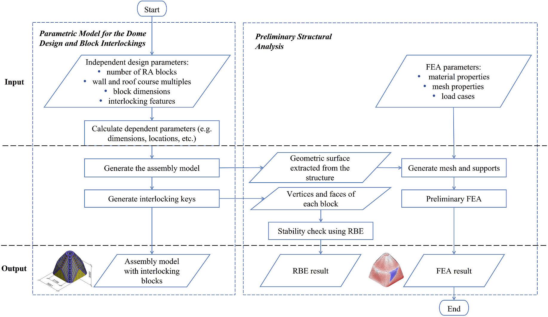
The template design is a single-story dwelling consisting of a few interlocking block types. The rationale of the design is to integrate the roof and walls into one system that enables the use of one construction material and technique, with satisfactory architectural layout and structural efficiency. A novel interlocking design for the blocks consisting of multiple interlocking features, or joints, is introduced in Section 3.1, allowing for different stacking mechanisms. This interlocking design enables a significantly reduced number of interlocking block types to fit the geometry at different scales, as presented in Section 3.2, which smoothly transitions from a squared base footprint, for the convenience of architectural layout, to a circular roof zone, for efficient arching. The detailed design of the interlocking joints of the dimensions of the blocks, and of the overall geometry are intertwined, with calculation and derivation presented in Section 3.3. Both a stability check and preliminary FEA at the macroscale are carried out and introduced in Section 3.4 A flowchart of the process for the parametric model and structural analysis is shown in Fig. 3
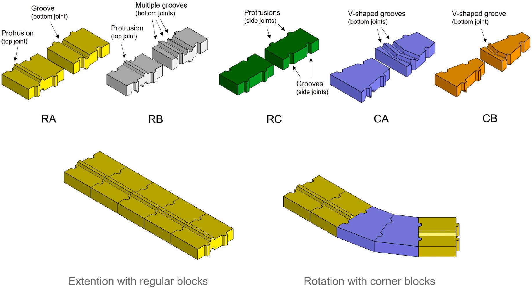
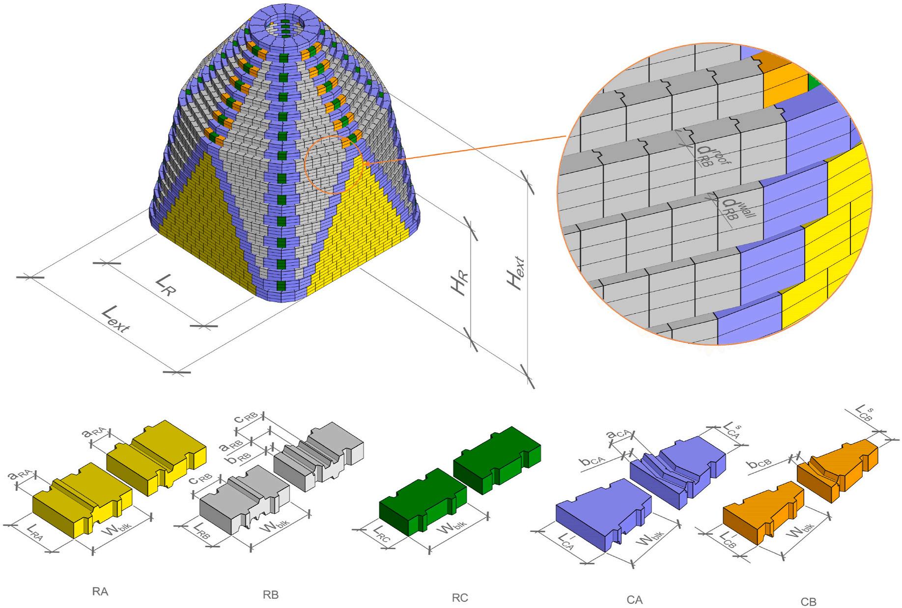
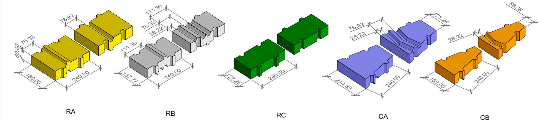
The proposed design consists of five types of block geometries, including three regular blocks and two corner blocks, as shown in Fig. 4 The regular blocks are named RA (used for straight walls), RB (used for inclined walls and roof), and RC (used to extend corners), while the two corner blocks are named CA (with a larger length), and CB (with a smaller length). Fig. 4 shows different interlocking features (grooves and protrusions) among these five block types, which are correlated to the design of the dwelling and will be explained in detail in Section 3.1.2 For masonry structures, a “course” is a layer of blocks running
horizontally in a wall (Harris, 2006). The regular blocks are cuboidal and thus only extend the length of the course, while the corner blocks are trapezoidal and can change the direction of the course and thus define the shape of the course, as shown in Fig. 4 This proposed design can minimize the number of different block types otherwise it would require at least one block type for each course in the corbelled dome, due to the different radius and curvature of each course.
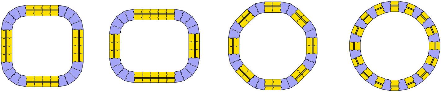
To form a full cycle in one course, 360◦ should be divisible by the included angle θ between two legs of the trapezoid on the corner block. For example, the proposed design in this research sets θ = 22 5◦ , so 16 corner blocks are needed to form a full circle. Several combination examples within one course are shown in Fig. 5 One course with sixteen corner blocks enables various shapes such as a square, i.e. with four equal-length sides and combining every four corner blocks, a rectangle, i.e. different lengths for two pairs of sides and combining every four corner blocks, an octagon, i.e. with eight equal-length sides and combining every two corner blocks, and a hexadecagon, i.e. with four sixteen sides and separated corner blocks. Though the template design proposed in this research partitions the course with sixteen corner blocks using θ = 22 5◦ , the partition is modifiable. For example, when partitioned with twelve corner blocks with θ = 30◦ , a course can form the geometry of a triangle or hexagon, etc.
To enable a mortarless and stable assembly during construction, interlocking features, including side and top-bottom interlocking joints, are embedded into the block design, as shown in Fig. 4 Instead of the mortise and tenon joints that are widely applied in interlocking masonry blocks, this research applies two-way joints that enable motions of associated blocks in both normal and tangential directions to allow for more flexibility in the placement of each block geometry. For the side interlocking joints, as shown in Fig. 4, all the block types have the same joint layout since the blocks are placed horizontally aligned within one course. The proposed design implements an example design of two interlocking joints distributed along the side surfaces, which can be flexibly adjusted if needed.
On the other hand, since the proposed design is based on the corbelling technique, the blocks should be able to be stacked vertically
aligned, with tangential offsets (in terms of the course), with radial offsets, or with a combination of both. Thus, to enable multiple stacking functions of one block type and keep minimal block types, this research proposes integrating multiple, parallel grooves on the bottom surfaces,
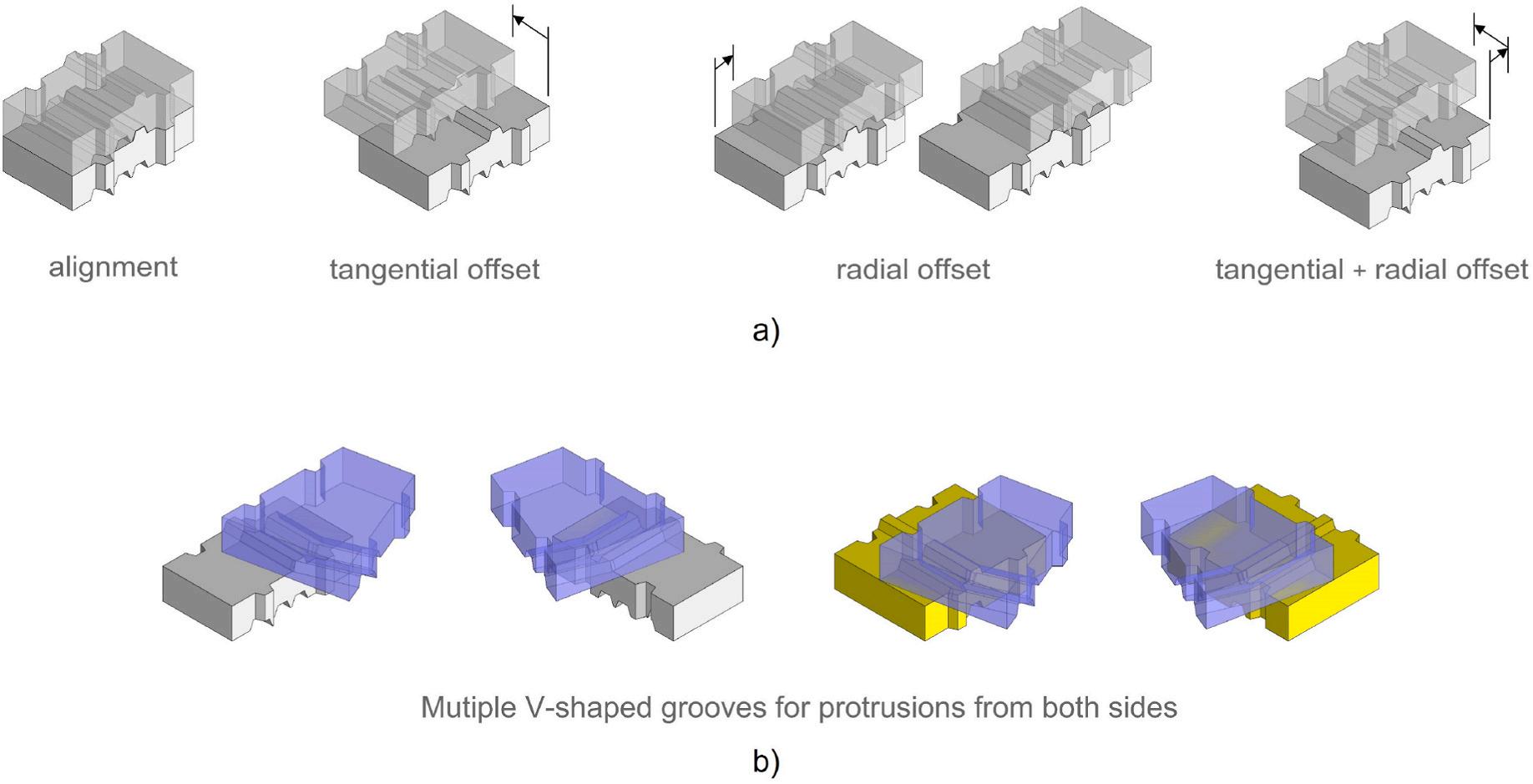
as shown in Fig. 6 This design allows the blocks to be stacked aligned, with tangential offsets, with radial offsets, or both, based on the relative distance from the protrusions on the top surfaces, as shown in Fig. 6a. However, the proposed design does not include a protrusion for block
RC and for both corner blocks CA and CB. This simplifies the block joints since having protrusions on the corner blocks would add two more grooves to themselves and to the regular block RB. Making the interlocking joints as simple as possible keeps the process accessible for lower-skill or first-time builders. It also improves the structural integrity of the whole block since an increased number of two-way grooves may create thin, fragile parts, especially for brittle materials such as raw earth. The corner blocks (CA and CB) are implemented with V-shaped grooves to fit the protrusions of regular blocks in the course below coming from both sides, as shown in Fig. 6b.
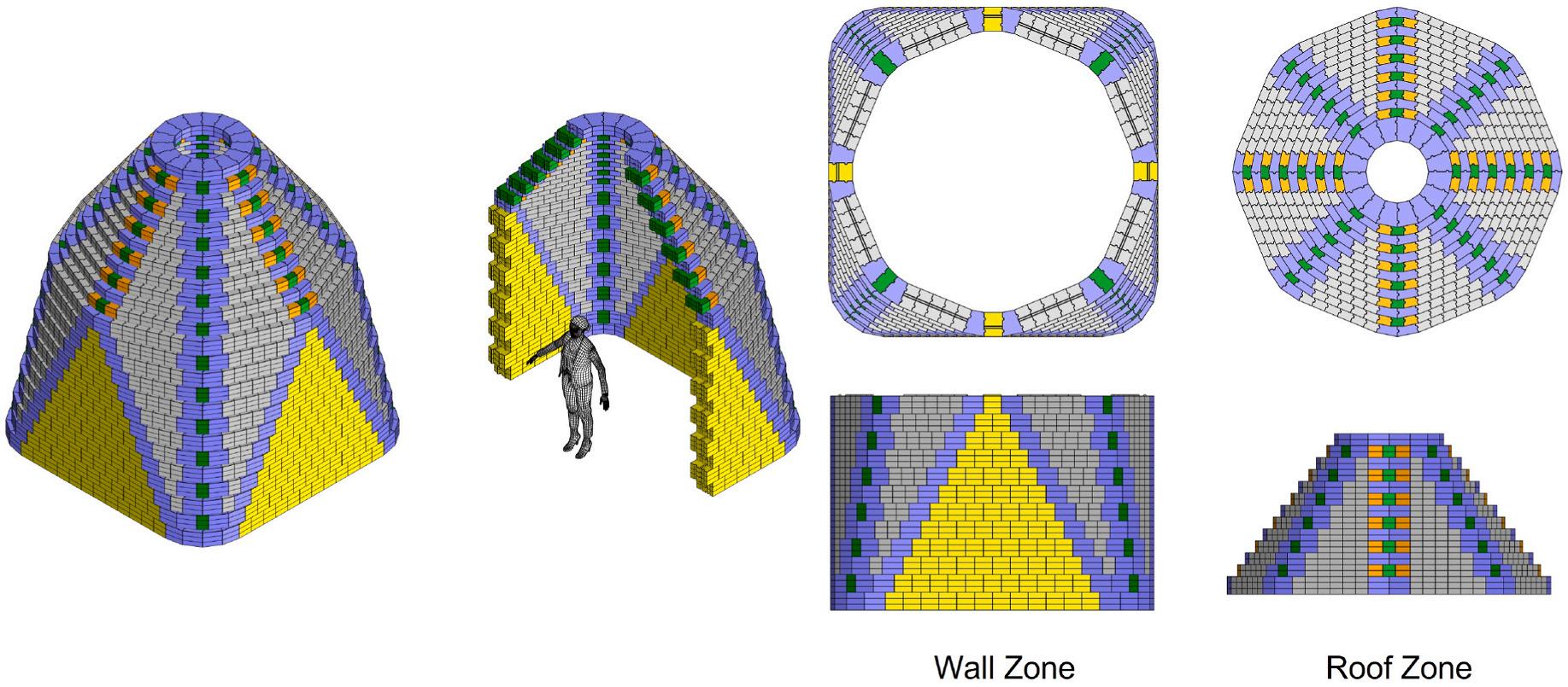
The template design, as shown in Fig. 7, is a hybrid of a dome and a conventional room, transitioning from a square base footprint to a circular roof zone, optimized for a practical architectural layout and structural efficiency. When compared with other low-rise dwellings with square or rectangular footprints and roof sections, e.g., the Cork House (Wilton et al., 2019), the circular courses for the roof in the proposed design can improve structural integrity. Compared with other dome-shaped structures, e.g., the Tecla dwelling (WASP, 2022), the squared base footprint enables the residents to easily place conventional door and window frames and furniture. Further, the straight walls enable dwellings of different scales to be combined as multi-room dwellings, which expands the potential of the proposed design as a modular component of large-scale dwellings, as described in Section 3.2.2
Duplicated courses can be implemented, which double or triple each unique course vertically in order to adjust the overall geometry in terms of height or slope. The example design shown in Fig. 7 demonstrates a triple-course wall zone and a double-course roof zone.
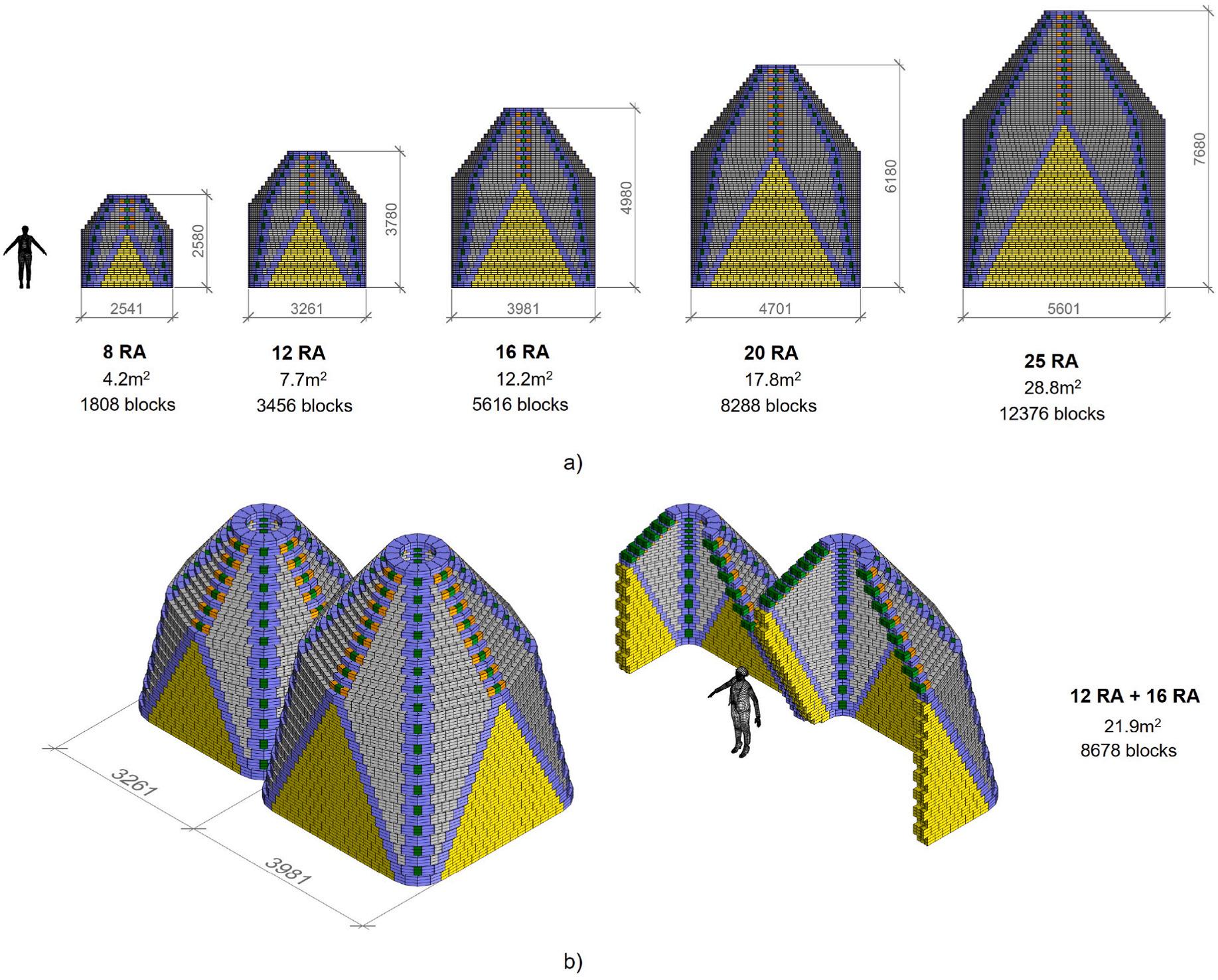
With the same set of block geometries, the design is scalable by adjusting the number of RA blocks in the base course, as shown in Fig. 8a. The resolution is at the scale of one interlocking block. Thus, theoretically, by changing the dimensions of the blocks as well as changing the layout (i.e. number of blocks) for the base course, the design can be scaled. Detailed designs at different scales are illustrated in Section 4
However, it is noteworthy that the scale can significantly influence the structural performance of the dwelling. For a self-sustained dome, excessively expanding the span and partitioning the space to create
rooms can be structurally detrimental. This research addresses this issue by providing another efficient option: instead of scaling up one dome, it can be more efficient and structurally favorable to utilize the straight walls and attach several domes to form a complex, as mentioned in Section 3.2.1 Fig. 8b illustrates this concept by using the same set of block geometries to form multi-room dwellings with a combination of domes of different dimensions.
To minimize the total number of block types, as described in Section 2.3, but still maintain the scalability of the structure, or dwelling, it is essential to carefully examine both the design of the interlocking system and the design of the entire structure since they are interdependent. Without rigorous analysis and calculation, it is challenging to fit interlocking blocks, with a few block geometries, into the target geometry without any gaps or overlaps. Thus, this Section provides the formulas for the dimensions of the dwelling and of all the blocks in the wall zone and the roof zone, as well as the detailed specification for the interlocking details. All the formulas for the top-bottom interlocking features are derived using the trigonometric relationship. This analysis is the basis for the parametric, generative design model that automatically generates the Computer-Aided-Design (CAD) model of feasible designs, including block geometry, layout, and interlocking details.
The wall zone starts from a square footprint and gradually transitions to an octagon as the courses build up. The rough length of each side of the square, as well as the height of the wall zone, are determined by the number of RA blocks at the base course, as shown in Fig. 9 and in the following equations:
where LR and HR are the base length and the height of each wall zone segment, Nbase RA is the number of RA blocks at the base course, while LRA is the length of the RA blocks. Hblk is the height of all block types and nwall H is the duplication number of the course in the wall zone. Besides, the widths of all the blocks are also set to the same value Wblk such that they can be attached and aligned within one course. The exact values of Hblk and Wblk should be determined by the user and constrained by the fabrication process.
For every course from the base course to the top course in this wall zone, one RA block is removed from each side of the course. From each vertex of the square at the base course, two wall facets are developed, where one more RB block is added for each facet in every course. More specifically, the transition starts from a square section at the base course. A twelve-sided polygon gradually develops from the second course from the base until it converges into an octagon at the top course of the wall zone.
The proposed design specifies the length of the RA block LRA as input, and the length of the RB block LRB can be derived and expressed as:
LRB = sin 45◦ sin 112 5◦ LRA (4)
After analyzing the trigonometric relations, the radial offset of RB between adjacent courses in the wall zone and in the roof zone are derived and expressed as:
dwall RB = sin 22 5◦ 2 LRA (5)
droof RB = cot 22 5◦ 4 LRB (6)
where dwall RB and droof RB are the radial offset of RB between adjacent courses in the wall zone and in the roof zone, respectively. It is noteworthy that since block RA is only placed in the straight wall segment in the wall zone, it has no radial offset and thus only needs one groove and one protrusion to be stacked aligned.
The trapezoidal corner blocks CA and CB are implemented to fill the gap in each course. The reason for introducing different lengths of corner blocks is to remove aligned seams in the roof area. Only one of the dimensional parameters needs to be specified as input since the lengths of the longer bases of these two blocks follow:
LlCA = LlCB + cos 56 25◦ + sin 56 25◦ × tan 11 25◦ 4 sin 67 5◦ × tan 22 5 LRB (7)
where LlCA and LlCB are the lengths of the longer bases of corner block CA and CB, respectively. The lengths of the shorter bases can be expressed as:
LsCA = LlCA 2 cos 78.75◦ Wblk (8)
LsCB = LlCB 2 cos 78 75◦ Wblk (9)
where LsCA and LsCB are the lengths of the shorter bases of corner block CA and CB, respectively. Since the RC block is used to extend the corner block, its length LRC is expressed as:
LRC = 2( LlCA LlCB )cos 11 25◦ (10)
Thus, the envelope of this structure, as shown in Fig. 9, are expressed as:
Lext = LR + 2LlCA (cos 11 25◦ + cos 33 75◦ + cos 56 25◦ + cos 78 75◦ ) (11)
Hext = ( N base RA ( n wall H + nroof H ) + n wall H )Hblk (12)
where Lext and Hext are the external length and the external height of the structure, respectively. nroof H is the multiplier in the roof zone.
As introduced in Section 3.1.2, all the block types have two interlocking protrusions and grooves on the sides at the same locations. The differences reside in the top and bottom interlocking features: only the regular blocks RA and RB have a protrusion on the top surface and groove(s) on the bottom surface, while the corner blocks CA and CB only have groove(s) on the bottom surface and no top-bottom interlocking joints. Block RC has no top or bottom interlockings since it is always placed on top of block CA or block RC, or below block CA. The layout of the interlocking grooves is closely related to the radial offsets.
Since the top and bottom interlocking locations are correlated, the interlocking layout of each block type needs to be designed in a sequence such that the number of interlocking joints can be minimized. The sequenced design procedures are 1) specify the location for the interlocking joints of block RA, which is denoted by aRA ; 2) the location for the first v-shaped groove of block CA, denoted by aCA , equals aRA ; 3) the location for the second v-shaped groove of block CA, denoted by bCA , is derived based on aCA and the radial offsets of block RB droof RB and dwall RB ; 4) the location for the v-shaped groove of block CB, denoted by bCB , equals bCA ; 5) the location for the protrusion as well as the first groove of block RB, denoted by cRB and is used for stacking aligned, is derived based on aCA and the radial offset in the wall zone dwall RB ; 6) the location for the second groove of block RB, denoted by aRB is derived based on the first protrusion location aRB and the radial offset in the wall zone dwall RB ; 7) the location for the third groove of block RB, denoted by bRB , is derived based on the first protrusion location cRB and the radial offset in the roof zone droof RB . The dimensions are illustrated in Fig. 9, and the detailed expressions are shown in the following equations:
After simplification, there are three distinct values left: 1) aCA = aRA = aRB ; 2) cRB = aCA + dwall RB ; 3) bCA = bCB = bRB = aCA droof RB + dwall RB . Thus, only one parameter needs to be predefined and the other parameters can be calculated with Eq. (13) to Eq. (18). The constraint is that all the parameters need to be feasible (i.e. larger than a defined positive value).
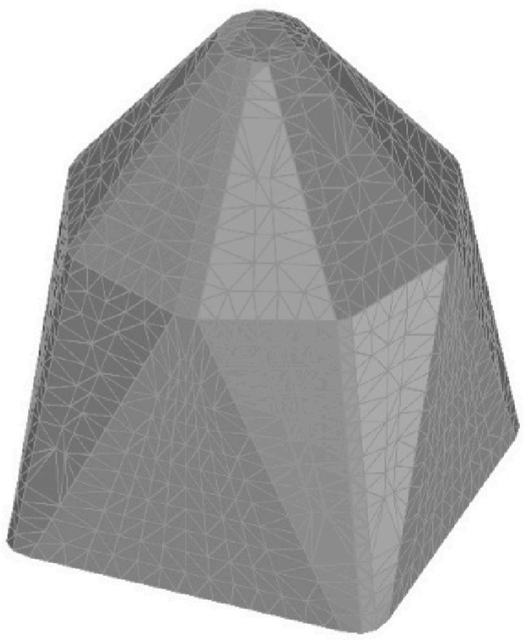
The parametric model is evaluated by two types of structural analysis: the stability check using Rigid Body Equilibrium (Whiting et al., 2009), as discussed in Section 2.4, and a preliminary Finite Element Analysis (FEA) on a macroscale thin shell model (Heyman, 1966), as shown in Fig. 10. The thin shell model is extracted from the geometry of the structure, whose thickness in the examples given in this paper equals the width of the block. The thin shell is meshed using triangular elements with a typical size of 0.2 m, with mixed formulation (u/p). Karamba3D® in Grasshopper is used for FEA. The support points are all the points of height 0, and are fixed in all degrees of freedom.
For a specific site, the structure’s purpose, dimensions and materials of the blocks determine the loading that must be considered. Under
strength or ultimate limit state (ULS) design, structures are designed to resist the most critical effects resulting from various combinations of factored loads. While serviceability design has several common parameters, including deflection, vibration, slenderness, and clearance, this paper examines the structural performance under ULS as an example since the proposed design is intended as a one-story dwelling where ULS design is dominant.
The material selected for the case studies in Section 4 is compressed raw earth with material properties shown in Table 1
The load cases prescribed as an example for the case studies include self-weight as dead load (D), and 1 kPa wind load (W), applied laterally. The load combinations under the ULS design are specified as follows (EN 1990, 2002):
ULS1: 1.35 D + 1.5 W
ULS2: 0.9 D + 1.5 W
Note that the safety factor for the dead load (D) in ULS2 is modified from 1.0 in the code to 0.9 for conservativeness.
This Section further demonstrates the range of possible designs encoded in the parametric, template design to generate various
dimensions and dwellings, along with the preliminary FEA results. Section 4.1 introduces the dimensions of the interlocking blocks selected. Section 4.2 illustrates single-room dwellings at various scales and the approach to reach a prescribed dimension in different scenarios. Finally, one multi-room dwelling example is shown in Section 4.3 All examples illustrated and discussed in this Section use the same set of blocks prescribed in Section 4.1
4.1. Block dimensions used for case studies
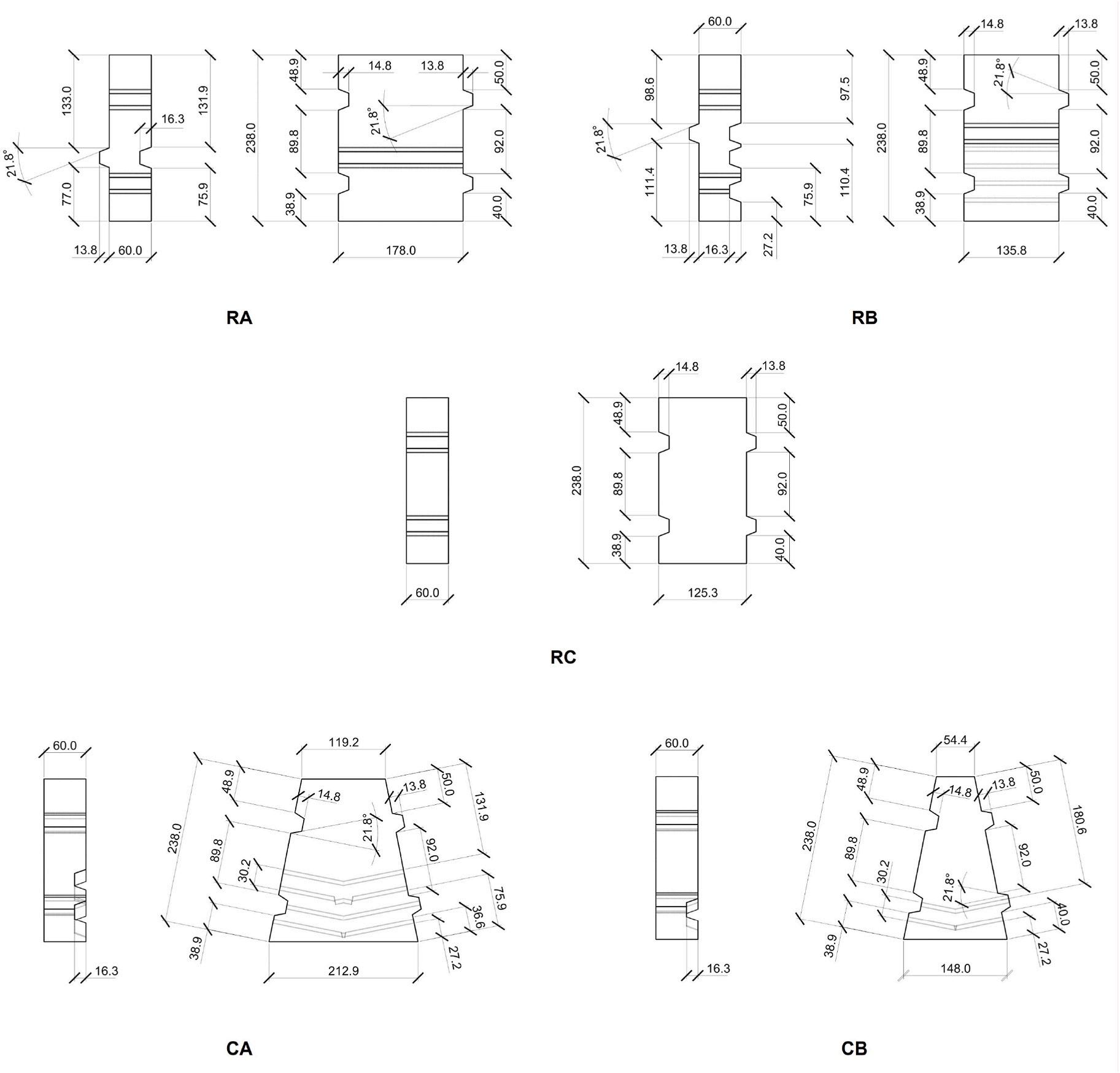
To explore and demonstrate the possibilities with only one set of block geometries, the case used in this Section stems from the same set of block geometries, with dimensions shown in Fig. 11 As discussed in Section 3.3.2, only one independent parameter is specified, i.e. aRA = 76 92, and other dimensions for the top-bottom interlocking joints are calculated with Eq. (13) to Eq. (18). Note that these calculated dimensions does not include any tolerances. The tolerance should be specified based on the fabrication process and materials. For a feasible assembly, an example tolerance of 1 mm is implemented in the dimensions, as shown in Appendix A.
In this Section, single-room dwellings with various scales using the same set of block geometries are presented. The first examples, as shown in Fig. 8, demonstrate dwellings with triple-course wall zones and double-course roof zones. Fig. 12 shows the 3D-printed prototype of a 12RA dwelling with triple-course wall zones and double-course roof zones, with potential windows and door designs. The location and geometry of the openings are not restricted to the example design in Fig. 11. Other variations or customized designs are possible according to different needs and contexts. An example of rectangular doors and small ventilation openings is shown in Fig. 13 The ventilation openings in this example are integrated by removing separated stacks of aligned blocks in the wall zone.
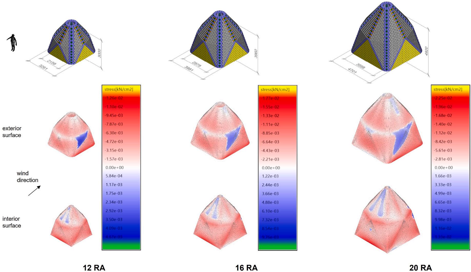
The properties of the dwellings shown in Fig. 8, including the number of blocks, envelope, useable area, and maximum stresses, are listed in Table 2 The corresponding FEA results (Von Mises) of the case studies under ULS are illustrated in Fig. 14 Since ULS1 is dominating, as shown in Table 2, the FEA result in Fig. 14 only includes ULS1. The two surfaces of each scale are the interior surface and the exterior surface.
The result of the FE model shows a stable dome structure that is predominantly in pure compression with localized areas of lateral flexural stress. There are low levels of tensile hoop stresses in the model around the wall and roof interface due to the modeling of the continuous FE mesh. This hoop stress, in reality, will form due to the inability of the earth blocks to transfer load through the joints. This is a common issue with modeling domes in FE so further analysis using a series of arches, splitting the dome into segments, is required to fully justify these interfaces of blocks.
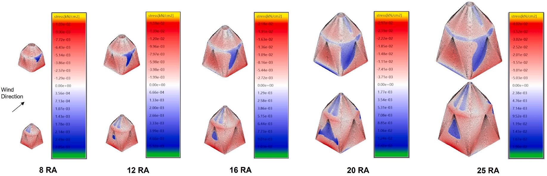
This research further explores the potential of the same set of block geometries and reduces the height of the dwelling by adjusting the wall zones to be double-course, i.e. two layers of blocks (vertically) in each course, and keeping the roof zones double-course. The selected example cases and their corresponding FEA plots and properties are shown in Fig. 15 and Table 3 Different from the triple-course wall zone design in Fig. 14 and Table 2, the 8RA version with a double-course wall zone is not considered in this case. This is because a double-course 8RA version results in an impractical wall zone height (HR ) of 960 mm, which makes it challenging to install a door or align any furniture to the wall. Moreover, the 25RA dwelling with a double-course wall zone is also excluded for simplicity. Similarly to Fig. 14, only FEA results under ULS1 are shown in Fig. 15
Similar to the previous examples in Fig. 14 and Table 2, the result of the FE model shows a stable dome structure that is predominantly in pure compression with localized areas of lateral flexural stress. With the
same footprint, the stresses of a dome in Table 3 are smaller than their corresponding stresses in Table 2 This is expected since the overall height of the dwelling is reduced.
As can be observed in Table 3, the dwelling height (Hext ) can exceed 4.9 m for a footprint of 17.8 m2, which can be unnecessary. To further reduce the dwelling height and save construction material, a singlecourse roof can be adopted in part of the roof zone, which follows the aforementioned rationale and thus is not extensively illustrated in this Section. A multi-room dwelling example with a single-course roof and double-course walls is shown in Section 4.3.
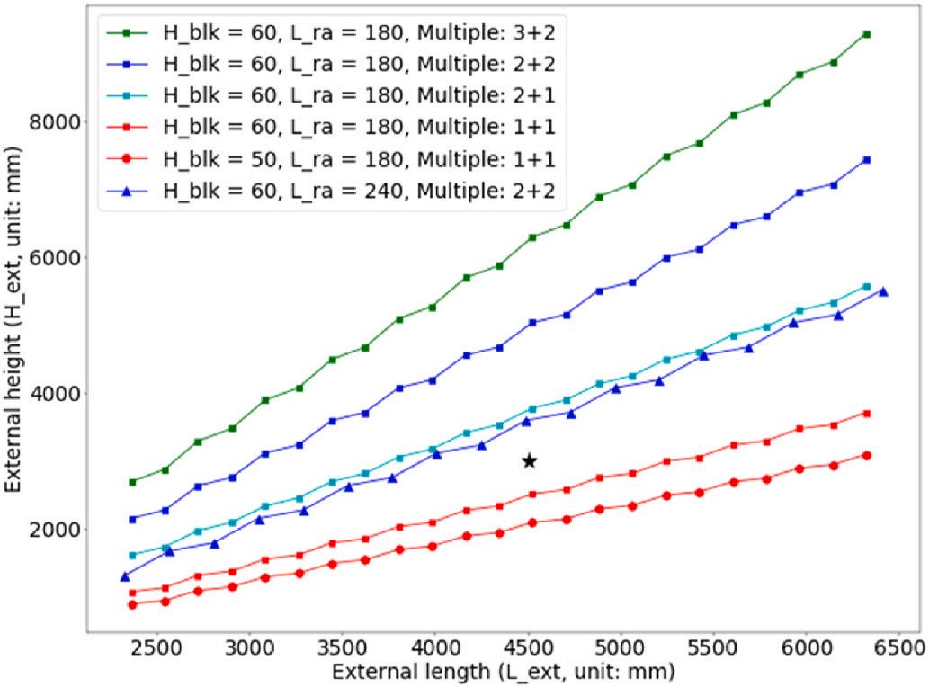
With the same set of block geometries, the scales achieved by different single-room dwellings are exhibited in Fig. 16 Generally, any intermediate scale with prescribed dimensions, including wall zone height HR , can be achieved by one or a combination of the following operations: 1) adjusting the number of RA blocks at the base course (Nbase RA ); 2) adjusting the course multiplier of the wall zone and the roof zone, or using a mixture of the multipliers (e.g. triple-course in the first half of the wall zone and double-course in the second half of the wall zone); 3) adjusting the length of the RA block (LRA ); 4) adjusting the block height (Hblk ).
The colored lines with small dot markers show the external lengths (Lext ) and heights (Hext ) achieved by using the same set of block geometries introduced in Section 4.1, but with different multiples of courses in the wall zone and the roof zone (e.g. Multiple: 3 + 2 denotes a triplecourse wall zone and a double-course roof zone). The red polyline with large dot markers presents the dimensions (i.e. Lext and Hext ) achieved by adjusting the block height (HR ) from 60 mm to 50 mm, while keeping other parameters the same as the setup in Section 4. The blue polyline with triangle markers corresponds to dimensions achieved by adjusting the length of block RA (LRA ) from 180 mm to 240 mm, while keeping other parameters the same as the setup in Section 4.1 It can be observed that the relationship between the external length and height is linear, in alignment with Eq (11) and Eq (12)
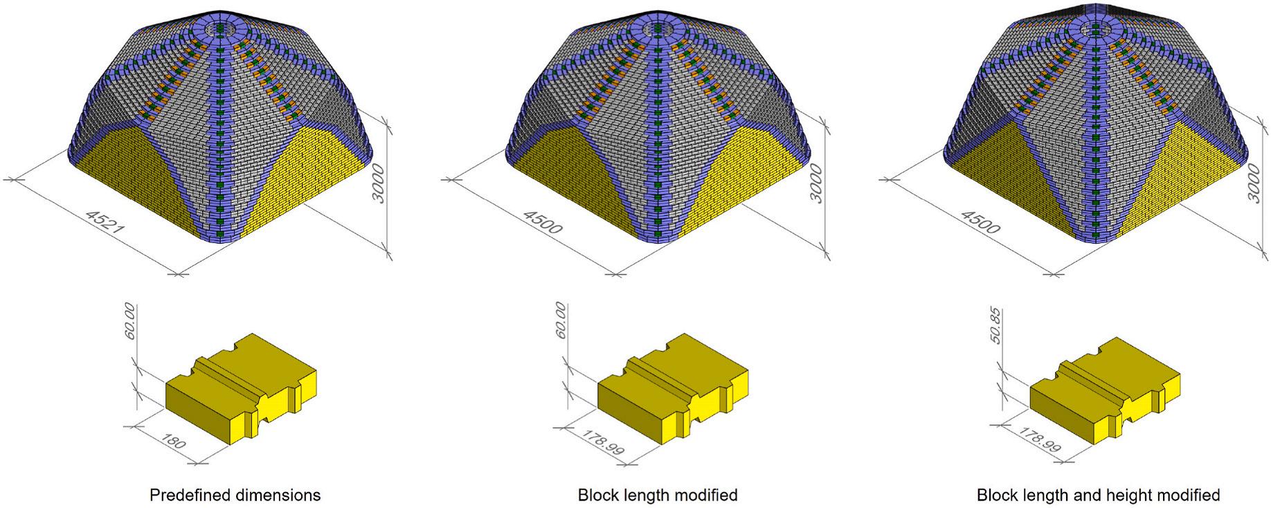
Fig. 16 does not extensively enumerate all the possible combinations but illustrates some example cases. As discussed in Section 3.2.2, given a set of block geometries, the dimension increment of the dwelling is discrete, with the resolution at the scale of one interlocking block. However, prescribed dwelling dimensions can be approximated with certain techniques described above. For example, the black star marker shown in Fig. 16 is a dimension selected, with 4500 mm external length
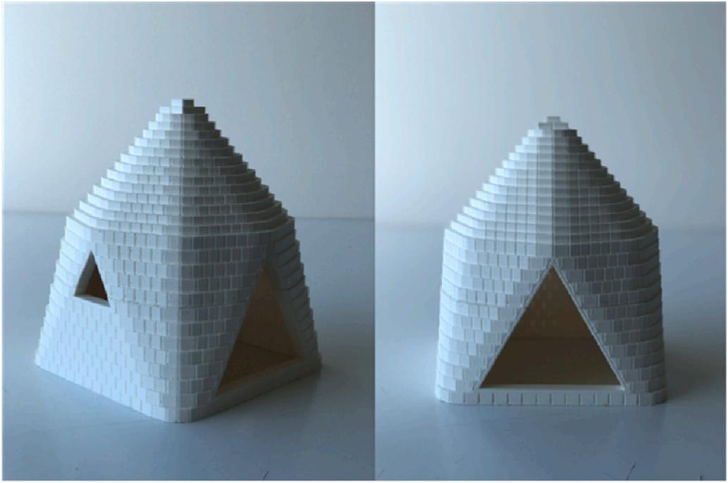
Table 2
Properties of different scales with triple-course walls and double-course roofs.
and 3000 mm external height, to represent a prescribed design. Generally, there are two different approaches to configure the dwelling of this specified dimension.
1) If the blocks are predefined, i.e. as in the set from Section 4.1, the dwelling dimension can be reached by a 19RA version with the first eleven courses in the wall zone doubled and the rest single-course,
which yields an external length of 4521 mm and 3000 mm external height, as shown in the first design in Fig. 17 This approach is advantageous when the blocks are already fabricated or if a small number of predefined block geometries are preferred when configuring dwellings of various dimensions.
2) If the design of blocks is not fixed, the target dwelling dimension can be further reached by setting the length of the RA block (LRA ) to be
and double-course roofs.
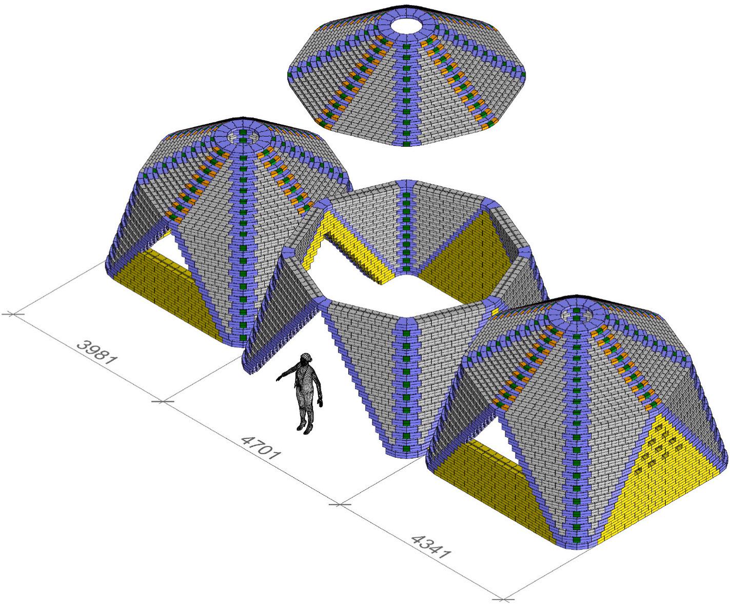
As explained in Section 3.2, the square footprint allows for a customized house with multi-rooms, as well as futureproofing the need to expand the dwelling by adding more rooms. Fig. 18 illustrates a design of a multi-room house with double-course walls and a singlecourse roof. This example house consists of a 16RA dome, a 20RA dome and an 18RA dome, from left to right, with a footprint area of 47.9 m2. Three straight walls of one room are removed for door openings, while several segments of walls of the two rooms are removed for window installations. Alternative designs are also possible in addition to the design of openings shown in this example, as long as structural integrity is checked. In Fig. 19, a design of a dwelling with multiple rooms and atriums is demonstrated using 3D-printed models.
In this research, a novel template design for single-story interlocking masonry dwellings is developed. The interlocking nature of the blocks not only enables dry-stacking and enhances structural integrity but also acts as a guide to locate and orientate the blocks. Thus, specialist construction knowledge and training are minimized, enabling access by less-skilled and first-time builders. Using the same set of block geometries, a dome-shaped corbelled dwelling is designed with transitioning zones that efficiently combine the lateral and vertical systems with the same building technique. In the case of constructing the design with Compressed Earth Blocks (CEB), this can result in significant cost reduction since currently the roof is often constructed of a different material and corresponds to 50% of the cost (UN-HABITAT, 2019). The square footprint allows for a customized dwelling to be designed with multiple rooms, as well as enabling straightforward expansion to the dwelling by adding more rooms.
178.99 mm, and either keeping other parameters the same as 1) or redesigning the height of blocks as shown in the second design in Fig. 17, and/or then modifying the multiples of courses in the wall zone and roof zone. For example, set the block height (HR ) to 50.85 mm and the length of the RA block (LRA ) to be 178.99 mm, as shown in the last design in Fig. 17
The template design is enabled by the creation of an automated parametric model that calculates the transitions of the dome geometry, dimensions and locations of each block, interlocking block features, and generates the CAD model for a design automatically, which would be infeasible to model manually. This also makes it scalable. It integrates the design modeling and preliminary structural analysis into one design tool, with the 3D model and the FE results shown simultaneously. This creates a decision support method for builders, especially self-builders or inexperienced builders, to explore and select from various design alternatives.
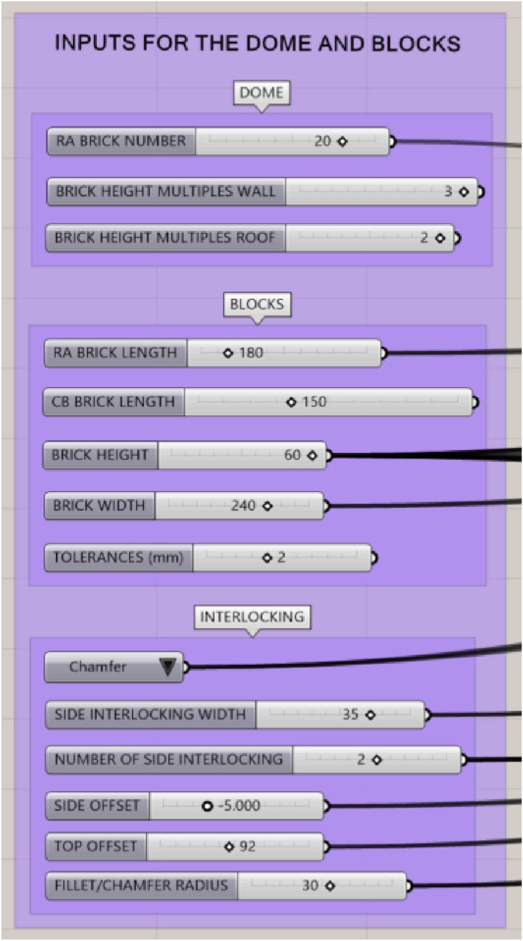
The design tool is written as a Grasshopper® 3D script for Rhinoceros 3D where the input parameters for the dome and blocks are shown in Fig. 20 The steps of the design of the blocks and dome, as shown in Fig. 3, include: 1) Specify the input parameters for the dome, i.e. the
number of RA blocks in the base course, wall and roof course multiples, block dimensions, if not fixed, interlocking parameters, e.g. aRA , and the FEA parameters; the external length and height are calculated according to equations (11) and (12) 2) Automatically generate the CAD model and carry out the structural analysis, as illustrated in Fig. 3; 3) Check the performance such as manufacturability and structural integrity and adjust the input parameters if needed. When a set of block types are finalized, which can be defined differently to those given here both in geometry and number of types, alternative scale designs can be automatically generated by adjusting the three input parameters for the dome. So far, five different block sets, each with a few block types, have been tested with the model, for example the one given here (Zhang et al., 2021). The space of designs is vast and only possible to explore using computational design methods. The future work for the parametric
model involves developing a user-friendly interface and enabling more functionality, such as customizable patterns (Knight and Sass, 2010). The case studies presented in Section 4 illustrate the scalability of the template design. The same set of interlocking block geometries is used to create larger designs by adding more blocks in a single-room dwelling and by configuring a complex with multiple connected smaller dwellings. The footprint area of a dwelling is almost linear to the total number of blocks in this dwelling. By varying the multiplier of courses, different slopes can be achieved in the wall and roof zone to reach specific needs architecturally and structurally. More specifically, a larger dwelling height results in a steeper slope, which can influence tensile and compressive stresses. For example, with the same footprint (16RA, Lext = 3981 mm) and double-course roof zone, a triple-course wall zone yields a dwelling height Hext = 4980 mm and maximum tensile stress of 0.103 MPa (under ULS1), while a double-course wall zone yields a dwelling height Hext = 3960 mm and maximum tensile stress of 0.0976 MPa (under ULS1). The result also demonstrates that any dwelling with user-defined dimensions, if structurally feasible, can be achieved by a series of modifications without compromising the simplicity of the building components, i.e. number of block geometries.
Compared with the existing alternatives, the proposed template design and parametric model demonstrate advantages from multiple perspectives: 1) Through the parametric model a design can be generated with a seamless transition from wall to roof using a corbel shape such that both can be constructed using the same technique and material. 2) The design consists of only five different block geometries that can be used to compose different scales and instances of dwelling, enabled by the parametric model. Given user parameters, the model automatically calculates the geometric design, conducts structural analysis and generates the computer-aided-design (CAD) models, which support design exploration. 3) The proposed method does not limit itself to proprietary materials but can be constructed using local and sustainable materials, e.g. earth, with minimal cost and improved thermal performance; 4) The proposed design is compatible with conventional and sustainable fabrication processes such as CEB, which is one of the

most widely-adopted earth techniques; 5) No additional parts and joints are needed to construct the design due to the interlocking features of the blocks and corbelled shape.
Regarding the material, this research considers as an example using earth blocks not only because they can be thermally efficient, low-cost, locally sourced, easy to fabricate, and sustainable (Mellaikhafi et al., 2021), but also because they are a vernacular construction material in houses, civic architecture, and mosques of many low-income areas (e.g., Morocco and Asia). However, they are gradually being replaced by concrete blocks, which reduce sustainability and thermal performance. This research, thus, intends to explore the potential of earth blocks and modernize them to overcome the technical, resistance, and cost issues associated with them, e.g. by using customized molds. The recommended process is CEB as it is a sustainable and efficient earth construction technique (Marsh et al., 2020). However, the proposed design is theoretically not restricted to earth blocks but is compatible with other conventional materials (e.g., stone) and new construction materials, e. g., cork (Wilton et al., 2019), polymer-based material (Polyblocks, 2022; Voney et al., 2021), and cement-free/reduced concrete (Landrou, 2018;
Ngayakamo and Onwualu, 2022), which opens more potential for the proposed design to adapt to locally available materials. Finally, since the number of block types is decoupled from the scale of the dwelling, the design is advantageous in both scalability and extendibility.
For the FEA module, as discussed in Section 4.2, further analysis using a series of arches that split the dome into segments, is required to fully justify the interfaces of the blocks and remove the hoop stresses. Due to the heavy and stiff structure of the dwelling, where seismic risk exists, such as in areas within Morocco, seismic forces will be an additional load case that needs to be incorporated into the design process once the location of the dwelling is confirmed. The FEA model automated in the parametric model is intended at this stage for preliminary design only and a first comparison of design alternatives. A more detailed structural analysis should follow, which is beyond the scope of this paper.
Last but not least, the template design is generated with considerations for simple and sustainable fabrication processes. Bespoke and sustainable structures are oftentimes associated with unconventional materials and demanding digital technologies or machinery, which are seldom available in low-resource settings. The authors have proposed a CEB process with embedded 3D-printed molds that introduces no modification or replacement of any part of the CEB press and does not compromise the mechanical properties of the earth blocks (Zhang et al., 2021). Detailed descriptions of the block fabrication and construction process for building the proposed design will be presented in a following paper and is beyond the scope of this paper. Future work also includes building prototype dwellings of different scales and configurations to experimentally test the design and validate the computational results.
This research introduces a novel template design for corbel dwellings with a limited number of interlocking block geometries. A parametric model is developed to automatically generate designs according to a user-defined scale and conduct preliminary structural analysis in realtime, which serves to provide faster decision support and explore various design alternatives even with less experience in modeling and analysis. Using the same set of block geometries, different scales of designs with feasible dimensions are generated with transition zones that efficiently combine the lateral and vertical systems into a dome-shaped corbel form. This enables the walls and roof of a dwelling to be constructed using the same material, block sets, and construction technique. The square footprint allows for a customizable dwelling to be designed with multiple rooms, as well as enabling expansion, over time, to a dwelling by adding more rooms. In addition to its compatibility with sustainable construction processes such as CEB, the proposed design through the interlocking block feature and corbel design also minimizes mortar, scaffolding, and the energy required for construction, compared to high-tech approaches.
The authors declare the following financial interests/personal relationships which may be considered as potential competing interests: Kristina Shea reports financial support was provided by Arup. Gianni Botsford reports financial support was provided by Arup.
Data availability
Data will be made available on request.
The authors would like to thank Giulio Antonutto (Arup, London) for his useful discussions of the project. Funding for this research project is provided by an Arup Global Research Challenge award, “Designing with
Uncertainty: Digital Fabrication for Developing Countries” Funding of the first author is partially provided by the NCCR Digital Fabrication,
funded by the Swiss National Science Foundation (NCCR Digital Fabrication Agreement #51NF40-141853).
Appendix A
This appendix presents the detailed dimensions of all blocks with 1 mm tolerance, as shown in Fig. A.1. Note that the essential dimensions that are subject to geometry constraints are shown in Fig. 9 and Fig. 11, while other dimensions can be specified independently, i.e. the size and location of the side interlockings and the size of the top and bottom interlockings. Moreover, it is important to design interlocking grooves with enough depth, as shallow grooves can lead to interlocking failure while deep grooves can impair the mechanical properties of the blocks, e.g. compressive strength, flexural strength, and splitting tensile strength (Saari et al., 2021).
Fig. A.1. Detailed block dimensions (unit: mm) with 1 mm tolerance.
References
Al-Fakih, A., Mohammed, B., Nuruddin, F., Nikbakht, E., 2018. Development of interlocking masonry bricks and its’ structural behaviour: a review paper. IOP conference series. Earth and Environmental Science 140, 012127. https://doi.org/ 10.1088/1755-1315/140/1/012127
Angjeliu, G., Cardani, G., Coronelli, D., 2019. A parametric model for ribbed masonry vaults. Autom. ConStruct. 105, 102785 https://doi.org/10.1016/j. autcon.2019.03.006
Arrigoni, A., Beckett, C., Ciancio, D., Dotelli, G., 2017. Life cycle analysis of environmental impact vs. durability of stabilised rammed earth. Construct. Build. Mater. 142, 128–136. https://doi.org/10.1016/j.conbuildmat.2017.03.066
Bao, Y., Li, V., 2020. Feasibility study of lego-inspired construction with bendable concrete. Autom. ConStruct. 113, 103161 https://doi.org/10.1016/j. autcon.2020.103161
Barhemat, R., Mahjoubi, S., Li, V., Bao, Y., 2022. Lego-inspired reconfigurable modular blocks for automated construction of engineering structures. Autom. ConStruct. 139, 104323 https://doi.org/10.1016/j.autcon.2022.104323
Cork house. Design buildings. https://www.designingbuildings.co.uk/wiki/Cork_House (Accessed 8 August 2022).
Dyskin, A.V., Estrin, Y., Pasternak, E., 2019. In: Fratzl, Peter (Ed.), Topological Interlocking Materials. Architectured Materials In Nature And Engineering, Yuri Estrin, Yves Brechet, JohnDunlop. Springer International Publishing, pp. 23–49. https:// doi.org/10.1007/978-3-030-11942-3_2 (Chapter 2).
EN 1990, 2002. Eurocode - Basis of Structural Design
Fallacara, G., Barberio, M., Colella, M., 2019. Topological interlocking blocks for architecture: from flat to curved morphologies. In: Dunlop, John, Fratzl, Peter (Eds.), Architectured Materials In Nature And Engineering, Yuri Estrin, Yves Br´ echet. Springer International Publishing, pp. 423–445. https://doi.org/10.1007/978-3-030-119423_14 (Chapter 14).
Fernandes, J., Peixoto, M., Mateus, R., Gerv´ asio, H., 2019. Life cycle analysis of environmental impacts of earthen materials in the Portuguese context: rammed earth and compressed earth blocks. J. Clean. Prod. 241, 118286 https://doi.org/10.1016/ j.jclepro.2019.118286.
Gil-Piqueras, T., Pablo, R., 2021. Tradition and sustainability in vernacular architecture of southeast Morocco. Sustainability 13 (2), 684. https://doi.org/10.3390/ su13020684
Harris, C., 2006. Dictionary of Architecture and Construction, forth ed. United States of America. 978-0071452373
Heyman, J., 1966. The stone skeleton. Int. J. Solid Struct. 2 (2), 249–279. https://doi. org/10.1016/0020-7683(66)90018-7, 0020-7683.
Heyman, J., 2019. The structural engineer’s view of ancient buildings. J. Mech. Mater. Struct. 13 (5), 609
615
ICON. Press kit, new story. https://newstorycharity.org/press-kit (Accessed 8 August 2022).
Knight, T., Sass, L., 2010. Looks count: computing and constructing visually expressive mass customized housing. AI EDAM (Artif. Intell. Eng. Des. Anal. Manuf.) 24 (3), 425–445
Landrou, G., 2018. Developement of Self-Compacting Clay Concrete. Ph.D. Thesis. ETH Zurich. https://doi.org/10.3929/ethz-b-000333690
Ma, H., Ma, Q., Gaire, P., 2020. Development and mechanical evaluation of a new interlocking earth masonry block. Adv. Struct. Eng. 23 (2), 234–247. https://doi. org/10.1177/1369433219868931
Marsh, A., et al., 2020. Discussion of “Earth concrete. Stabilization revisited” Cement Concr. Res. https://doi.org/10.1016/j.cemconres.2020.105991
Mellaikhafi, A., et al., 2021. Characterization of different earthen construction materials in oasis of south-eastern Morocco (Errachidia Province). Case Stud. Constr. Mater. https://doi.org/10.1016/j.cscm.2021.e00496.
Milani, E., Milani, G., Tralli, A., 2008. Limit analysis of masonry vaults by means of curved shell finite elements and homogenization. Int. J. Solid Struct. 45 (20), 5258
5288. https://doi.org/10.1016/j.ijsolstr.2008.05.019
Milani, G., Simoni, M., Tralli, A., 2014. Advanced numerical models for the analysis of masonry cross vaults: a case-study in Italy. Eng. Struct. 76, 339–358. https://doi. org/10.1016/j.engstruct.2014.07.018
Motamedi, M., Mesnil, R., Oval, R., Baverel, O., 2022. Scaffold-free 3D printing of shells: introduction to patching grammar. Autom. ConStruct. 139, 104306 https://doi.org/ 10.1016/j.autcon.2022.104306
Ngayakamo, B., Onwualu, A., 2022. Recent advances in green processing technologies for valorisation of eggshell waste for sustainable construction materials. Heliyon 8 (6). https://doi.org/10.1016/j.heliyon.2022.e09649
Polyblocks. https://polycare.de/en/products/polyblocks (Accessed 11 April 2022).
Saari, S., Abu Bakar, B.H., Surip, N.A., 2021. Factors of non-uniform properties of interlocking compressed earth brick units. Developments in the Built Environment. ISSN: 2666-1659 5. https://doi.org/10.1016/j.dibe.2021.100042
Sass, L., 2008. A physical design grammar: a production system for layered manufacturing machines. Autom. ConStruct. 17 (6), 691–704
Schuldt, S., Jagoda, J., Hoisington, A., Delorit, J., 2021. A systematic review and analysis of the viability of 3D-printed construction in remote environments. Autom. ConStruct. 125, 103642 https://doi.org/10.1016/j.autcon.2021.103642
Theodossopoulos, D., 2006. Technology and Geometry in the Design of Gothic Vaults in Britain. Proceeding of the 2nd International Congress on Construction History, Construction History Society, pp. 3079–3095
UN General Assembly (Unga), 2015. A/RES/70/1Transforming our world: the 2030 agenda for sustainable development. Resolut 25, 1–35
UN-Habitat, 2005. Financing Urban Shelter: Global Report on Human Settlements 2005. Nairobi: UN-habitat
UN-HABITAT, 2019. Interlocking Stabilised Soil Blocks: Appropriate Earth Technologies in Uganda. Adri´ an Mauricio P´ erez-Pena, 978-92-1-13150-0.
United Nations, 2017. World Population Projected to Reach 9.8 Billion in 2050, and 11.2 Billion in 2100. https://www.un.org/en/desa/world-population-projected-reach -98-billion-2050-and-112-billion-2100 (Accessed 27 July 2022).
United Nations, 2019 SDG goal-11 report. https://unstats.un.org/sdgs/report/2019 /goal-11/ (Accessed 27 July 2022).
United Nations, 2021. SDG Goal-11 Report. https://unstats.un.org/sdgs/report/2021 /goal-11/ (Accessed 27 July 2022).
Voney, V., Odaglia, P., Brumaud, C., Dillenburger, B., Habert, G., 2021. From casting to 3D printing geopolymers: a proof of concept. Cement Concr. Res. 143, 106374 https://doi.org/10.1016/j.cemconres.2021.106374
Wang, Z., Song, P., Isvoranu, F., Pauly, M., 2019. Design and structural optimization of topological interlocking assemblies. ACM Trans. Graph. 38 (6), 13. https://doi.org/ 10.1145/3355089.3356489 Article 193.
WASP. TECLA. https://www.3dwasp.com/en/3d-printed-house-tecla/ (Accessed 7 April 2022).
Weizmann, M., Amir, O., Grobman, Y., 2016a. Topological interlocking in buildings: a case for the design and construction of floors. Autom. ConStruct. 72, 18–25. https:// doi.org/10.1016/j.autcon.2016.05.014
Weizmann, M., Amir, O., Grobman, Y., 2016b. Topological interlocking in buildings: a case for the design and construction of floors. Autom. ConStruct. 72 (Part 1), 18–25. https://doi.org/10.1016/j.autcon.2016.05.014
Whiting, E., Ochsendorf, J., Durand, F., 2009. Procedural modeling of structurally-sound masonry buildings. ACM Trans. Graph. 31 (6). Article 159
Whiting, E., Shin, H., Wang, R., Ochsendorf, J., Durand, F., 2012. Structural optimization of 3D masonry buildings. ACM Trans. Graph. 28 (5). Article 112.
Wilton, O., Howland, M., 2020. Cork construction kit. J. Architect. 25 (2), 138
165. https://doi.org/10.1080/13602365.2020.1733812
Wilton, O., Howland, M., Scully, P., 2019. The role of robotic milling in the research and development of the cork construction kit. In: FABRICATE 2020: Making Resilient Architecture. UCL Press, London, pp. 36–41. https://doi.org/10.2307/j. ctv13xpsvw.9
Zhang, Y., Tatarintseva, L., Clewlow, T., Clark, E., Botsford, G., Shea, K., 2021. Mortarless compressed earth block dwellings: a low-cost sustainable design and fabrication process. ACADIA 340–345, 979-8-9860805-6-7
Zhou, C., Tang, B., Ding, L., Sekula, P., Zhou, Y., Zhang, Z., 2020a. Design and automated assembly of Planetary LEGO Brick for lunar in-situ construction. Autom. ConStruct. 118 https://doi.org/10.1016/j.autcon.2020.103282
Zhou, C., Tang, B., Ding, L., Sekula, P., Zhou, Y., Zhang, Z., 2020b. Design and automated assembly of Planetary LEGO Brick for lunar in-situ construction. Autom. ConStruct. 118 https://doi.org/10.1016/j.autcon.2020.103282