14 minute read
Maximizing linear accuracy and durability

MAXIMIZING LINEAR MOTION ACCURACY AND DURABILITY Informed round shaft selection key in linear ball bearing applications. BY CHARLES ISAAC
When selecting a linear ball bearing for an application, motion designers often choose round rails over square rails to reduce costs in lowstress applications or when requiring a high tolerance for misalignment. Whether these designers achieve the intended benefit, however, depends on how carefully they select from among the many available round rail shafting options.
Round rails will, for example, vary in physical form factors such as hardness, straightness, surface finish, roundness and cylindricity. They also come in multiple grades of steel as well as aluminum, each of which might be coated with other materials.
While many designers may be tempted to use a less expensive shaft with inferior characteristics, the modest initial savings often result in a net loss, based on the data showing decreased life of the overall assembly. Therefore, a basic understanding of key round shaft factors and how they influence precision and durability will help in selecting the ideal shaft for a design.
Physical Form Factors Key shaft features that interact with one another to impact precision and durability include hardness, straightness, surface finish, roundness and cylindricity.
Shaft hardness affects the dynamic load rating of the bearing. Harder shaft surfaces better resist permanent deformation under single-point loading of bearing balls, thus maximizing the life of both the linear bearing and the rail itself. A common process for hardening linear shafts is “case hardening,” in which the manufacturer adds a hard, wear-resistant outer layer by heat treating the shaft, while keeping the core “soft”.
Figure 1 shows how the bearing load correction factor and consequently, life expectancy, must be adjusted downward as hardness drops below 60 HRC.
The depth of the case hardness is another factor in determining overall life. Higher loads subject the shaft to deeper bearing ball penetration and higher stress concentration. High deformation resistance in these situations then requires deep and uniform case hardness and must be engineered to linear ball bushing bearing size and load expectations.
Straightness is perhaps the most vital parameter for positioning accuracy in a linear ball bushing bearing system. Lack of straightness can cause binding, noise generation, premature wear and failure of the ball bearings. Best-in-class linear shafts are straight to within 0.001
inch per foot cumulative (0.002 inch TIR) and can accommodate special straightness requirements of 0.0005 inch per foot cumulative (0.001 inch TIR) for critical, high-accuracy applications.
Surface finish (or RA for roughness average) is a measure of how smooth or rough the surface of the shaft. It represents the average height of the microscopic peaks and valleys along the length of the surface of the shaft. Superfinishing levels more of the peaks along the shaft’s surface to produce a series of plateaus, thus increasing the percentage of shaft surface area that is available to the ball bearing. Surface finish is a key factor affecting linear ball bushing bearing travel life, load levels, frictional resistance and smoothness of travel.
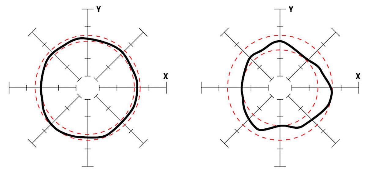
Roundness is the tolerance that controls how closely a shaft cross-section matches a mathematically perfect circle. Shafts that are out of round by even 0.0001 inch create preloading on some of the ball tracks, causing uneven wear, premature failure and shortening bearing life by as much as 50%. High precision applications require a roundness tolerance of 0.000080 inch, which manufacturers achieve

Figure 1: Shaft correction factor reduces dramatically as HRC hardness drops below 60.
Figure 2. These two plots of shafts illustrate different roundness tolerances. On the left, a proprietary centerless grinding process produces shafts with a roundness tolerance of 0.000080 inch. by a process known as centerless grinding, as shown in Figure 2.
Cylindricity is a measure of the degree of conformance of the shaft (or linear race of the linear ball bushing bearing) outside surface to a true cylinder. Taper is a cylindricity measure of the change in diameter any place along the length of the shaft. For linear motion applications, look for shafts with a maximum taper of half the diameter tolerance over the length of the shaft. This ensures uniform distribution of bearing loads and maximizes bearing travel life.
Material Matters The most common materials used in shafts are carbon steel, 52100 tubular carbon steel, 440C stainless steel, 300 series stainless steel and aluminum. Each has unique capabilities, and it is critical to match each to the application.
Carbon steel is the most commonly applied shafting material for linear motion applications, representing more than 85% of all shafting sold. It is the least expensive and, when processed, results in the hardest and deepest case, as well as high yield and tensile strength. It is highly versatile and has multiple plating options that add corrosion and wear resistance.
The most common grades of carbon steel available in North America include 1050, 1055, 1060 and 1566. These follow the AISI/SAE numbering systems, in which the first digit indicates the type of steel, the second digit is for special alloys that may be added, and the last two digits represent the percentage of carbon in the material. The percentage of carbon is the biggest differentiator among shafting materials and determines the maximum hardness achievable.
For maximum performance in most linear applications, look for carbon steel material with a carbon content greater than 0.60% and manganese content greater than 0.05%, which allows for the hardest and most uniform Rockwell hardness values and case depths. When corrosion resistance is required, an optional plating, such as chrome, can be applied. 440C stainless steel is a popular material for industrial automation because due to its corrosion resistance and hardenability. As shown in Figure 1, 440C’s typical hardness range of 50 to 55 HRC would reduce shaft life by 20 to 50% compared to carbon steel. A chrome-plated carbon steel shaft will offer better life if corrosion resistance is needed.
Designers needing non-magnetic materials often choose 300 series, but this is not suitable for use with linear ball bushing bearings because they do not offer any hardenability. 303 stainless does have a high sulfur content, which gives high machineability but reduces corrosion resistance and toughness. There is a 304 grade which does have exceptional corrosion resistance to chemical and atmospheric conditions, but it is less machinable than 303 and 316 grade. The 316 offers even less machineability than either 303 and 304 series but provides
more corrosion resistance than both.
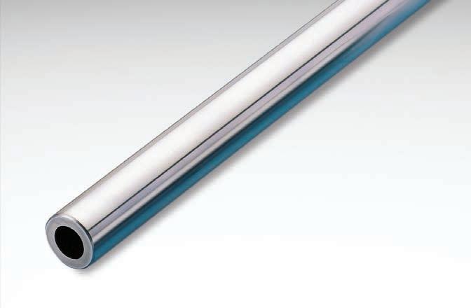
Motion system designers often choose 52100 tubular carbon steel when they want a lighter weight shaft or prefer to route fluids, lines or other components through the shaft (Figure 3). The tubular design reduces weight by 29 to 56%. It is bearing-grade chromium steel with a carbon content that allows for good hardenability with hardness values in
Figure 3: Tubular carbon steel shafts are light weight and allow fluids, lines or other components to be routed through the shaft.
the range of 58 to 62 HRC.
Aluminum shafting is usually offered with either a ceramic or hard-anodized coating. The coating hardness is nominal at the surface level only. The shaft underneath the coating is soft and would deform at high point loading of a linear ball bushing bearing. The benefit, however, is a significant weight reduction compared to other shafting materials, while also offering good corrosion resistance. When “soft” shafting is used, plain bushings that do not contain ball bearings are selected to prevent damage to the shaft, while still providing linear motion.


Configuration Basics How the shaft and bearing are configured will also impact accuracy and durability. These include the ratio of the stroke length to bearing length, the number of shafts used, the number of bearings used and the aspect ratio between the parallel shafts and bearings.
In most applications, the shaft receives less stress than the bearing plate because motion is spread across a long distance and will outlive the bearing. But when the shaft stroke is less than twice the bearing length, the situation reverses. Higher stress cycles accumulate on the shaft rather than on the bearing plate, limiting its lifecycle. Although the application will dictate the stroke parameters, the designer should include a shortstroke lifecycle correction factor when setting the dynamic load rating (D-rating) during design.
Two shafts are always necessary because a round bearing cannot account for moment loads. This does, however, make installation more difficult because parallelism between each shaft must be within 0.001 inch over the entire length of the system.
Likewise, there should be two bearings per rail to achieve equal load. This also allows the designer to take advantage of a half-degree self-alignment feature that is available in certain round rail bearings. Installing more than two bearings would not be prudent, however, because equal load sharing and alignment would be difficult to achieve.
The maximum aspect ratio between the parallel shafts and related bearings should be 3:1. As shown in Figure 4, spreading the bearings on the shaft at 1/3 the distance between the parallel shafts is recommended.
Having an informed understanding of the factors that impact precision and durability will help designers make the optimal shafting choices for their applications. Knowing the characteristics of the production process, materials and configuration options will make it easier to sort through the advantages and limitations of available options. |DE
www.thomsonlinear.com
Charles Isaac is the product line manager for linear bearings and guides at Thomson Industries, Inc.

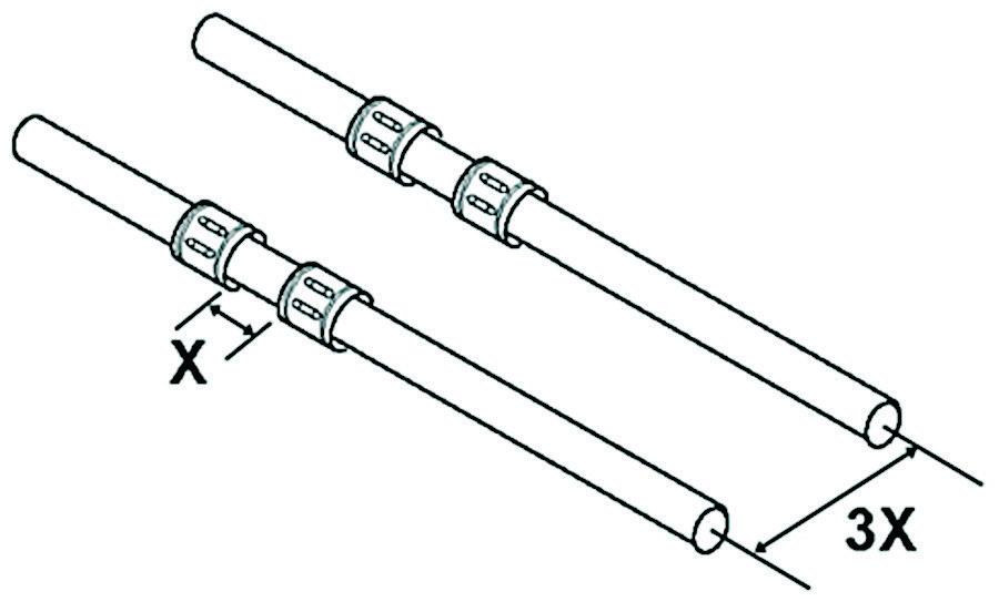
Figure 4: Spread between multiple bearings should be 1/3 the distance between parallel shafts.
AUTOMATION
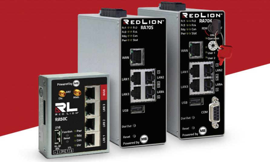
INDUSTRIAL ROUTERS Red Lion has launched its Secure Remote Access Platform that centralizes the management of routers. The remote access routers offer Simply.Connect technology that enables the setup of routers in under two minutes using only a smartphone, the company says.
The platform is based on RLConnect24, a remote service portal that provides a centralized site to monitor and manage deployed assets and users. RLConnect24 also offers data visualization, geographic mapping, data logging, and alarms based on operational or system-generated data.
The RLDialUp client software lets operators securely connect their PC to remote assets for maintenance and configuration. The routers are industrial-grade gateways that offer optional LAN,WAN, serial, USB, Wi-Fi or 4G LTE connectivity.
Red Lion also launched its RA10 industrial firewall, which can learn and self-configure to help secure older assets, avoid address conflicts and/or logically isolate machines or groups of machines. www.redlion.net ETHERCAT TERMINALS Beckhoff Automation introduced its EL51xx line of EtherCAT terminals with built-in incremental signal

analysis for 5V incremental encoders via RS422, TTL signals or open collector interfaces. Available in four models, the terminals acquire incremental signals with frequencies up to 5 MHz and feature many parameterization options. Each terminal offers an integrated sensor supply, which is parameterizable to 5, 12 or 24V. Additional integrated functions include rotary axis functionality, workpiece measurement and standstill monitoring. The measurement of period, frequency and speed with a resolution of 10ns is also available. In addition, the terminals implement a duty cycle measurement of the incoming signal. www.beckhoff.com
MOTION CONTROLLER ACS Motion Control launched its ECMsm, a compact 2- or 4-axis motion controller with internal drives, The first product in the company’s Economical Control Module line, the controller provides up to 5/10A per axis with 12-48 VDC drive supply. The ECMsm features a multi-processor architecture and universal servo drive technology to integrate and control most types of motors and stages. Other featues include ACSPL+ real-time programming with up to 6 simultaneous threads and comprehensive host programming libraries. The controller’s interface is compatible with multiple motor types on each axis including brushless, brush, voice coil, or stepper motors.In additon, the controller integrates Safe Torque Off (STO), SS1 functional safety capabilities. www.acsmotioncontrol.com
MOTION CONTROL
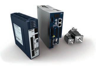
MOTION CONTROLLERS Emerson released its latest PACMotion servo motion control portfolio that includes a motion controller, servo motors, servo drives and motion configuration software. The PACMotion PMM345 motion con-
troller connects directly into the PACSystems RX3i programmable logic controller backplane with synchronized motion for up to 40 coordinated axes. The controller operates exclusively with PACSystems RX3i controllers. The controller also enables the company’s on-the-fly electronic reconfiguration which lets users implement rapid changeovers without stopping production. www.emerson.com
SERVO MOTOR JVL unveiled its MAC1500 AC servo motor with built-in controller, Nano-PLC and direct AC mains supply. With a length of 182mm, the 1500W motor provides a torque of 4.78/14.3 Nm at 3000rpm. Powering the motor requires connection of the main voltage of 3x400VAC through the M23 connectors. Control voltage for the encoder and microprocessor circuitry is 24VDC: In an emergency-stop situation, encoder position and other values are maintained by this control voltage. The integrated MAC1500 motor doesn’t require a separate servo driver or controller in a control cabinet. In addition, the motor and controller can be replaced as a single integrated unit. www.electromate.com
STEPPER MOTOR CONTROLLER Optimal Engineering Systems, Inc. (OES) has introduced its ICAD Series of integrated motion controllers and drivers for 2-phase stepper motors. Available as 1-, 2-, 3- and
4-axes modules, they are designed for NEMA 8 to NEMA 42 stepper motors. These 6- by 8-inch, integrated controllers incorporate high resolution micro-stepping drivers for precise positioning. Other features include home and limit switches per axis, joystick interface, TTL/CMOS inputs and outputs, quadrature encoder feedback, USB and optional Ethernet interfaces permits each module to be customized for specific applications. The ICAD series is powered from a single power supply up to +48 VDC. The high voltage power supply allows for high speed operation. www.oesincorp.com
WEBINARS
FLUID POWER
VALVE TERMINAL Festo unveiled its VTSA-F-CB, a valve terminal with serial communications added to the VTSA line’s existing parallel communications. In addition, the terminal’s internal bus system allows users to actuate up to 96 valve addresses, in four zones, on one valve terminal and one fieldbus node. The VTSA-FCB, supports mixing 18mm and 26mm valves on the same manifold. The ter-

WHY WEBINARS? • Full turnkey execution, including moderator provided by Design Engineering • Engage with the right audience • Present relevant, interesting content • Receive full digital marketing support over several weeks • Full lead list provided within 24 hours of conclusion of webinar

Contact us for more details on how to book your webinar.
Paul Burton | Senior Publisher T: 416.510.6756 | M: 416.997.0377 | pburton@annexbusinessmedia.com minal also features four different CPX/ pneumatic interfaces: A basic interface when safety control is not required, two integrated PROFIsafe versions (one to control three safe valve zones, another to control two zones with one safe output). The last version makes it possible for an external safety fieldbus module to directly control three pneumatic safety zones. Configuration options include a pilot air switching valve and a safety soft start/quick exhaust valve for slow startup. And the new vacuum generator VTSA-F-CB has an air saving feature with ejector pulse. www.festo.com
DIVIDER-COMBINER VALVE Webtec unveiled its FDC140, a high-accuracy hydraulic flow divider-combiner valve. Designed to drive two cylinders or motors in close unison, the spool valve offers a flow capacity of 140lpm (37 gpm) and above. FDC140 valves can divide a single flow into two separate flows. These will always be in the same ratio to one another regardless of any pressure differential (unequal load). The FDC140 delivers accuracy of ±1.5%. A single flow can also be divided into two unequal flows, with split ratios extending from 10-90% (in 10% increments).Another feature of the three-port FDC140 is its maximum working pressure rated
at 350 bar (5000 psi). Featuring an SG iron body, steel components and NBR seals, the FDC140 can be used with HLP mineral and synthetic oils, as well as HFC fire-retardant fluids. Operating fluid temperatures extend from -30 to +100°C (-22 to +212°F). www.webtec.com
ACTUATORS
ELECTRIC CYLINDER Festo has added the EPCE electric cylinder to its Simplified Motion Series (SMS). The actuators in the series integrate a servo drive, controller, electronics and two on-board control options as standard: Digital I/O and IO-Link. The EPCE line offers a number of variants, based on the location and number of piston rod(s), left or right, front or rear, etc. Units with 1-4 piston rods are available, and there are through-piston rod as well as dual opposite-direction piston rod variants. All parameters are set manually on board the device. No software or special expertise is required to get the unit up and running. Extended functions are possible with IO-Link. www.festo.com
LINEAR VOICE COIL ACTUATOR Moticont has added the LVCM-016010-01 linear DC motor to its line of linear voice coil actuators. At 0.625 in. (15.9mm) in diameter and a length of 0.63 in. (15.9mm) at mid-stroke, the miniature voice coil actuator has a continuous force of 5.9oz (1.6N) and a peak force of 18.6oz (5.2N), and features a 0.125 in. (3.2mm) stroke.Each end of linear actuator has two 2-56 UNC-2B threaded mounting holes in the housing and two 2-56 UNC-2B threaded mounting holes in the coil end on 0.250 in. (6.35 mm) centers. A plugand-play system including an encoder and servo controller is also available. http://moticont.com