31 minute read
WEST TECH REPORT

from EPT AUG2021

Plantiga adds intelligence to insoles of athletes
BC firm earns $1.2M in funding - backed by pro star support
BY SOHAIL KAMAL, WEST COAST CORRESPONDENT
Plantiga, an AI-powered sensor insole and software platform has garnered $1.2M in funding to accelerate its growth. The firm’s users and clients are impressive. These include most major league sporting leagues in North America, including the NHL, NBA, MLB, NFL and MLS, plus high-end sports medicine clinics, and both the US and Canadian militaries. The company’s sensor insoles and software enables the measurement and analysis of human movement to help athletes become more resilient and perform at their best.
West Coast Report recently had the opportunity to meet with Quin Sandler, CEO, and Bobbi Venier, head of growth, about the impetus for starting Plantiga, why their products are so important to athletes, and what challenges lie ahead for them as they refine their user interface and software.
“Our goal is to positively impact millions of people by focusing on optimizing both their movement health and performance,” says Sandler, founder and CEO of Plantiga. “We know very little of how people move, and especially in the real-world, but the way someone moves tells us so much. We can optimize our movement patterns. We can increase mobility, range of motion, speed, and more. We can push the boundaries of what’s currently possible.”
Assesses, tracks and monitors
The motivation for starting Plantiga came from Sandler and his father recognizing early on that movements as simple as walking are critical to monitoring the health and wellbeing of humans. “We knew that if there was a way to quantify the different parts of movement, we could keep watch on subtle changes that might help us prevent injury or disease, and certainly on the other side, help improve performance.”
Plantiga assesses, tracks and monitors athlete’s individual movement patterns to determine ways to both support rehab and optimize performance.
“The touch points for each individual will be very different depending on their personal goals and what their own target activity is,” explains Sandler. “On a high level, our analytics platform and coaching is designed for individuals who are interested in pushing their limits. Metrics for each instance will be different. Walking, running, jumping - we cover it all with high fidelity data that with our coaches, can provide actionable insights for each athlete.”
It is a project that has taken over a decade to get to this stage, and a turning point came when Sandler gave a live demo for the Laker’s Timothy DiFrancesco (head strength coach) and Gary Vitti (head athletic trainer), in 2017.
Canadian Olympic sprinter Andre De Grasse (left) confers with Plantiga CEO Quin Sandler on the use of the firm’s athletic insoles.

Support ‘build-out’
“They saw the demo, and DiFrancesco liked it. He said, we’ll buy one for the entire team. That’s when I had to explain that the one his athlete was using was my only demo,” explains Sandler. This was the first time that someone else had really understood the benefits of their system. There is no other way for people to generate useful, real-world sensor data on a suite of gait and performance metrics that could drive training and accelerate results for athletes.
“From our work in pro sports, we understand how hard it is to measure an athlete when they’re competing on the court, running on the trail, wherever,” said Venier. “That’s where we come in. That’s what we do for teams, and that’s what we want to do for individual athletes. The funding we received will accelerate marketing and sales efforts while supporting the build-out of [our technology’s] self-monitoring capabilities.”
This approach will allow Plantiga to continue to hone its products with professional athletes, while laying the groundwork to expand into the general population.
From just a prototype in 2017 to earning ‘seven-digits’ in funding and growing from its current staff of 15 to 20 in the fall, Plantiga is taking steps to accelerate their success. The firm is currently manufacturing all of its products locally, while foreseeing more support will be required in reducing friction in their hardware setup and improving their software’s user interface.

To learn more, go to www.plantiga.com.
Sohail Kamal is EP&T’s West Coast correspondent. sohail@nextgear.ca
Auto group seeks to accelerate use of 5G tech
The 5G Automotive Association (5GAA) - with the engagement of EU representatives and stakeholders of the ‘Cellular Vehicle to everything’ (C-2VX) ecosystem - has discussed the latest developments, opportunities, and challenges presented by connected mobility and 5G-V2X technology at the Mobile World Congress Barcelona 2021 earlier this summer. The conference offered an overview on the broadscale improvements that connected mobility can bring to the global automotive system. The association disclosed the last global updates of 5G-V2X technology that will enable real-time connection between vehicles and their surroundings. 5G-powered vehicles are expected to hit the European market this year, as 5GAA members are leading C-V2X deployment through network based, direct communications on the continent. Technological progress supports more advanced use cases and the combination of longrange and short-range connectivity will grant the optimal setup for safety and efficiency of traffic. “In the next two to three years, our association expects to see mass deployment of vehicle-to everything (V2X) use cases geared towards improving traffic efficiency and road safety around the world”, said 5GAA director-general Johannes Springer. From 2024 onwards, 5GAA further anticipates the large-scale introduction of advanced safety and automated driving use cases supported by C-V2X. 5GAA supports the ecosystem by identifying these required use cases and services which are expected to be enabled by 5G-V2X in the coming decade. This enables European stakeholders to engage and collaborate in order to scale up V2X services and deliver societal benefits. 5GAA also underlined the strong need for a harmonized regulatory approach that will stimulate innovative business models and a technology-neutral regulatory framework that will be focused on service delivery and foster market-led innovation. Only an enabling and future-proof regulatory environment, conducive to C-V2X rapid deployment by OEMs and road authorities, will improve road safety and reach climate-neutrality.
The association highlighted 5G-powered vehicles are already commercialized in China. However, there are some relevant improvements in C-V2X implementation and 5G accessibility on roads in Europe. Many cities and road operators are starting to offer internet interfaces with real-time traffic information such as red light space, slippery roads and even wrong-way-drivers warning.
For one, Dieter Hötzer – vice-president of automated driving systems at Bosch - illustrated the Wrong Way Driver Solution developed by the 5GAA member company, as a clear example of technology that greatly impacts road safety. The software needs a GPS signal transferred to a cloud system that alerts drivers going the wrong way and warns other vehicles in the danger zone, sending out almost instant push notifications.


The Cord Compass for Navigating Tight Spaces— NEMA Angled Cords!
Interpower® offers 8 different angles of the NEMA 5-15 cord. When limited space between equipment and the power connection make the direction of the cord critical, an angled cord minimizes the space between connectors reducing the strain on both plug and cord. Cords allowing 8 directional angles or “headings” will navigate past tight angles and minimal space (such as equipment flush against walls) to find connectivity.
• Made in the U.S.A. • Same Day Shipping on in-stock products • No minimum order requirements
Order Online! www.interpower.com
Business Hours: 7 a.m.–6 p.m. Central Time INTERPOWER | P.O. Box 115 | 100 Interpower Ave | Oskaloosa, IA 52577 | Toll-Free Phone: (800) 662-2290 | Toll-Free Fax: (800) 645-5360 | info@interpower.com
Coating electric vehicle charging stations for safer, tougher reliability
Which conformal coating has the best chemical composition to deliver all attributes & operational function?
BY CALVIN JENNINGS, SENIOR DIRECTOR AUTOMOTIVE, HZO
The emergence and development of electric vehicles (EVs) have consumers around the globe switching to electric mobility. The BBC recently reported that 20% of all new cars sold globally will be electric by 2025. EVs have finally attained mainstream status, and sales are beginning to overtake those of internal combustion vehicles. And, there are solid reasons for doing so. No fuel means no emissions. This is particularly important for those interested in decreasing their impact on the environment through transport. Running costs are minimal, as are maintenance costs. Where performance was once an issue, there is hardly an automobile manufacturer that has not jumped on the EV bandwagon. The competition has rocketed EV performance.
However, there continue to be perceived and real technical barriers to the widespread adoption of electric vehicles. The availability and reliability of a fast-charging infrastructure continue to be the major hurdle. Although home charging is where most electric vehicle charging happens, long-distance driving requires a ubiquitous network of working charging stations to make long-distance travel feasible. According to Deloitte, as of February 2021, there were almost 100,000 charging outlets for plug-in electric vehicles (EVs) in the United States. Regardless of where charging takes place, charging stations can fail – and when they do, drivers become stranded.
Electric Vehicle Supply Equipment (EVSE), commonly called charging stations or charging docks, supplies electric energy to recharge electric vehicles. They are designed and manufactured into the EV charging standard for electrical safety for the user, the vehicle, and the power grid. Several residential and commercial ac and dc EVSEs configurations are designed to deliver a range of power outputs, load capabilities, and


When a connection is made to the EVSE’s, the control module assesses power levels and whether the cable is connected correctly, while sourcing potential ground fault.
20%
of all new cars sold globally will be electric by 2025 offer different connector types. North America, Europe, and China have regional standards, and some are vendor-specific, like Tesla. Regardless of the differences, all EVSEs have components that enable them to perform the same essential functions.
Charging stations are typically housed in National Electrical Manufacturers Association (NEMA) rated enclosures with either a box on the charging cable, a wall-mounted unit, or a tower. Ac power flows into the chamber through a plug for portable units or a hardwired connection for permanently placed units. A cable runs from the enclosure with a connector that ties to the vehicle’s charging port. In Direct Current Fast Charging (DCFC,) the EVSE enclosure also contains components that convert ac power to dc.
The internal components of an EVSE consist of a power source, three-phase electric power, charging points, masters, a server and database, asynchronous serial connections, communication TCP/IP (Transmission Control Protocol/Internet Protocol), and slaves. There is the main relay for switching power to the vehicle on or off and a module that controls the main relay. When in use, there are high voltage connector terminals for charging and pilot connectors for a low voltage connection to the EVSE’s control module. When a connection is made, the control module assesses power levels on the pilot connectors, indicating whether the cable is connected correctly and whether there is a ground fault.


It also verifies that the vehicle’s systems are ready to receive a charge and the charging station is ready to deliver power. The main relay then powers up the cable connected to the EV.
Although there are many different EVSE configurations, all the connectors have pins that enable basic functions. More sophisticated charging stations contain microcontrollers that can be programmed to perform specific tasks such as adjusting power output, monitoring charging progress, connecting to the Internet, and interacting with mobile apps that enable users to control the charging station remotely.
Charging stations are typically located outside, which makes them vulnerable to external sources. They are susceptible to voltage transients or electrical surges resulting from a sudden release of energy previously stored or induced by heavy inductive loads or lightning. Being outside also means the
0.5ΜM
Parylene has emerged as the conformal coating of choice for various industries, including automotive delicate internal components are susceptible to the elements. To compound the issue, in-network EVSE failures can impact other chargers or transmit across power lines and affect other electrical power equipment.
The realistic and economical approach to protecting EVSEs is with conformal coatings, polymeric film-forming products that protect circuit boards, components, and other electronic devices from adverse environmental conditions. As the name implies, they conform to the structure and environment of the items being coated, thereby providing increased dielectric resistance, operational integrity, and protection from corrosive atmospheres and contaminants, including humidity, heat and cold, mold, dirt, and dust.
The question is – which conformal coating? The chemical composition of each determines its attributes and operational function.
Acrylic Resin – Acrylic conformal coating provides fair elasticity and general protection – or what is considered basic, entry-level protection. It is recognized for high dielectric strength and adequate moisture and abrasion resistance. Acrylic is easy to apply and remove, making rework and field repair practical and economical. Still, it does not protect against solvents and vapors, making it less than ideal for many applications.
Silicone Resin – Silicone conformal coating is moisture, chemical, salt spray, and fungal resistant, making it appropriate for high-humidity environments. As a soft and flexible solder-through coating, it has good dielectric properties that can withstand wide temperature ranges. Its rubbery nature makes it unresistant to abrasion, but this property makes it resilient against vibrational stresses. This quality makes removal a challenge, requiring specialized solvents, long soak time, and agitation from a brush or an ultrasonic bath.
Urethane (Polyurethane) Resin – Urethane conformal coating is known for excellent moisture, chemical, solvent, and abrasion resistance. It is challenging to remove. They are applied as single or two-component formulas with claims of suitability for printed circuit boards.
Epoxy Resin - Epoxy resin conformal coating is usually available as a two-part compound and creates a very hard coating. It enjoys humidity resistance and is not generally permeable. It has high abrasion and chemical resistance, which makes removal very difficult once cured.
Parylene – Parylene, with its unique chemistry, and deep molecular reach, has emerged as the conformal coating of choice for various industries, including automotive, medical, aerospace, military, industrial, and consumer electronics. When compared to acrylic, silicones, urethane, and epoxy coatings, Parylene has all the properties and characteristics necessary to help advance technologies. There is no liquid phase with Parylene, and it is truly conformal. It can create a uniform controllable thickness that is entirely pinhole-free at thicknesses greater than 0.5µm, even for the most intricate and complex shapes. This ultra-thin coating can penetrate spaces as narrow as 0.01mm.
Parylene is inert, insoluble, thermally stable between -200°C and 125°C and higher, has a dielectric strength of 7 kV/mil, and has high elasticity with an elongation break of 200%. It acts as a dry film lubricant, eliminates the need for liquid release agents, and protects from a range of contaminants, including moisture, corrosive fluids, chemicals, gases, and fungus.
Parylene is applied near room temperature, which means any object that can be exposed to medium vacuum can be coated. Overall, its distinctive properties can be used to provide protection solutions to a wide variety of applications. Manufacturers are often amazed at the sheer number of items that can be effectively coated with Parylene.
As the barriers to electric vehicle adoption are removed, they are increasingly becoming a realistic and viable transportation option. They are nothing, however, without reliable charging stations. The automotive industry routinely turns to Parylene coatings to provide enhanced protection for all kinds of electronic circuitry. With so many automakers preparing to move away from combustion and hybrid-powered vehicles to full EVs, EVSEs will be held to the same durability and dependability standards consumers expect in their vehicles.
Calvin Jennings joined HZO with more than 20 years of experience in the automotive electronic business working for such companies as Ford, Visteon, Continental, and HBPO. Jennings worked in many areas of the automotive industry, from manufacturing and design engineering at Ford to business development and sales at Visteon, Continental, and HBPO. Jennings holds a B.S. in Electrical Engineering from Widener University and an MBA from the University of Michigan, Ross School of Business.
Essential for future automotive electronic and electrical architectures
Automotive display systems are currently undergoing accelerated evolution due to industry trends in connectivity, automation, sharing and electrification. Advanced driver-assistance systems (ADAS), digital cockpits, in-vehicle infotainment (IVI) and autonomous driving systems (ADS) are driving a rapid proliferation in the number of in-vehicle displays and the need for ever-increasing display resolutions, frame rates and colour bit-depths.
The resultant multigigabit net data throughputs required to connect all of these displays present a significant design issue for future vehicles, requiring the development of innovative electrical and electronic (E/E) architectures that leverage the latest display technologies. These advanced display systems must also meet the stringent reliability, power, weight and electromagnetic compatibility (EMC) requirements demanded by the automotive industry.
The use of industry standards for displays has solved similar challenges in adjacent industries, such as mobile phones. This article will explain how following a standards-based approach is also essential to solving the automotive display connectivity challenge.
Top 5 technical considerations for connecting automotive displays
The challenge of automotive display connectivity raises five principal technical considerations that need to be addressed when developing automotive E/E architectures:
1Bandwidth and latency: As shown in the image and table, more displays are being integrated into vehicles to support the increasing demand for ADAS and ADS — replacing traditional analog instrument clusters, mirrors and mechanical buttons, and adding new displays to support IVI services and to enable digital vehicle customization. The increasing number of displays combined with ever-increasing display resolutions, frame rates and color bitdepths will require multigigabit-per-second, ultra-low-latency connectivity, with the total
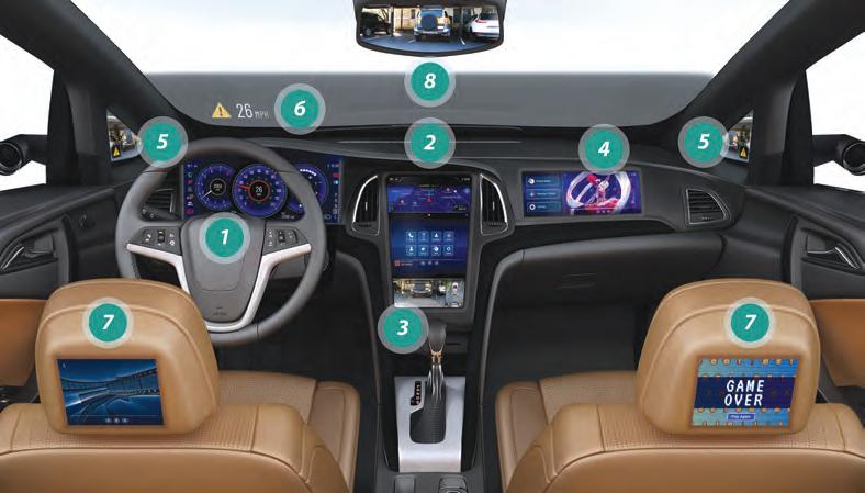
Figure 1 Increasing numbers of in-vehicle displays.
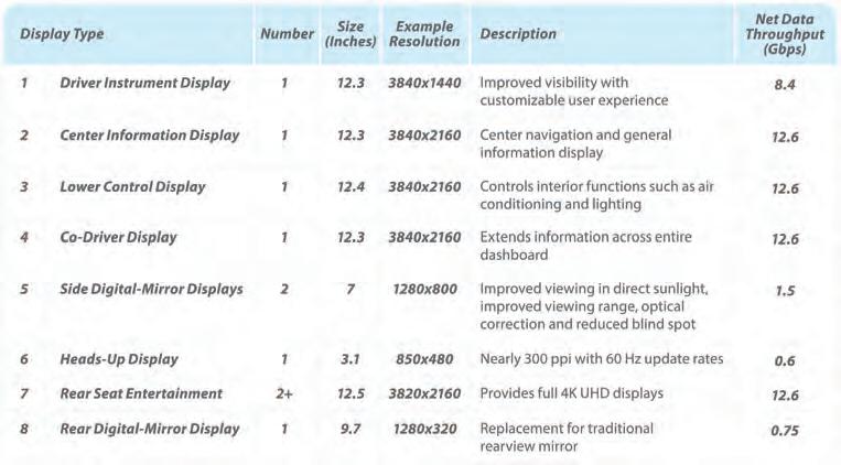
Figure 2 Example of in-vehicle display types and net data throughputs.
net data throughput required to connect displays expected to increase significantly with each new generation of vehicles.
2Electromagnetic interference (EMI) immunity:
Harsh in-vehicle environments present significant challenges to multigigabit communication technologies, which are required to operate at significantly higher symbol rates and at much higher in-band frequencies. To ensure safe and resilient operation of high-throughput data links over the vehicle’s lifespan, communications links must provide ultra-high immunity to any EMI effects by implementing noise cancellation and error correction mechanisms that target the negative effects of automotive EMI.
3Cable harness complexity: The cable harness is presently one of the heaviest and most expensive components within a vehicle. Connectivity solutions for in-vehicle displays must, wherever possible, minimize the complexity of the cable harness, reducing the cable shielding and number of conductors to a minimum to save cost and weight, and allowing use of inline connectors to enable ease of installation on the production line. Connectivity solutions must also
protect against cable harness degradation due to cable aging and flexing.
4Functional safety enablers: ADAS and ADS applications must meet Automotive Safety Integrity Level (ASIL) requirements, from ASIL B through ASIL D, as defined within ISO 26262. Features that enable functional safety within display connectivity solutions to detect loss of packets, frozen links and loss of communication are essential to meet these stringent requirements.
5Engineering effort: Integrating advanced displays into vehicles can require the use of many different software and hardware components, sourced from many different vendors. Developing bespoke connectivity solutions in-house, or with a limited number of suppliers, can significantly increase engineering effort and component costs, placing the whole cost burden, including development, test and validation, onto a single automaker.
How a standardized automotive display connectivity framework can overcome these challenges
Use of a standardized automotive display connectivity framework, such as the one provided by the MIPI Automotive SerDes Solutions (MASS) display specifications, can help automakers overcome all of the challenges described above. Unlike individual specifications, which solve only one component of a display solution (such as just providing the physical layer), a framework solution provides physical and protocol layers together with key features such as display stream compression and functional safety enablers, creating a fully integrated solution for the automotive industry.
The MASS display framework, shown above, provides a complete automotive connectivity solution, incorporating a suite of industry specifications:
• MIPI A-PHY:
A high-speed, low-latency (< 6?s), longreach (up to 15m) asymmetric serializer/ deserializer (SerDes) physical layer interface. A-PHY employs dynamic pulse amplitude modulation, just-in-time interference cancellers and PHY-level retransmission mechanisms to ensure ultra-high noise immunity and maximum link robustness. It supports heterogeneous point-to-point and daisy-chain display topologies and optional power delivery over a single cable (coaxial or shielded twisted pair), eliminating the need for proprietary asymmetric PHYs, simplifying in-vehicle communication networks and reducing cost, cable harness weight and development time.
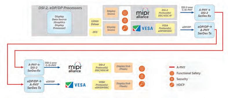
Figure 3 MIPI Automotive SerDes Solutions (MASS) display connectivity example.
Figure 4 MIPI Automotive SerDes Solutions (MASS) display specifications.
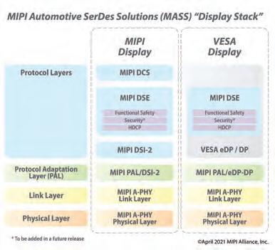
• MIPI Protocol Adaptation Layers (PALs):
Specifications that allow display components based on MIPI Display Serial Interface 2 (MIPI DSI-2) and VESA Embedded DisplayPort and DisplayPort (VESA eDP/DP) protocols to map their video, audio and control data to A-PHY’s A-Packet format for transmission over long-reach A-PHY networks.
• MIPI DSI-2 and VESA eDP/DP:
Industry-leading display protocols to enable long-reach source-to-sink connectivity between automotive displays and their associated electronic control units. Already extensively adopted within multiple industries, including mobile, computer and automotive, use of these protocols dramatically reduces engineering effort and cost.
• MIPI Display Service Extensions (MIPI DSE):
A new specification that standardizes functional safety enablers to help display solutions meet ISO 26262 requirements from ASIL B to ASIL D. Enablers include link failure detection, timeout monitoring, cyclic redundancy check to detect data transmission failures, and a message counter for replay protection. High-bandwidth Digital Content Protection (HDCP) is also enabled
by DSE, and additional security features will be added in future releases.
• MIPI Display Command Set (MIPI DCS):
A standardized command set for control functions and supply of data to displays using MIPI DSI-2. It specifies commands for setup, control and test functions, including the control of settings such as resolution, width and brightness, thus significantly simplifying integration and design cost.
• VESA Display Stream Compression (DSC) and VESA Display Compression-M (VDC-M):
Incorporated into DSI-2, codecs that offer guaranteed low-latency performance and are visually lossless for images and videos (DSC at 8 bits-per-pixel compression and VDC-M at 5-6 bits-per-pixel compression). Already widely adopted within multiple industries, including mobile and the Internet of Things (IoT), use of these standard compression technologies for automotive display applications not only massively reduces connectivity bandwidth, but also dramatically reduces engineering effort and cost.
Conclusion
Use of industry standards such as MASS solves key automotive display connectivity challenges, drives interoperability between different vendor solutions and leverages economies of scale by amortizing engineering costs over larger volumes of components spread across the whole industry. Most importantly for automakers, the use of standards removes the burden of designing (or selecting) a proprietary interface for the next E/E architectures, allowing automakers to focus on ‘higher-value,’ product-differentiating technologies that sit higher up the protocol stack.
This article was written and submitted by James Goel, MIPI technical steering group chair and display working group vice chair. Read more about the MIPI Automotive SerDes Solutions display framework.
Autonomous vehicles drive AI chip innovation
BY BIN LEI, CO-FOUNDER & SENIOR VICE-PRESIDENT AT GYRFALCON TECHNOLOGY INC.
The technology in our cars is undergoing a radically dynamic transformation. Software monitors the engine, plays the music, alerts the driver to oncoming traffic hazards and provides so many more functions. However, the old adage that software is slow and chips are fast is supremely relevant as vehicles become autonomous. No room for error exists when the car is driving itself. As we get closer to full autonomy, chips will need to usher in the next gen.
Why are cutting-edge chips necessary for Edge AI? AI requires a specific architecture that is more appropriate for AI application processing. The trend is to use Tensor architecture as opposed to Linear or Vector processing that is typically used in CPU, DPU or GPU, respectively. Cutting-edge chips or dedicated co-processors are becoming the mainstream for on-device, edge, and even cloud AI processing. Edge AI has other benefits (besides its architecture) in terms of its locality, privacy, latency, power consumption limitation, and mobility support.
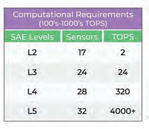
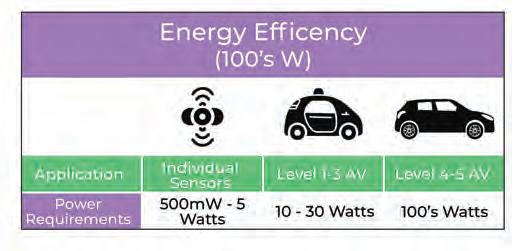
Q: Why is autonomous driving so difficult from a tech perspective? Autonomous vehicles require processing massive data captured by the sensors (camera, LiDAR, Radar, and Ultrasound). And, it has to provide real-time feedback, such as traffic conditions, events, weather conditions, road signs, traffic signals and others. This requires high trillions of operations per second (TOPS) to process multiple challenging tasks (eg, object extraction, detection, segmentation, tracking, and more) simultaneously. It also consumes high power consumption depending on the operation. Lastly, high speed processing, reliability and accuracy are very important and need to be better than humans. driving, every single case was a new case that the machine learning did not quite know how to react or reacted wrongly. It takes time, but we must do it correctly. Over 90% of car accidents are due to human errors and although human mistakes can be forgiven, machine errors are not. AI accuracy can be increased due to learning capabilities and algorithms used. Besides algorithms, infrastructure and government regulations are important to make autonomous driving possible.
Q: What is the role of sensors (ie, cameras, LiDAR, ultrasonic, radar)? Cameras are typically used for vision processing, which is becoming aware of the surrounding environment for object detection, identification, segmentation, (lane) tracking, blind-spot monitoring, parking assist, traffic sign recognition, and color information. Cameras typically do not provide distance information. LiDAR is mostly used for 360-point detection with high accuracy and resolution. LiDAR is very expensive and offers no color information. Radar is used for object detection with high-to-low resolution and is useful at long range, but cannot distinguish what the objects are. Ultrasonic is often used for parking assist, blind spots, ACC (automatic cruise control) with stop and go.
Q: Describe the computational challenges for autonomous vehicles above L3. Currently, most autonomous vehicles are using GPU (graphic processing chip) for their core AI processing. GPU is not as fast or cost-effective as a custom chip (ASIC). Ultimately, we need a dedicated AI autonomous processor. However, one of the biggest issues is power consumption.
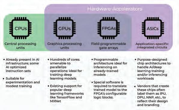
Q: For autonomous AI, what chips are most widely used? Central processing units (CPUs) are general-purpose processors with linear architecture. Ideally, it is desirable to use CPUs for more general (but important) non-AI tasks. Overloading CPUs by AI processing should be avoided if possible. Graphics processing units (GPUs) are traditionally used for graphics and gaming. However, due to its flexibility and relatively high processing power, It can be used for AI training and edge applications. There are other issues such as the data transfer between the GPU and the CPU ends up being one of the big constraints of the system. Other main disadvantages of GPUs are power consumption and cost. GPUs are mostly used for cloud AI and its flexibility and configurability capabilities. Application-specific integrated circuits (ASICs) are more appropriate for application-specific tasks with large computing processing, low cost, and power efficiency requirements, such as AI applications. Using an AI dedicated co-processor (ASIC) for AI applications is becoming mainstream particularly for Edge applications. We believe in the future, for autonomous driving, there will be dedicated processors and systems to serve the purpose that will not be GPU-based.
Q: Why is Edge computing so important for the future? Edge computing is important due to the following features: Locality, low latency, privacy/security, mobility support and power consumption restriction.
Q: How can manufacturers ensure autonomous AI mistakes are not made? If you look back at accidents or issues with their autonomous
Gyrfalcon Technology Inc., developers of high performance AI accelerators that use low power, packaged in small sized chips.
Take the path of least resistance
Increase the efficiency of your power electronics systems with our ultra-low DCR power inductors
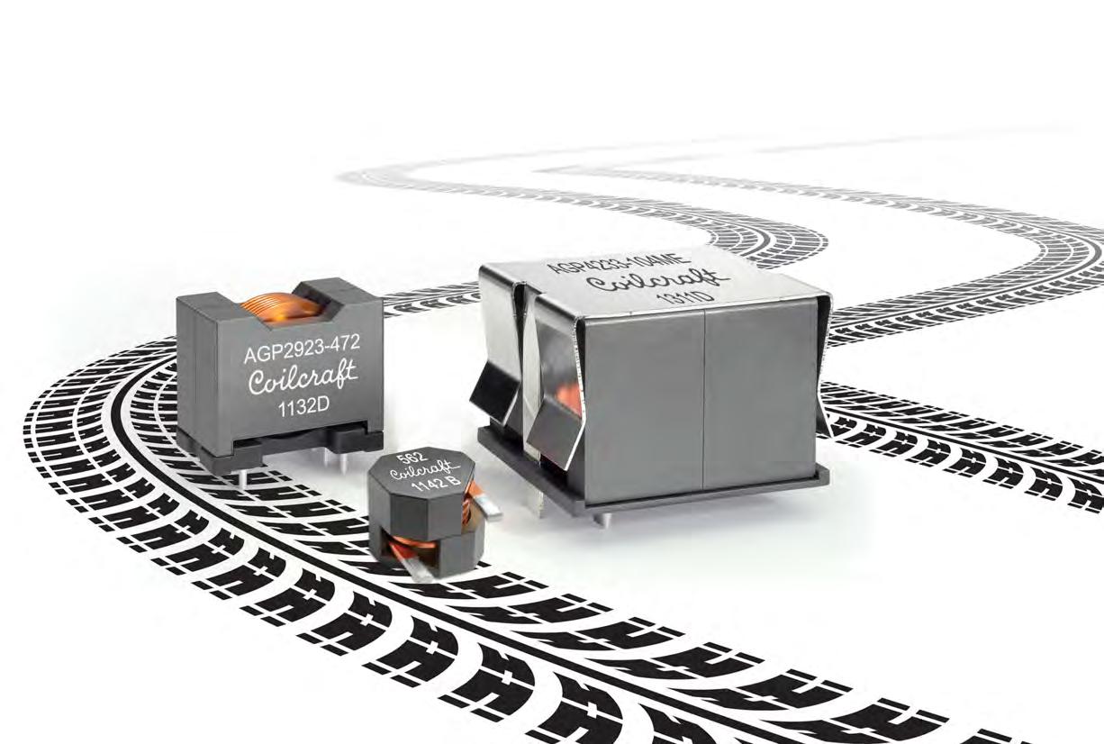
Coilcraft’s AGP/AGM Family of high current power inductors features flat-wire construction for exceptionally low DC and AC resistance, letting your power systems run cooler and with greater efficiency.
Select from a wide range of inductance values from 1.9 to 470 µH and current ratings up to 110 Amps.
All AGP/AGM inductors meet stringent AEC-Q200 Grade 1 quality standards, making them suitable for automotive and other harsh-environment applications.
Visit www.coilcraft.com/AGP to learn more and arrange for a test drive. Datasheets and free samples are always just around the corner!
Future vehicles rely on the convergence of a huge range of technologies. Electrification; sensors; connectivity; cloud computing; big data; AI – they’re all intimately connected in the functional safety and driver-assist features for autonomous vehicles.
At the lowest levels, individual sensors and integrated circuits interact in the various subsystems of the vehicle. But, it doesn’t stop there, the vehicle is part of an overall environment that includes other vehicles, pedestrians, infrastructure, and even the cloud. This makes the verification of automotive systems an enormous task.
There are literally millions of scenarios to be checked out. And each of those scenarios has variations. For example, one scenario might have the car approaching a pedestrian in a crosswalk. But that could be at different times of day, with different weather, and with different pedestrian clothing. All of this is a verification project that, realistically, could never be accomplished using physical means. All of these demands join the usual challenges of getting a cost-competitive product to market as quickly as possible. The problem is a perfect fit for verification tools that can make this process manageable. A combination of realistic scenario modeling, simulation, and mechatronic verification aim to get a new vehicle on the road quickly and efficiently.
For an autonomous vehicle to function, its systems must perform three tasks: • Sense: the vehicle must be able to sense its environment. In addition, there are many internal conditions that must be sensed to assure correct operation • Decide: those sensor outputs must be evaluated to make decisions • Actuate: those decisions must control some part of the vehicle or some aspect of its operation. All three of these elements need to be included in any comprehensive verification process.
And that presents a significant challenge, since there is no time to do physical prototyping using trial-and-error to find issues. And it’s impossible to test safety and security thoroughly in a real, physical vehicle. The only way to do extensive verification is to virtualize the entire system – environment and vehicle.
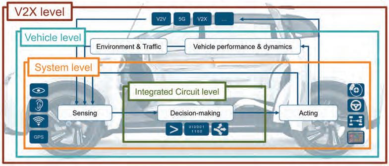
Figure 1: Vehicles are systems of systems, of systems of systems.
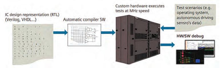
Figure 2: Veloce emulators take a design that’s been compiled for the emulator, execute the design, and allow debugging of both hardware and software.
This means that we need tools to: • Simulate real-world environmental conditions and the outputs of sensors responding to them • Verify the circuits that perform the decision-making computations, given the sensor inputs • Take the computed decisions and apply them to virtualized versions of the mechanical systems that those decisions control
Modeling the driving environment
In the first task, a tool extensively models the vehicle infrastructure like roads (or portions of roads), bridges, and intersections; physical objects like trees, buildings, and traffic signs; other vehicles and pedestrians; and weather conditions. It also has an extensive library of modeled sensors, including cameras, radar, lidar, ultrasonic sensors, infrared sensors, V2X communications, and GPS. These elements work together to allow modeling of realistic roadway conditions, with variants provided for time of day, weather, colour of vehicles or pedestrian clothing, pedestrian features, and the numerous other ways these scenarios can be tested. Together, these virtual scenarios produce the signals generated by the various vehicle sensors as they react to the scenario. Those signals can then be used to test the integrated circuits that are responsible for responding to the sensors.
Verifying the integrated circuits
When it comes to verifying circuits, simulation is a common tool used extensively for checking out pieces of the circuit. But, when it comes to verifying an entire chip, simulation is far too slow. Much of the functionality will be implemented in software, which is practically impossible to simulate – again, because it would take an extraordinary amount of time to do so. But there’s a faster way to verify silicon: hardware emulators. Unlike simulators, which use computer instructions to do their work, an emulator implements the circuit
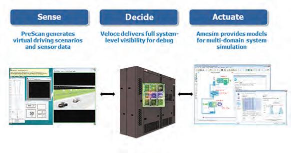
Figure 3: Together, Simcenter PreScan, Veloce and Simcenter Amesim provide end-to-end vehicle verification.
being verified in logic chips that make up the heart of the emulator. In the Siemens hardware emulator, Veloce, those logic chips have been designed to allow them to implement any digital design within the size constraints of the emulator. So, while you’re not running the actual final silicon chip – which hasn’t yet been built – you’re still using hardware instead of software, and that can speed things up by 1000-10,000 times.
One key requirement of any verification approach is visibility. You need to be able to see deep inside the circuits so that, if something goes wrong, you can figure out exactly where and why it happened. You can’t do that with a real, physical circuit because the overwhelming majority of the signals never leave the chip – so they’re not visible. Simulators give good visibility, since everything is modeled in software, but, as we’ve seen, they’re too slow.
Critically, hardware emulators also provide the needed visibility making it possible to peer into the circuits in the same way that simulation allows, but with far faster execution speeds. The circuit that you build inside an emulator acts as a digital twin of the real circuit. It allows you to develop a high-quality circuit much more quickly.
This makes verification much more efficient because you’re testing the circuit before it’s built. This means that there’s no need to wait for actual silicon to do the verification. More critically, you can find any problems before committing to silicon, dramatically reducing the chances of an expensive and time-consuming mask re-spin and raising confidence when you move into production. Importantly, scenarios and results can be traced back to requirements. This lets you converge on a complete, correct design more quickly, since the verification plan and results remain connected to the requirements that drove the design in the first place.
Verifying the response to calculations
The integrated circuits process the sensor inputs and make decisions. It’s important to verify that those decisions will have the intended effect. But the decisions affect mechanical systems that aren’t available in an emulator. A different tool is required to take the hardware emulator outputs the rest of the way through the system. Siemens has a tool that provides just such a capability, using functional mock-up units (FMUs) to simulate the effects of the emulator outputs. This is still a virtualized environment – where testing the activity of major mechanical components like the engine, the transmission, the brakes, and the steering can be done. So, for example, if a scenario shows a pedestrian jumping unexpectedly in front of the car, the camera and other sensor signals that observe this happening are run through the emulator. The emulator decides – say, to make an evasive steering maneuver, or to apply the brakes, or both. The logical signals indicating the decision can then be sent to the mechanical component simulation tool, where the steering wheel will turn by the requested amount, or the brakes will be applied the requested amount, or both. Verifying from stimulus to response
Together, these tools provide the end-to-end verification that’s so critical for ensuring that your vehicle will perform correctly regardless of the scenario and regardless of which parts of the vehicle are affected. And, it’s done completely virtually, meaning no delays for building prototypes. One need only create models – and many of them already exist in the tool libraries.
Jean-Marie Brunet is the senior director of product management and engineering for the Scalable Verification Solutions Division at Siemens EDA. He has served for more than 20 years in application engineering, marketing, and management roles in the EDA industry, and has held IC design and design management positions at STMicroelectronics, Cadence, and Micron among others. Jean-Marie holds a Master’s degree in Electrical Engineering from I.S.E.N Electronic Engineering School in Lille, France. Jean-Marie Brunet can be reached at jm_brunet@mentor.com