30 minute read
THINK GREEN


BY DR. ISABEL AL-DAHIR, TECHNOLOGY ANALYST, IDTECHEX
A new wave of electronics manufacturing is on the horizon, aiming to satisfy the increasing demand for sustainability and mitigate the impact of volatile energy prices. With the electronics industry accounting for 4% of global greenhouse gas emissions, it requires substantial innovation to reduce its environmental footprint.
Incentives to be sustainable
Sustainability within the semiconductor and electronics industries is being driven forward by government mandates and green investment initiatives. Increasingly relevant to the survival of traditional manufacturers is the conscious choice of the public to only purchase from, and even only work for, companies that prioritize sustainable practices.
Environmentalism is often perceived as an obstacle-laden with legislative red tape and burdensome disclosures. However, companies that embrace environmentalism reap long-term rewards, and as such, the negative perception is replaced by one of opportunity. The implementation of low-emission manufacturing processes or the adoption of material recycling and recovery schemes can be the financially astute choice presenting an opportunity to reduce costs associated with energy consumption, waste treatment, and superfluous steps.
As energy prices rise globally, low temperatures and rapid processing methods become more attractive. Some of these methods employ additive approaches that substantially cut waste by printing material only where needed. This spares manufacturers the costs and emissions associated with excess materials and etching required in traditional subtractive manufacturing. For example, switching to additive methods of PCB manufacturing can lower water consumption by up to 95% - an outcome that could save the sector hundreds of millions of liters of water annually.
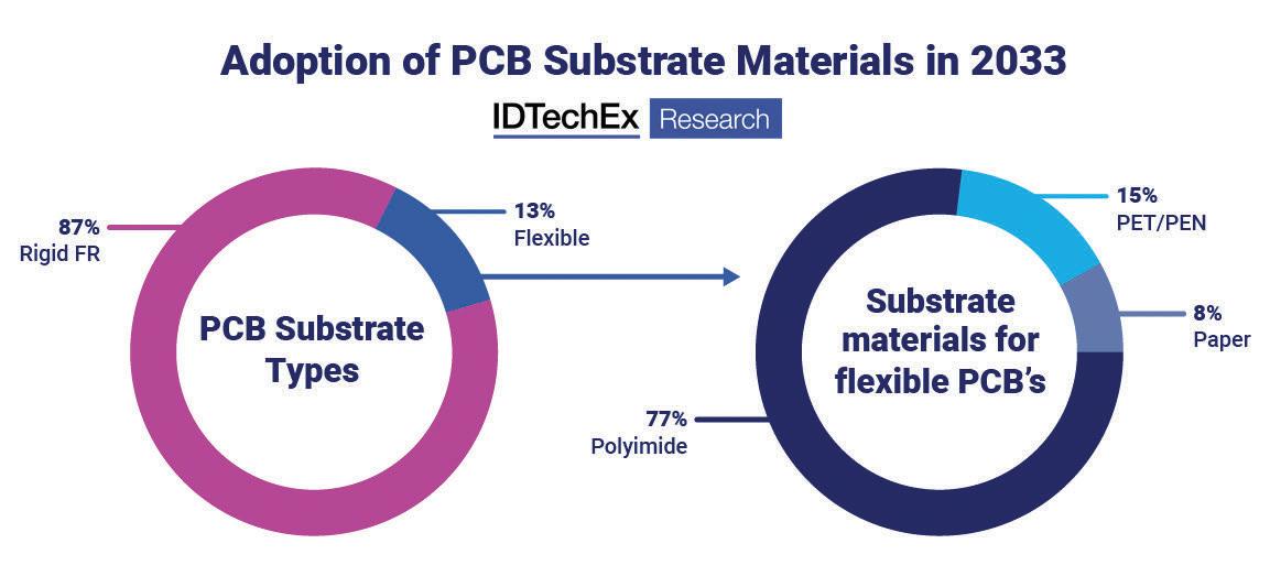
IDTechEx’s analysis expects additive manufacturing to be particularly significant to the scaling of flexible printed circuit boards. Flexible pcbs are an important part of the emerging electronics industry as they enable a wider variety of applications than conventional rigid electronics. Flexible pcbs inherently require an overhaul of traditional processing – for example, using plastic or paper rather than conventional FR substrates. Embracing a new technology enables scope for further changes, such as transitioning to new materials and additive methods. Low-temperature processing may also be imperative for pcbs made on plastics such as polyethylene terephthalate (PET), considering that these have relatively low heat tolerances.
Adoption of PCB Substrate Materials in 2033
87%
Rigid FR
PCB Substrate Types
13%
Flexible
77%
Polyimide
Substrate materials for flexible PCB’s
15%
PET/PEN
8%
Paper
Digitization for smart mfg
Sustainable electronics manufacturing presents many opportunities to be more efficient, reduce waste, and improve cost-effectiveness. Sustainable manufacturing can be facilitated through AI and IoT, as smart digital manufacturing methods automate processes.
Digital data analysis can help remove superfluous steps and illustrate where to focus efforts to eliminate excess material and energy consumption.
The past three years have been full of upheaval, with pandemics, trade wars, and energy crises dominating front-page headlines across the world. The turmoil has brought to sharp relief how fragile the multi-billion dollar electronics industry is. The global chip shortage is a salient example of the damaging consequences of supply chain disruption.
While it may not be possible to immunize supply chains against all eventualities fully, there are acts that can be taken to minimize risk and reduce emissions. One method involves reducing dependency on geographic monopolies such as the Asia Pacific region, which currently dominates electronics manufacturing. Re-distribution of the electronics industry is gaining momentum of late, with hundreds of billions of dollars worth of funding going into revitalizing localized electronics manufacturing in the West, as outlined in both the US CHIPS & Science Act and the European Chips Act.
Increasingly, access to renewable energy is becoming a major factor as companies build new fabrication facilities. Samsung has already achieved 100% renewable energy for all of its sites in the US and China, with other household name companies following suit, such as Apple, IBM, Intel, and Nokia.
The availability of renewable energy sources varies substantially geographically, with the US and Europe leading the way with clean energy options compared to much of Asia Pacific (AP). Greater access to renewable energy may give the US and Europe a new kind of leverage to encourage local manufacturing. Through substantial energy savings and energy independence, the production of various electronic components is likely to become increasingly cost-competitive with the Asia Pacific region.
Additionally, since ‘reshoring’ will require the construction of new manufacturing facilities, there’s a substantial opportunity to design and equip with sustainability in mind from the outset. In contrast, in existing production lines, much of the equipment is already depreciated, increasing the relative cost of new investments into more sustainable manufacturing methodologies.
Outlook
The electronics industry requires an overhaul of traditional manufacturing approaches contributing to global warming. Switching to low-toxicity, low-emission chemicals and processes is a key challenge to be addressed in the near future as more companies commit to attaining net-zero targets. Additionally, it is important to stay ahead of the curve as carbon prices may rise, making renewable energy the more reliable energy source to utilize.
www.idtechex.com
Highly efficient dc-dc converters extend battery run time on mobile autonomous robots

BY TDK-LAMBDA AMERICAS TECHNICAL MARKETING
Seeking a power converter with a logic level enable input (remote on/ off function) can allow the designer to turn quiescent sleep modes into deep sleep modes - such as in the application above.
We are frequently seeing articles about electric vehicles and one subject that appears frequently is how far can they travel between charges. The industrial sector is also very conscious of this aspect of battery powered equipment. Warehousing, inspection, disinfecting, security and many other applications are now utilizing robots.
These robots fall into two classifications: Automated guided vehicles (AGVs) are programmed to follow predetermined routes and if there is an obstruction, operation will be halted until the obstruction is removed is removed. Autonomous Mobile Robots (AMRs) utilize sensors or scanners and rely on mapping and data to find alternative routes to perform their function. A robot vacuum cleaner is a good example of this.
The run time of battery powered equipment is limited by two basic functions. One is the battery’s stored energy capability and the other is the amount of power drawn over a period of time. The run time could be increased by using a larger battery; however, this would increase the overall size and weight.
Run time constraints
Run-time of battery powered designs is ultimately constrained by the law of conservation of energy. This essentially tells us that the amount of energy in an isolated system is fixed. Within such a system, energy can be converted from the battery to driving a motor for example. Between charging periods, there is a fixed energy budget that is established by the physical constraints of the battery itself, and it is incumbent upon the designer of the device to maximize the use of that budget.
Every battery powered device has one or more intended functions, jobs or tasks. These require energy to perform. The relationship between energy (E) power (P) and time (t) is given in equation E=P x t. Be conscious of the amount of power drawn from the battery and the amount of time the battery is in use.
E
The relationship between energy (E) power (P) and time (t) is given in equation E=P x t.
Optimizing power conversion
36V or 48V batteries are being selected to reduce the weight and size of the copper wiring and to allow the use of more efficient dc motors. These
voltages may not be compatible with controllers, wireless communication devices or sensors. Dc-dc regulators are then used to decrease the voltage to a useable level.
As most battery powered applications do not require galvanic isolation between the battery and other components in the robot, it allows non-isolated dc-dc converters to be deployed. These non-isolated converters are significantly more efficient than 95 to 96% efficient isolated converters and can be as high as 98.5%. This reduces waste heat, simplifies cooling, makes the converter smaller and they have a lower price. The non-isolated converters accept a wide DC input with a wide output adjustment range.
Two types of non-isolated converters are commonly used. The ‘buck’ converter which ‘steps-down’ the input to a lower voltage (Figure 1) and the buckboost converter which can step-up or step down the input voltage (Figure 2).
Note that a converter should incorporate a bulk capacitance across the input. The battery has source impedance and this can impact the dc-dc converter’s performance. Having low impedance energy storage at the input of the converter will help supply peak currents during stop and start load transients.
Conversion efficiency and quiescent consumption
Even though the dc-dc converter has a high efficiency, there are some losses which can be reduced to maximize the battery life. It is necessary to select a converter that is correctly sized for the application and understanding the efficiency vs load characteristic will help achieve this. Figure 3 shows a typical efficiency vs load curve for the TDK-Lambda i7A buck converter which can provide up to 750W.
At light loading the efficiency of power converters can be quite inefficient. With less than 5% loading we can see that the efficiency drops from 98% to about 95%. This may appear a small amount of power, but care and diligence spent on every Watt loss of power will add up. Other dc-dc converters may exhibit a drop in efficiency at 10, 20 or even 30% loading.
Of course, the conversion efficiency will be 0% when a power converter is operated at 0% load. Even when the output load is zero, there will be some residual amount current drawn from the input. This is to keep the control circuits energized and maintain the output voltage which may otherwise gradually decrease over time due to parasitic impedances. This power draw under these zero load conditions is known as the quiescent consumption, a critical parameter in battery powered designs. If the robot performance requirements have been carefully determined, it is not uncommon for most sub-circuits to spend a majority of their time in a quiescent state, waiting to perform some task quickly and efficiently.
In some situations, some output voltages need not be maintained in low power sleep modes. In these cases, significant additional energy can be saved by inhibiting the supply rails to entire sub-circuits. Seeking a power converter with a logic level enable input (remote on/off function) can allow the system designer to turn quiescent sleep modes into deep sleep modes, capitalizing on a larger energy savings.
Some manufacturers support digital-to-analog control of the output voltage. This feature can be used to reduce the output voltage and slow down the motor when the robot is returning back to its charging station for example. +V
+V+V
Input InputInput -V
-V-V S
SS
D
DD L
L L
C
C C
Figure 1: Buck converter simplified schematic.
+V
+V+V
Input InputInput S1
S1S1
D1
D1D1 L
LL
S2 S2S2
-V
-V-V
Figure 2: Buck-boost converter. D2 D2D2
C
C C
Load LoadLoad
Load LoadLoad
100 100100
Efficiency, (%)
Efficiency, (%)Efficiency, (%)95 90 85 9595
9090
8585
Second order effects 80
8080
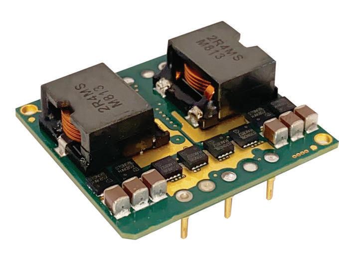
Optimizing the power conversion design has several beneficial second order effects above and beyond the direct impacts highlighted thus far. By using a non-isolated converter, the requirement for a large, heavy ferrite transformer, which contributes to the size and weight of the end-device, is eliminated. In some instances, a non-isolated converter in a 1/16 brick package (34mm x 36.8mm x 11.5mm high) can offer the same amount of power as a 1/4 (58.4 x 22.9 x 8.8mm) or even a 1/2 brick (61 x 57.9 x 12.7mm) isolated converter. With lighter power electronics, the robot will weigh less reducing the motor power required to move the end device. This results in additional energy conservation and helps manage the energy budget mentioned earlier. Non-isolated converters can 0 6 12 18 24 30 Output Current (A) 0 6 12 18 24 30 Output Current (A) 0 6 12 18 24 30 36 36 36 42 42 42 Vin = 24V Vin = 24VOutput Current (A) Vin = 24V
Figure 3: i7A dc-dc converter efficiency profile versus output current.
Figure 4: TDK-Lambda’s i7A 750W dc-dc converter. also have streamlined feedback loops, removing cost, complexity, and some quiescent load from the design.
Summary
The selection of a suitable battery for your next battery powered design is important. It is arguably just as important to optimize the efficiency of the devise’s electronics and power conversion stages, thus maximizing the lifetime of the battery. Special attention should be given to the choice of topology, ensuring that as much of the battery’s output voltage range is utilized as possible, including the conversion from the battery voltage to the associated electronics driving the motor and the associated control and navigation functions.
Consider partnering with an experienced power conversion company to address the needs of your next battery powered design. There are many standard products available and selecting the right product for the application is very important.
www.us.lambda.tdk.com
A 5G forecast for 2023
How small cells will usher in the true power of 5G
BY DR. MARZIEH VEYSEH, CO-FOUNDER & CPO OF SITUNE CORP.
The world’s reliance on cellular networks is undeniable. There are more than 8 billion mobile subscribers globally, and the average monthly data usage per subscriber will increase from 15GB by end of 2022 to 40GB by end of 2027. With the increased demand both in terms of traffic and service quality, the world has been waiting for 5G to fulfill the promises of coverage and excellence. 5G provides faster speeds, greater capacity, better reliability, and lower latency. This is done through advancements in terms of radio access technology with wider bandwidths and higher frequencies as well as the new 5G core architecture with end-to-end network slicing and guaranteed quality of service.
For service providers and the telecommunications industry, 5G deployments are a major and critical undertaking as they strive to increase market share with a more powerful and programmable network. This is done by deploying 5G SA architecture and supporting time-sensitive applications, higher capacity needs, and edge computing.
Advancements in hardware
Unfortunately, improvements have been held back by development issues in radio access network and applications. However, this is about to change in 2023 due to new advancements in hardware technology and ease of deployment of small cells and private networks.
In 2023, we will see the first implementations of 5G that will allow mobile users and enterprises to fully experience the power of the technology at scale. Increases in 5G small cell coverage will come with less cost, easier deployment, and lower energy consumption, prompting applications of 5G including special use cases and critical services.
A small cell is a mini wireless network base station with integrated RF and networking functionalities to provide cellular access to a smaller number of users in an indoor or outdoor setting. They are made to be small, compact, and unobtrusive.
The 5G standard was designed to bring broadband capabilities to the widest possible user base; to bridge the gaps of zero coverage in places like rural areas, or scaling coverage to support massive numbers of users in high-density urban areas. Macrocells are the mainstream choice of deployment, representing high-capacity radio equipment with high power signals that generally stand 200 feet or higher with strict requirements in terms of physical locations and regulatory laws. They are costly and consume hundreds of kilowatts of electricity.
High power macrocells also don’t send reliable signal to all areas. Devices on the edge experience weaker signals. In congested areas, even if the user is not at the edge or in an indoor environment, the growing traffic and data demand leads to slower speed and higher latency, thus limiting the applications.
In the meantime, enterprises and businesses demand large scale data analysis tools where their information is kept secure and safe while the network equipment has the capability to support high traffic communication and utilize 5G enabled application. This simply cannot be done by macrocells.
Recent hardware technology breakthroughs are giving network equipment manufacturers the capability to develop energy efficient and cost-effective small cell equipment with better thermal management, smaller form factors and higher performance. These new, small cells make it possible to extend 5G coverage in hard-to-reach areas. With comprehensive 5G coverage as the goal, in 2023 telecommunication industry and service providers will finally move to deploying small cells in larger volumes.
We will see practical applications of small cells in both the consumer and the business/ enterprise markets in 2023.

SiTune co-founder says we will see practical applications of small cells in both the consumer and the business/enterprise markets in 2023.
Fixed Wireless Access
The first and the fastest way to get 5G to consumers will come in a small box available from your mobile service providers. Over 100 million FWA connections are forecasted by end of 2022. Indoor and outdoor Consumer Premise Equipment (CPE) will become widely available in 2023, beginning in India and parts of the U.S. CPE connections are the best way to extend 5G coverage in areas where cable and fiber installations are not practical.
With the clear advantages of 5G cellular technology over legacy wireless LAN (Wi-Fi), private entities, enterprises and organizations can deploy private cellular network and leverage the benefits in their controlled and secure setting using the new available small cell equipment. The cost and power benefits of the advanced hardware and software solutions make 5G private networks one of the early deployments of 5G.
The radio access equipment over leased licensed bands or unlicensed band (Citizens Broadband Radio Service (CBRS), is a band of radio-frequency spectrum from 3.5GHz to 3.7GHz designated by the FCC for shared use. Edge devices or users need to have access to the allocated band either through subscription or a provided SIM card. This means that a private cellular network includes all the tech and equipment necessary to deploy a functional system.
Beyond 2023
2023 will be the year of small cells. Fixed wireless access and private networks will be the first real taste of the power of 5G. What can we look forward to in 2024? In many ways 2023 is a stepping stone to the future of 5G with its full potential. The implementations we will see will likely happen regionally, dependent on government regulations and access.
On the technology side, many in the industry are looking to O-RAN, or Open Radio Access Network, to change the game in 5G. This will begin to happen in 2024, as service providers upgrade their 5G radio infrastructure with ORAN in mind. ORAN allows providers to virtualize the backhaul, giving them more flexibility to build faster programmable networks, with best-in-class equipment. ORAN is a must to achieve the vision we all want for 5G.
The (lowest) Loss Leaders
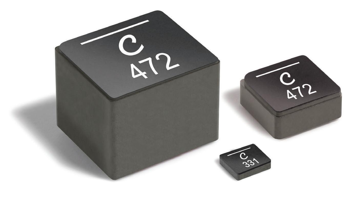
XGL Family power inductors feature the industry’s lowest DC resistance and extremely low AC losses for a wide range of DC-DC converters
Coilcraft’s XGL Family of molded power inductors is available in a wide range of inductance values (from 82 nH to 56 µH) and current ratings up to 117 Amps. With up to 60% lower DCR than previous-generation products, they are the most efficient power inductors available today!
Their ultra-low DCR and higher Irms also allow XGL Family inductors to operate much cooler than other components.
All XGL Family inductors are qualified to AEC-Q200 Grade 1 standards (with a maximum part temperature of 165°C) and have no thermal aging issues, making them ideal for automotive and other harsh environment applications.
Download datasheets and request free samples at www.coilcraft.com/XGL.
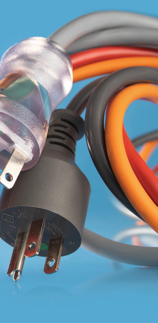
From bare wire to eye-candy resins
US-based cable & cord set maker holds
the line BY INTERPOWER CORP.
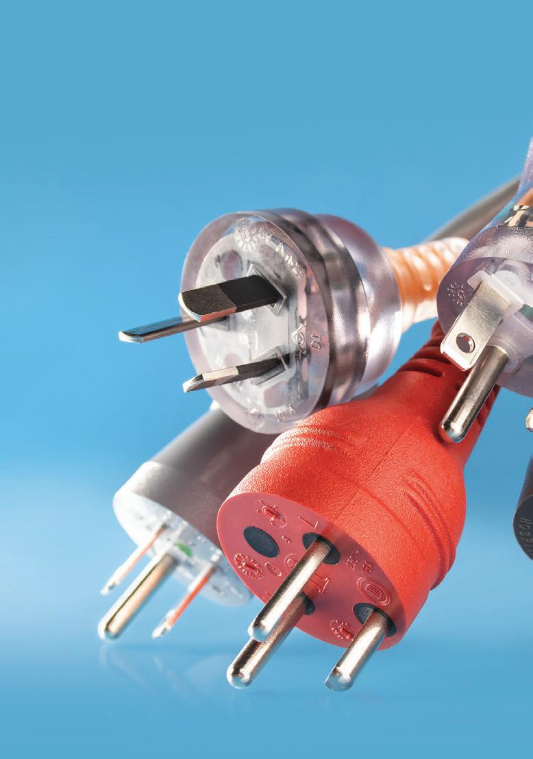
Before cord sets are ready to be boxed for shipping, the colourants used in the resins, and the shiny brass and alloys of blades and pins may often resemble an electrical work of art that catches the eye—especially the orange and red cord sets preferred by Australian and Denmark hospitals respectively. Or maybe it’s a clear molded plug, or a hand-wired plug where one can see inside to tell whether every wire retains electrical continuity around the stainless steel ring that binds the conductors. Even standard colours like black and gray offer a semblance of eye candy while manufactured to carry hundreds of volts to equipment across multiple environments.
These finished electrical products began as reels of copper, pellets of resin, stainless steel or alloy screws and fasteners, folded brass and other alloys, bridges, strands of Kevlar, fuses, and the multiple processes of multiple machines to extrude (insulating and jacketing), cable (in part via a rotating capstan), mold, cut, strip, crimp, ultrasonic weld (metal and plastic), label, hank, and tie. There are also numerous stations along the way just on the extrusion line: multiple laser-measuring stations, a wire-cleaning station, extruders 1-3, a talc station, spark testers, a water-cooling station, and a drying station.
Everyday marvels
Inventions that changed the world are too numerous to list: fire, the wheel, gun powder, the printing press and the steam engine, the pencil and the light bulb, and likely somewhere down the list is the bare copper wire. Copper is an iconic conductor with many great properties—corrosion resistance is high among them, and copper is still a popular conduit for water.
Extrusion line: A magical mystery tour
allows the wire to unspool its hundreds of pounds while keeping square to the extrusion line. The unspooling of cable down the line relies on a tensioner on one end and a take-up or accumulator on the other end to maintain the necessary tension as to complete the extrusion process.
As the bare wire speeds down the line up to 1,000 feet per minute, its diameter is continually measured by multiple readers using lasers integrated with computer hardware and software which measure to 1/10,000 of an inch. The bare copper wire is cleaned along the line before being extruded in resin by extruders 1-3. Extruder 1 contains the natural, light-coloured material while extruders 2 and 3 extrude separate colours such as blue and brown to coat the bulk of natural resin material from extruder 1—colours are alternated from extruder 2 to 3 by turning a switch on the crosshead.
The insulated wire is measured before and after extrusion while ‘hot’ and measured after cooling ‘cold’ once immersed in a water trough via a filtrated chiller. Laser measurements are taken multiple times along the extrusion line to meet worldwide agency standards (diameters).
The various colours designate ground, line, and neutral conductors according to North American, international, and Japanese colours per their agency standards. However, four- and five-conductors may be required for larger cable diameters, requiring even more natural resin from extruder 1 during the jacketing process. The insulated wire maintains agency diameter specifications due to the laser measurements which regulate and adjust in concert with dry and wet capstans, which are vertical drums spinning the cable faster or slower to reduce or add material to meet preprogrammed diameter specifications.
Bare copper is never spark-tested due to the nature of copper and electricity, but once insulated, the wires are spark-tested for holes or gaps in the natural material.
A clear moulded plug lets you see if every wire retains electrical continuity around the ring that binds conductors.
Before being jacketed, the bunched lengthof-lay conductors are coated in talc for easier wire-stripping by the end-user. The cords are then jacketed in natural resin and a single layer of colourant. Jacketed wire (cable)
Once the separate insulated wires spool onto the take-up, the individual spools run through the rotating capstan connected to the cabler, and strands are ‘bunched’ into a length of lay: the length of one coloured wire woven under another coloured wire (visible to the eye) is one definition of the length of lay. The length-of-lay makes the bunched wires more flexible which helps preserve the electrical continuity of its conductors.
Before being jacketed, the bunched length-of-lay conductors are coated in talc (for easier wire-stripping by the customer) before being jacketed in natural resin and a single layer of colourant. Extruder 1 is the workhorse for jacketing since cable requires much more natural resin than colourant to hold the conductors in place while remaining flexible. The single layer of colourant is added onto the cable wall for identification (line, neutral, ground, etc.).
The jacket runs through a printer down the line to receive agency (UL/ CSA/VDE, etc.) file numbers and approval marks, voltage and flammability ratings, jacket material, e.g., ‘SJT’ and sizes in AWG and mm along with the manufacturer. The cable is now ready to be reeled onto a wooden spool where it is wrapped in plastic and properly
labeled. The cable is now ready to be shipped.
Key cable factors already determined
While the above process is used for both North American and international cable, the materials, e.g., resins with certain characteristics according to the environment for which it will be used, will have already been determined before the first foot of cable is manufactured.
If the market is North America, then North American approved cable needs to be used. If in Germany, then international-approved cable must be used. If China, the cable must meet Chinese standards requiring approvals from a Chinese agency—the market where products will be sold (North America, Europe, Asia, or South America) determines the type of cable and agency approvals needed. Typically, countries have their own agencies: the United States (UL), Canada (CSA), and Germany (VDE), to name a few.
Environments for cable use
One main factor in determining cable type is the immediate environment. A household appliance requires a different jacket than a jacket used for industrial use. If used outdoors, one must consider abrasion, heat, and humidity. And there’s no need to rush out and reinvent plastic since UL’s iQ site offers many resin ‘recipes’ already approved, saving manufacturers the cost of sending samples for agency testing unless specialized blends are needed, such as adding unique materials to reinforce polymers or adding UV stabilizers.
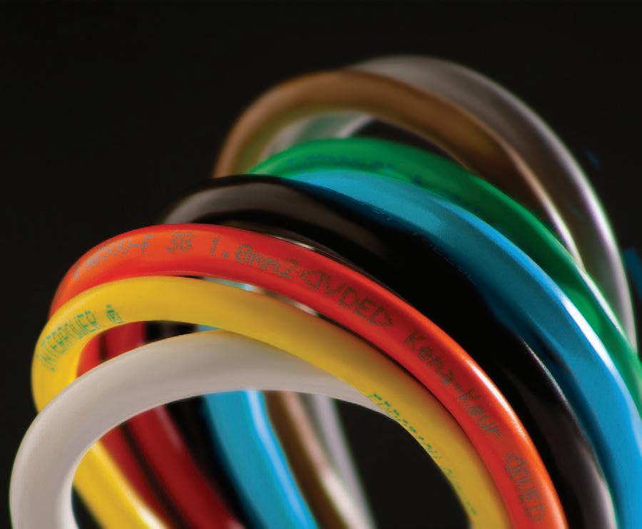
The various colours of the cables designate ground line and neutral conductors according to North American, international and Japanese colours per their agency standards.
North American cable
North American cable is sized in American Wire Gauge (AWG), which uses an inverse relationship to size—the larger the number the smaller the cable. Cable for single-phase applications will be either a 2- or a 3- wire variety. A 2-wire cable is for Class II (ungrounded) applications while 3-wire cable is for Class I applications, which require a ground. Three-phase applications require either a 4- or 5-wire cable.
Basic cabling material Thermoplastic
Thermoplastic can be softened through heating and hardened through cooling. It can be molded when heated and can retain its shape after cooling. Thermoplastic is the opposite of thermoset.
Thermoplastic Elastomer
Thermoplastic or TPE is a material that has characteristics of rubber as well as thermoplastic.
Thermoset
Thermoset uses a heating process— curing—and once the plastic is cured, it can’t be altered from its original state. PVC
PVC is a common thermoplastic material for cable and conductor jackets and some molded plugs.
Rubber
Rubber is also a common material for cable. It is a thermoset-type material. While it may be more costly than thermoplastic cable, rubber is extremely durable. Rubber is a good choice for outdoor applications.
Summary
As global supply chains remain largely unchanged, it’s more important than ever to procure finished goods and raw materials from distributors and production facilities within reasonably close proximities, whether those resources come from neighboring states, provinces, or regions. As U.S. imports continue to decline, more U.S. companies look toward domestic production and partnerships, as well as those in neighboring countries. While many North American and European companies slowly begin to decouple from China, think tanks such as the Foundation for Defense of Democracies believe such a decoupling is inevitable as a long-term strategy.
www.interpower.com
One main factor in determining cable type is the immediate environment.
Interpower Corp. is one of two remaining electrical cord manufacturers in the United States. The firm supplies power system components worldwide.
Voltage, footprint and cooling
The power considerations that dictate data centre design
BY VITO SAVINO, WIRELINE AND DATA CENTER SEGMENT LEADER FOR ABB POWER CONVERSION

As global reliance on data centers grows, so too does their energy consumption. While estimates on data centers’ total worldwide energy consumption vary, it’s generally agreed that the number falls in the range of 1-2% — representing a significant portion of global energy use. No matter what the actual number is, improving efficiency even by a small margin would, at this scale, result in a significant reduction in overall energy use. That’s good for the Earth and operators alike.
With concerns about sustainability and energy efficiency reaching a boiling point worldwide, engineers and power specialists are hard at work developing solutions to make more efficient data centers a reality. Often, these solutions present a paradox: Data center designers and operators are looking for options that both boost power density and improve efficiency. It’s a complex and seemingly contradictory task, but success, it turns out, may hinge on broadening the conversation.
Power density is often viewed as a board-level concern, but that approach limits the potential for density and efficiency improvements at scale. Instead, the conversation must extend beyond boards and components to the power architecture of the facility. By taking a holistic view of power density in a data center — from the utility entrance to the cabinet, the rack to the board — designers can take the necessary steps to mitigate energy loss across the operation.
Voltage and footprint: A delicate balance
When designing the power infrastructure for a data center, efficiency and power density come down to three key factors: footprint, voltage, and cooling. Engineers must balance these factors as they push the limits of optimization to increase power density at both the board and facility levels. Success in this endeavor may hinge on designing for efficiency and density from day one.
Footprint, of course, often becomes a primary consideration as it is relatively inflexible. A printed circuit board (pcb) has a limited amount of space, so making the most of it is crucial – especially as computing needs continue to increase exponentially with continuous technological advancements. Engineers are tasked with packing as much computing capacity as possible into their boards and applications and are cognizant that any unused space on a pcb may be seen as wasted money due to the high perceived cost-per-square-inch. These factors equate to limited space remaining for the required power components. This is one reason power density is at a premium. Power needs increase yet the allotted space in a board or in a system remains the same (or even shrinks). And given the cost and sheer amount of networking equipment in today’s advanced data centers, even minimal board-mounted power density improvements can have wide-reaching impacts.
From an efficiency perspective, one aspect to consider is the operating voltage on the board. Traditionally, the voltages used in data centers at the chip level and along the utility entrance have been on the lower end of the spectrum. Lower-voltage architectures require higher currents – higher currents result in lower efficiency from transfers of energy (i2r losses), especially if sufficient space cannot be afforded to mitigate the issue. To help, board designers are increasing voltages as close to the IT load as possible. Implementing higher-voltage board-level power architectures, such as 48V architectures, can both help improve efficiencies and power densities. The spacing required to avoid arcing at higher voltages, however, is a tradeoff that must be taken into consideration.
Beyond board-level power density, many of the principles we’ve discussed are also relevant at the cabinet and facility level. Keeping power density considerations in mind from the very beginning of the process can help ensure more efficient and cost-effective operation in the future.
Strategies like reducing the number of conversion steps required to provide the precise power needed for networking equipment or implementing high-voltage infrastructure as close to devices as possible can help designers achieve better power usage effectiveness (PuE) throughout a facility. The complex relationships between these factors can make optimization
50%
Data centers only use approximately 50% of their energy to execute computing functions.

challenging, but accounting for them during the initial stages of facility, rack, and board design can help optimize operations.
The cooling paradox
The third factor noted above, cooling, presents another confounding element in data center design. Done correctly, it can improve efficiency, protect equipment, and help boost performance. Done wrong? It can have serious (and costly) repercussions.
Incredibly, data centers only use approximately 50% of their energy to execute computing functions. Of the 50% used for computing, about 98% is used to support IT loads. The remaining 2% is shed as heat in the power conversion process. Of the remaining 50% of energy used, 2540% is typically allocated to HVAC systems to maintain the computer room environment, or to computer room air-conditions.
The scale of the facility and operations exacerbates the issue, making cooling an even more significant consideration for larger, power-hungry data centers. In addition, because cooling elements create their own heat, a system that’s not cooling equipment properly ends up contributing more heat to the overall equation. Building smaller facilities doesn’t solve the issue; packing more computing power into smaller spaces actually compounds the issue further as proximity increases temperatures.
There are several options for cooling data centers — with air conduction, liquid cooling, and geophysical solutions being the most popular. Each has its own benefits and drawbacks. Deciding which is appropriate for a given build is a complex process that should take into consideration the size and location of the facility, its proximity to cold air or water sources, and the equipment within it. Data center power designers and engineers can also benefit from keeping scalability in mind when comparing cooling methods to help ensure any choice they make can accommodate future plans for expansion.
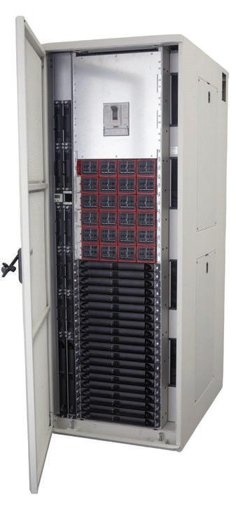
ABB’s robust line of dc-dc bus converters meet the needs of OEMs developing solutions for data centres.
ABB’s Edge data center power architecture is able to meet the demands of data centers. The full picture

As power demands rise and energy use in data centers continuous to increase exponentially to keep pace with evolving networking needs, it’s more critical than ever for power designers and data center operators to view equipment and facilities through a holistic lens. This can help them to better tackle potential energy waste and inefficiencies across equipment and operations on the front end of data center planning. By considering operations as a whole, designers may find ways to boost carbon-reduction initiatives, lower energy consumption, enjoy practical business benefits, and do their part to build a more sustainable future.
www.abbpowerconversion.com
ABB Power Conversion designs and manufactures power solutions for 5G, wireless, data centre, and industrial applications.


For over 20 years, our global customers have counted on us to bring their products to market efficiently and with peace of mind. As your EMS solutions partner in Canada and the USA, we evolve with you to accommodate your specific needs! We are certified and ready to launch your ground-breaking product.
Connect with us and experience the DSM difference!
See what's new at DSM! dynamicsourcemfg.com