10 minute read
WIRELESS WEARABLES
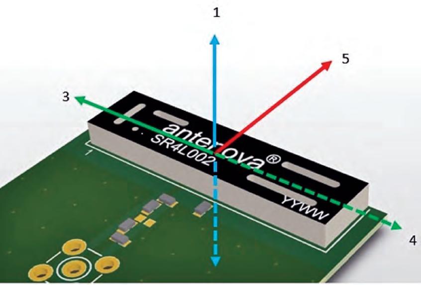
Figure 1 shows how the antenna radiates in six spatial directions. Using chip antennas in pcb design
NB-IoT products are being implemented into many applications, including wearable electronics. BY GEOFF SCHULTEIS AND ROBERT DUMONT
Antennas are effectively transducers, turning electrical energy into radio w aves and back again. This process involves physics, so the laws of physics are at play. While digital and analog components may be placed anywhere you like, with an antenna, its position and operation will impact its performance greatly. For this very reason, it is recommended to think about the antenna first, i.e. selecting an antenna at the early stages of a new product design, so that the antenna design constraints can be considered, and then think about creating a layout that will allow the antenna to perform at its best.
Antenna position on pcb Unlike a digital component, an antenna will not always perform exactly as the specifications quoted on the data sheet. There are several factors that can affect its overall performance, such as: • Length of ground plane • Other components in proximity • Outer casing and its mater ial • P osition within the device • Layout of the pcb (power/noise issues)
With any antenna, it is important to understand how its position will affect its performance. Particularly for an embedded antenna, the device needs to be positioned clearly away from the rest of the circuit – otherwise noise and other components can detune and interfere the component’s perfor mance.
Some antennas perfor m best when positioned on the corner of the pcb. However, there are other antennas that operate best along the long-side edge. The data sheet of each antenna will detail the optimum placement of the antenna, as will the design of the evaluation board.
The greatest design challenge is probably to provide sufficient ground plane length for sub-Gigahertz fre quencies.
How the antenna radiates A chip antenna radiates in six spatial directions and ideally requires clearance in three to five of these, as shown belo w. Where this cannot be achieved it is important to keep as many directions clear as possible, and at least a minimum of three. Where there are fewer directions clear, there will be a degradation of performance.
This is why some antennas perform best on the corner of a circuit board, as this effectively means there are five directions where the antenna can op erate as if it were in free space.
Ground plane Embedded antennas use ground planes on the host pcb in order to radiate efficiently. The ground plane constitutes half of the antenna, so respecting the recommendations provided in the manufacturer’s data sheets is essential, if you are to achieve good levels of radiated performance. In applications that require network certification, following the guidelines in the manufacturers data sheet for the selected antenna is critical.
There are two common configura tions for the ground plane. In some cases, the ground plane extends under the antenna and in others there needs to be ground cleared away under the antenna itself.
NB-IoT products are an interesting area of development right now, with
many new applications in remote-controlled lighting, tracking and wearable electronics . However, the greatest demand is for smaller products, which means the devices must work with shorter ground planes and cannot use too much power.
This presents a dilemma for the designer, because for antennas to op erate at sub-1GHz frequencies, they need g round plane lengths of 100mm or more to prevent antenna efficiency from dropping. If the antenna effi ciency should drop, this will cause issues gaining network approval for the finished product. So, the challenge for the product designer is to create a physical design that meets the limita tions of size and space, and still performs well in operation.
Consideration for ho w the antenna and pcb are incorporated into the overall design may take advantage of being attached to either a wiring har ness and plug such as in OBD2 devices or connecting to a larger device through data I/O and po wer buses extending the electrical ground plane presented to the antenna.
Efficiency
Efficiency is the single most important measure of antenna performance. It descr ibes the portion of radiated power which is supplied to and radiates away from the antenna. In small, battery-powered devices, achieving efficient performance is integral to the longevity of the device.
There are plenty of factors to con sider when examining potential areas to impro ve antenna efficiency. Some of these include: • Resonant frequency shifts caused by reflective or absorptive masses placed near the antenna. • Metallic casing or glass filled n ylon plastic housings near or around an antenna, which will cause a null or depression in the 3D radiated pattern inhibiting radiation in the direction of the null. • Nearby antennas with similar frequencies which may detune one another’s near-fields. We recommend that they should be isolated up to -10dB <1GHz and -20dB for 2GHz as a minimum goal.
RF Modules Like SMD antennas, modules are complete antenna solutions which can be placed directly on the pcb. The advantage these have over standard surface-mounted antennas is that they come pre-assembled. The antenna will already have a chip and other key components.
These work well for GNSS applica tions. They effectively offer a ‘drop-in’

solution, which means that designers do not need to spend time designing in complex RF circuitry.
Outer casing Having considered the antenna’s position on the pcb, it is also important to think about the outer casing for the device. Metal is not conducive to effective antenna performance. Conductive surfaces become charged when in contact with electromagnetic
NB-IoT products are an interesting area of development right now, with many new applications in remotecontrolled lighting, tracking and wearable electronics. However, the greatest demand is for smaller products, which means the devices must work with shorter ground planes and cannot use too much power
fields and become radiators. This causes a range of issues for effective antenna performance.
It is also important to consider the gap between the casing or housing and the antenna. Plastic has a higher dielectric constant than air, so plac ing an antenna too close to a plastic co ver is also likely to detune the signals.
Tips for antenna integration
Some tips for successful integration of a chip antenna: 1. Select an appropriate ground plane length for the lowest frequency of the antenna. 2.If the antenna is ground plane free, make sure that all the pcb layers under the antenna are free, and that no metallic objects such as a battery or LCD are placed beneath it. 3. Never run digital traces underneath the antenna or wires above/below it. 4. Respect the ground plane clearance shown in the datasheet. 5. Never use narrow traces or unnec essarily long transmission lines. 6 . Some antennas need to be placed in the pcb corner, whilst others are to be placed along the long edge of the pcb; find an antenna which inte grates seamlessly within your design. 7 . Do not place large or noisy highspeed switching components nearby.
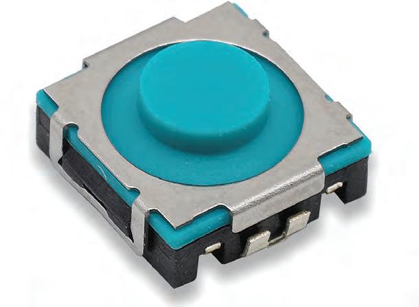
SOFT FEEDBACK TACT SWITCH COMES WITH ULTRA-LOW SOUND VERSION C&K Tact Low Sound (TLS) Series of tactile switches include a low sound, long travel and positive tactile feedback version. Devices provide advanced haptic communication with ultra-soft feedback that can be customized to meet vehicle interior requirements. Compact device with J leads gives designers flexibility to reduce the size of the printed circuit board, or add functionality to the design. The IP54 sealed product offers protection against dust, liquid and humidity. www.ckswitches.com/products/ switches/product-details/Tactile/ TLS/

TEMPERATURE SENSOR IS SMALL, ACCURATE AND VERSATILE WURTH ELEKTRONIK
output data rates up to a maximum of 200Hz. www.we-online.com/catalog/ en/WSEN-TIDS/
PROGRAMMABLE SMART SENSOR IS ALL-IN-ONE BOSCH BHI260AB all-in-one programmable smart sensor combines an accelerometer, gyroscope and fusion softw are, allowing a flexible environment for the development of sensorbased applications. This softw are development kit includes Sensortec’s programmable 32-bit microcontroller (Fuser2), a leading-edge 6-axis Inertial Measurement Unit (IMU) and a powerful software framework containing pre-installed sensor fusion and other sensor processing software, all within a small 44 pad LGA package. www.bosch-sensortec.com/
WSEN-TIDS temperature sensor measures 2.0 x 2.0 x 0.5mm, suitable for a wide application range. Accuracy of device’s measuring range is -40 to 125°C is ±0.5°C, while in the range -10 to 60°C it goes down to ±0.25°C. Device is factory calibrated and can be used without time-consuming re-measurements. Device’s 16-bit output signal can be read out via an I²C interface with different


SMALL LINEAR THERMISTORS BOOST THERMAL LIMITS TEXAS INSTRUMENTS Linear thermistors deliver up to 50% higher accuracy than negative temperature coefficient (NTC) thermistors, enabling operation closer to the thermal limits of the other components and the overall system. Devices maximize performance, while reducing bill-of-materials (BOM) and minimize design time. Devices deliver reliable, highly accurate thermal measurements, particularly at temperatures above 80°C. Suitable for industrial, automotive and consumer applications where precise, real-time temperature readings are fundamental to system performance and protection. www.ti.com/thermistors-pr
COMPACT RIGHT ANGLE TACT SWITCH IS RATED IP67 E-SWITCH TL6340 right angle surface mount tact switch comes with a compact size of 2.90mm (W) x 3.85mm (L) x 2.00mm (H), suitable for product designs with limited pcb space. Devices provide SPST contact arrangement, 12Vdc, 20mA contact rating, up to 200,000 cycle life expectancy, operating and storage temperature of -40°C to +85°C, 0.2mm travel and actuation force of 160gf. With an IP67 rating for moisture and dust protection, devices are suitable for a variety of applications. www.e-switch.com
MCUS WITH ARM CORTEX-M CORE ENHANCE BLUETOOTH 5.0 SECURITY RENESAS

Single-chip RA4W1 RA microcontroller (MCU) with an integrated Bluetooth 5.0 Low Energy radio includes a 48MHz, 32-bit Arm Cortex-M4 core and Bluetooth 5.0 core delivered in a 56-pin QFN package. Together, MCU and easy-to-use Flexible Software Package (FSP) enables engineers to immediately begin development with Arm ecosystem software and hardware building blocks that work out-of-the-box with RA MCUs. Device makes it easy for embedded designers to develop safe and secure IoT endpoint devices for Industry 4.0. www.renesas.com/us/en/ products/microcontrollers-microprocessors/ra/ra4/ra4w1.html
TAILOR-MADE SUPERJUNCTION MOSFET PERFORM IN AUTOMOTIVE DESIGNS INFINEON TECHNOLOGIES
CoolMOS CFD7A series silicon-based, high-performance tailor-made superjunction MOSFET can be used in both the PFC and the dc-dc stage of on-board charger systems and HV-LV dc-dc converters specifically optimized for electric-vehicle applications. Device is fully compatible with system voltages up to 475 VDC. Higher efficiency levels are made possible by the Kelvin-source concept reaching peak efficiency levels up to 98.4% measured. www.infineon.com/cfd7a
ULTRA-TINY MOSFETS ARE 36% SMALLER WITH LOW RDS(ON) NEXPERIA
PMH family of ultra-small DFN0606-packaged MOSFETs for mobile and portable applications including wearables offer low RDS(on) for its size and employ the commonly used pitch of 0.35 mm to simplify pcb assembly processes. With a footprint of just 0.62 x 0.62 mm, devices deliver a space-saving of more than 36% when compared to previous-generation DFN1006 parts. Devices deliver improved ESD performance and VGS low voltage threshold down to 0.7 V. www.nexperia.com

The Smart Choice for Small Spaces

Coilcraft is the brand engineers trust most when specifying tiny inductors for compact devices
Boost the performance and battery life of your smallest designs with these tiny RF and power inductors from Coilcraft: • Wirewound chip inductors as small as 0201 size for wireless communications • Shielded power inductors as thin as 0.71 mm for power management • Coupled inductors as small as 2.2 x 1.45 mm for LED display drivers
You can get started by using our suite of web tools to quickly locate the perfect inductors for your design. Compare and analyze multiple parts based on your true operating conditions, and then order free evaluation samples with just a click.
Learn why we’re the biggest name in ultra-miniature inductors. Visit us at www.coilcraft.com.


