
17 minute read
NEXT GEN AVIONICS
Next Gen avionics: from aircraft to spaceship
High data speeds, miniaturization and improved functionality place new demands on connectivity & infrastructure. BY ASTUTE ELECTRONICS LTD.
Aviation’s reliance on data to make critical flying decisions increases year on year. The latest aircraft designs no w entering fleets are equipped with technologies that can deliver unprecedented collection and transmission of data. Though thousands of sensors and sophis ticated digitised systems, the latest generation of aircraft collects enormous amounts of data. By 2026, new fleets could generate 98 million terabytes annually, according to a 2016 estimate by Oliver Wyman – that’s a whopping 5-8 terabytes per flight!
Top: AlexeyPetrov - Getty Images/iStockphoto Left: vahmg - stock.adobe.com The ‘flying data-centres’ analogy has a lot of truth We cannot underestimate the critical importance of this data. For a stark reminder of the trust we place in autonomous avionics we need look no further than the tragic Boeing 737 Max crashes that killed 346 people in all, and eventually prompted the ground ing of all 737 Max planes across the world. Investigations suggest that sensors may have been feeding incorrect data to the MCAS (Maneuvering Charac teristics Augmentation System), leading to a series of events that put the plane into a nosedive. Challenges of Avionics Design What’s driving the rise in data? Virtually everything on board is now directly controlled by, or has a related dependency on electronics. Complex electronic systems throughout aircraft, satellites and spacecraft are de signed by specialist avionics eng ineers (a blend of aviation and electronics) to control engine management, communications, navigation and the multitude of systems that perform individual functions – information displays, passenger comfor t & entertainment, collision avoidance, fuel systems, fli ght recorders, weapons guidance... a truly dizzying array. There are enor mous challenges in avionics design, both environmental and technological. From scorching deser ts to cryogenic atmospheres and lightning stor ms, through sandstorms and dust clouds to explosions, shocks and extreme vibration, these systems must be fully rug gedized. As if surviving some of the toughest field conditions on the planet – and beyond – aren’t enough, avionics engineers are demanding smaller and lighter components that can be mount ed in higher densities, consume less po wer, generate less heat and are standardised for maximum interoperability and service life. Secur ity presents a further challenge. Electronics are typically the most sensitive pieces of equipment on board and may need added protection against disruption from cyber attacks and electronic countermeasures Fig 1. The modern airliner flight deck where virtually everything on board is directly controlled by electronics.. Fig 2. Environmental & technological challenges exist in avionics design
(ECM), ranging from radar jamming and deception to a devastating electromagnetic pulse (EMP) attack. One area of avionics design that is sometimes overlooked is the role of connectors. Elec tronics engineers need to be aw are of how greater functionality, higher data speeds, miniaturisation and ruggedization for har sh environments are impacting on the connectivity and infrastructure in the next generation of avionics . As a franchised distributor, Astute Electronics not only offers a huge range of connectors de signed for the aviation and aerospace industry but works closely with manuf acturers in what is actually a highly complex area.

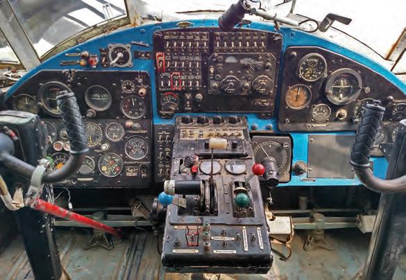
Cockpit Evolution: Aircraft to Spacecraft Pilots who have been flying for several decades have witnessed a gradual but dramatic evolution in cockpit design, as data-driven avionics systems take over many of the functions. The cockpit of today’s airliner looks like science fiction when compared to those of a generation ago. Pilots are no longer faced with a sea of circu lar dials, and are much more likely to use a small number of multi-function displays (MFD). (Fig. 1)
This trend has been driven by the demands of military aviation. Third generation fighter aircraft such as the F-4 Phantom still use mechanical gauges to present information to the pilot. In the 1970s the fourth generation fighter began to take over. At the same time, the increased use of electronic warfare was demand ing new and complicated systems be introduced. The designers of aircraft like the F-16 Fighting Falcon and the F-18 Hornet had to find ways for these new capa bilities to be controlled by a single pilot. This simply could not be achiev ed with conventional dials. (Fig. 3)
Thus was born the multi-func tion display. By condensing a huge amount of infor mation into a simple, easily understood picture, pilots could spend more time concentrating on their role of flying the aircraft rather than managing electronic systems.
Fig 3. Designers of fighter aircraft had to find ways for its capabilities to be controlled by a single pilot.
Fig 4. A lot of computing power is required behind the cockpit screens.
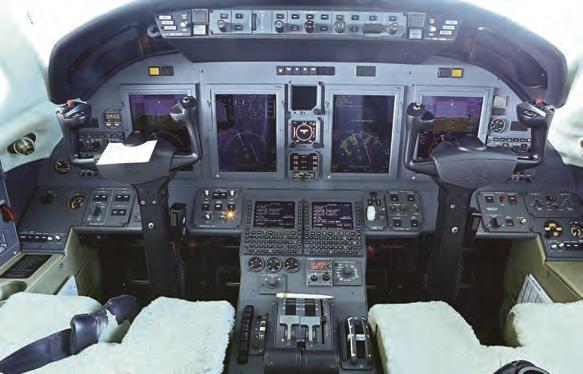
At the same time, the head-up display (HUD) was reaching ma turity. This is a device which takes th e same combined information that might be shown on an MFD, and projects it onto a glass screen in the direct eye-line of the pilot. Suddenly, pilots could fly their aircraft with their “heads up” – looking out of the aircraft – in stead of “heads down”, managing a huge ar ray of dials, switches and controls. (Fig. 2)
You can imagine that, behind the screens, a huge amount of computing power was required to gather, combine and then present this information instantly to the pilot, and you would be correct. If we look forward to the pres ent day the MFD has become a standard tool, not just for fighter pilots but in commercial and even in general aviation. The latest Boeing airliners are fitted with a HUD for each pilot, and the latest Cessna aircraft – de signed for private pilots – are fitted with full-colour, programmable multi-function displays. Head-up displays are ev en available for cars now, showing quite how far this technology has spread. (Fig. 4)
The problem of connectivity remains, however. Such fantas tic displays must combine inputs from such sources as eng ine management systems, the airframe (speed, altitude and attitude), and the latest GPS navigation systems. Each of these connections must per form without fault in an environment that is subject to vibration, acceleration and extremes of temperature. Failure could have life-threatening consequences.
Cockpit displays have come a long way in 50 years, and engi neers need to be aware of the c hallenges that the latest technologies present. High data speeds, miniaturisation and improved functionality make new and interesting demands of the connectivity and infrastruc ture in the next generation of aviation electronics . The latest families of connectors are ready and able to take up those chal lenges.
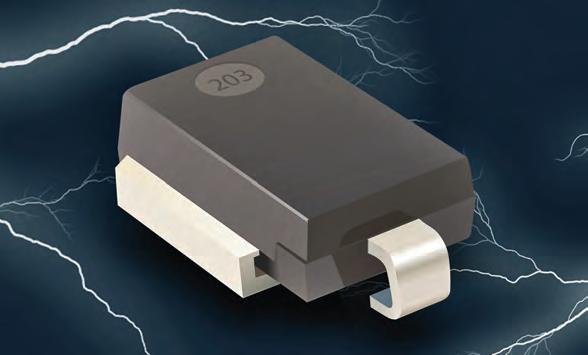
TVS DIODES BOOST POWER, CURRENT RATINGS BOURNS Model 15KPA-SD-Q series transient voltage suppressor (TVS) diodes are for use in dc bus clamping applications and protect sensitive electronics applications against overvoltage transients. Devices are AEC-Q101- compliant making them suitable protection solutions for applications that require high reliability. Device boosts performance from its high peak pulse power (10/1000μs) rating of 15kW and high peak pulse current (8/20μs) rating of 1kA.
www.bourns.com/products/ diodes/diodes-aec-q101-compliant
PIEZO DRIVER CHIP ADVANCES REALISTIC HAPTIC FEEDBACK BOREAS TECHNOLOGIES BOS1211, the first low-power high-voltage piezoelectric driver integrated circuit (IC) enables high-definition (HD) haptic feedback in automotive human machine interfaces (HMIs), such as automotive infotainment screens and safety alerts in touch-sensitive steering wheels. Designed to support TDK Electronics’ family of 120V PowerHap piezo actuators —device is critical to satisfying growing demand for clear tactile feedback in automotive environments. Device is based on form’s patented CapDrive technology, a proprietary scalable piezo driver architecture that provides the foundation for its haptic chips. CapDrive delivers the advantages of piezoelectric material to the
designer: greater energy efficiency, low heat dissipation and rapid response times.
www.boreas.ca/pages/capdrive-technology
METALLIZED POLYPROPYLENE FILM CAPACITORS SERVE EV TECHNOLOGY KEMET R41T and R76H series AEC-Q200 qualified metallized polypropylene film capacitors address the stringent requirements of the latest automotive applications, including those for electric vehicle (EV) powertrains and Advanced Driver Assistance Systems (ADAS). Devices have a 125ºC maximum operating temperature and exceeds the requirements of 85ºC/85% relative humidity temperature-bias-humidity tests. Devices support the design of high-performance, high-reliability circuits including those based on Wide Band Gap (WBG) semiconductor solutions.
www.kemet.com/film
RELAYS MEET STRINGENT IEC62752 REQUIREMENTS AMERICAN ZETTLER AZEV116 and AZEV132 series of relays meet stringent requirements of IEC62752 for Mode 2 charging of Electric Vehicles (EV). For the charging of electric vehicles using household or CEE sockets, the IEC62752 standard offers system designers a welcome sense of clarity on what future regulations are likely to require. Charge mode 2 (Level 2 charging / IC-CPD) addresses necessary control and safety
requirements for charging cables along with considerations for the type of currents and service life these products will endure. Devices also have an isolated signal monitoring contact to allow detection of any possible welding issues with the main contacts. www.azettler.com
SAFE, SECURE AUTOMOTIVE ETHERNET SWITCH SERVES TSN NXP SEMICONDUCTORS NXP SJA1110 multi-gigabit Ethernet switch is designed to help automakers deliver the high-speed networks required for evolving connected
vehicles. Device provides safety capabilities built in, delivering integrated 100BASE-T1 PHYs, hardware-assisted security, as well as multi-gigabit interfaces. Optimized for integration with firm’s S32G vehicle network processor, device is also part of an overall networking solution which includes the VR5510 power management IC. www.nxp.com
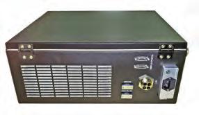
PC MEETS MILITARY STANDARDS FOR CRITICAL SHIELDING EQUIPTO ELECTRONICS TEMPEST PC concept allows customers to choose an up-to-date ATX motherboard, or an HP or Dell i7 PC repackaged for the ultimate in secure operation. The system delivered will be certified to the strictest standard in the industry for devices operating in NATO Zone 0 environment, the NATO SDIP-27 Level A. Each system is fully customizable and typically includes (but not limited to) an Intel i7 processor, ATX motherboard to your specifications, 32 GB memory, storage options, latest Windows operating system, USB 3.0 ports, a card reader for extra security, fiber port options, DB9/DB37 connectors, and high-performance power line filter. The system measures: 18.50” high x 6.65” wide x 17.50” deep. www.equiptoelec.com
TOF DEMO BOARD DRIVES LASERS WITH CURRENTS UP TO 28A EPC
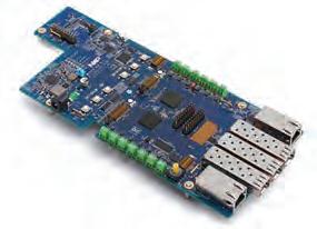
EPC9144 15V, 28 high current pulsed laser diode driver demonstration board is suitable for use in time-offlight systems, where speed and accuracy of object detection is critical. Board demonstrates the rapid transition capability of the AEC Q101-qualified EPC2216 provides power pulses to drive laser diodes, VCSELs or LEDs up to ten times faster than an equivalent MOSFET, in a small fraction of the area, energy, and cost. eGaN FETs and integrated circuits provide the high current pulses, extremely narrow pulse widths, and small size that make affordable, high performance lidar possible..
https://epc-co.com/epc

SHORTWAVE IR CAMERA HAS NO ITAR RESTRICTIONS PRINCETON INFRARED TECH MVCam series shortwave-infrared (SWIR) and visible, compact camera supports the highest commercially-available frame rate at megapixel resolution with no ITAR restrictions. The megapixel indium gallium arsenide (InGaAs) product provides 1280 x 1024 resolution SWIR imagery at up to 95 frames per second (fps), with higher frame rates for user-selectable regions of interest (ROI). At 12µm pixel pitch, the unit’s InGaAs image sensor yields low dark current and high quantum efficiency, providing sensitivity across the SWIR and visible wavelength bands from 0.4 to 1.7µm. www.princetonirtech.com
Canada’s Leading Electronics Market Resource.


COMING UP IN
Advertising in EP&T has been a game changer for our business. The amount of leads generated, which we were able to turn into new customer relationships, is the reason we look to EP&T when debuting new products. The team at EP&T is always professional and responsive, and we couldn’t be happier with the results. US Grant Technologies “ “


MAY ISSUE: Medical Electronics
Tech Update Newsletters: May 11 – Switches & Circuit Protection May 25 – Power Management
JUNE ISSUE: Wearables/Textiles
Tech Update Newsletters: June 8 – Medical Electronics June 15 – Enclosures June 22 – Test & Measurement
CONTACT:
The secrets of position sensing for autonomous vehicles BY MICHAEL MURRAY

There are many big trends in the technology space. Among the most interesting is development of autonomous vehicles. In addition to autonomous car s, buses and trucks, autonomous vehicles also include delivery robots used in warehouses, industrial complexes, large business facilities as well as “last mile” autono mous vehicles and drones used to deliv er meals, medicine and smaller packages.
However, as autonomous cars are gathering the most industry interest and investment, let’s start there.
Fully autonomous (Level 5) driving vehicles are still a number of years away from full production, and more importantly, adoption. However, the adoption rate for autonomous vehi cles is gaining traction due to ongoing adv ancements in sensing, computing and connecting infrastructure and policies required to operate such vehi cles in a ubiquitous and democratized en vironment. There are actually two main systems of classification for the levels of autonomous v ehicles: the National Highway Safety Administration (NHTSA) divides the continuum of autonomy into five levels, while the Society of Automotive Engineers (SAE) divides them into six.
The SAE and NHTSA scales are fairly similar. For example, the bestknown car currently for sale with an appreciable level of autonomy, the Tesla Model S’ Autopilot, happens to fall on the same level in both scales, Level 2.
What is needed for next gen autonomous vehicles? The success of autonomous vehicles is based upon solving the needs for fast response time, precision and long term calibration over time, tempera ture and use. P erhaps, the largest gating item to the adoption rates of autonomous vehicles is that the costs and commis sioning of these systems remains high.
The adoption rate for autonomous vehicles is gaining traction due to ongoing advancements in sensing, computing and connecting infrastructure... To succeed, autonomous vehicles must deliver fast response time, precision and long term calibration over time, temperature and use.
Fur thermore, some technologies like LIDAR remain difficult to use, commission, and esthetically unappealing for consumer s. Consumers will surely push back against the ungainly appearance of LIDAR devices on their car roof , windows and outside mirrors. In addition, ongoing maintenance and repair will need to be f actored in. Environmental challenges such as snow, smog and dust will surely have a corrosive impact upon external LiDAR modules. In spite of those issues, investment into technologies like LIDAR have dominated the headlines in recent years while folks like Tesla’s Elon Musk maintained that LIDAR is not needed and vision systems coupled to inertial measurement units (IMU’s) for GPS and GPS denied applications will persist and grow.
I believe this to be true for many autonomous applications, but not all however.
Where did autonomous begin? You might find this surprising but agricultural equipment – tractors and combines – were among the first commercial uses of vehicle autonomy. Ov er the last decades, the market acceptance and technical advancements within autonomous vehicles on the ground have been aggressive.
Worldwide, manufacturers of smart agriculture, heavy construction equipment and last mile delivery vehi cles are demanding higher levels of accurac y from their embedded GNSS and INS sensor systems, the systems need to be as accurate as possible to ensure highly accurate positioning and accuracy, as well as to ensure safety of human operators and nearby workers.
In addition to the sensors that mea sure positioning relative to signals from the GNSS and GPS satellite networks, there is a lesser-known, but equally critical, sensing technology. We are speaking of Inertial Mea surement Unit (IMU) sensors. Within most positioning systems there is an IMU that helps the positioning engine calculate the position using the physical motion as part of the positioning calculation. This is critical for highly accurate systems which calculate the force, angular rate and orientation of
the system over time and temperature changes. IMU’s are used in man y GPS, GNSS and INS systems and provide absolute heading, positioning and dead reckoning. The backbone to any good IMU is the performance of the system measured by the Allan Deviation of the sensor specifically, the bias stability and Angle Random Walk of the Gyroscope.
Solving the ‘Stiction’ Issues Micro electrical mechanical systems (MEMS) sensors have an inherent stiction issue in which the microscopic silicon fingers of the accelerometer and gyroscope structure can get stuck together. Usually caused by a shock or high acceleration event, once stuck together they can be very difficult to separate due to a phenomenon known as the Van der Waals force. This poses a significant issue for func tionally safe applications and ASIL B rated applications . One way to solve this problem is by using triple redundant sensors embedded within the IMU. If one sensor fails because of stic tion, the other two will continue to function and will keep the vehicle on its path.
The reason bias instability and ARW are important can be ex plained thusly - An autonomous v ehicle driving from one point to another in a perfect straight line will drift over time by the bias stability rating of the IMU. If the IMU is rated at 6 degrees, per hour of bias stability, the car will arrive potentially 6 degrees from the straight line on either side which would equate to 6-8 feet of inaccuracies.
Said differently, if an autono mous vehicle attempted to pass through the Holland Tunnel in New York City using a 6 Degree per hour IMU, it will likely not make it…
On their own, Automotive GPS receivers cannot provide highly accurate continuous posi tion information. With optimal reception from a few dozen global satellites, the GPS receiver can calculate its position to within a few meters. By also including correction signals to correct sat ellite clock errors and atmospheric distortion, the GPS receiver can calculate position to around 2cm to 4cm using algorithmic techniques such as Real-Time Kinematics (RTK). The c alculations take time to perform so the update rate for the GPS receivers is typically about 1Hz or once a second but it can be as fast as 10Hz to 20Hz for more dynamic applications. At high way speeds and under optimal conditions, the vehicle can move 10 ft. or so between GPS updates under optimal conditions.
Currently, highly precise and expensive IMU’s are used in many highly precise applications ranging from missiles, commer cial aircraft to UAV controls and navigation applications . The gating items for higher performance IMU’s in automo tive applications has been threefold. Cost has been prohibitive for v ehicles manufacturers to adopt higher performance IMU’s for autonomous applica tions. E ven though IMU’s are already in vehicles for navigation, roll o ver detection and air bag controls, the performance levels of these class of IMU devices will not solve the problem of dead reckoning in a major tunnel or in vision impaired instances, that are prolonged, and not well sup ported by cameras in white out conditions due to heavy snowfall and fog along with sun saturations issues. As perfor mance needs increase for autonomy, the demand for functionally safe devices also in creases, while at the same time, the quest for lo w costs increases almost linearly.
Big picture, autonomy is en abling wonderful advancements in vehicles, UAV’s and last mile delivery robots that which will help reduce our carbon foot print, increase efficiencies and productivity while hopefully saving lives. Yes, there are challenges to be met – however, using technology cur rently on the market, as well as new and evolving sensing technologies, one day , within a decade or so, autonomous vehicles will be able safely on our highw ays and in our urban centers.
PROTOCASE

Professional, Low Volume CNC MACHINING

Contact Us Today!


