
57 minute read
INDUSTRY NEWS


BUILT GREEN LAUNCHES NET ZERO ENERGY+ PROGRAM Built Green Canada, a certification program that offers residential building courses that encourage more energy efficient building practices, has launched its Net Zero Energy+ program for single family new homes.
The Built Green certification program has a presence in five provinces (B.C., Alberta, Saskatchewan, Manitoba and Ontario), and the organization is committed to guiding improvement through its four certification levels (bronze, silver, gold and platinum) each with increased energy performance requirements.
The launch of its Net Zero Energy+ program adds another level of achievement (Net Zero), and while focused on Net Zero, it takes a holistic approach that goes beyond energy.
In addition to advanced envelope and MCAC ELECTS NEW PRESIDENT, ANNOUNCES 2022 CONFERENCE During another virtual annual general meeting in December, 2021, the Mechanical Contractors Association of Canada (MCAC) announced Wayne Davidson, of Davidson Bros. Mechanical Contractors (Burnaby, B.C.), will serve as president of MCAC for 2021/22 year. Davidson follows Dave Holek of Lekter Industrial/Mechanical Services (Belle River, ON) who served two consecutive terms as MCAC president to maintain consistency through the pandemic.
MCAC has also announced its 2022 conference will be held in person, September 28-October 1 in Halifax. mcac.ca
Wayne Davidson
mechanical system content, the course includes discussion on how occupant behaviour impacts the overall energy use in a house and affects the sizing of renewable energy systems.
The training has seven modules, takes an estimated 20 hours to complete and is a partnership between Built Green Canada and Blue House Energy.
“This course was created in anticipation of what builders will need to know and do, before Net Zero building code changes come into effect,” said Shawna Henderson, CEO of Blue House Energy in a media release. “Our self-directed (on-demand), interactive training model has proven to be a great fit for busy industry pros, so we’re excited to offer this course on another critical topic.” builtgreencanada.ca
UL 60335-2-40 RECERTIFICATION
The biggest change coming to the HVAC industry is recertification to UL 60335-2-40. Intertek can help manufacturers during the transition period.
FOR MORE INFORMATION
+1 800 WORLDLAB (967 5352)
icenter@intertek.com
Intertek.com/HVACR ACTION FURNACE ACQUIRES DIRECT ENERGY ALBERTA HOME SERVICES BUSINESSES Action Furnace has purchased Direct Energy Alberta Home Services businesses from Texas-based NRG Energy.
The new acquisition adds over 40 HVAC experts to the Action Furnace teams in Calgary and Edmonton, along with 5,000 membership customers and a database of over 50,000 customers.
“The Direct Energy Alberta Home Services businesses are a perfect fit for Action Furnace,” said Bruce Sittler, president of Action Furnace.
Complete integration of the Direct Energy Alberta Home Services businesses into Action Furnace is expected by late Spring 2022. actionfurnace.ca <>

HVAC SUPPLY CHAIN:

Wounded, But Still a Marvel
Taking a step back to explore how we got here and what may lie ahead. BY IAN McTEER
HVAC wholesale suppliers, for as long as I can remember, featured well-stocked shelves, informative product displays, friendly and knowledgeable staff, and rarely would anyone leave a wholesaler without the item he or she came to purchase.
Yes, the odd time a part would be out of stock generating a backorder, and sometimes even longer than expected lead times for vital replacement parts would happen as well, often stretching ancient loyalties to the breaking point. That being said, it’s not always about the cost of goods that motivate contractors to deal with one or more wholesalers. Going the extra mile, finding a way to solve a backorder, suggesting alternative products, technical assistance, prompt deliveries and more, these are supply chain activities so important to our industry and ultimately our customers.
IT COMES FROM SOMEWHERE
I could argue that a global supply chain connecting the world is a good thing. Others might say the loss of jobs and disruption to Canada’s manufacturing industry has taken too big a toll on workers. This is not the proper forum to discuss such a topic, however, regardless of where something is made, some parts or components will necessarily have to come from somewhere else.
Thus, the dictionary defines it this way: “a supply chain is a system of organizations, people, activities, information and resources involved in supplying a product or service to a consumer. Supply chain activities involve the transformation of natural resources, raw materials, and components into a finished product then delivered to the end customer.”
How even one of the copper fittings like those on the shelf in the photo above on page 11 gets from a mine in South America to the shelf in that particular store is a journey of incredible complexity encompassing dozens of manufacturing steps, transportation by ocean, air and truck, not to mention human handling and processing every step of the way. The availability of all those goods is a tribute to human ingenuity, something I often simply took for granted.
I am certain this story is well known by everyone—since we’ve all lived it—but a brief synopsis might help to explain where we are and where we might be going from here.
In late 2019 a flu pandemic hit the entire world, something like the Spanish Flu pandemic of 1918 although not as deadly. Rightly or wrongly, many governments across the globe decided to lockdown their economies, a move originally conceived to be a two-week effort to “flatten the curve,” thus preventing an out-of-control uptick of new flu cases that might overwhelm each nation’s healthcare infrastructure.
Many workers were furloughed, laid off, or sent to work from home. With governments chipping in by offering extended unemployment benefits and other financial supports, those at home decided to start spending money on just about everything, from electronics to home renovations.
One of the first commodities to feel the pinch was pressure treated lumber, as many new decks and other outdoor improvement projects quickly emptied lumber yards. High prices for limited lumber inventories have even persisted to this day.
Once vaccines became available and lockdowns were lifted in many places, both the U.S. and Canadian economies started to recover. People continued buying things, all sorts of things, large numbers of these things coming from abroad, especially from China, Vietnam, Thailand and India.
Many HVAC contractors reported sales in 2020 and the first half of 2021 to be their best ever. Yet, at the same time, expanding equipment and service sales in the HVAC industry, normally a good thing, created untold levels of stress and frustration for contractors, their employees and customers alike. Just like Alice mused while in Wonderland: “It would be so nice if something made sense for a change.”
Data from the Heating, Refrigeration and Air Conditioning Institute of Canada (HRAI) showing shipments into the Canadian HVAC supply chain as of the third quarter, October 2021, suggests there’s a buying frenzy going on forcing wholesalers to stock up. I can’t remember such a boom in residential air conditioning shipments at 132% over the previous year and ductless split systems were up 62%.
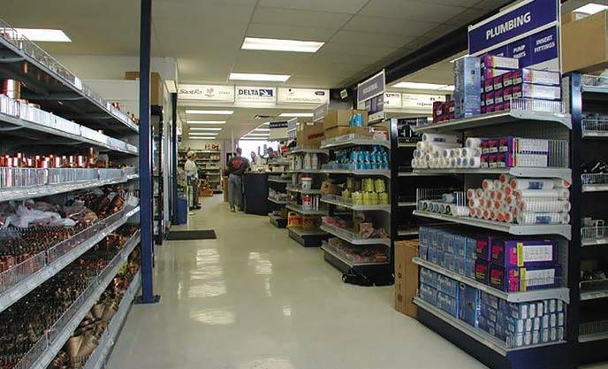
This well stocked self service area of a typical wholesale supply house contains all the items contractors need every day. Ultimately, this photo describes much of what it takes to keep Canada’s infrastructure in top condition.
SUPPLY CHAIN – PEOPLE
Regardless of what robots can do for various industries (and it’s a lot), plenty of humans must also participate at every link in the complex supply chain, too. Businesses large and small, looking to get back to work, found themselves unable to attract laid-off workers back into the fold or even attract new employees—even with higher wages and better benefits.
Figures from the U.S. last July show that more than 11 million jobs remained unfilled. Vaccine mandates haven’t helped, with many workers refusing to take the “jab.”
Once again, states and provinces resurrected lockdown procedures of varying degrees as the Delta and then Omicron variants worked their way through the population. Industries deemed to be essential continue to operate, however, staff shortages (lockdown or not) take a toll on productivity. It seems every industry is calling out for new or replacement staff. Personnel shortages in our industry have been around well before COVID came along, but the demand for staff including installers, technicians, managers, system designers, equipment salespeople, distribution and warehousing material handlers is becoming more acute every day.
SUPPLY CHAIN – COMPONENTS
Should any of the components used in products like a heat pump become unavailable, the manufacturer might be able to source alternate components from elsewhere. Sometimes, missing items could be sub-assemblies built by another company and shipped to the main assembly plant on a just in time (JIT) basis.
Sub-assemblies will often be things like pre-made wiring harnesses with plugs and connectors attached or entire component electrical boxes.
Even one missing component or subassembly can shut down an assembly line. Manufacturing methods pioneered by the Japanese decades ago saw major North American manufacturers adopting the principle of JIT instead of warehousing parts and pieces meant Continued on p12
for the assembly line. A considerable amount of Canada’s warehouse space exists in truck trailers on the move over our highways at any given time.
An integral part of many modern HVAC products, the almighty microprocessor brain (or chip), has been one of the most difficult components to source since the early days of the pandemic. Several fires at Renesas Electronics in Japan, the worst one in March 2021, created a huge gap in the microprocessor component supply chain.
Knock-on effects created by plummeting auto sales and auto plant closures early in the pandemic meant microprocessor distributors sold off their excess inventory to industries serving housebound consumers wanting newer TV’s, computers, smart phones and other devices.
The chip shortage won’t last forever, in the meantime, our industry will continue to negotiate with chip suppliers for short-term relief. Electronics giant Intel announced plans to build two new semiconductor plants in Arizona recently, but it will be many months before these factories will be able to put product out the door.
SUPPLY CHAIN – TRANSPORTATION
Goods must get to market, and HVAC contractors need to get those goods. Items coming from afar, such as electronic components, sub-assemblies, accessories and finished units haven’t, until recently, faced transportation and distribution hang-ups such as the likes we’re seeing now: • Shipments of HVAC equipment assembled in Asia typically take 31 to 57 days when shipped across the ocean in fully-loaded containers, they’re now taking upwards of 70 days. • Container ports are dealing with unprecedented traffic combined with staff shortages and lack of warehousing space. • Empty containers are not being re-
turned to Asia fast enough. • A container ship grounded in the Suez
Canal along with the shutdown of a
key port in China left an additional 350,000 containers of general merchandise choking ports last summer. • Container freight costs have ballooned from an average pre-COVID price of $1,600 per fully loaded unit to over $20K in September 2021. • 35% of the world’s trade is now shipped by air freight, half of that in passenger aircraft. • When passenger air traffic essentially stopped in early 2020, air freight shipments declined causing backlogs, especially with delicate and time-sensitive shipments. • At the time, air carriers had approximately 2,000 aircraft globally dedicated strictly to air freight; more than 2,500 passenger aircraft were pressed into service for air cargo. • Trucking companies report custom-
ers are taking longer to unload containers (dwell time) due to a shortage of workers to handle the containers. • Not to mention a shortage of truck drivers. • Railroads are restricting transportation of containers from the west coast ports because there are stacks of unloaded containers jamming their inland hubs.
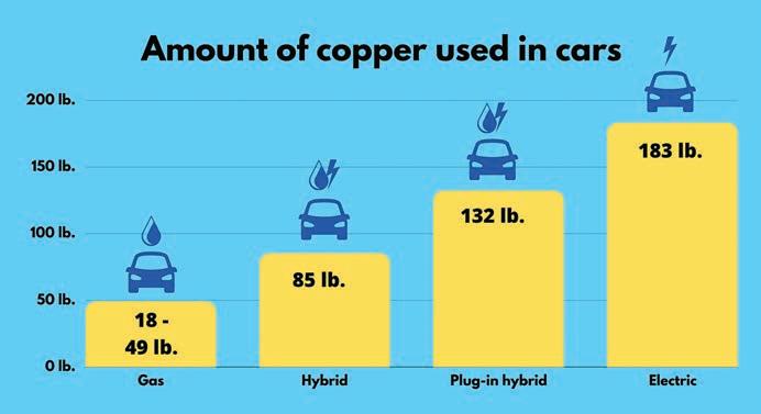
Copper supply/demand: electric vehicles require much more copper than gas-fueled cars.
SUPPLY CHAIN – INTANGIBLES
The shortage of workers, regardless of industry, makes all the other problems seem small by comparison. Grounded aircraft, short of pilots, will increase delivery delays and exacerbate shortages—a major news headline on December 16th, 2021 cited United Airlines in the U.S. was grounding 100 of its jets because of a pilot shortage.
And once our industry does manage to recover, there’s still bad news related to the cost of goods. Government policies targeting massive infrastructure improvements and other social engineering projects will drive the cost of steel and copper through the proverbial roof.
For example, electric cars (much favoured by policymakers) require almost four-times as much copper than a standard internal combustion engine vehicle (see graph above). Steel prices, averaging just under $500 per ton in
July, are projected to hit $1,900 per ton next year. HVAC equipment prices have only one way to go.
LIMP MODE
Wholesalers continue to receive shipments of HVAC parts and pieces, and some are publishing photos on social media of well stocked warehouses hoping to assure customers that needed items are available.
I went to Gary McCreadie’s HVAC Know It All website where I asked Gary, along with several of his technician subscribers, how the supply chain disruption manifests itself in the field. Gary told me he’s “seeing long wait times for various things, but it’s equipment that seems to be scarce.” Apparently certain rooftop units won’t be available until sometime in 2022.
Other technician comments (edited): • “I just saw a quote from (brand x) for a 12.5-ton rooftop with a lead time of 15 weeks…I’m trying to combine parts from two dead ice machines onsite to try and get one working at least.” • “ODU from June, original ETA for parts was October/November. Now it’s April.” • “… suppliers have been taking parts off new units in the warehouse to give to technicians…some condenser fan motors taking 6-12 months to get them in…getting parts for 8-in. PVC and larger has been extremely difficult…” • “Ordered a 3-ton back in August, just came in today (December21st).” • “… we’re having a hard time with HX for sure…package units hard to get.” • “… we can’t get the (brand x) heat banks 10-15kw until 2023 possibly… can’t find 2-in. brass male adapters anywhere on the planet…PEX fittings are hard to come by…certain PVC fittings have a lead time…” • “Heat pumps! Lead time right now, four months.”
Obviously, our magnificently robust supply chain is suffering from a pandemic-related weak link syndrome. Even though some wholesalers have significantly embellished their inventories, it’s the odd missing item here and there holding up the entire enterprise; replenishing some scarce items will be met by new shortages of others.
Our industry is in limp mode for now. Decades of beneficial experience in dealing with scarcities along with bouts of inflation, government regulation, foreign competition and perpetual staffing issues will have to serve us well in the coming year of spot shortages confounded by rising prices. From where I sit today (and I don’t pretend to be a sage), I’m thinking we’re in a situation akin to Winston Churchill’s famous quote after the Battle of Britain victory: “This is not the end. It is not even the beginning of the end. But it is, perhaps, the end of the beginning.”
Certainly, we are not in dire straits as the Brits were then, it simply means our industry will have to rely on our “beneficial experiences” or lessons learned from the past in dealing with shortages of everything. I’m not optimistic, at least in the short run.
Thus, as I’ve mentioned, it’s going to be lessons learned from the past along with contemporaneous “outside the box” thinking that will have to carry our industry through this seemingly unrelenting crisis. <>

The almighty chip: HVAC equipment might have only one microprocessor on board or many more, especially the higher-end products where communicating controls, gas heat modulation, inverter compressor drives, variable speed motors, and electronic refrigerant metering are involved.
Ian McTeer, a regular contributor to HPAC, is an HVAC consultant with over 35 years of experience in the industry. He was most recently a field rep for Trane Canada DSO. McTeer is a refrigeration mechanic and Class 1 Gas technician. For more information Ian can be reached at: imcteer@outlook.com.
THE MAGIC OF REFRIGERANT
What many of our customers (civilians) don’t know, and what many of us professionals take for granted, are the unique characteristics of refrigerant. BY GERRY WAGNER
It is believed that man … early man, discovered fire around two million years ago. Now, I’m old, but I’m not that old, so I have to take the scientists’ word for it.
I suspect within a short time after discovering fire, using it for the purpose of creating heat became one of its earliest practical uses.
Water, being abundant and readily available, then became the obvious media for heat transfer — heat the water with fire and then move the water, or the steam it produced upon boiling, to areas that required heat. Hydronic heating systems can be traced back to the end of the 14th century, and steam heat is documented as early as 1784.
So, it’s not surprising that most of us, when we think of central heating systems, picture fire and water as the key elements.
Now, with the advent of air-to-air heat pump systems, many of us struggle to understand how a system that does not utilize fire or water, can extract heat from outdoor air temperatures as low -30C (-22F).
Well, the answer is magic! …not buying it, right?
Well, it’s magical in my opinion.
What many of our customers (civilians) don’t know, and what many of us professionals take for granted, is the unique characteristics of refrigerant. Along with some really cool compressor technology, it is refrigerant that makes extracting heat from seemingly crazy cold outdoor air possible.
I need to come clean with you about the motivation for the subject matter of this article: I was asked to participate in a project sponsored by the Heating, Refrigeration and Air Conditioning Institute of Canada (HRAI). The project involves creating a document that explains the different types of heating technologies in terms that the typical civilian would understand.
The project was birthed out of the new strict energy conserving and decarbonization codes recently enacted in Vancouver. My portion of the project is to create a civilian-friendly explanation of the air-to-air heat pump. So, as my deadline for this article approached, I thought maybe I could kill two birds with one stone (it’s an old man expression, no birds were harmed in the writing of this article).
OK, lets get back to the task at hand …
What many civilians don’t know is that air conditioners do not add cooling, but rather they extract heat from a room. In this scenario, the evaporator (the coil in the room being conditioned) is passing room air over it (via a fan) and the refrigerant flowing inside the coil is absorbing heat from the room air and sending it to the outside unit (condenser) where the heat is extracted (again, via a fan) and dissipated into the outdoor atmosphere.
So, lets get to the magic part …
R410A refrigerant boils at -48.5C (-55.3F) and it is this that allows it to absorb heat even at -30C (-22F) outdoor air temperature. … is it starting to make sense now?
The transfer media (refrigerant) being used in an air-to-air heat pump is where the magic takes place.
Air-to-air heat pumps when in the “heating” mode reverse the refrigerant flow cycle described earlier, now the outdoor unit coil becomes the evaporator and the indoor unit coil becomes the condenser, releasing the heat extracted from the outdoor air into the room.
It’s also important to know that the refrigerant changes state (liquid to liquid/vapour to gas) as it circulates throughout the system. Mrs. Gillacuddy explained to us in sixth grade science class that matter can change state, but what she didn’t tell us is that when it does, it produces energy in that process — energy that an air-to-air heat pump translates into heat.
The advent of the inverter compressor, the “pump” in the air-to-air heat pump, has taken heat pump technology to yet another level.
The inverter compressor is best described as a modulating compressor, much like the engine in your car. Civilians aren’t expected to understand how a compressor works, but they do generally have a good understanding how an automobile works. Mrs. Gillacuddy knows when she puts the pedal to the metal of her four-door 1967 Chevy Malibu the Malibu takes off. She also knows when she takes her foot off the gas the Malibu slows down, and lastly, she knows when she puts the Malibu in “cruise-control” that the car maintains a pre-set speed.
I tell you this because that is exactly how an inverter compressor works!
When the load is great (it’s hot inside) the compressor will run up to 3,600 RPM like every other compressor in the world, the difference being, when the load is less than great we can take our foot off the gas and as a result, use less gas—use less voltage—but you know what I mean, and when the temperature of the room meets Mrs. Gillacuddy’s setpoint temperature, her comfort number (20C / 70F) well, then the compressor goes into cruise-control, simply using just enough energy to maintain her setpoint.
Ok, we are getting close to the end here, but I do have to tell you about the latest advancement to the inverter compressor which adds yet another level of energy conservation and low outdoor temperature heating ability to the air-to-air heat pump.
The good people at the company I represent have created what they call the “two stage enhanced vapour injection compressor.”
Now, before I go any further, those of you who know me and have attended one of my product training events know that I am brutally honest—I tell you when I like something, and I also tell you when I feel something can be improved. In this case, I’m going to tell you that calling your compressor “vapour injection” is like saying your beer is “fired-brewed.”
Of course you beer is fired brewed, that’s what brewing is. The Stroh Brewery Company clearly had a clever marketing person who took something that every brewery did and made it sound special and unique.
The similarity here is that ALL compressors are vapour injection. We don’t compress liquid, do we?
What is special and unique about the this two-stage enhanced vapour injection compressor is the “two stage” portion of its description.
Adding a second “injection” point for refrigerant in a vapour state but at two different pressures allows for even greater production of energy (in this context, heat) because not only is energy produced when matter changes state, but it is produced when that matter changes pressure.
Well, those of you in the trade are probably thinking to yourself right now, “Yeah, I knew all that already.”
How I hope this article may help you is in relating what you already know to your customer, or potential customer, when trying to sell the attributes of the air-to-air heat pump.
Technology has come a long way over two million years, and although much of it may seem obvious to the professional, it’s not a bad idea to take a moment and appreciate the “magic” that is found in our trade. <>

Illustration of a two-stage vapour injection compressor.


RETHINK YOUR UPFIT. RECHARGE YOUR BUSINESS.

TOUGH JOBS CALL FOR TRUSTED PARTNERS.
At Adrian Steel, we do more than just create high-quality products. We look at the big picture, taking into account all of your business needs and the way you work in and out of the van. Then, we provide you with custom solutions that make your job easier and give you the biggest ROI possible.
To learn more and locate your nearest distributor, go to adriansteel.com/distributors
Gerry Wagner is the vice president of business development for Bathica in Quebec. He has 41 years in the HVAC/R industry working in manufacturing, contracting and training. Contact: GerryWagner@ Bathica.com or TOSOTamerica.com

MH4 HEAT PUMPS Which is Better?
Control options when combining DHW, space heating and cooling using an air-to-water heat pump. By John Siegenthaler
MH10 PROJECT Optimizing Operations
A Montreal west-end health network undertakes an $18.8 million energy efficiency program. By Doug Picklyk
MH14 SNOW MELT Close That Door
Understanding and controlling the inefficiencies of snow melting. By Curtis Bennett

MH18 PRODUCT SHOWCASE
MH20 DESIGN Pel-Air Systems
Considering design options for adding a pellet boiler to a forced-air heating system. By John Siegenthaler
EDITOR
ASSOCIATE EDITOR
ASSOCIATE PUBLISHER
ACCOUNT COORDINATOR
MEDIA DESIGNER
CIRCULATION MANAGER
PUBLISHER
COO
MODERN HYDRONICS
a supplement of Heating Plumbing Air Conditioning Magazine
111 Gordon Baker Road, Suite 400, Toronto, ON M2H 3R1 TEL: 416.442.5600 FAX: 416.510.5140 www.hpacmag.com
Doug Picklyk (416) 510-5218 DPicklyk@hpacmag.com
Logan Caswell (416) 728-6209 LCaswell@hpacmag.com
David Skene (416) 510-6884 DSkene@hpacmag.com
Kim Rossiter (416) 510-6794 KRossiter@hpacmag.com
Emily Sun esun@annexbusinessmedia.com
Urszula Grzyb (416) 442-5600, ext. 3537 ugrzyb@annexbusinessmedia.com
Peter Leonard (416) 510-6847 PLeonard@hpacmag.com
Scott Jamieson
HPAC Magazine receives unsolicited materials (including letters to the editor, press releases, promotional items and images) from time to time. HPAC Magazine, its affiliates and assignees may use, reproduce, publish, re-publish, distribute, store and archive such unsolicited submissions in whole or in part in any form or medium whatsoever, without compensation of any sort. NOTICE: HPAC Magazine, Annex Business Media, their staff, officers, directors and shareholders (hence known as the “Publisher”) assume no liability, obligations, or responsibility for claims arising from advertised products. The Publisher also reserves the right to limit liability for editorial errors, omissions and oversights to a printed correction in a subsequent issue. HPAC Magazine’s editorial is written for management level mechanical industry personnel who have documented training in the mechanical fields in which they work. Manufacturers’ printed instructions, datasheets and notices always take precedence to published editorial statements. Contents Copyright © 2022 by Annex Publishing & Printing Inc. may not be reprinted without permission.
We acknowledge the financial support of the Government of Canada through the Canada Periodical Fund (CPF) for our publishing activities. Proud member of:
WHICH IS BETTER?
Considering control options when combining domestic hot water plus space heating using an air-to-water heat pump.
BY JOHN SIEGENTHALER
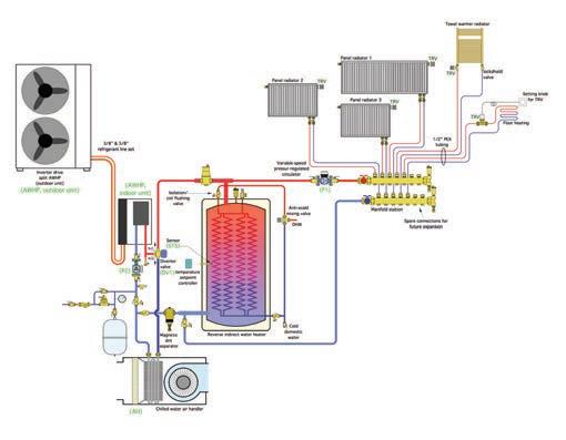
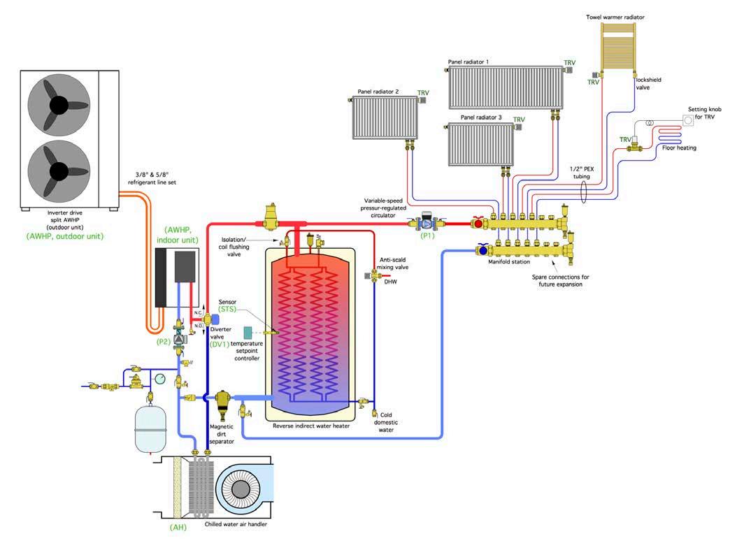
One of the advantages of air-towater heat pumps is their ability to provide space heating, cooling, and domestic water heating. The system shown belown in Figure 1 is a “template” for such a system. When operating in heating mode the heat pump maintains the water in the buffer tank at an elevated temperature suitable for space heating and at least a portion of the domestic hot water (DHW) heating load. The reverse indirect tank provides buffering between the heat pump’s heat output rate and the variable space heating load created by five independently controlled zones of heat emitters. Domestic water absorbs heat as it passes through the copper or stainless-steel coils suspended within the buffer tank.
TRADEOFFS
The combination of space heating and DHW sets up a bit of a “quandary.” To optimize the heat pump’s coefficient of performance (COP) the water in the buffer tank should only be heated to the minimum temperature necessary to maintain comfort in the building. That’s easily accomplished using a properly set up, and relatively inexpensive, outdoor reset controller. Some modern airto-water (ATW) heat pumps even have this control logic included within their internal controls.
However, to optimize the use of heat pump energy for DHW the tank temperature should be maintained at a temperature of at least 120F (49C) at all times. This is based on a nominal five-degree temperature loss across the heat exchanger coils and assumes that DHW delivered from the tank at 115F (46C) is acceptable.
Continued on MH6
Lower tank temperatures will reduce the percentage of heat supplied to domestic water from the heat pump, and thus increase the amount of heat the needed from a supplemental heat source.
Here’s the “quandary”: Is it better to use outdoor reset to control the tank water temperature and take the “penalty” in the form of increased supplemental heating for domestic water heating, or should the heat pump maintain the tank temperature high enough to meet the DHW load 24/7, and take the “hit” of a lower seasonal COP?
COMPLEX SOLUTION
That’s a complex question to answer. It involves specifics for the DHW load relative to space heating load, the COP and heating capacity performance of the heat pump, and the regional climate the system operates in. It also involves the relative cost of installing a dual function buffer tank versus a single function buffer, and the cost of installing a means of providing supplemental heat for boosting DHW to a desired delivery temperature.
THE MODEL
To get a quantitative assessment of these factors I set up a spreadsheet simulation that melds much of this information together. It produced results that seem reasonable given the relatively simple modeling methods used. I’ll share those results with you shortly. First let’s put the “givens” out there along with the “assumptions.”
The spreadsheet simulation is based on a specific heat pump, in this case a nominal 5-ton (@60,000 Btu/h) unit with “low ambient” refrigeration system enabling it to operate at outdoor air temperatures as low as -22F (-30C). The heating capacity and COP of this heat pump, like any ATW heat pump, are highly dependent on operating conditions, specifically outdoor air temperature and the water temperature leaving the heat pump’s condenser. That dependency was modeled using data provided by the manufacturer to create “curve fit” equations that were implemented in the spreadsheet.
The building modeled was a single-family home with a design heat loss of 36,000 Btu/h based on 70F (21C) inside and -10F (-23C) outside temperatures. This home’s hydronic distribution system serves a combination of panel radiators and radiant floor circuits. The heat emitters were sized for a design load using 110F (43C) supply water temperature.
The system’s assumed location was Syracuse, NY (about a 3-hour drive east of Niagara Falls). The simulation used long term “bin” temperature data, as shown in Figure 2.
Bin temperature data organizes the hourly average outdoor temperature, at a given location, into groups that, in this case, are five-degrees Fahrenheit “wide.” For example, Figure 2 shows that the long-term average outdoor temperature in Syracuse is between 5F and 10F for 79 hours per year. Bin temperature tabulations are available from multiple sources including ASHRAE and ACCA Manual J. The bin temperature data drives the space heating load model as well as the performance model for the heat pump heating capacity and COP.
SPACE HEATING ONLY
I modeled several scenarios involving different average buffer tank temperatures. I wanted to see how these temperatures affected the seasonal average COP of the heat pump. The results (next page, Fig. 3) show that the
Figure 2. Long term “bin” seasonal average COP of this temperature data for northern New York state. particular heat pump, as expected, will vary depending on the water temperature of the space heating distribution system. Low temperature systems definitely have the advantage.
For example, a radiant panel system that could supply the building’s design heat load using water at an average temperature of 90F (32C), and without outdoor reset, would allow the heat pump to attain a seasonal average COP of about 3.3. The seasonal COP would decrease to about 2.3 if the system required a sustained average supply temperature of 120F (49C). That’s a significant difference.
In Syracuse (6720 ºF•days “degree days”), where electricity currently costs $0.117/kWh, the savings associated with the higher seasonal average COP would be $213 per year.
Since the heat pump’s performance improves at lower water temperatures it makes sense to keep this temperature as low as possible. That’s easily done using an outdoor reset controller to regulate the buffer tank temperature. I modeled this strategy and found the heat pump’s seasonal COP increased to 3.47. That, in my opinion, is excellent performance for an ATW heat pump in a cold climate application. It rivals the seasonal performance attainable by geothermal water-towater heat pumps in the same application, and at a fraction of the (unsubsidized) installation cost.
BUT WHAT ABOUT DHW?
I also integrated a daily domestic hot water load of 60 gallons
per day heated from 50 to 120F into the spreadsheet, and ran it for several assumed buffer tank temperatures. Any supplemental energy for DHW was assumed to be provided by electric resistance heating (an electric tankless or a tank-type heater). The seasonal average COP was based on the total energy used for space heating plus DHW. The results are shown in Figure 4.
There’s a significant drop in the system’s seasonal average COP as the water temperature maintained in the buffer tank decreases as more electric energy is required to bring DHW up to a consistent temperature of 120F.
The use of full outdoor reset control of tank temperature, along with electric supplemental DHW heating, and assuming that the heat pump provides all domestic water heating during the months with no space heating (May through September), yielded an estimated annual COP of 2.82.
ANOTHER POSSIBILITY
How about operating the heat pump using outdoor reset of the tank temperature, and handling the DHW load with a separate electric resistance heater?
I modeled this scenario and found that the effective seasonal COP of the system (e.g., total energy output of the system divided by total electrical energy input) was 2.57. This reflects that 11% of the total load (space heating + DHW) would now be provided by electric resistance heating at a COP of 1.0.
In the interest of full disclosure here’s what wasn’t included in the computer simulations this article is based on: standby buffer tank heat loss; energy used for heat pump defrost; and energy to operate the system circulator.
Assuming a well-insulated tank, and intelligent defrost controls, I estimate these effects combined would lower the seasonal COP by 5 to 10%.
The higher end of this derating would be for climates with higher relative humidity in winter, and more hours where outside temperatures are in the range of freezing, where the highest amounts of defrosting are necessary.

Figure 3. How buffer tank temperatures affect the average COP of the heat pump. Figure 4. How the seasonal average COP is affected when the heat pump is used for space heating and DHW.
TAKE AWAYS
From an overall performance standpoint, the combination of outdoor reset to regulate buffer tank, along with supplemental electric resistance heating to “top off” DHW, had a projected seasonal system COP of 2.85. This exceeds the estimated COP of 2.57 based on full reset for space heating and shifting all DHW load to electric resistance heating.
For this project, in this location, the annual savings associated with the higher seasonal COP would be about $119/year. That saving has to be weighed against the cost of detailing the system to provide DHW versus using a separate electric water heater.
FINAL THOUGHTS
The heat pump that was modeled does not have a desuperheater, an option available on several water-to-water heat pumps used in geothermal applications. It allows the hot refrigerant gas leaving the heat pump’s compressor to cool from a superheated vapour to a saturated vapour before entering the condenser. That heat is transferred to a stream of domestic water circulating between the heat pump and a tank type water heater. Desuperheaters are possible with split system ATW heat pumps that house the compressor indoors.
An ATW heat pump equipped with a desuperheater could provide much of the energy required for DHW without the need of heat exchanger coils in the buffer tank. That energy is essentially “free” when the heat pump operates in cooling mode (since the heat would otherwise be dissipated outside).
The availability of such a unit would likely swing the design toward a single function buffer tank with the temperature regulated by outdoor reset. A separate heater would be used to provide any small temperature boost needed for consistent DHW delivery.
Another possibility would be controls that operate the heat pump based on outdoor reset control of buffer tank temperature during the heating season, but also allow the heat pump to elevate the buffer tank temperature to 120-130F during the “non-heating” season.
Stay tuned for more unique ways to configure ATW heat pumps systems in future articles.<>

John Siegenthaler, P.E., has more than 40 years of experience in designing modern hydronic heating systems. His latest book is Heating with Renewable Energy (www.hydronicpros.com).

At the Jewish General Hospital in Montreal, 26 air-to-water heat pumps were installed on a custom platform on one of the buildings.

OPTIMIZING OPERATIONS
Montreal west-end health network undertakes $18.8 million energy efficiency retrofit program.
BY DOUG PICKLYK
The Integrated Health and Social Services University Network for West-Central Montreal (locally known as CIUSSS – Centre intégré univeritaire de santé et de services sociaux). The area covered by the CIUSSS is home to approximately 371,500 people who are served by more than 30 member facilities. Included are one of Canada's leading hospitals (the Jewish General Hospital) and an interlocking array of three specialized hospitals, five local community service centres, two rehab centers, six long-term care sites, two day centres and several affiliated research facilities.
In August, 2019, the CIUSSS began working with Énergère, a Quebec-based energy efficiency consultancy and contractor, on a massive energy-savings project involving nine buildings which included changes to boiler rooms and entire mechanical systems to reduce the network’s environmental footprint and increase operational efficiency.
Over the past two-and-a-half years, more than 40 measures were implemented in the nine facilities, including the Jewish General Hospital (JGH), a 637 bed acute-care and teaching hospital that serves as the hub of the CIUSSS West-Central network.
The other buildings optimized include: Mount Sinai Hospital, Richardson Hospital, Catherine Booth Hospital, Henri Bradet Residential Centre, Donald Berman Maimonides Geriatric Centre, Saint Margaret Residential Centre, Saint Andrew Residential Centre, Father Dowd Residential Centre and Miriam Home and Services.
“At some of these facilities we’re removing big boilers that are running at 20% efficiency and replacing them with modern boilers running at 85% or more, and by combining all of these modifications into one project we can recover a lot of energy savings in total,” explains Georges Bendavid, Director of Technical Services for CIUSSS West-Central.
The CIUSSS invested close to $18.8 million for this initiative, of which $6.7 million came from a combination of grants offered through the Government of Quebec and utilities including HydroQuébec and Énergir.
“The strategies that were put into place will allow us to save close to $1.4 million a year in energy costs,” says Bendavid. And based on having to finance about $10 million of the project, the CUISSS is projecting roughly a seven-year payback.
While the project did include lighting upgrades throughout the nine buildings, the heavy lifting for this initiative involved mechanical system upgrades in buildings dating as far back as the 1920s.
NEW BOILERS
All but one of the nine facilities are heated with hydronics (Miriam, a small 25-bed long-term care site, is heated
with electric resistance). In three sites steam boilers were replaced with efficient hot water systems and/or heat pumps for space heating (a steam operation was retained at the JGH for sterilization, humidification and the kitchens).
Where the steam was replaced, they’re running hot water through the same radiators for the perimeter heating, but now they’re able to modulate the water temperature based on outdoor conditions to better control the environment in each room, says Emilia Fernandes, P.Eng., project manager on the CIUSSS technical services team.
AIR HANDLING
In addition to the perimeter heating, all of the steam coils in the air handlers were replaced with hot water. They were re-sized, are being fed with lower temperatures and also have outdoor reset.
In the JGH alone, 24 coils were swapped out from the 100% fresh air systems and systems with return and modulating fresh air. Six of those coils— those in the fresh air systems—use small glycol loops with heat exchangers. “We optimized the amount of fresh air, and made a lot of the systems variable volume to save energy there as well,” says Fernandes. “We’re saving energy in the distribution system where before we were losing a lot of efficiency.”
HEAT PUMPS
The project did not move facilities away from natural gas, but the addition of heat pumps was designed to optimize the energy efficiency in three buildings. “We optimized the boiler systems we had, and at the same time we added the heat pumps to help with the generation of the hot water,” explains Fernandes.
Commercial air-to-water (ATW) heat pumps were installed at three sites: three units at Mount Sinai, two at Maimonides and 26 at the JGH, which also installed a six-section water-to-water Multistack heat pump chiller.
At the JGH, the 26 ATW heat pumps were installed on the roof of one building, and they were placed on a platform that serves as an outside plenum where exhaust from the building goes through the heat pump array tempering the air so the units can run with efficiency even during a Montreal winter.
Two buffer tanks (750 gallons each) were installed in the JGH as part of the loop from the ATW heat pumps to create mass for more stable temperature control and efficient hot water production.
The JGH still operates gas boilers and has water-to-steam heat exchangers, but
Continued on MH12

the system was optimized with the addition of the heat pumps which bring the system up to a certain water temperature, and then the water-to-water heat pumps/chillers boost the temperature.
“We still have a primary high temperature loop and a secondary low temperature loop,” explains Fernandes. “We use the higher temperature to inject into the low temperature.”
The whole distribution system was also re-piped to optimize efficiency and energy savings for the domestic hot water.
Cooling at the JGH is handled with existing chillers—a system optimized in a previous project. However they do have a circuit to unload the new Multistack chiller into its chilled water system.
CONTROL AUTOMATION
“With this type of project, one of the things that is definitely very important is the controls,” says Bendavid. “The capacity to be able to look at what you are doing in real-time and over a period of time, and to also be able to see the energy savings.”
If a facility had an existing control system they tried to keep operations as they were, otherwise they centralized with Delta controls that allows communications to a central room in JGH where operations can be monitored remotely.
The project included a complete review of the control sequences and optimization of the equipment operations to maximize energy savings, including a complete review of the schedules of operation and adjustment of setpoints for the temperature of air and water, the quantity of fresh air supply and exhaust.
“This was done for all major heating, cooling, ventilation and domestic hot water production equipment,” notes Fernandes. “Not only were the sequences optimized, but other control points were added to better control and monitor the systems.”
In addition, a complete recommissioning was done which allowed all the facilities to discover and fix elements that were neglected over the years, and to better coordinate with the building automation systems.
The CIUSSS expects to reduce GHG emissions by 49% annually—with 2,200 tonnes of GHG savings from the ATW heat pumps alone. The annual energy consumption will also be reduced by 39.3 million kilowatt hours, the energy consumed by about 1,637 households.
According to Bendavid, at the end of the day, “This type of project is not looking at just saving energy, it’s really looking at one way to finance the modernization of our aging institutions.” <>
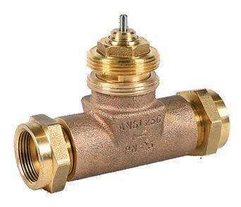

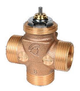
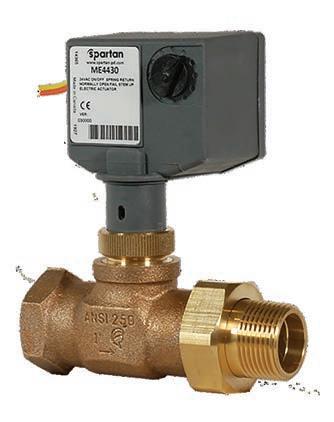
• Lifetime Warranty On Valve Bodies • Canadian Made • Actuators For Any Application • Retrofit Solutions • Simple ‘In-Situ’ Maintenance
Find out more at Spartan-Pd.com
CLOSE THAT DOOR
When it comes to controlling snow melt systems, the goal is to optimize the inherent inefficiencies to the best of your abilities.
BY CURTIS BENNETT
Ican still hear my parents yelling at me in the winter: “Close the door, we are not trying to heat the whole world.” And I’m sure many of you have heard something similar at some point in your lives.
I spent my childhood in rural Alberta where we would have “No School Days” because it was so cold outside that the propane in the school bus would start to gel. So leaving the door to the house open in those temperatures would cool the the place down pretty fast, and it could take some time to heat it back up. Now, as an adult myself, I totally get it, I’m not paying to heat the outside. But wait …
Snow melting is a very big part of our hydronics industry in Canada. I’m not going to sit here and tell you that snow melt systems are all roses and butterflies, because each person reading this (and I hope there are more of you than just my mom) will start laughing and go on to the next article.
Snow melt systems are the most inefficient systems we in the HVAC industry have at our disposal. Each one of those Btu’s that your boiler just made went straight outside, never to be used to heat your house. Poof, gone.
Now I am no mechanical engineer, but I know as a rule—and this will change from region to region—that it’s about 250 Btu’s per square foot to melt snow on a slab, but in actuality this number is not important. The important thing is that the pipes for said systems are in slabs of concrete THAT ARE OUTSIDE.
I did use upper case for a reason. I have told many people in my circle of friends and family about snow melting. None, as of yet, had ever heard of it. The first thing they say is: “Wow that must cost A LOT of money.” Then the second thing is always: “That would be awesome at my house.”
Now don’t get me wrong, melting snow is a useful thing to do, I am just pointing out the heating aspect of it, that’s all. Now let’s take a look at a few things that can make snow melt systems use fewer Btu’s overall.
Let’s quickly go over the basic parts of the snow melt operation (if I miss something I apologize, this is for simplicity). We have the boiler, piping, pumps and controls. I’m not going to talk about pumps and pipes, although yes, you can gain efficiency there, and yes you “should” be trying for that, but, for now we will talk about the other two.
The boiler and controls will determine your system efficiency more than anything else, all else being considered equal. I am also assuming that everything is installed correctly, which is a whole other topic.
Let’s start with the boiler. We have the necessary technology today, and that’s condensing boilers, to be even more specific modulating condensing boilers, but in the case of a snow melt system the condensing part is the most important aspect.
As we should all know, you get the most efficiency out of the boiler when it is condensing, and in the case of snow melting your return water temperature is usually the temperature of the slab, yes I said usually. So if that is the case the max temperature that you should have coming back is around 50F (10C). You don’t need much more than that to melt snow, realistically you can melt snow at 33F (0.5C), but to hasten the snow melting time I have seen many people try to get the slab up to 40F (4.4C) to 45F (7.2C).
Ok, so all that being said, a condensing boiler is perfect for snow melting applications. It’s going to be your most efficient choice.

Sensors in snow melt systems can detect snow or ice on the pavement and trigger the process.
Next, let’s look at what the control does. A snow melt control has three parts: the CPU that makes all the decisions; the slab sensor, which is usually built into the next part; the snow/ ice sensor—this sensor is what lets the control know that there is snow falling or ice forming on the slab.
SNOW SENSOR
The snow sensor can work in a couple different ways. The first is a continuity style sensor, and the other is an optical style. The continuity style sensor basically senses snow by a change in resistance between some metal fingers on the top of the sensor. As snow falls on the sensor it melts between the fingers and causes a “short” circuit in the fingers. This tells the control there is snow.
The optical sensor works by seeing an amount of snow falling. As the snow hits the top of the sensor it is able to see how much snow is falling. It can see the instant there is snow and the instant the snow stops and every variation in between. There is some efficiency that this sensor can provide, and we will hit that in a moment.
SLAB SENSOR
In a snow melt system the slab sensor is what runs the control. It is a big deal to get this slab temperature reading right. Place the sensor too close to any piping and it will get too hot of a reading and the control could shut off the system prematurely.
Likewise, if the slab sensor is not placed anywhere near any piping it may think the slab is too cold and continue to push heat. Sensor placement is something that really needs to be considered.
CONTROL STRATEGY
The control strategy for a snow melt is pretty simple. The main temperature we are controlling is the slab temperature, but we need to know the outdoor temperature as well, because
Continued on MH16

See us at CMPX Booth #404 Partner With Your Industry Experts.

AQUATECH™ offers innovative Lochinvar® commercial and residential building heating and hot water solutions that empower engineers, specifiers, builders and contractors to use solutions that dependably deliver. A building is about more than just products. It’s about people. Your customers, who live, learn, or work in the facilities must have heating and hot water solutions that perform and give them peace of mind. Turn to one of your best resources for heating and hot water solutions, value and people support. Grow your business with AQUATECH.
Represented By

Aqua-Tech Sales and Marketing Inc.
4390 Paletta Court., Unit M, Burlington, ON L7L 5R2 P: 905.631.5815 • F: 905.637.8655 1585 Broadway Street., Unit 106, Port Coquitlam, BC V3C 2M7 P: 778.285.9596 • F: 778-285.9598 aquatech-canada.com
the snow sensor does not actually see “snow” it sees moisture. We have to know it’s cold enough outside that the “moisture” the sensor is reading is snow and not rain. Making sure the outdoor temperature sensor is placed in a good position to get an accurate reading is a huge deal.
The other temperatures we need are supply and return. We need to know the delta T of the fluid we are putting into the slab so we don’t “Shock” it—which is what happens by putting too much heat to the slab. So when the snow sensor senses some moisture, and the temperature outside is cold enough, and the slab temperature is below the set target, then we start pushing heat to the slab and the snow starts to melt. Not instantly but eventually.
You may already know all this stuff, but it’s important. We need to remember all this information in order to know where we can do better.
FINDING EFFICIENCIES
Since we are literally heating the outside, any improvements we can make to save energy and money should be looked at. But what can we do better?
System idling is the practice of keeping the slab just below melting point until the snow sensor sees snow, reducing the amount of time it takes to raise the temperature of the slab to start melting the snow. If you don’t idle the slab it can take hours for the slab to heat up to start melting the snow. However, the amount of time that it’s not snowing usually far outweighs the time that it is. Idling the slab consumes the most energy and money in a snow melt system.
I am not saying that it should not be done, but can we be more efficient? Idling even a couple degrees lower can save a huge amount of energy. Also, we now have the power of the internet at our fingertips and inside some controls. With internet connectivity we can use weather forecasts to do some predicting. Use the forecast to set the control into idle when we think snow is coming instead of idling all the time. We can also see if it is actually snowing in your area and use that along with the snow sensor to ramp up the slab temperature to melt. I won’t get too much into this, just know that it’s coming.
Another big energy hog is the amount of time we use to melt the snow after the snow has stopped. This time is usually called the melt time of the slab and is different for every system. It depends on slab thickness, slab size and the heat capacity of the boiler—things I’m not going to get into. Just know that they’re all different when designed, so being aware of these specifications helps you know your melt time.
If your melt time is too long, then you are wasting valuable energy and money, too little and you still have snow on the slab. Keeping these times to the proper amount can save a lot.
The last item to help save energy is the time at which we know there is snow, and the time we know the snow has stopped. Accurately knowing this can save 15 to 20 minutes at the start of the melt cycle and at the end. It may seem insignificant for one cycle, but add up 20 minutes for 50 cycles a year for 20 years. Couple that with a 2 million Btu/h boiler. I think you see where I am heading. It’s a lot of energy and money that can be saved.
This can be done with proper snow melt sensor placement. Too many times I have seen the sensor placed where the snow drifts at the side of the driveway. Take a look at the surrounding buildings and even vegetation to get a good idea of how the snow may fall in areas of the slab to be melted. Thinking of these things will give the most accurate reading for the snow melt control to use.
This also goes to my point above with the type of snowmelt sensor. The more information the snow sensor can give the control the better the control can make decisions.
Wow, I did not think I had this much to share about snow melting. Hopefully you will take a couple tips out of this article. Just remember, close the damn door, and keep those Btu’s inside. <>
Correct positioning the sensors in the concrete will help system efficiency.
Curtis Bennett C.E.T is product development manager with HBX Control Systems in Calgary. He formed the company with Tom Hermann in 2002. Its control systems are designed, engineered and manufactured in Canada to accommodate a range of hydronic heating and cooling needs in residential, commercial and industrial design applications.


Navien has introduced three new products to its PeakFlow line of scale prevention solutions installed at the cold water supply line before the water heater/combi-boiler to prevent scale build-up within a water heater system. The new models include: PeakFlow S (standard) for a flow rate up to 6 GPM; PeakFlow A (advanced) up to 10 GPM; and PeakFlow C (commercial) for flow rates up to 20 GPM. navieninc.com

RBI Torus condensing stainless steel watertube boilers and water heaters for commercial installations now feature 10:1 turndown using pressure-driven air/fuel mixing. The Torus units are available in sizes ranging from 1,250 to 4,000 MBtu/h with efficiencies of up to 97.5% on boilers and 98% on water heaters. An exclusive telescoping burner door system slides out offering full access to the combustion chamber for an-
nual inspection and service. rbiwaterheaters.com The Viega Radiant Auto-Balancing System (RABS) provides the ability to independently control each zone in a radiant heating system. Balancing valves are not required and installers can commission as many as eight thermostats and 12 circuits per control unit. RABS analyzes the supply water temperature, each circuit’s return temperature and zone air temperatures where a wireless thermostat is used to monitor the system. A web-based app-enabled control lets users manage the system remotely. viega.us

VenTum hydronic air handlers from Thermo 2000 are for residential or light commercial applications and can be paired with a boiler or water heater, and also a heat pump or air conditioning system for cooling. Available in two sizes, VenTum can be installed vertically or horizontally. It includes a high-efficiency ECM fan motor, four-row coil suited for low temperature water, a threespeed circulator pump and a digital controller. thermo2000.com The new Weil-McLain ProTools App, available for iOS and Android, allows contractors and other heating professionals access to information on Weil-McLain boiler setup, maintenance and troubleshooting. The new app’s features include: Troubleshoot (review of fault codes), Find Parts, Review Technical Manuals, Get Tech Support (via phone, email, chat or video call), Retrieve Warranties (register a product or review a warranty), and How-To Videos. weil-mclain.com


The Sanicondens Best Flat from Saniflo is a lower-profile version of its Sanicondens Best condensate pump, with nearly double the tank volume and capable of serving multiple mechanical systems, up to a total of 500,000 Btu/h. The unit combines a condensate pump with pH-neutralizing pellet tray into a single solution. The unit pumps effluent upward to 15 ft. and/or 150 ft. horizontally (with gravity fall). saniflo.ca

PEAK-PERFORMANCE HEATING SYSTEMS
TurboMax
The instantaneous indirect water heater with unmatched exchange capacity, exceptional hot water quality and a lifespan of more than 30 years.
ComboMax ULTRA
An electric boiler and instantaneous water heater: a combination without compromise. VoltMax Increased temperature control. Increased power control. The ideal electric boiler for your commercial projects.
BuffMax
Optimize any type of hydronic system with the BuffMax buffer tank.
DoubleMax
Equipped with an innovative double-wall copper heat exchanger that offers a thermal conductivity that is 17 times greater than that of stainless steel, it reduces the risk of cross contamination.
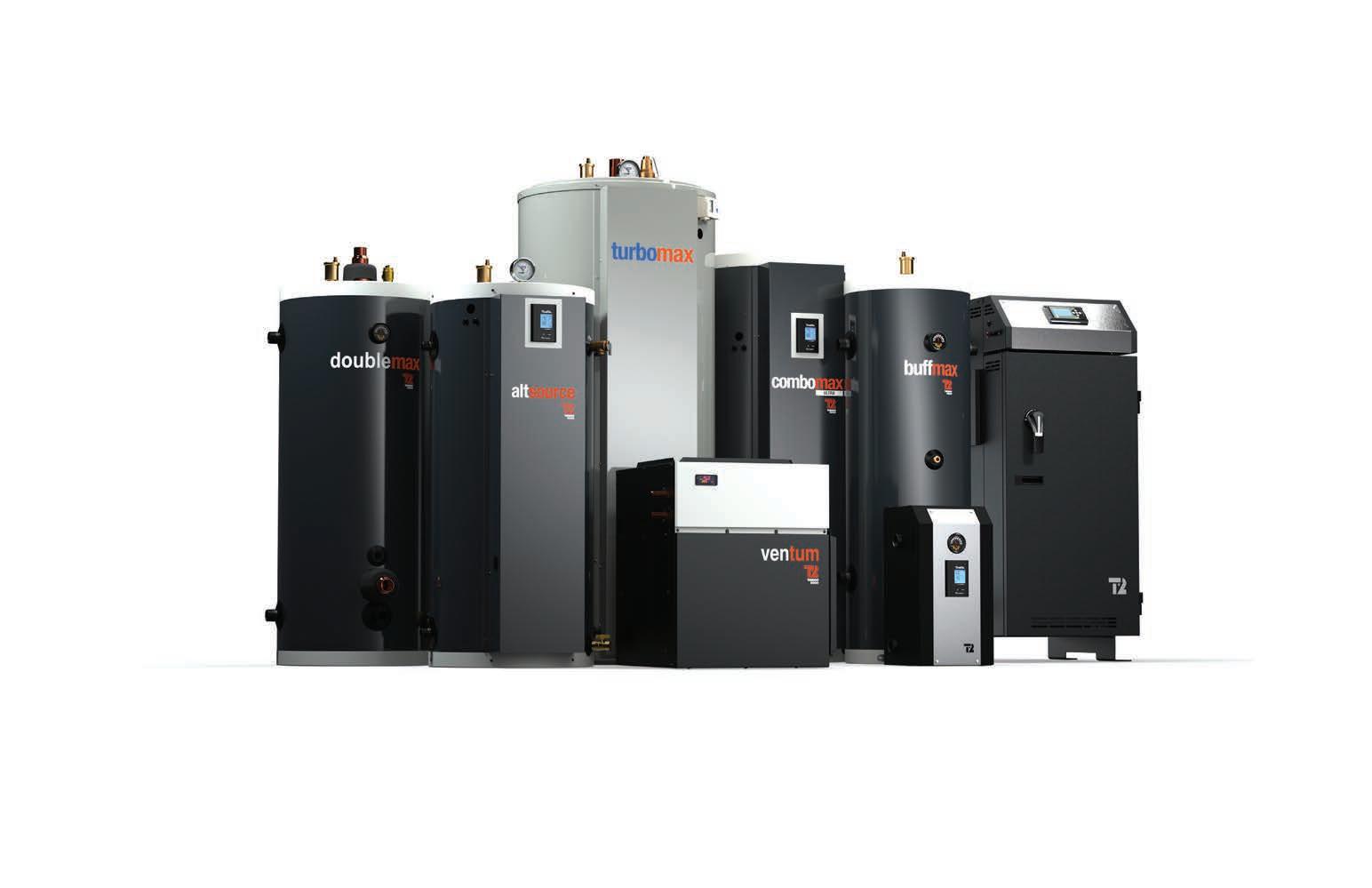
AltSource
The only high-volume electric boiler on the market and the perfect complement to renewable energy.
Ventum
VenTum hydronic air handler conditions the air in a new or existing centralized system with great precision, in any season.
Bth ULTRA and MINI
The reliable and ef cient electric boiler available in compact sizes for your residential needs.
PEL-AIR SYSTEMS
Design options for adding a pellet boiler to a forced-air heating system.
BY JOHN SIEGENTHALER
I’ve described pellet-fueled boiler applications in several past issues of HPAC, and all of them have been situations where the boiler supplied a hydronic distribution system.
While such applications are certainly the prevailing way pellet boilers are used, they are not the only option. It’s possible to couple a pellet boiler to a forced air distribution system.
Most of these applications will be retrofits—perhaps a way to transition a central forced air system away from fossil fuel and onto renewable wood pellets. The economics of such a conversion are increasingly attractive as fossil fuel prices soar.
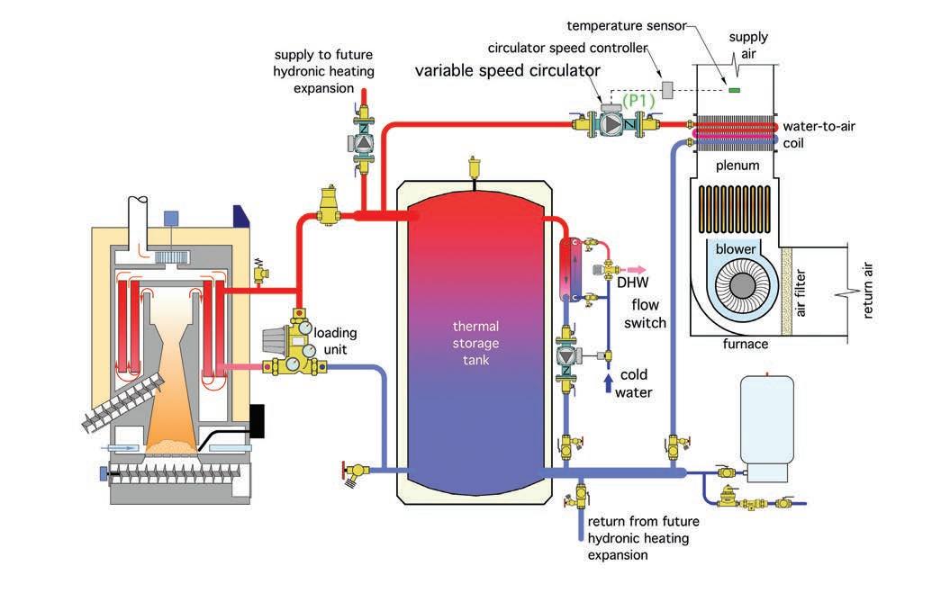
Figure 1 (right) shows a basic system layout. The details between the boiler and thermal storage tank are typical. In this case a “loading unit,” which combines a thermostatic mixing valve and circulator provides flow between the boiler and thermal storage tank. It also prevents sustained flue gas condensation within the boiler by elevating the boiler inlet water temperature above 130F (54.4C) whenever possible.
The thermal storage tank is piped in a “three-pipe” configuration. This allows hot water from the boiler to flow directly to the load if the pellet boiler is operating at the same time as the load.
It also ensures that the thermal mass of the storage tank is fully “engaged” in the energy transfer process. This is critically important for any hydronic system with a biomass heat source.
The heat emitter is a coil mounted in the discharge plenum of a furnace. An

Figure 1. A basic system layout with a pellet boiler feeding a forced air distribution system.


Photo 1. A radiant heated coil.

Figure 3. Connect a magnehelic gauge to measure the pressure drop after the coil is installed.
example of such a radiant coil is shown in Photo 1 (above, top).
Most installations will require sheet metal transitions to be fabricated to join the coil to the furnace plenum as well as to the downstream ducting.
Never mount the coil on the air inlet to a furnace. Doing so could heat the blower motor above its maximum rated operating temperature causing it to lockout or burnout. It’s also likely that such a situation would void the furnace’s warranty due to the potential for high entering air temperatures.
For the system in Figure 1, water flow through the coil is regulated by a variable speed circulator. A closed control loop is established by monitoring the air temperature downstream of the coil.
If this temperature begins to drop below a preset value, such as 110F (43C), the circulator increases speed, which increases heat output from the coil, and vice versa.
There are circulators on the market that have self-contained logic for setpoint temperature control. The temperature sensor in the discharge duct can be wired directly to such a circulator.
Circulators without this functionality, but equipped with either an analog input, (4-20 ma, or 0-10 VDC), or a digital input, (BACnet, LONworks, or PWM), can be regulated by one of several currently available temperature controllers.
Controlling the discharge air temperature is important in this type of application. That’s because the temperature of the water supplied to the coil from the thermal storage tank could be as high as 190F (88C), and perhaps as low as five degrees above the desired leaving air temperature. Without flow regulation there would be times when scorching hot air is pushed through the supply ducting and into the conditioned space. The low density of this air would immediately cause it to rise toward the ceiling, and thus set up excessive air temperature stratification. Overheated air would also cause rapid thermostat cycles, and guaranteed comfort complaints.
Another way to control the discharge air temperature is using a three-way mixing valve. The piping for this is shown in Figure 2 (left).

Figure 4. Install a separate air handler in parallel if both heating and cooling are required.
Figure 5. This diagram shows domestic water heating using brazed plate heat exchanger as well as supply and return piping for another independently controlled hydronics heating zone.
AIR-SIDE DESIGN
Another important consideration is the drop in static pressure as air flows through the plenum coil. Most furnaces have ratings for air flow rate versus the external static pressure of the distribution system they connect to.
In most systems the static pressure is created solely by the duct system. However, when a coil is added to the plenum it will definitely increase the total static pressure the furnace’s blower operates against.
In applications where there’s an existing furnace it’s possible to measure the current static pressure drop by connecting a magnehelic gauge connected as shown in Figure 3 (previous page).
Coil manufacturers can supply data that lists the static pressure drop across their coils as a function of the air flow rate through the coil. Use this data to determine the added static pressure at the nominal air flow rate the system needs to provide.
If the existing forced-air distribution system already has a cooling coil installed, it’s very unlikely there will be sufficient static pressure capacity to accommodate a hot water coil. In this case it’s better to install a separate air handler in parallel with the furnace as shown in Figure 4 (previous page).
Motorized dampers should be installed as shown. They open only when their associated air handler is operating. When closed they prevent air flow from “short circuiting” through the inactive air handler (or furnace).
FUTURE EXPANSIONS
A unique benefit of this approach is that it allows heat from the pellet boiler to be used for ancillary loads—domestic water heating is one example. Adding a manifold station and using it to supply some panel radiators, towel warmers, or radiant panel circuits is another.
The system in Figure 5 (above) shows an “on demand” subassembly for heating domestic water using a stainlesssteel brazed plate heat exchanger, small circulator, and a domestic water flow switch. It also shows supply and return piping for another independently controlled heating zone. There are many possible variations. The key concept is the ability to expand the system for the future needs of the building without extensive modifications.
I’ll close by admitting that I prefer hydronic heating distribution systems whenever possible. But I’m also a realist. There are a lot of forced air systems out there that could potentially undergo a pellet boiler “make-over”. Doing so not only transitions the system to a renewable fuel, it also opens up a wide range of possibilities to suit the future needs of the building. <>
John Siegenthaler, P.E., has more than 40 years of experience in designing modern hydronic heating systems. His latest book is Heating with Renewable Energy (visit: www.hydronicpros.com).


