
5 minute read
FINALIS


Caleffi’s innovative thermal solution for the control of safe and sanitary domestic hot water combines three main components: LEGIOMIX® digital mixing valve that delivers accurately mixed water temperature and integrates calendar-based thermal disinfection; ThermoSetter™ field adjustable thermal balancing valves that feature a bypass option for disinfection; and SinkMixer™ 4-port anti-scald valves for reliable point-ofuse safety. Approvals include compliance with U.S. and Canadian plumbing codes. CALEFFI GUARANTEED.
In either case, the electric water heater provides a backup source of domestic hot water if the heat pump were down for service.
Chilled To Perfection
Cooling is provided by routing chilled water from the heat pump, through the diverter valve, to the coil of an air handler.
The variable speed compressor in the heat pump automatically adjusts to maintain a set chilled water delivery temperature - typically in the range of 45 to 55F (7 to 12C).
The chilled water flows through the coil of an air handler equipped with a condensate drip pan. Cooled and dehumidified air is delivered to the entire building through a ducting system.
The original system shown in Figure 1 cannot simultaneously heat the buffer tank and send chilled fluid to the air handler. One of these loads must take priority over the other.
If maintaining the temperature of the buffer tank is the priority, so as to maximize preheating of domestic water, the system controls would be configured to temporarily stop chilled fluid production and flow to the air handler coil while the temperature of the buffer tank is boosted, which typically only takes 5 to 10 minutes.
If cooling is the priority, heat input to the buffer tank needs to be temporarily interrupted when the house thermostat calls for cooling. If the cooling call is sustained, the electric water heater can take over the DHW load until the cooling load is satisfied.
Dual Purpose Ducting
Since there’s going to be a ducting system for cooling, why not use it for ventilation?
Doing so would certainly reduce cost compared to installing another air distribution system solely for ventilation.
In fact, why not enhance the system by using the coil in the air handler for “boosting” the temperature of incoming ventilation air during cold winter operation, and thus eliminate possible cool air delivery to the house?
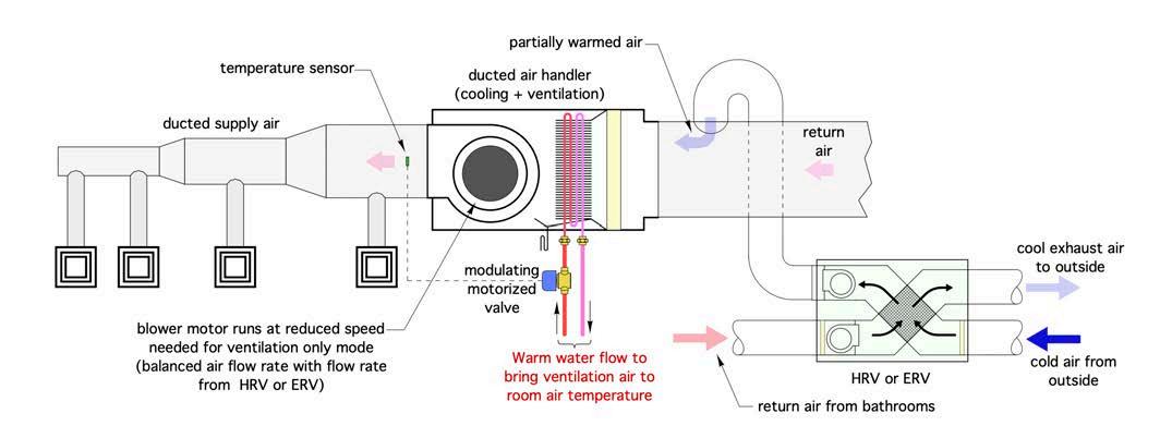
Figure 2 (above) shows one approach for connecting the HRV (or ERV) to the return trunk duct of the air handler, along with hydronic trim to provide that boost function.
The smaller ducts on the “house side” of the HRV connect to the return trunk leading into the air handler. The “stale” air is pulled from one or more bathrooms. The fresh outdoor air, after absorbing heat from the exhaust stream, is injected into the return air side of the air handler.
This configuration can operate in three different modes:
1. Ventilation-only mode
2. Cooling plus ventilation mode
3. Ventilation plus boost mode
For ventilation-only mode the blower in the air handler should provide an air flow rate just above that of the HRV. This ensures that all the incoming fresh air will be entrained in the air flow that’s headed for the diffusers in the house. It also reduces input power to the blower motor in the air handler. Most air handlers have blower motors with multiple speed tap wiring. Check with the air handler manufacturer regarding the best option to bring the air flow rate down to perhaps 100 to 150 cubic feet per minute (CFM). Some air handlers may not be able to reduce their blower speed to such a low value. That’s okay from the standpoint of distributing fresh air. It just means higher electrical power consumption by the blower.
During cooling mode the blower speed would be set to provide 350 to 400 CFM of air flow per ton of cooling capacity. Thus, for an air handler delivering 3 tons (36,000 Btu/h) of cooling, the air flow rate would be about 1050 to 1200 CFM. Again, this will require the system to use the appropriate speed tap on the blower motor.
The ventilation plus boost mode is intended for times when outdoor temperaContinued on MH12
Navien NCB-H combi-boilers


Unmatched heating and DHW performance, all in one compact unit
• Heating up to 150,000 BTU/h and DHW up to 210,000 BTU/h
• Up to 80% smaller than floor standing boiler and tank water heater
• Optimized DHW priority with mixing valve and water adjustment valve to provide consistent DHW temperatures and industry leading flow rates
• Dual stainless steel heat exchangers for heating and separate SS heat exchanger for DHW
• Built-in controls for 3 zone pumps or 3 zone valves
• Heating TDR up to 11:1 and DHW TDR is 15:1 tures are cold. The intent is not to heat the house with the ventilation air, it’s to introduce air into living spaces at about the same temperature as those spaces.
To learn more about the best-selling combi-boilers in North America, visit navieninc.com.

For example, assume the outside temperature is -10F (-23C), and the HRV is recovering about 70% of the heat from the exhaust air stream that leaves the occupied space at 70F (21C).
This would make the fresh air temperature delivered from the HRV about 46F (8C). That’s going to feel pretty cool to occupants if it’s not carefully mixed with room air before reaching occupied areas.
If the boost function is used, this air could be introduced in occupied spaces at a neutral temperature and far less concern about creating uncomfortable conditions when it’s frigid outside.
Under these conditions it’s possible to pass heated fluid through the air handler’s coil to boost the temperature of the ventilation air prior to introducing it to occupied space. A modulating two-way valve is used to regulate the flow of warm fluid through the coil. The flow rate is controlled based on maintaining a set supply air temperature on the outlet side of the air handler.

A word of caution is in order. If the system is located where outdoor temperatures are well below freezing much of the winter, the coil in the air handler needs to be protected against freezing. That’s “automatic” with the monobloc air-to-water heat pump system shown in Figure 1 because the entire system operates with a 30% solution of propylene glycol.
If the system operated with water some type of failsafe control would be needed to automatically turn off the HRV if the coil in the air handler approaches a potential freezing condition.
Figure 3 shows the same system as Figure 1, but with the piping needed to supply water to the air handler coil.
The coil is supplied through a threeway diverting valve. When this valve is off, the coil is connected to the piping path for cooling. When the valve is energized the coil is connected to the warm water circuit.
The pressure differential to drive the latter is supplied by the continuously operating distribution circulator. The modulating two-way valve regulates the flow rate through the coil based on maintaining a set air delivery temperature. This valve should be selected with an equal percentage characteristic.
Offer It All
The longstanding “stigma” that residential hydronic systems can’t provide cooling is slowly waning as air-to-water and geothermal water-to-water heat pumps gain market share against boilers. This sets the stage for progressive hydronic professionals to offer heating, domestic hot water, and cooling.
Why not extend this even farther to include heat recovery ventilation (HRV)? The market for such total solutions is quickly developing.
Are you prepared to participate and profit? <>
John Siegenthaler, P.E., has over 40 years of experience designing modern hydronic heating systems and is the author of Modern Hydronic Heating (4th edition) and Heating with Renewable Energy (visit hydronicpros.com).


