19 minute read
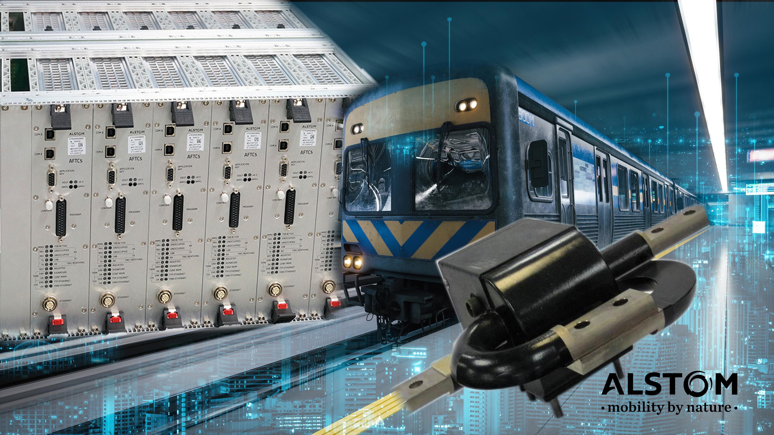
Cover Article - Alstom - Alstom Audio Frequency Track Circuit Technology: Innovation in Urban Transit Train Control


Cover Article - Alstom
Alstom Audio Frequency Track Circuit Technology: Innovation in Urban Transit Train Control
Back to Table of Contents
Authors: Leandro Aveiro, Brandon Gaskin, and Howard Goldberg
We’ve all done it – living or visiting a major metropolitan area and riding their subway or transit system to get from one place to another. We expect it to be safe, on-time and even enjoyable. The primary function of a transit signaling system is to safely move as many people as possible. Accomplishing this lofty goal requires trains to travel as close to each other as possible (called “headway”) while maintaining a safe and smooth ride. To do this, the signaling system must “know” where trains are at all times. The track circuit, or more specifically the Audio Frequency Track Circuit (AFTC), is a subsystem used for this purpose in urban transit applications.
What is a track circuit and why are they needed?
There are many different types of track circuits in use today. A track circuit utilizes the track rails as conductors in an electrical circuit between transmit and receive devices, which define the limits of the track circuit. When the solid, electrically conductive wheels and axles of a train roll into a track circuit or if a rail is cracked or broken, the signal between the transmit and receive devices is interrupted and the system declares
16 | The ROCHESTER ENGINEER NOVEMBER 2022 the presence of a train in that track circuit. Depending on the application, track circuits can employ electrical signals that are simple DC (direct current), pulsed DC, low frequency AC (60Hz, 100Hz), or Audio Frequencies (1KHz to 10KHz).
A key feature of track circuits is their ability to detect rail defects and breaks. Although there are competing technology alternatives to track circuits that use radiobased communication and devices called axle-counters to detect train position, these technologies do not use the rails as a medium for signaling and therefore they cannot detect rail defects like track circuits can. Rails experience punishing stresses from trains, exposure to seasonal temperature extremes, and daily thermal cycling, which all contribute to cracking over time. Detection of rail defects and breaks is key to safely operating trains and is a tangible benefit to transit operators in avoiding derailments. Newer track circuit technologies, like the Alstom AFTC Gen 5 discussed later, are capable of analyzing rail signals and reporting potential rail defects before they become hazardous while preventing trains from entering areas with suspected broken rails.
cover article - Alstom
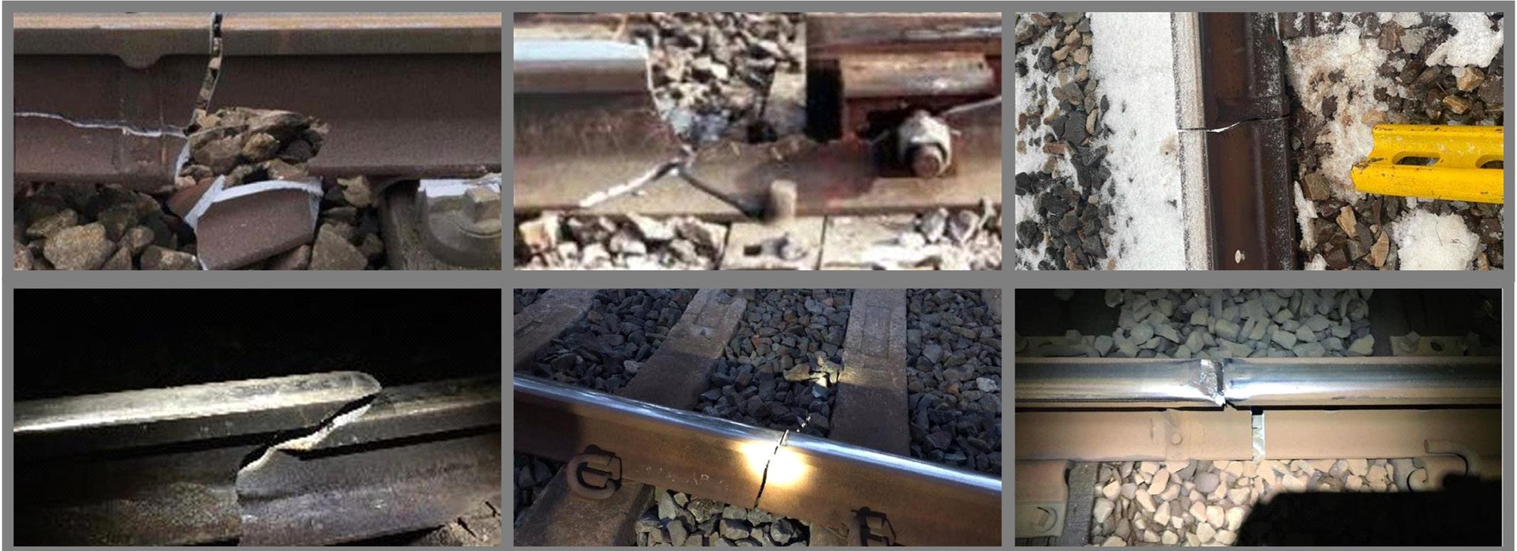
Figure 1. Examples of broken rails detected by Alstom AFTC technology.
Why Audio Frequency Track Circuits for Urban Transit?
Audio frequencies are optimal for urban transit system track circuits where the objective is short headway time, suitable for urban transit operations where trains are up to about 750 feet in length and stations are relatively close together. Although rail has a very low resistance per unit length due to its large cross-sectional area, its impedance at audio frequencies is surprisingly high in comparison. Due to this impedance, audio electrical signals can travel just far enough down the track to make track circuit lengths up to 1200 feet practical, compatible with the aforementioned short headway times and train length. The impedance is a result, in part, of the self-inductance of rail. The geometry of tracks where multiple long, parallel rails are separated by a short distance (such as the standard 56.6 inches between rails), make mutual inductance between rails and tracks significant. Engineering an AFTC system requires careful attention to frequency selection and coupling paths to ensure the system is both safe and reliable.
The tracks and rails themselves are an integral part of the AFTC system. Alstom has developed models to characterize the track itself. It turns out that track behaves much like a classic transmission line and can be modelled with lumped transmission line parameters mathematically computed from empirical data measured in the field on various types of track, ties (including concrete, wood, composite, or steel “beams” that secure the rails to each other), conditions (including dry, wet, and frozen), and ballast material (including stone or concrete which is the “filling” between and under the ties to secure the rail structure) over the audio frequency range.
In comparison to AFTC, DC, 60Hz, and 100Hz signals can travel much farther in rail due to its lower impedance at these lower frequencies, resulting in much longer track circuits. Longer track circuits, up to about a mile, are suitable for applications like commuter transit where stations are much farther apart than in urban transit whereas track circuits can be several miles long for freight trains. With that said, this article focuses on Audio Frequency Track Circuits.
cover article - Alstom
Alstom AFTC Technology Evolution
Alstom in Rochester, NY, formerly General Railway Signal, pioneered the AFTC in the late 1960s and early 1970s in transit systems like WMATA (Washington Metropolitan Area Transit Authority), MBTA (Massachusetts Bay Transportation Authority), CTA (Chicago Transit Authority), and MARTA (Metropolitan Atlanta Rapid Transit Authority) to name a few. The original AFTCs have demonstrated reliability and safety for over 40 years and are being upgraded with Alstom’s newest state-of-the-art generation, named AFTC Gen 5 (AFTC5).
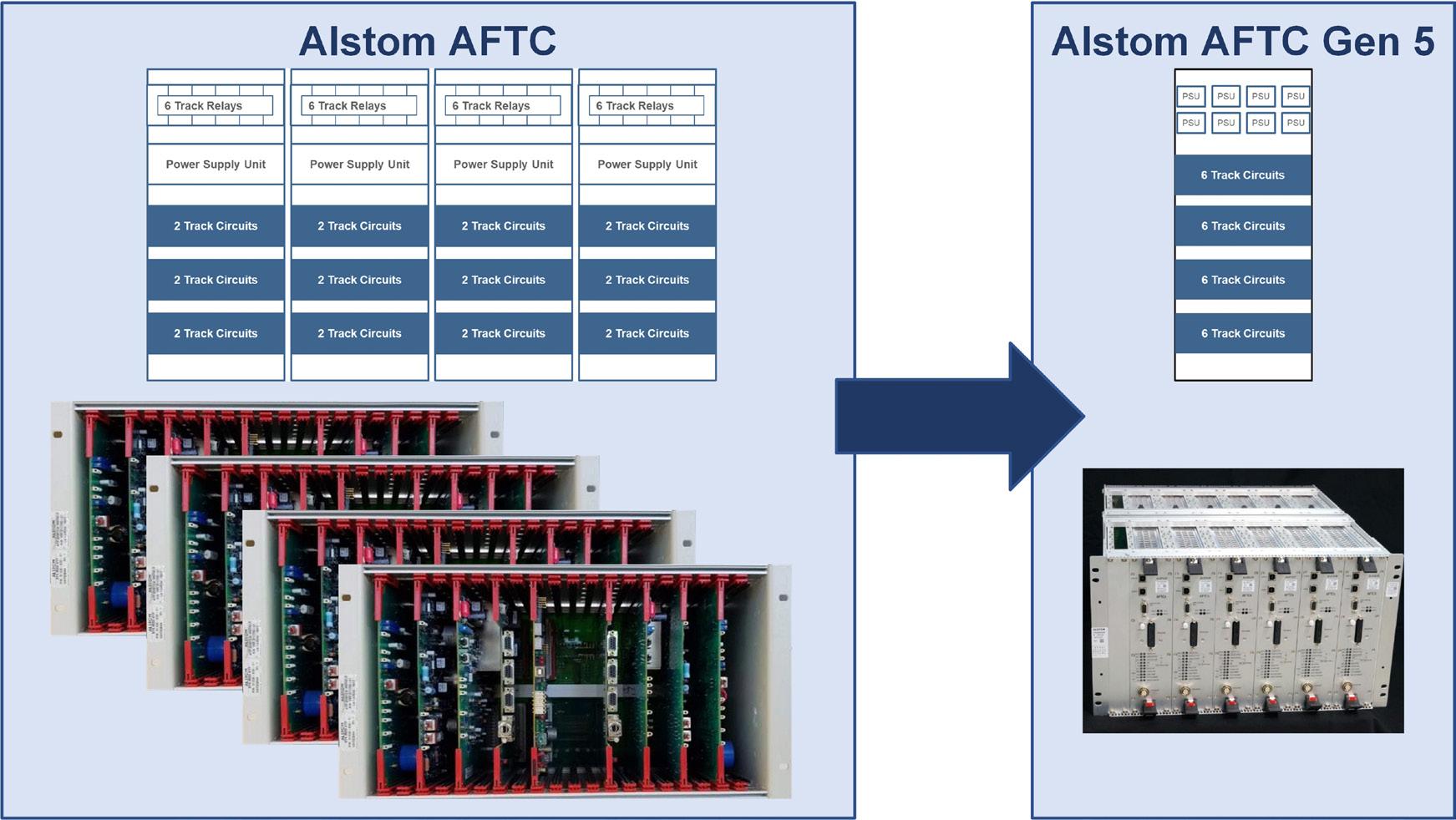
The Alstom AFTC generations prior to AFTC5 have been mostly designed with failsafe analog discrete electrical components requiring installations to employ extensive manual wiring, expensive electromechanical relays and a large amount of physical space. AFTC5 is designed to replace earlier generations, using up to 75% less space thanks to Alstom’s latest networked computer-based safety architecture. Compared to previous generations, AFTC5 provides enhanced flexibility in application configurations, maintenance monitoring, upgradability, diagnostics, and reduced life-cycle costs as would be expected in a modern embedded product.
Continued on page 18
NOVEMBER 2022 The ROCHESTER ENGINEER | 17
Cover Article - Alstom, continued
Back to Table of Contents
Figure 2. Evolution from previous generation Alstom AFTC (left) requiring 4 discretely wired equipment racks each with three twotrack-circuit modules, to Alstom AFTC Gen 5 (right) requiring one networked equipment rack with four 6-trackcircuit modules for the same number of
track circuits but with enhanced functionality.
Part of a Larger Train Control System How does AFTC5 Work?
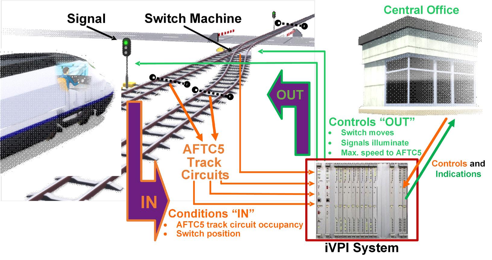
At the system level, once AFTC5 detects a train, it reports the occupancy to another subsystem, generically called an “interlocking controller,” and specifically Alstom’s (integrated Vital Processor Interlocking - iVPI). iVPI is a subsystem also originally developed in Alstom’s Rochester location in the 1980s and has been evolving ever since. iVPI is a failsafe computer that uses inputs from AFTC5, track switches, the central office, and other iVPIs to automatically and safely set outputs such as routes, speeds, and color light signals for trains and their operators. iVPI contains the logic required to read inputs and set outputs for failsafe and efficient train control and works seamlessly with AFTC5. The main components of an AFTC5based track circuit include: (1) the AFTC5 module; (2) a specially tuned transformer called a Wee-Z® Bond; and (3) the rails. The AFTC5 modules are installed in bungalows or train control rooms, located adjacent to the tracks, or in stations
while the Wee-Z® Bonds are installed directly on the railroad ties between the rails. The AFTC5 modules perform the processing, signal generation and amplification, safety algorithm, and user interface functions. AFTC5 modules communicate safety-critical information with iVPI
Figure 3. AFTC5 is a portion of an overall urban train control system which includes iVPI, a control office, and rail control appliances like switches and signals. AFTC5’s main role is to (1) detect track occupancy and report it to iVPI and (2) to generate and transmit the appropriate speed signal to the rails as commanded by iVPI.
18 | The ROCHESTER ENGINEER NOVEMBER 2022 cover article - Alstom
via an Alstom failsafe protocol over Ethernet. The main safety-critical communication parameters include track occupancy state and speed signal to be transmitted. Other nonsafety information such as equipment status use a standard communication protocol.
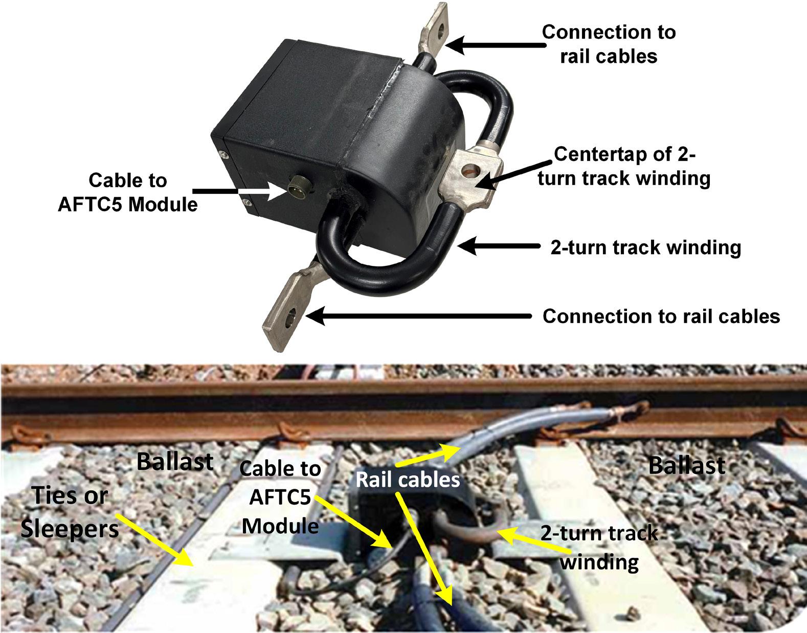
The Wee-Z® Bond uses a specially tuned transformer to pass the modulated audio signals to and from the track. Since electrified urban transit systems use rails to return DC traction current from the rail cars to the substations, Wee-Z® Bonds also function as part of a balanced, low resistance return path for high levels of such DC current. This is why heavy cables are shown in Figure 4, typically 250500MCM (thousand circular mils) each, connecting the Wee-Z® Bond’s two-turn track winding to the rails. The two-turn track winding serves as a low resistance path for DC as well as the means for coupling the audio signal to and from the rails.
AFTC5 has two main functions: (1) to detect track occupancy, including track defects and (2) to inject a speed signal into the rails for the train to receive, representing the maximum allowable speed for each train. To detect track occupancy, AFTC5 transmits a modulated audio carrier frequency into the track rails using a Wee-Z® Bond at one end of the track circuit. Another Wee-Z® Bond at the receive end couples the track
cover article - Alstom
Figure 4. A typical Wee-Z® Bond by itself (top). Installation between the rails (bottom) with heavy rail cables bolted to the Wee-Z® Bond’s 1.25” diameter copper two-turn track winding.
signal back to the AFTC5 electronics. Each Wee-Z® Bond is the transmitter for one track circuit and a receiver for the adjacent track circuit, but is also able to transmit a speed signal simultaneously with the track occupancy signal. For example, in Figure 5 “TRACK CIRCUIT 1” and “TRACK CIRCUIT 2” share one Wee-Z® Bond tuned to f3 and f5 while “TRACK CIRCUIT 2” and “TRACK CIRCUIT 3” share one Wee-Z® Bond tuned to f3 and f7. Using advanced DSP and safety-critical algorithms to analyze both the transmitted and received signal, AFTC5 determines train presence or if a significant rail defect or other anomaly is present.
Track occupancy carrier frequencies and modulation rates of adjacent track circuits are different so that AFTC5 can discern track circuits. Track occupancy carrier frequencies and modulation rates in each system are applied to track circuits such that there is a frequency rotation to maximize the distance between track circuits utilizing the same track occupancy carrier frequency. Further, there is a set of specific audio frequencies and modulation rates engineered for each system, such that they are compatible with the electrical environment of the transit system where DC traction substations and various vehicular propulsion technologies exist and produce potentially interfering audio signals. For example, the DC in the “third rail” used for propulsion is produced from a 60Hz utility feed and rectifiers. Much like the output of a common full-wave bridge rectifier, DC substations place “ripple” on their output voltage, where the ripple frequency is based on the number of rectifier elements used, typically six (creating a six times 60Hz fundamental) or 12 (creating a 12 times 60Hz fundamental). AFTC5 audio carrier frequencies are therefore chosen to avoid harmonics from DC substations which are multiples of the 360Hz or 720Hz fundamental frequencies.
For speed signals, AFTC5 transmits a second modulated carrier frequency into the
Continued on page 20
NOVEMBER 2022 The ROCHESTER ENGINEER | 19
Cover Article - Alstom, continued
Back to Table of Contents
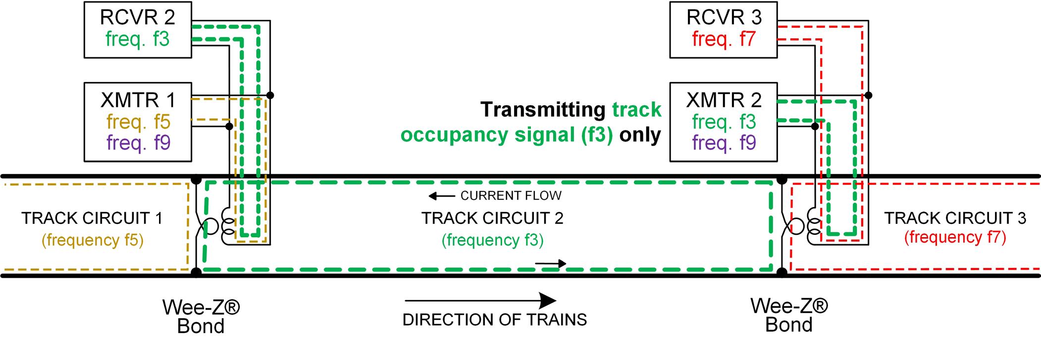
Figure 5. Three consecutive AFTC5 track circuits show a track occupancy carrier frequency rotation – f5, f3, and f7 for track circuits 1, 2 and 3, respectively. There is a 4th audio frequency not shown, f1. The pattern is then repeated down the track: f1, f5, f3, f7, f1, f5, f3, f7, f1….. Modulation rates are assigned to each track occupancy carrier frequency and are not shown here.
rails along with the track occupancy signal using the same Wee-Z® Bonds as track occupancy signals. The speed signal is only transmitted once a given track circuit is occupied and the speed signal is always transmitted to the front of a train using the electrical circuit formed by the transmitting Wee-Z® Bond, rail, and front axle of the train. The train then receives the speed signal current using magnetic pickup coils mounted to the train ahead of the front wheels above the rail. The speed signal carrier frequency is the same in every track circuit; however, the modulation rate sent to the train changes since it represents the maximum train speed. Maximum train speed changes depending on the proximity of other trains and on rail conditions, for example.
AFTC5 and its suite of tools have the unique ability to discern rail defects and maintenance needs based upon recognizing specific characteristics and trends in the signals received from the rails. Depending on the specific conditions, this gives AFTC5 the ability to notify maintenance personnel in advance of rail breaks, detached rail cables, or other issues that can potentially cause derailments or service interruptions.
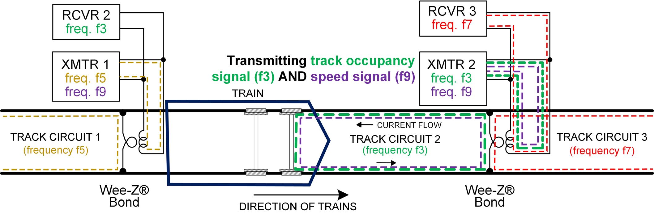
Figure 6. Similar to previous figure, but showing the presence of a train that triggers the speed signal to turn ON from the Wee-Z® Bond ahead of the train in Track Circuit 2. Every track circuit has the ability to provide a speed signal to the train using carrier frequency f9, modulated at a rate representing the safe maximum speed for that track circuit.
20 | The ROCHESTER ENGINEER NOVEMBER 2022 cover article - Alstom
It’s Not as Easy as it Seems
Theoretically, this all may seem straightforward. But in the real world, AFTC5 must be able to operate safety and reliably in the abusive transit system environment where weather, mechanical shock and vibration, rail and ballast conditions, wheel-to-rail interface variations, and EMI (electro-magnetic interference) can all influence the performance and safety of the system. AFTC5 will always assume an occupied safe-state if it does not receive the correct signal but AFTC5 must also be able to tolerate the aforementioned external influences to operate safely and reliably.
AFTC5 is live!
Twelve locations on the Chicago Transit Authority (CTA) Blue Line have upgraded signaling technology in the form of AFTC5 paired with iVPI. The Blue Line leads to the Chicago O’Hare Airport, making it one of the busiest lines for CTA, America’s second largest transportation system.
A thousand miles away, another ongoing project achieved revenue service in six of 27 locations for the MBTA’s (Massachusetts Bay Transportation Authority) Red and Orange Lines, the busiest heavy rail subways in Boston. These lines are being upgraded to AFTC5 and iVPI, as well as Model 5F switch machines and LED signals. q
Biographies:
Leandro V. Aveiro
Leandro has worked for Alstom for 17 years and has exercised multiple roles during this period, from software engineering to management of product development. Currently Leandro is responsible for the Verification and Validation of products developed by Alstom in North America and is a member of the board of directors of the Rochester Engineering Society since June 2022.
Brandon Gaskin
As a project architect and train detection system subject matter expert, Brandon is responsible for the project integration and deployment of Alstom’s new AFTC5 audio frequency track circuit solution. He graduated from Florida Institute of Technology with a bachelor of science in Electrical Engineering.
Howard I. Goldberg, P.E.
Howard has been with Alstom for 27 years and is currently an Engineer-of-Record as an Electrical Engineer and Senior Expert in Railway System Safety for urban transit signaling projects. He also promotes the Engineering Profession and mentors junior engineers at Alstom while actively participating in industry standards organizations such as AREMA (American Railway Engineering and Maintenance-of-Way Association) and APTA (American Public Transportation Association).
NOVEMBER 2022 The ROCHESTER ENGINEER | 21
RIT Student Feature
Back to Table of Contents
Simple, Accurate and Power-Free Detection of Infectious Diseases
by Mengdi Bao, PhD Student
In the past decade, an increasing number of human infectious diseases has been identified. As transportation networks become more accessible, the spread of infectious diseases accelerates, posing significant economic and social challenges. For example, the largest Ebola outbreak in 2014-2016 resulted in over 10,000 deaths and a $32 billion loss of gross domestic product. As of August 2022, the coronavirus 2019 pandemic, caused by severe acute respiratory syndrome coronavirus 2 (SARS-CoV-2), has resulted in over 550 million confirmed cases, and 6 million deaths. To effectively control the spread of pathogens, one common way is to provide diagnosis, followed by isolation of infected patients. This emphasizes the significance of simple, rapid and accurate diagnostic methods for pathogen detection.
Since its discovery in 1983 by the American biochemist Kary Mullis, polymerase chain reaction (PCR) has been the gold standard technology for pathogen detection. It can generate many copies of pathogen DNA from a very small amount. For amplification, the DNA sample is first mixed with special chemicals (primers, nucleotides, mix buffers, and Taq polymerases) in a test tube, and then incubated in a thermal cycler machine. The machine provides specific different temperatures required during the PCR process, including 95 ˚C for DNA strands separation (denaturing), 55 ˚C for primers binding (annealing), and 72 ˚C for new strand synthesis (extension). Today, PCR is renowned for its high accuracy in pathogen detection, but it typically requires well-trained personnel and electrical machines, thus limiting its applicability in settings with limited resources.
Another widely adapted diagnostic tool is developed on the basis of antibody-antigen interactions. The tool is either designed to detect the presence of viral proteins (antigen testing) or to identify the host antibodies produced in response to prior infections (antibody testing). Typically, antigen testing is more commonly used to diagnose because antibodies take 1-2 weeks to develop. In real-world diagnostics, antigen testing is commonly performed on a lateral flow strip as it is low-cost and simple enough for individuals without training. Compared with PCR diagnosis, antigen testing provides results more rapidly, but it yields less accurate results.

Figure 1. Principle of pathogen detection using CRISPR technology
22 | The ROCHESTER ENGINEER NOVEMBER 2022 rit student feature
In recent years, clustered regularly interspaced short palindromic repeats (CRISPR)-associated (Cas) proteins have emerged as a promising technology for pathogen detection. It was initially found in prokaryotic organisms, such as bacteria and archaea, which preserve the partial genome of a previously infected virus and identifies the virus when re-infected. Certain Cas proteins, specially Cas12a and Cas13, can randomly degrade single-stranded DNA (ssDNA) once they have identified the virus. Owing to this unique property, ssDNA probes are designed with a fluorophore and a quencher in a typical CRISPR-based diagnosis. Upon recognition of pathogen DNA, the activated Cas nucleases can degrade a substantial amount of fluorophore-quencher ssDNA, thereby resulting in remarkably high accurate pathogen detection (Figure 1). In comparison to PCR diagnosis, CRISPR-Cas detection does not require a thermal cycler machine, making it an excellent alternative for simple diagnosis. However, the majority of CRISPR detection is performed by manual pipetting, which is laborious, time-consuming and may contaminate to produce false positive results.
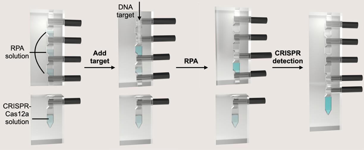
Therefore, our lab (Nanobiosensing, Nanomanufacturing, Nanomaterials Lab) at Rochester Institute of Technology designed a device that integrates the CRISPR for simple, power-free and pipette-free detection of pathogens. The device, depicted in Figure 2, consists of Figure 2. Working principle of the designed device for pathogens detection four reaction chambers that are physically separated from one another by carbon fiber rods. The top three chambers were utilized for target amplification, which increases the quantity of pathogen DNA, thereby enabling CRISPR to detect even trace amounts of pathogen DNA in a sample. The bottom chamber was used for the CRISPR detection. Prior to the reaction, the special chemicals were preloaded into the specific chambers for amplification and detection. During the reaction, the rods were removed, and the device was manually rotated so that the chemicals could thoroughly mix. To facilitate pathogen detection without electrical power, the entire reaction was heated with a disposable hand warmer pouch. Following the CRISPR reaction, the generated signal can be seen with the naked eye when illuminated by an inexpensive flashlight. In contrast to the top three chambers, the bottom chamber has a pyramidal structure with a narrower base, making liquid collection easier. This can lead to more illumination and higher signals. Figure 3. Scheme for the designed device fabrication process Another benefit of our device is its simple and inexpensive fabrication.
Continued on page 24...
rit student feature NOVEMBER 2022 The ROCHESTER ENGINEER | 23
RIT Student Feature, Continued
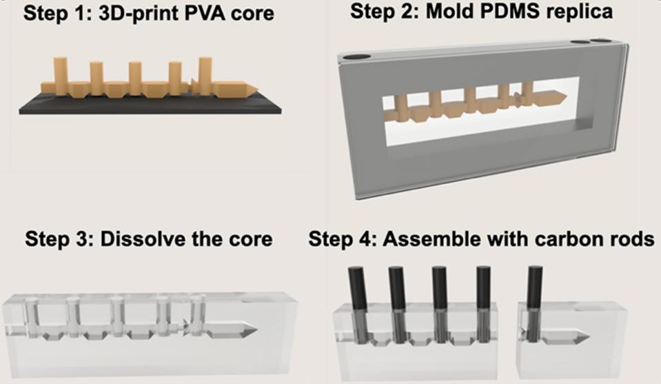
Figure 3 illustrates the fabrication procedure, which consists of four primary steps (printing, molding, dissolving and assembly). Initially, polyvinyl alcohol (PVA), which can be dissolved in water, was used for printing the temporal core. Next, a PDMS replica was made by first placing the core inside a specialized aluminum mold, and then pouring the PDMS mixture into the mold. Following that, the PVA core was dissolved in water, and then the PDMS replica was cut into two separate pieces for amplification and detection, respectively. To control the flow and mixing of pre-loaded reagents, the pull-out carbon fiber rods were assembled into the device as gates. Our team used carbon fiber rods to separate each chamber due to the following benefits: excellent chemical resistance, low weight, low thermal expansion, high stiffness, and no fluorescence when illuminated under a flashlight. The 3D printer used in this study can be purchased for less than $1,000, making it accessible to many different types of experimental groups and new businesses.
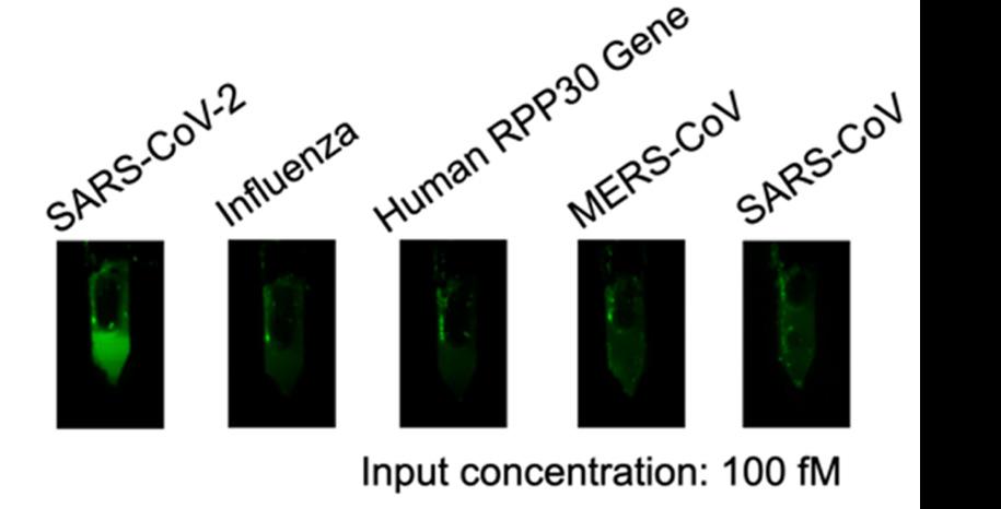
In this work, the performance of the device was tested using partial SARS-CoV-2 genome. When the pathogen DNA was higher than 10 fM (6 x 10³ copies/µL), we noticed a distinct color with a flashlight illumination. The device was also evaluated using pathogen DNA with a similar genome to SARS-CoV-2. Only the sample containing SARSCoV-2 DNA exhibits bright fluorescence Figure 4. Images of the reaction products with the input of SARS-CoV-2, Influenza, MERS-CoV, Human RPP30 gene, and SARS-CoV color, indicating the high specificity of our device (Figure 4). In addition, we employed a machine learning algorithm to improve the reliability and precision of visible readouts. The created algorithm shows an accuracy of ~100% for distinguishing color differences between samples without and without pathogen DNA.
We anticipate that our simple, power-free, pipette-free device will be useful in the future for the diagnosis of infectious diseases in both clinical settings and areas with limited access to healthcare resources.
Our work has been published on Lab on a Chip and selected as HOT Articles in 2022. q
Author Bio:
Mengdi Bao is currently pursuing her Ph.D. degree in the Department of Mechanical Engineering at Rochester Institute of Technology, Rochester, NY. Her previously received her Master in Bioengineering in 2017 and her BS in Biomedical Engineering in 2015. Her research interest includes diagnostic assay development, biosensor design and fabrication, and chemical bioconjugation.
24 | The ROCHESTER ENGINEER NOVEMBER 2022 rit student feature


