HOW DO YOU PERCEIVE INTRADERMAL DELIVERY?
THINK AGAIN...
THROUGH THICK AND THIN: MODELLING THE DELIVERY OF NON-NEWTONIAN FORMULATIONS

HOW DO YOU PERCEIVE INTRADERMAL DELIVERY?
THINK AGAIN...
THROUGH THICK AND THIN: MODELLING THE DELIVERY OF NON-NEWTONIAN FORMULATIONS
TESTING THE ACCURACY OF INFUSION PUMP DOSES


ONdrugDelivery Issue No 160, May 30th, 2024
DELIVERING INJECTABLES: DEVICES & FORMULATIONS
This edition is one in the ONdrugDelivery series of publications. Each issue focuses on a specific topic within the field of drug delivery, and is supported by industry leaders in that field.
EDITORIAL CALENDAR 2024/25
May/Jun
2024 Oral Drug Delivery
Jun Connecting Drug Delivery
Jun/Jul Industrialising Drug Delivery
Sep Wearable Injectors
Sep/Oct Drug Delivery & Environmental Sustainability
Oct Prefilled Syringes & Injection Devices
Nov Pulmonary & Nasal Drug Delivery
Dec Connecting Drug Delivery
Jan 2025 Prefilled Syringes & Injection Devices
Feb Skin Drug Delivery:
Dermal, Transdermal & Microneedles
Mar Ophthalmic Drug Delivery
Apr Pulmonary & Nasal Drug Delivery
Apr/May Drug Delivery & Environmental Sustainability
May Injectable Drug Delivery: Formulations & Devices
EDITORIAL:
Guy Furness, Proprietor & Publisher E: guy.furness@ondrugdelivery.com
CREATIVE DESIGN:
Simon Smith, Creative Director (Freelance) E: simon.smith@ondrugdelivery.com
SUBSCRIPTIONS:
Audrey Furness (subscriptions@ondrugdelivery.com)
Print + Digital subscription: £99/year + postage Digital Only subscription: free.
ADVERTISING: Guy Furness (guy.furness@ondrugdelivery.com)
ONdrugDelivery is published by Frederick Furness Publishing Ltd
The Candlemakers, West Street, Lewes East Sussex, BN7 2NZ, United Kingdom T: +44 1273 47 28 28
Registered in England: Company No 8348388 ISSN 2049-145X print / ISSN 2049-1468 pdf
Copyright © 2024 Frederick Furness Publishing Ltd

ONdrugDelivery Magazine is printed sustainably by Newman Thomson Ltd, West Sussex, UK, using Forest Stewardship Council® certified recycled paper, vegetable-based inks, biodegradable laminates and carbon balanced materials offset via the World Land Trust™ following ISO140001 processes. ONdrugDelivery in print is sustainably shipped to events by DHL using GoGreen Plus whereby carbon insetting of at least 30% is achieved through the use of Sustainable Aviation Fuel (SAF), a biofuel substitute for traditional jet fuel, produced from renewable sources such as vegetable oils, animal fats, waste products, and agricultural crops. The magazine is mailed to individual readers outside the UK by DHL using GoGreen, which offsets 100% of CO2 emissions.
The ONdrugDelivery logo is a registered trademark of Frederick Furness Publishing Ltd.
as a result of any information contained in this publication.
Transitioning from Vial to Subcutaneous Injection Devices for Biological Drug Products
Michael Adler, Director Drug Product Design; Venkata Appa Reddy Goli, Research Fellow, Formulation and Process Development; Andrea Allmendinger, Chief Scientific Officer; and Prof Hanns-Christian Mahler, Chief Enablement Officer
ten23 health
Accelerating Combination Product Development Using Digital Twin Technology
Dan Cowen, Senior Consultant, Applied Sciences; Sebastian White, Principal Engineer, Fluidics & Analytical Mechanics; and Anthony Robinson, Senior Consultant, Mechatronics and Integrated Systems
Cambridge Consultants
Accelerating Innovation: The Power of Parallel Development for an Autoinjector Launch
Jeff Clement, Executive Director, Technical Sales –Development and Manufacturing; and Bill Welch, Executive Director of Services
PCI Pharma Services
How Do You Perceive Intradermal Delivery? Think again…
Nicky Bertollo, Chief Technology Officer and Co-Founder; Adam Rock, Strategic Partnerships and Commercialisation Manager; and Ronan Byrne, Chief Executive Officer and Co-Founder
Pharma Latch
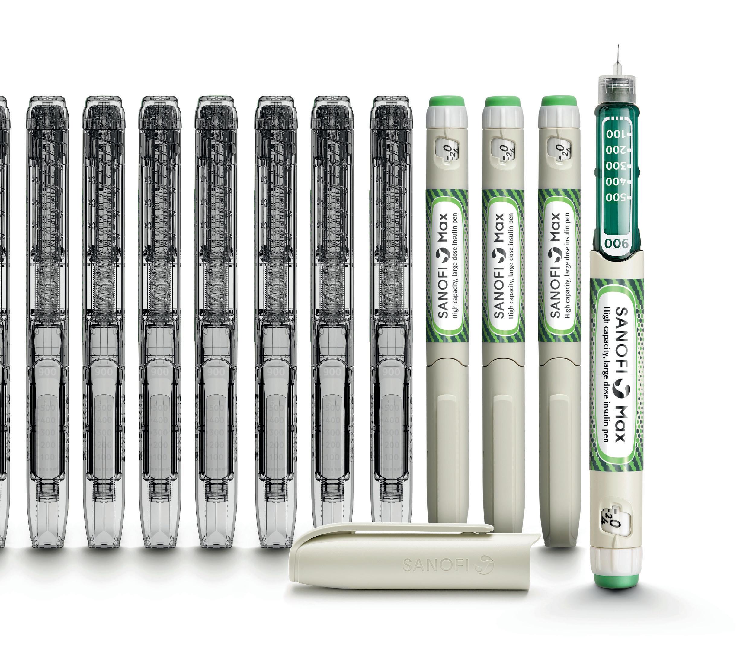
Addressing Diabesity with Pen Injector Platforms
Cécile Gross, Global Category Manager, Parenteral; and Mark Tunkel, Global Category Director, Services
Nemera
Delivering on GLP-1 Demand: a Combination of Device
Offerings and Supply Strategy
Manuela Giacon, Product Manager, Pen Injectors; and Josh Gordon, Product Manager, Auto-Injectors
Stevanato Group
SHL Molly® Autoinjectors: Powering the Next Wave of Cardiometabolic Care
Lars Berger, Senior Manager; and Eric Linvill, Senior CAE Engineer
SHL Medical
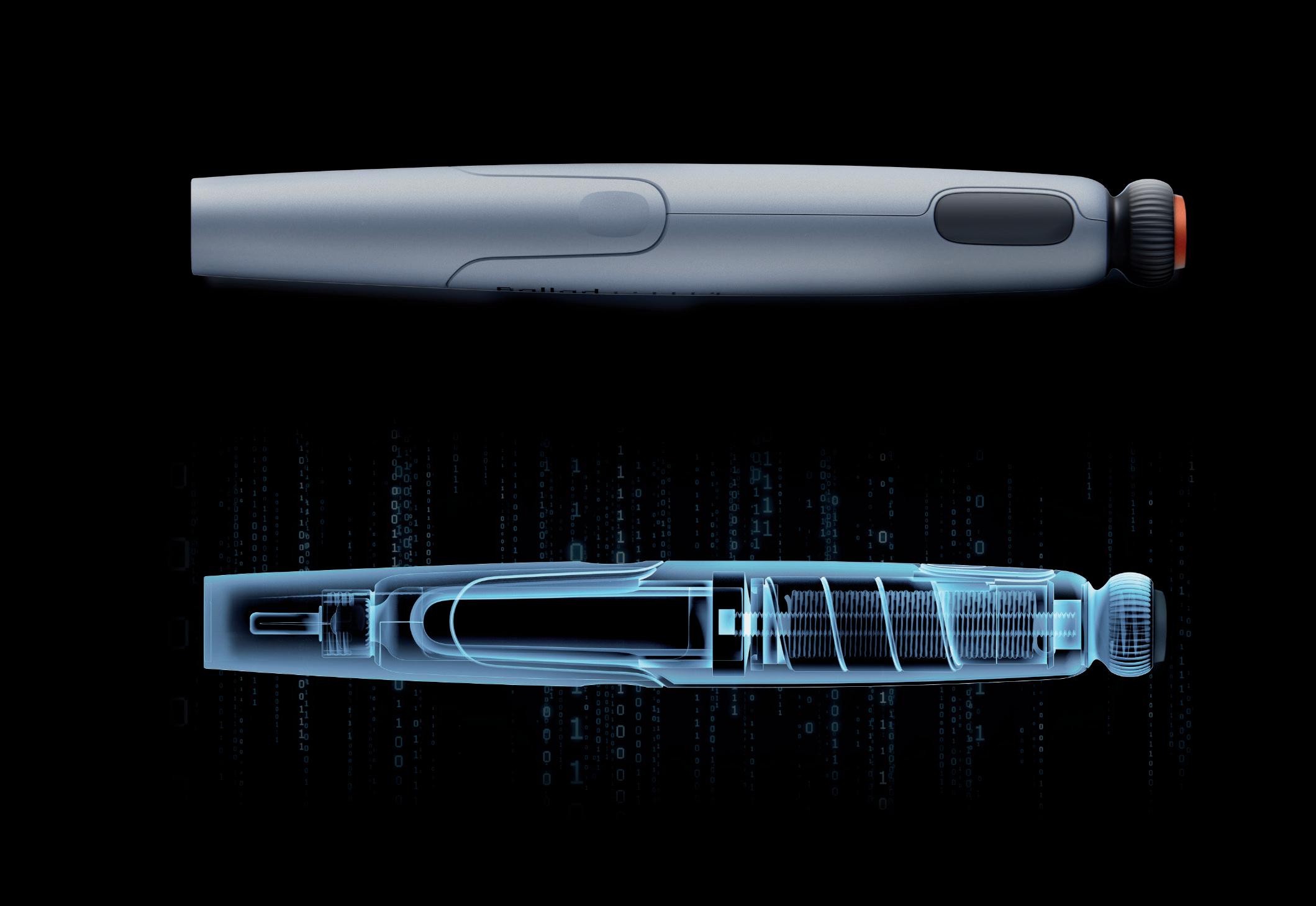
Through Thick and Thin: Modelling the Delivery of Non-Newtonian Formulations
Alex Vasiev, Principal Biomedical Engineer
Springboard
Navigating the Transition from MDD to MDR for Co-Packaged Combination Products
Paul Scannell, Senior Director
West Pharmaceutical Services
Challenges in Testing the Accuracy of Infusion Pump Doses
Lucas Foerster, Product Manager Lab Weighing Applications
Satorius
Dieter Peissig, Active Medical Device Expert
B. Braun
The Challenges of Developing Drug Delivery Devices for the Japanese Market
Olivia Houselander, Business Development Manager
Owen Mumford
OXYCAPT Vial’s Container Closure Integrity at -80°C with Dry Ice and CO2 Barrier
Masashi Miura, Researcher; and Tomohiro Suzuki, Associate General Manager
Mitsubishi Gas Chemical
Vial Stopper Compatibility: Criteria and Testing Methods for Pharmaceutical Packaging
Laure-Hélène Guillemot, Technical Product Manager, Vial Containment Solutions; Benjamin Brocco, Marketing Manager; Edouard Pagnoud, Product Line Manager, Vial Containment Solutions; and Pascal Sircoulomb, Business Development Director, Vial Containment Solutions
Aptar Pharma
Packaging Material Identification to Ensure Selection of Best-Matching Components for Parenteral Drugs
Uwe Rothhaar, Director; Daniel Haines, Head of Pharma Services North America; Matthias Bicker, Scientific Advisor; and Thomas Schmidt, Study Director, Analytical Services
SCHOTT Pharma
Company
Vetter Pharma

Built-in
Clearly
Smart
Production-ready
In this article, Michael Adler, PhD, Director Drug Product Design, Venkata Appa Reddy Goli, Research Fellow, Formulation and Process Development, Andrea Allmendinger, PhD, Chief Scientific Officer, and Hanns-Christian Mahler, Chief Enablement Officer, all at ten23 health, discuss the various factors that need to be considered when transferring to a delivery device for subcutaneous injection, such as a prefilled syringe or autoinjector, during clinical trials or post-launch, especially when transferring from a vial format for intravenous infusion.
The subcutaneous (SC) route is becoming increasingly important for the administration of biologics. With the development of SC injection devices, the paradigm of drug product development has continued to shift towards patient centricity by enabling self-administration and ease of use for patients, improving compliance and adherence and reducing the burden on healthcare systems.1 The number of approved monoclonal antibody (mAb)
products has been increasing over the last few decades, with a proportional increase in the number of SC products (Figure 1), based on the information compiled by ten23 health on US FDA-approved products. About 79 mAb products, excluding antibody-drug conjugates (ADCs), were approved between 2015 and 2023, which is twice the number of products approved between 1994 and 2014 (31 products). 41% of mAb products approved between
Dr Michael Adler
Director Drug Product Design
E: michael.adler@ten23.health
Venkata Appa Reddy Goli
Research Fellow, Formulation and Process Development
E: venkata.goli@ten23.health
Dr Andrea Allmendinger
Chief Scientific Officer
E: andrea.allmendinger@ten23.health
Prof Hanns-Christian Mahler
Chief Enablement Officer
E: hanns-christian.mahler@ten23.health
ten23 health AG
Mattenstrasse 22
4058 Basel
Switzerland
www.ten23.health
“41% of mAb products approved between 2015 and 2023 are administered by SC injection, whereas it was 24% between 1994 and 2014.”
2015 and 2023 are administered by SC injection, whereas it was 24% between 1994 and 2014. In 2023, an impressive number of mAb products (7 out of 12) were approved for SC administration, marking the highest number per year in the past 30 years. Numbers in other countries (e.g. EU approvals) are in line with the trend towards SC administration of biologic injectables.
As innovators change their product lifecycle management approach towards increased patient centricity, transitioning from intravenous (IV) infusion to SC administration with an injection device can be a huge game-changer (patient focus, compliance, differentiation from competitors), with notable examples being Herceptin® (trastuzumab, Roche/ Genentech), MabThera® (rituximab, Roche/ Genentech), Actemra® (tocilizumab, Roche/ Genentech), Benlysta® (belimumab, GSK), Entyvio® (vedolizumab, Takeda) and others. There are also cases where biosimilars have been developed for SC administration when originators were solely available for IV.
Advances in the understanding of SC delivery and SC drug delivery technologies have unlocked the perceived “volume limitation” for SC administration, which have traditionally been assumed to have a maximum 0.5–2 mL injection volume. Much larger injection volumes, even up to 10 mL or more, can now be delivered subcutaneously, with 25 mL being studied in a recently published study in the absence of a permeation enhancer.2
In some cases, co- or subsequent administration of hyaluronidases (enzymes that locally and transiently digest the SC tissue) can facilitate administration of larger injection volumes by reducing SC tissue back pressure.3 Using innovative SC delivery devices, such as on-body injectors (OBIs), including West’s (PA, US) SmartDose or Ypsomed’s (Burgdorf, Switzerland) YpsoDose, can also facilitate larger-
volume SC injections without a permeation enhancing enzyme. Herceptin Hylecta™ (trastuzumab/hyaluronidase, Roche/ Genentech), Rituxan Hycela® (rituximab hyaluronidase, Roche/Genentech), Darzalex Faspro ® (daratumumab/ hyaluronidase, Janssen) and Phesgo® (pertuzumab/trastuzumab/hyaluronidase, Roche/Genentech) are examples of SC administered drugs exceeding 2 mL using hyaluronidase co-formulations. On the other hand, Repatha® (evolocumab, Amgen) used the Pushtronex® system (West’s SmartDose®) and Ultomiris® (ravulizumab, Alexion) used West’s SmartDose® to deliver 3.5 mL of solution.
In first-in-human (FIH) clinical trials, biologics are usually administered by IV injection or infusion for various reasons, such as ensuring 100% bioavailability. Some companies already test SC delivery in FIH studies to establish SC injection early on, which saves time for non-clinical and clinical bridging later. Indeed, establishing and understanding bioavailability early during development can be essential to avoid later undesirable surprises, because bioavailability after SC administration may be low due to SC matrix and tissue interaction, depending on the molecular properties of the drug.
Vial presentations often serve the need for early clinical studies, as the dose volume can be easily adjusted for dose escalation and the development of vial presentations is less complex than for injection devices, making it less prone to technical issues that might lead to a delay of FIH clinical trials. The SC administration across different dose groups in the FIH study out of a vial would be achieved by administering:
1. Different volumes, such as using disposable syringes with or without SC clinical pumps
2. Using a placebo/diluent formulation to dilute to the respectively required concentrations and then administering similar volume, such as by using a disposable syringe with or without SC clinical pumps.
Hence, having a high-concentration formulation for SC administration is highly recommended when choosing a vial presentation for FIH clinical trials. If using a prefilled syringe (PFS) for SC administration in FIH studies, it should preferably contain the highest dose, using either additional
dose strengths (concentrations or volumes) or “down dosing” the syringe to administer lower doses (although this approach is not recommended).
Using vials for SC administration in commercial settings may also be a consideration. However, it is obvious that errors and issues with the usability of such products, such as handling vials and solution withdrawal, may present significant issues, depending on the user group. Therefore, a transition from a vial to an SC injection device is common for biologics and can occur either during clinical development or post-launch. These devices include PFSs, autoinjectors, pen injectors and OBIs.
When switching to an SC injection device, either during or after clinical trials, the following scenarios are possible:
1. IV vial to SC injection device during clinical development
2. IV vial to SC injection device post-launch
3. SC vial to SC injection device during clinical development
4. SC vial to SC injection device postlaunch
5. SC injection device to SC injection device post-launch.
Moving from IV to SC (cases 1 and 2) is more complex as it includes a change of the route of administration (RoA). As the bioavailability after SC injection for biologics is less than 100%, implying a modified pharmacokinetic (PK) profile, the dose must be adapted. Knowledge about the anticipated bioavailability is therefore key. Furthermore, some drugs may have other safety and/or efficacy profiles with SC vs IV administration, depending on their mode of action. In addition, because of the smaller injection volume for SC administration compared with IV infusion, a change of formulation and container closure system (CCS) is usually required, necessitating a change in the manufacturing process.
The transition from an IV infusion or SC vial to an SC injection device requires several chemistry, manufacturing and controls (CMC) development activities, as well as clinical and non-clinical, depending on the timing and scope of the change:
• Formulation development
• Primary packaging selection and integration with formulation
• Device selection and device development
• Drug-device integration
• Drug product manufacturing process development
• Bridging studies
– Comparative stability studies, including real-time and accelerated stress stability and characterisation
– Non-clinical studies
– Clinical studies.
The increasing trend of SC administration has been accompanied by a rise in highconcentration formulations, due to the limited injection volume for SC administration. Since 2015, a notable number of high-concentration (>100 mg/mL) formulations have been approved (44%), with even higher numbers in 2023 (more than 50%). However, the use of largevolume injection products at mid-range concentrations is also on the rise, reducing some of the technical challenges related to high-concentration formulations. Generally, the higher the concentration, the greater the protein aggregation, the higher
the viscosity and the higher the concentration of potential impurities from the drug substance process (e.g. lipases), which may also impact stability. Therefore, the concentration of the API is usually a compromise between injectability, stability, manufacturability and acceptable dose volume to achieve the desired dose (Figure 2).
Biologic formulations commonly contain a buffer system (e.g. histidine, acetate) to ensure adequate pH, a stabiliser/tonicity adjuster (e.g. sucrose, trehalose) and a surfactant (e.g. polysorbate 80, polysorbate 20 or poloxamer 188) to protect the protein against adsorption and interfacial stress. Excipients must be safe in the concentrations and doses to be administered (considering the target indications, for example, adult versus pediatric use) and acceptable for parenteral use from a safety and regulatory standpoint. High-concentration mAb formulations frequently contain excipients such as salts or amino acids to modify or weaken protein-protein interactions, thereby lowering the viscosity while maintaining
colloidal stability. Based on ten23 health’s assessments of marketed products, 26 of 48 (~55%) approved high-concentration injectable mAb products contain amino acids, including arginine, proline, glycine and methionine. Some of the highconcentration formulations also use amino acids or chelators to prevent oxidation of the API or polysorbate.
The optimal formulation pH depends on the stability and viscosity, considering tolerability in the patient population. According to ten23 health’s assessment, most SC products are formulated to between pH 5.2 and 6.2, where most of the products show acceptable stability. Histidine remains the leading buffer of choice (~60%) for high-concentration mAb products, followed by acetate. Over the years, the usage of citrate as a buffer has reduced considerably for SC administration compared with the IV route, based on some (poorly studied, in the authors’ view) concerns on citrate formulation causing injection pain upon SC injection. Some products initially approved with citrate buffer were re-formulated, such as adalimumab and ixekizumab. Such re-formulations may also generate intellectual property.
Injection devices represent the pinnacle of convenience for patients, enhancing comfort, adherence and overall satisfaction. These devices, typically arriving as ready-to-use products, streamline handling, eliminating the need for additional manipulation and reducing errors. Specifically designed for SC administration, they empower self-administration, facilitating the transition to at-home care settings and yielding significant economic savings. The engineering behind these devices prioritises patient needs, informed by human factors studies, to ensure optimal usability.
While traditional PFSs and autoinjectors paved the way, recent advancements include larger-volume OBIs and connected devices that enhance treatment scheduling and outcomes. This diversity in product presentation enables flexible care settings, promoting medical compliance. However, the development of injection devices presents additional technical and regulatory challenges compared with vial presentations, requiring careful consideration of drugdevice integration and manufacturing,
including selection of the primary packaging and device itself. At present, vial presentations remain favoured for early-stage development, offering flexible dosing and fewer technical hurdles, with the transition to devices necessitating further consideration deeper into development. Preferably, such vial to PFS changes would not require any facility or provider tech transfers, which always add additional risk and cost, rather than being manufactured at the same line, facility and vendor, such as ten23 health.
When selecting an SC injection device, several critical factors must be considered to ensure optimal device performance, as well as patient safety and comfort, while also maintaining drug product stability and compatibility with the primary packaging and injection device. Firstly, the dose volume plays a pivotal role in device selection as different devices, such as PFSs, autoinjectors and OBIs, are designed to accommodate varying volumes of medication. Given that the final dose will typically be determined during clinical studies, multiple drug product presentations and strengths may be considered when developing a clinical product for SC administration.
Product viscosity and flow characteristics, such as non-Newtonian behaviour,
is another crucial factor as it directly impacts injection force, affecting the injection time dependent on needle size. According to the Hagen-Poiseuille law, a change in the inner needle diameter impacts injection time by the power of four. Thus, device components must be adequately selected and controlled to meet end-user or device requirements. The variability of viscosity, due to the API concentration, and needle inner diameter will determine the failure criteria to be assessed.
Further considerations when selecting the injection device include the selection of the primary packaging container materials, usually glass (siliconised or nonsiliconised) or polymer (e.g. cyclic-olefin polymer), along with rubber (siliconised or non-siliconised) for the stopper. Material choice can impact factors such as gas permeability, which is critical for oxygensensitive molecules or preserved multi-use formulations where some preservatives may evaporate across plastics; device performance, including the break-loose and glide force; manufacturability; and product compatibility and stability.
In general, material variability, such as its dimensions, must be specified and controlled. This is especially important in the context of ready-to-use (RTU) components. Factors such as particle contamination, scratches and endotoxins can all be influenced by how RTU components are
produced, assembled, stored and shipped, and must be tightly controlled in order to meet requirements. Therefore, to ensure quality, the specifications for such factors should be much tighter for RTU primary packaging than those for the final product’s specifications.
Components to consider when developing an SC injection device are the API, the formulation, the primary packaging/ container closure system and the device. Their characteristics, interplay and manufacturing process may impact:
• Performance (e.g. usability, functionality, injectability)
• Protection of the product against microbial ingress
• Protection of the product against permeation of gases
• Stability/compatibility
• Safety
• Manufacturability
• Transportability.
Several technical development studies are required to address potential risks during drug-device integration (Table 1). Undertaking this process is key to optimising the design of all the components of the injection device and manufacturing process.


Potential risk
Increase of extrusion force or injection time over shelf life due to silicone-oil migration
• Siliconisation/lubrication process
• Silicone oil or lubricant level, distribution and stability over time
• Protein concentration
• Surfactant type/concentration
• Age of PFS prior to filling
• Storage temperature and time
Needle clogging due to water vapour permeation through rigid needle shield
Tungsten-induced protein aggregation
• Protein concentration
• Water vapour transmission rate of the rigid needle shield
• Stoppering process
• Environment (humidity/climate zone)
• Type of protein
• Formulation (e.g. pH)
• Protein-to-tungsten ratio
• Stoppering process
• Cone diameter
• Washing process
Silicone-oil-induced protein aggregation
Leachables
Loss of sterility due to stopper movement during air transport
• Type of protein
• Siliconisation process
• Silicone oil level
• Formulation parameter (e.g. surfactant type/concentration)
• Transportation stress (interfacial stresses)
• Container and closure materials of contact
• Label ink and glue (polymer containers)
• Stopper position (bubble size)
• Altitude, mode and conditions of transport
• Headspace pressure (positive or negative)
• Container closure system material (plastic versus glass)
• Silicone oil content and distribution
• Temperature
• Dimensions of container closure system components (and related variability)
• Sterile barrier height of stopper
• Stability/compatibility study including functionality testing with worst-case (lowest and highest) lubricant/silicone levels
• Selection of a rigid needle shield (material) with a low water vapour transmission rate
• Needle-clogging study (issue not uniform over batch)
• Adequate formulation development
• Tungsten spiking study (tungsten residues are not uniformly distributed within a batch)
• Low-tungsten PFSs
• Ceramic pins
• Adequate formulation development
• Stability study in PFS with worst-case (highest) silicone oil level
• Transport simulation study
• Silicone-oil-free PFSs
• Extractables and leachables studies
• Assess primary packaging components for dry natural rubber/latex allergens
• Stability studies in actual primary packaging
• Adequate fill-finish process development (e.g. stopper setting)
• Characterisation of stopper movement
• Definition and control of stopper position
• Study impact of transportation
Table 1: Examples of potential risks during drug-device integration, contributing risk factors and potential mitigations.
SC formulations are often highconcentration protein formulations, which have a higher viscosity than water or placebo. Highly viscous formulations can impact the drug product manufacturing process. There are a number of aspects that are especially important to consider for manufacturing process development when working with highconcentration formulations for PFSs and cartridges for autoinjectors, pen injectors or OBIs.
For aseptic manufacturing, formulations must be filtered to achieve sterility. Hence, the ability to be filtered is a key criterion when selecting a formulation. In addition, due to the high costs of the API, especially in high-concentration protein formulations, it is important to minimise losses during filtration. These are driven by:
1. The flush volume at the beginning of the filtration process
2. The filter hold-up volume.
The flush volume is required to account
for binding or adsorption of the API or surfactant to the filter, as well as to the residual water in the filter after the pre-use filter integrity test. Both can result in “underdosing” of the first-filled containers. Filter binding or adsorption for a given formulation is highly dependent on the filter membrane material and type. Therefore, to minimise the losses related to filter binding and adsorption, the filter membrane material should be selected carefully. Also, as filter binding and adsorption is formulation specific, the flush volume needs to be determined, unless it can be defined based on prior knowledge.
To minimise the losses related to the hold-up volume, the filter size or effective filtration area should be as small as possible while ensuring a high enough filtration flux and avoiding filter fouling.
Existing filling technologies have their own advantages and disadvantages, such as their accuracy and precision and their potential to induce protein particle formation. As such, selecting a filling technology that is suitable for a given formulation is critical. The filling parameters, including pump speed and tubing diameters, need to be optimised.
The pump speed needs to be synchronised with the motion of the filling needle to avoid dripping, clogging, splashing and foaming, as well as to ensure filling accuracy and precision. Filling needle clogging can occur during filling interruptions, especially when dealing with high-concentration protein formulations. Non-optimised filling parameters can lead to losses and a high reject rate during visual inspection due to a high fill-weight variability or filling needle clogging, which can potentially lead to abortion of the filling process and the need to discard the remaining bulk solution.
Stoppering of PFSs and cartridges can be done either by vent tube or vacuum stoppering. Each of the stoppering technologies has its own advantages and disadvantages. Vent tube stoppering generally has a higher throughput than vacuum stoppering, however, some coated stoppers can exhibit wrinkles in the coating after vent tube stoppering due to the compression in the vent tube and later relaxation. As these wrinkles can have an adverse impact on container closure integrity, the potential formation of wrinkles needs to be carefully assessed.
For some SC injection devices, bubblefree filling is required, which can be achieved with adequate knowledge and expertise, such as by using specific vacuum stoppering processes. The selection of the stoppering process also depends on the material properties of the plunger stopper. For example, some plunger stoppers cannot withstand the compression in a vent tube and need to be stoppered by vacuum stoppering.
The stopper position in the container will be based on the fill volume and its tolerances, as well as the process
capabilities. Furthermore, it is important to consider the impact of the stopper position on the assembly process and potential stopper movement during transportation, especially by air, where stoppers may move into non-sterile areas.
The extent and scope of a bridging programme is determined by the timing of change – development versus commercial – and the extent of the change between formats. Transitioning from a vial for IV infusion to an injection device for SC injection is the most complex scenario, and typically requires the most extensive bridging studies. Switching from an IV vial to an SC injection device post-launch has the advantage that efficacy, safety and required dose have already been established, and clinical studies may require fewer patients and time if regulators accept a non-inferiority PK study design.
Transitioning from an IV vial to an SC injection device usually involves a change of the formulation to one with a higher API concentration to account for the lower bioavailability and limited volume of SC delivery. In some cases, it also involves a change from a lyophilised formulation to a typically less stable high-concentration liquid formulation. To manage stability and viscosity challenges, new excipients might be needed for the SC formulation. Therefore, a technical study is required, which typically includes a comparative stability study comparing pre- and postchange drug product formulations and presentations, for example, a vial and a PFS. Given the change of the formulation and potentially the dosage form, the post-change drug product is typically expected to be less stable, given the higher concentration of API usually involved. In any case, it is important to assess the overall exposure of any degradant – considering the anticipated dose against the concentration of the degradant – and to assess whether any new degradants are present in the postchange formulation, which may require new toxicological assessments.
Prior to introducing the SC formulation into clinical studies, at a minimum, local tolerance must be established in a good laboratory practice toxicology
study, as per Organisation for Economic Co-operation and Development (OECD) requirements. Additionally, PK and bioavailability may need to be estimated in a suitable animal model.
Prior to introducing the SC formulation into clinical trials, the new formulation at the higher API concentration is typically tested in human PK and bioequivalence studies. Based on the outcome, the dose, injection volume and dosing frequency are defined for later clinical studies.
It should be noted that the SC formulation for the preclinical and clinical bridging studies can theoretically be supplied in a vial presentation and does not have to be supplied in the commercial SC injection device, assuming that the stability of the SC formulation in the vial is comparable to the stability in a syringe or cartridge configuration. Although not generally recommended, Phase III trials can be initiated with an SC vial presentation with an introduction of the SC injection device later, such as in an open-label extension. It is recommended that such study designs are carefully discussed and kept in alignment with the respective regulatory authority.
A CDMO such as ten23 health is appropriately positioned to support its customers with technical and regulatory experience when transitioning from a vial presentation to an injection device during clinical development, as well as post-launch. ten23 health’s team of experts can design an adequate strategy from early stage to commercialisation to de-risk the development approach. ten23 health offers end-to-end services for sterile drug products, including IV and SC formulation development, drug-device selection, integration and testing, manufacturing process development, comparability studies, analytical development, clinical and commercial GMP fill-finish and quality control release and stability testing.
ten23 health provides its GMP fill-finish of complex and high-precision containers at its facility in Visp (Switzerland), including syringes, vials and cartridges, including the capacity to handle both glass and polymer containers on the same line. Therefore, when changing from a vial to syringe or cartridge configuration, no
transfers to other lines or facilities are required, making such changes – embedded into their respective technical evaluations –seamless.
As a CDMO, ten23 health is appropriately positioned to anticipate and mitigate the technical challenges when developing formulation and manufacturing processes for injection devices. ten23 health offers integrated development of formulation
services, analytical development and product characterisation, device selection and testing, and drug product process design and characterisation. ten23 health also provides fill-finish manufacturing of complex and high-precision containers at its GMP fill-finish facility.
1. Allmendinger A, “Opportunities in an Evolving Pharmaceutical Development Landscape: Product


Differentiation of Biopharmaceutical Drug Products”. Pharm Res, 2021, bol 38(5), pp 739–757.
2. Dang X et al, “Clinical Investigation of Large Volume Subcutaneous Delivery up to 25 mL for Lean and Non-Lean Subjects”. Pharm Res, 2024, Vol 41(4), pp 751–763.
3. Bookbinder LH et al, “A recombinant human enzyme for enhanced interstitial transport of therapeutics”. J Control Release, 2006, Vol 114(2), pp 230–241.
Michael Adler, PhD, is currently Director Drug Product Design at ten23 health in Basel (Switzerland). He has over 20 years of industry experience at different pharmaceutical companies, including Abbott (now AbbVie), Roche, Lonza and ten23 health. He has vast experience in early- and late-stage formulation and drug product manufacturing process development for both liquid and lyophilised dosage forms. His area of expertise also covers process transfer, process characterisation and validation and commercial support for biological drug products, including combination products and small-molecule parenterals. Dr Adler has driven development of monoclonal antibodies and novel antibody-derived formats, fusion proteins, PEGylated proteins, synthetic peptides and oligonucleotides for IV, SC, intravitreal and intrathecal delivery. He has extensive knowledge with regards to regulatory registration activities, as well as health authority interactions for the US, Europe and elsewhere. Dr Adler studied Pharmacy at the University of Heidelberg (Germany) and holds a PhD in Pharmaceutical Technology from the University of Erlangen-Nürnberg (Germany).
Venkata Appa Reddy Goli is a Research Fellow, Formulation and Process Development, at ten23 health. He worked previously as a senior scientist at Thermo Fisher Scientific from 2021 to 2023, Biocon Biologics from 2019 to 2021 and Pfizer’s biologics development centre from 2014 to 2019. He has a pharmaceutical background and holds a master’s degree in Pharmaceutics from NIPER, Mohali (India). He has extensive knowledge of formulation development, container closure selection, lyophilisation and process development and characterisation. Throughout his career, Mr Goli has played a key role in platform formulation and process development.
Andrea Allmendinger, PhD, has been Chief Scientific Officer at ten23 health since November 2021. Dr Allmendinger is also Adjunct Professor and Group Leader at the University of Freiburg (Baden-Württemberg, Germany), researching novel parenteral drug formulations and device solutions to improve stability, usability and cost of goods. Between 2010 and 2021, she was Principal Scientist, Pharmaceutical Development at Roche, working on inter alia manufacturability and injectability of high-concentration formulations, syringe and high-volume drug/device combination products, particulates and surfactant strategy. Dr Allmendinger studied Pharmacy at the University of Heidelberg (Germany) and University College London (UK), and holds a PhD in Pharmaceutical Sciences from the University of Basel, Switzerland. She obtained the venia legendi (German Habilitation) from the University of Freiburg in 2021, and serves as Editor-In-Chief for the AAPS Open Journal.
Professor Hanns-Christian Mahler, PhD, is Chief Enablement Officer and Board Member at ten23 health. He previously led the Drug Product Services Business Unit at Lonza AG (Basel, Switzerland) (2015–2021) and worked in various leadership roles, such as Head of Pharmaceutical Development & Supplies at Roche (2005–2015) and Merck KGaA (2000–2005). He has extensive expertise in formulation development, process development and validation, packaging/device development and integration, sterile manufacturing and regulatory submissions with numerous IND/IMPD and BLAs. Professor Mahler studied pharmacy at the University of Mainz, Germany, and holds a PhD in toxicology from the Institute of Pharmacy, University of Mainz, and pharmacist specialisation degrees in toxicology and ecology, and pharmaceutical technology. He also has qualifications in Business and Marketing (AKAD University, Germany). Professor Mahler obtained his venia legendi from the University of Frankfurt, Germany, in 2010 and is adjunct faculty member and lecturer at the universities of Frankfurt and Basel. He also serves as Editor for Pharmaceutical Research, Journal of Pharmaceutical Sciences, AAPS Open Journal and PDA Journal of Pharmaceutical Sciences and Technology.
Comprehensive pharmaceutical services for sterile dosage forms.
The complexity and diversity of modern therapeutics is increasing. Medical research is facing growing challenges of stability, usability, and consistent manufacturing.

Pharmaceutical products need to be designed with the patient and regulatory requirements in mind, in order to deliver safe, effective, high-quality, and easy-to-use medicines. At ten23 health, we integrate different elements such as formulation development, manufacturing process design, control strategy, primary packaging, and device selection, to achieve a holistic product design from the start.

ten 23 health AG
Mattenstrasse 22
4058 Basel, Switzerland
contact@ten23.health

Formulation development for liquid and lyo
Sterile drug product development for different modalities
Sterile manufacturing under cGMP (vials, syringes, cartridges)
Administration compatibility testing
Syringe development, manufacturing, testing
Primary packaging material characterisation
Here, Dan Cowen, Senior Consultant, Applied Sciences, Sebastian White, Principal Engineer, Fluidics & Analytical Mechanics, and Anthony Robinson, Senior Consultant, Mechatronics and Integrated Systems, all at Cambridge Consultants, discuss the value that implementing a digital twin could provide to drug delivery device design across multiple stages of a development programme.
“Digital twin” is a phrase you hear everywhere. Whether it is the enabling technology for Industry 4.0,1 the concept behind next-generation municipal control systems2 or a virtual representation of a human heart used for tailoring personalised therapies,3 the excitement is palpable. However, it is clear that this term is used in a variety of ways, with the possibility for much confusion. So, what is a digital twin and how can it be applied to MedTech, and to drug delivery specifically?
The concept of a digital twin was formalised by John Vickers in 20024 in the context of product lifecycle management. Since then, the idea has been applied to a vast array of industries and sectors.5 At its core, a digital twin is a digital representation of a physical asset, either real or potential, that describes the system in sufficient detail and scope so as to be effectively indistinguishable from reality in the specified use context. Some definitions go further and require that the twin takes data from its real-world counterpart and updates itself in real time. Others go further still, requiring that the digital object is also able to influence the physical object autonomously, so that the two evolve in lockstep under their shared influence and that of the environment.
To resolve this apparent conflict of definitions, the nature of the data flow between the physical and digital objects and the degree of integration can be used to classify levels of digital twin representation:
• A digital model is a digital representation of a future product used to prototype in silico within the virtual intended use environment. It is a comprehensive,
system level, multiphysics simulation and workflow that is manually informed and validated by a small number of targeted physical test cases and library data sources. It can be used to inform and optimise system designs prior to significant prototype investment.
• A digital shadow is a digital version of an existing physical asset, incorporating the transfer of data from the physical asset to the digital model in near real-time from a network of sensors to enable a deep understanding of the current state of the system and to roleplay changes and “what if” scenarios.
• A digital twin is a digital replica of an existing physical asset. It automates the transfer of data from the physical asset to the digital model; however, in this case, the digital model can instruct the physical asset based on generated insights and scenario explorations to improve the performance of the physical system fully autonomously.
Furthermore, digital twin deployments can be arranged according to the type of physical object they represent:
• A digital twin prototype describes an artefact that does not yet exist. It is therefore entirely predictive and can serve as a blueprint to prototype the physical asset. As there is initially no real-world system to share data with, the digital twin prototype is necessarily a digital model.
• A digital twin instance represents a single, specific physical entity that the twin remains linked to throughout its operational life. An instance may be any level of twin but, given that the entity exists in the real world and is subject to change, it is more likely a digital shadow or a full twin.

Dan Cowen
Senior Consultant, Applied Sciences
T: +44 1223 420024
E: dan.cowen@ cambridgeconsultants.com

Sebastian White Principal Engineer, Fluidics & Analytical Mechanics
T: +44 1223 420024
E: sebastian.white@ cambridgeconsultants.com

Anthony Robinson
Senior Consultant, Mechatronics and Integrated Systems
T: +44 1223 420024
E: anthony.robinson@ cambridgeconsultants.com
Cambridge Consultants Ltd
29 Cambridge Science Park
Milton Road
Milton
Cambridge
CB4 0DW
United Kingdom
www.cambridgeconsultants.com
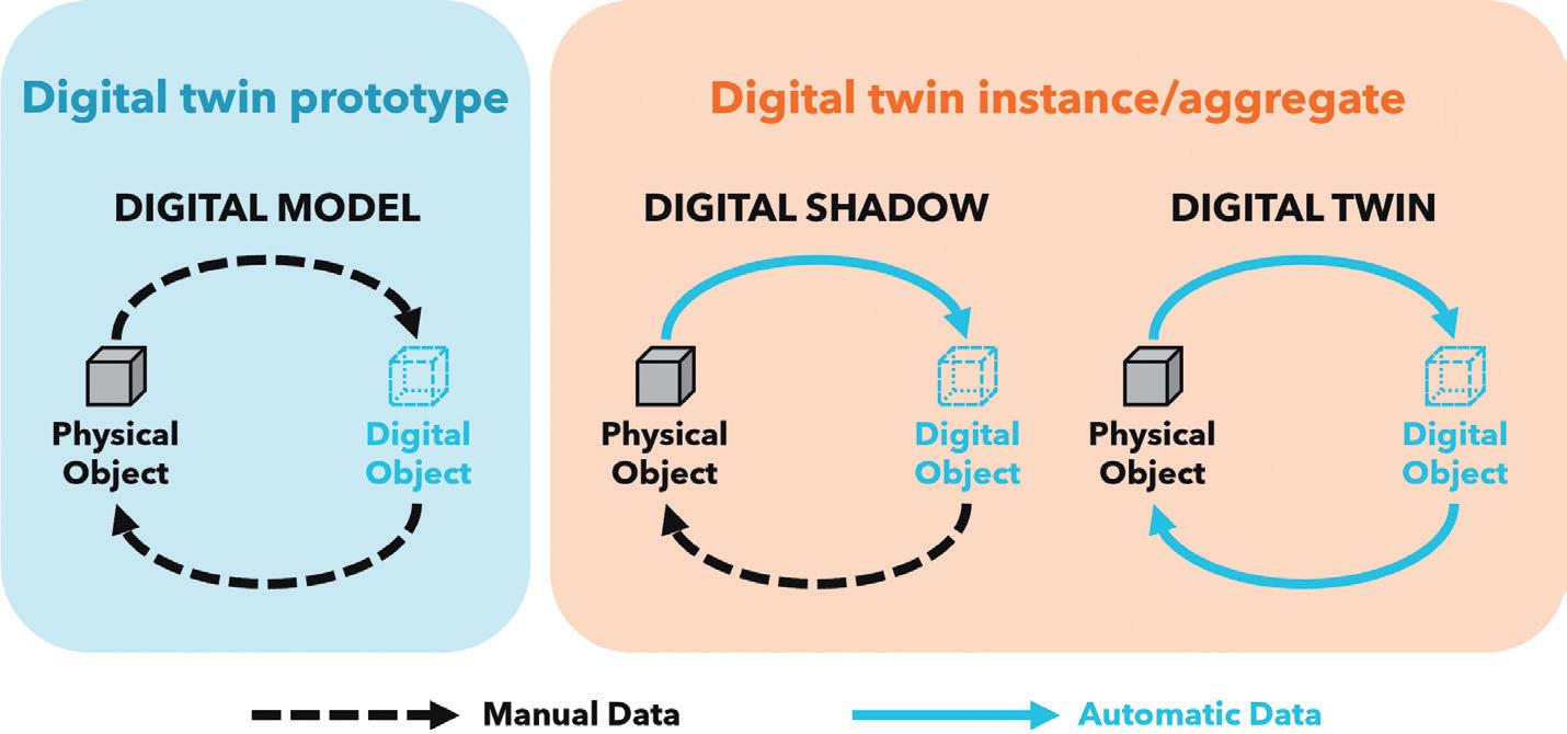
• A digital twin aggregate covers a population of digital twin instances and can be used to understand global behaviour and provide insights across the expected range of tolerances and conditions experienced.
These classifications (Figure 1) provide a framework to enable discussion of the types of digital twin out there, although debate still rages about which of these constitute a “true” digital twin.
Digital twins are a great fit for drug delivery systems and could potentially be deployed at any stage in the product lifecycle. As they offer a data-driven approach to the design, manufacture and deployment of these products, they can achieve gains and improvements not possible with traditional methods.
By leveraging digital twins, engineers and scientists can efficiently iterate design changes, conduct in silico investigations and optimise for key performance indicators, all of which generate valuable insights for
“By leveraging digital twins, engineers and scientists can efficiently iterate design changes, conduct in silico investigations and optimise for key performance indicators.”
advancing system designs, with the added bonus of reduced time to market and lower development costs. Digital twin prototypes used in injectable product development are explored later in this article. Digital twins also offer an amazing opportunity to accelerate drug discovery, simulating the interaction between candidate molecules and the human body to better understand the therapeutic benefit and potential side effects, as well as to personalise dosage and administration frequency.6 Major players in the pharma industry are currently partnering with digital service providers to develop twins for this application.
Beyond the design phase, digital twins offer significant benefits in manufacturing processes. From optimising facility layouts to ensuring operational efficiency, digital twins deployed in the manufacturing environment can increase efficiency, minimise downtime, improve quality and, ultimately, reduce costs.7 They are a key enabling technology behind the shift to smart factories and intelligent industry.
In addition to supplementing the design process and optimising manufacture, digital twins can expand and improve current drug delivery device use cases. With their ability to simulate real-world scenarios and predict performance outcomes, digital twins can, via continuous monitoring, ensure that deployed devices are performing as intended and dynamically make necessary set-up changes if they are not.
One nearer-term possibility might be next-generation control algorithms for electromechanical autoinjectors that use an internal digital representation of
themselves to update operating parameters for greater performance and to deal with novel use conditions. Similarly, such continuous monitoring can also provide medical practitioners with valuable data regarding device usage and patient health to supplement their decision-making process.
A possible future sees drug delivery device digital twins integrated with patient digital twins to optimise therapies digitally and continuously on a case-by-case, day-by-day basis. Of course, much of this is very future-looking and there are significant technical and regulatory hurdles to overcome, similar to the use of artificial intelligence (AI) in healthcare settings, but the potential reward and improvement to patient outcomes is enormous. Full digital twins have the capacity to change how we perceive and interact with drug delivery systems and, ultimately, transform how patients benefit from them.
In the near term, digital twins have the potential to transform the development process for drug delivery systems, reducing development timelines and costs while simultaneously improving development outcomes. Digital twin prototypes can be constructed to assess candidate products and system designs digitally in a virtual use environment long before anything is physically made and tested.
This in silico representation of the proposed system enables rapid iteration and optimisation of designs across an extensive design space, giving greater access to system parameters, conditions, levels of variation and sheer number of test points than could feasibly be realised in a laboratory environment. The simulated product also gives access to a world of data that would be difficult or even impossible to generate physically, which can be used to gain a deeper understanding of the system behaviour. Once this process of iteration and optimisation against stated goals delivers a satisfactory design, the digital twin serves as a blueprint for physical realisation, with parts prototyped and assembled for testing to ensure that performance is adequate and to assess empirical results against the in silico twin predictions.
This holistic system view offers a step change in product development approach, allowing multiple trade-offs
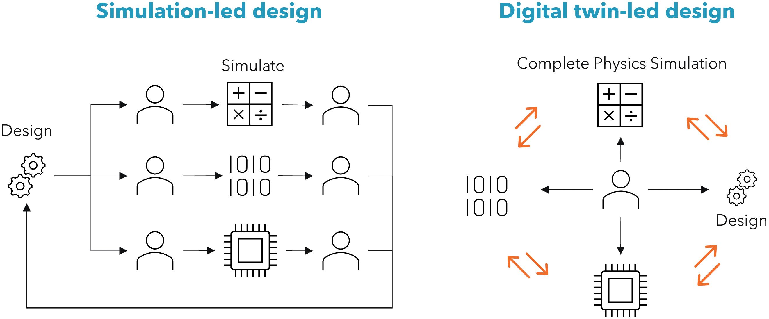
and performance optimisations to be conducted simultaneously, using advanced optimisation routines and AI-enabled development methods. This differentiates digital-twin-led design from simulation-led design (Figure 2), where discrete one-off simulations of specific physical domains are used to inform engineering insight. However, simplifications and assumptions using idealised boundary conditions can lead to errors, and integration of many individual domains may not adequately represent the entire assembled system.
Use of a digital twin prototype during early development can be particularly beneficial. It is estimated that 80% of the product performance (including cost and sustainability) is baked in during the design phase8 – digital twin prototypes allow us to deliver the most meaningful impact at the most impactful time. They also present the opportunity to reduce development costs and timelines, allowing ideas to go from product brief to clinical trial faster, cheaper and with greater confidence than ever before.
Considering their use in injectable device development, the deployment of a digital twin prototype enables the prediction of key aspects of component, sub-assembly and system performance as a linked computerassisted design model is detailed and built up, shortening development timelines and saving physical iterations, but the power also extends far beyond this.
Imagine specifying the ideal motor to perform a set of functions in an electromechanical autoinjector, then substituting in parameters from a real motor specification selected based on
these performance requirements to ensure satisfactory function. Imagine predicting the use life and charging cycle of the battery, based on the full system performance across a range of likely use scenarios and automatically finding an appropriate part for the bill of materials. Imagine defining a loss function to optimise the entire design for formulation delivery performance, cost and sustainability simultaneously.
By way of example, consider specifying an injector spring for delivering the formulation from a drug container through a needle. Traditionally, simply understanding the expected injection force would involve extensive hand calculations, some level of modelling and an assortment of timeconsuming lab tests that are probably not even an ideal substitute for testing in living human skin. With a digital twin prototype, the system can be represented in silico , including the effects of manufacturing tolerances, environmental conditions and so on, then combined with a virtual skin model that can represent a range of patients of different ages, genders and ethnicities, as well as a variety of injection locations. This input space can be explored efficiently to give an estimate of performance over a broad operating envelope, allowing the specification of a suitable component with the confidence that it can handle the full range of expected conditions.
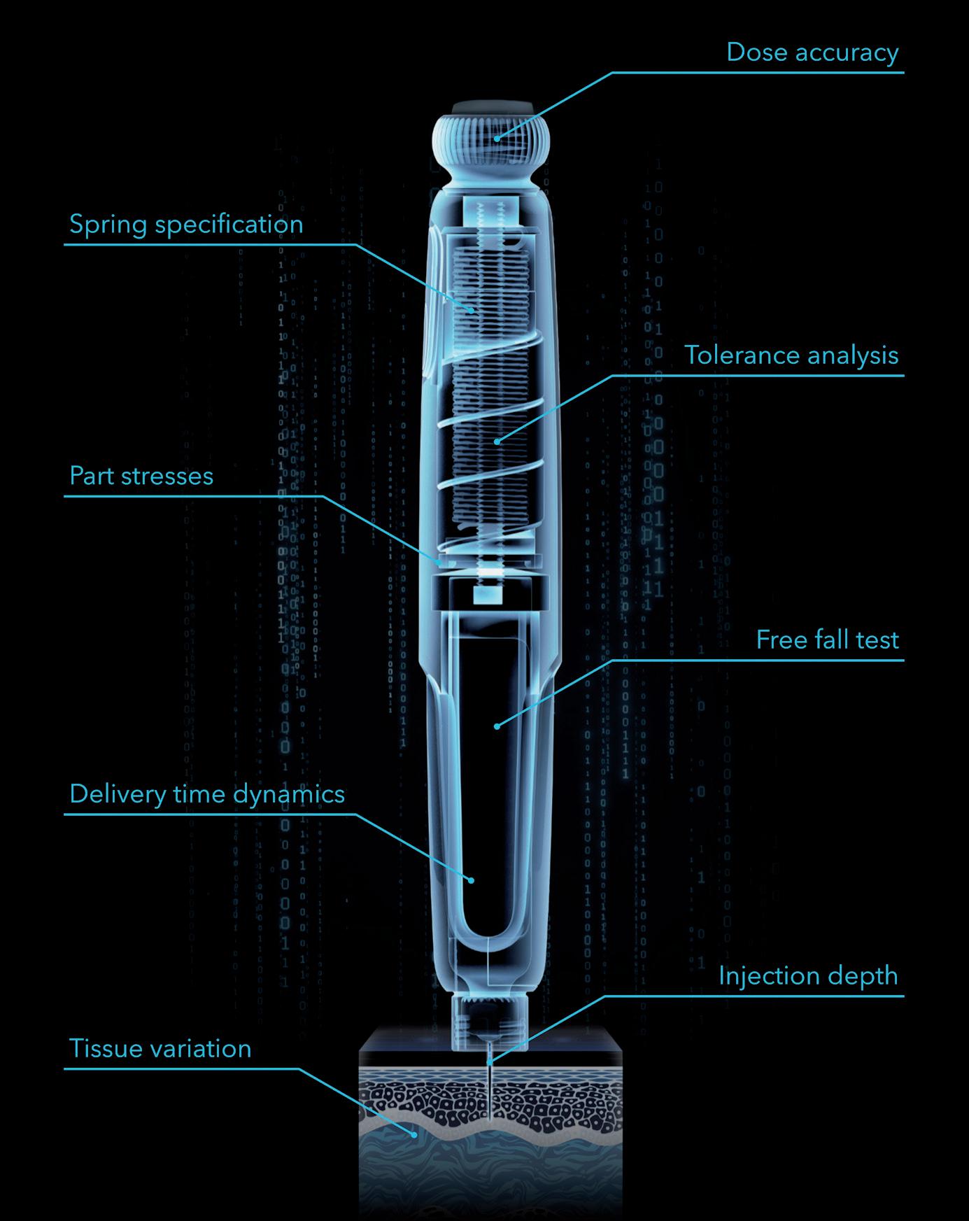
Many standard needle injection system tests demanded by ISO 116089,10 require full devices to be prototyped and tested, which only happens late in the development process. The free fall test, for example, requires the developer to design an expensive
and complicated injector system according to best practice, splitting it into subsystems where great effort is put into each specific area, with hand calculations, single physics simulations and a good measure of engineering experience and judgement. Then tens or even hundreds of parts are painstakingly prototyped at great monetary cost, involving injection mould tools, printed circuit board assemblies, custom springs, etc, before the prototyped design is finally built; at which point it is dropped, it breaks and the test is over – back to the drawing board. If instead, the developer built a digital twin prototype early in development and subjected it to a battery of virtual tests – drop tests, storage conditions, dose accuracy, needle insertion, depth control, injection time, etc (Figure 3), they would have the potential to pre-empt the drop test result and design around it before any parts have been made in the real world. It is possible to pore over the results, performing failure analysis and interrogating part stresses and transient evolution of parameters, and iterate to a robust and reliable design that takes most of the risk out of later physical testing.
“A digital twin can pay
dividends in the range and wealth of data it provides, shortcutting huge chunks of development time and effort.”
There’s no denying that setup and deployment of a digital twin is challenging, with a significant upfront investment of time and effort to define and implement the twin, possibly requiring custom data inputs and targeted characterisation experiments, all of which need to be of adequate accuracy and fidelity, but, once
this has been completed, a digital twin can pay dividends in the range and wealth of data it provides, shortcutting huge chunks of development time and effort. Once a particular application is well-understood, the developed assets, such as tissue models or electronic component representations, can be redeployed on future development
• Time, cost and confidence
• Greater number of iterations
• Optimisation, leveraging of AI techniques
• Repeatability
• Use environment variation
• Interrogation of difficult-to-access variables
• Significant setup and management overhead
• Sourcing of suitable input data and models
• Accuracy of novel environments and phenomena
programmes, expediting them even further. Investment and experience are required to make a success of this, but the potential payback is high (Table 1).
Digital twins offer an amazing opportunity to transform drug delivery devices during development, production and deployment. Digital twins are gaining traction in injectables manufacturing where they can be deployed to minimise losses and improve production efficiency, and the time is right to implement them during the development stage too. This promises to maximise performance gains by designing the right thing first time, all while reducing development timelines, development costs and development risk.
Cambridge Consultants is a deep tech innovation company that develops breakthrough products and services, creates intellectual property and provides business consultancy for technology-critical issues. For more than 60 years, the company has helped its clients turn business opportunities into commercial successes. With more than 800 staff, including engineers, scientists and designers, and offices in Cambridge (UK), Boston (MA, US), Tokyo and Singapore, Cambridge Consultants offers innovative solutions across a diverse range of industries and sectors, including healthcare, digital health, medical technology, drug delivery, life sciences, biotech, industrial and energy, consumer and retail and wireless communications and infrastructure.
1. Frank D, “Digital-Twin Project Green-Lights Traffic Congestion Improvements”. NREL, Jun 8, 2023.
2. “How Digital Twin technology can enhance Aviation”. Web Page, Rolls Royce, Accessed Apr 2024.
3. “The Living Heart Project”. Web Page, Dassault Systèmes, Accessed Apr 2024.
4. Grieves M, Vickers J, “Digital Twin: Mitigating Unpredictable, Undesirable Emergent Behavior in Complex Systems” in “Transdisciplinary Perspectives on Complex Systems” (Kahlen F-J, Flumerfelt S, Alves A Eds). Springer, 2017, pp 85–113.
5. “Digital Twins: Adding Intelligence
to the Real World”. Report, Capgemini, 2022.
6. An G, Cockrell C, “Drug Development Digital Twins for Drug Discovery, Testing and Repurposing: A Schema for Requirements and Development”. Front Syst Biol, 2022, Vol 2, Article 928387.
7. Badiei A, “Digital Twin in the Pharmaceutical Supply Chain.” ONdrugDelivery, Issue 149 (Jun 2023), pp 45–58.
8. “Circular economy action plan”. Web Page, European Commission, Accessed Apr 2024.
9. “ISO 11608-1:2022 Needle-based injection systems for medical use: Requirements and test methods
Part 1: Needle-based injection systems”. International Organization for Standardization, Apr 2022.
10. “ISO 11608-5:2022 Needle-based injection systems for medical use: Requirements and test methods
Part 5: Automated functions”. International Organization for Standardization, Apr 2022.
Dan Cowen is a physicist specialising in fluid and thermodynamics, engineering simulation and numerical modelling, with particular experience simulating complex fluid systems using computational fluid dynamics. He has significant experience leading large multidisciplinary medical development programmes, including respiratory and parenteral drug delivery devices, and is a MedTech sustainability lead. Mr Cowen has worked in the medical sector for the past eight years, prior to which he worked in the consumer products industry where he successfully delivered 20 products to market.
Sebastian White is a Principal Engineer specialising in computational modelling. With over five years of experience in the Medical Technology industry, Mr White couples advanced computational modelling techniques with sound engineering practices to develop complex medical devices. Before joining Cambridge Consultants, Mr White held roles in the Bank of England and RedBull Racing’s aerodynamics department. He holds a 1st class master’s degree in Mechanical Engineering from Loughborough University (UK).
Anthony Robinson has 17 years’ experience in both consultancy and original equipment manufacturer environments, Mr Robinson has a broad range of skills with specialist knowledge in structural mechanics, mechanism design and analytical engineering across multiple industries. He uses this specialist knowledge to build finite element analysis, rigid body dynamics and transient dynamic simulations to develop device-level digital twin prototypes that are used to evaluate and evolve complex drug delivery devices and shortcut long and iterative device prototyping cycles.

In this article, Jeff Clement, Executive Director, Technical Sales – Development and Manufacturing, and Bill Welch, Executive Director of Services, both at PCI Pharma Services, explore the essential considerations for navigating the parallel development of a drug product in a vial and a prefilled syringe for an autoinjector, together with the downstream final assembly and pack considerations, from early-phase clinical trials to commercialisation.
The journey from early-phase clinical trials to successful commercial launch for an injectable drug product is complex and multifaceted. When considering the delivery system, the choice between a traditional vial or prefilled syringe (PFS) and a modern autoinjector can significantly impact the patient experience, adherence and market competitiveness. Parallel development of both vials and PFSs for autoinjector options requires careful consideration to ensure regulatory compliance, patient safety and commercial success.
Traditionally, for intravenous (IV) administration of a drug product, either a single or multi-use vial would be the primary container of choice for biopharmaceutical companies during preclinical and earlyphase clinical trials. With the primary objectives being proof of concept, safety and tolerated dose, vials present a high degree of flexibility with respect to fill volume and applied dose, supporting the immediate need for speed through the clinic.
However, with the modern focus on patient centricity and the increasing adoption of self-administration devices across various therapeutic areas for
anaphylaxis, allergies and chronic diseases such as psoriasis, diabetes, multiple sclerosis and rheumatoid arthritis, biopharmaceutical companies are actively incorporating patient-viable subcutaneous (SC) dosage forms, such as PFSs and autoinjectors, into their product portfolios.
Due to companies recognising the competitive advantage these devices offer in terms of differentiation, patient compliance and patient satisfaction, the autoinjector market is witnessing a surge in innovation. Biopharmaceutical companies are not only investing in research and development to enhance device features and compatibility with a diverse range of large- and smallmolecule drug products, but they are also introducing and evaluating them as viable dosage forms earlier in clinical trials.
Changing the method of administering a treatment during clinical trials, such as changing from IV to SC delivery and introducing a combination product, brings added complexity to both technical and clinical development plans. This necessitates additional clinical bridging studies, including assessments of bioavailability and

Jeff Clement
Executive Director, Technical Sales –Development and Manufacturing E: jeff.clement@pci.com

Bill Welch
Executive Director of Services E: bill.welch@pci.com
PCI Pharma Services 3001 Red Lion Road Philadelphia PA 19114
United States www.pci.com
safety, as well as technical comparability studies if adjustments are made to the concentration, pH, tonicity or other critical quality attributes of the formulated drug product, which will add time and cost to the development programme. To address these challenges, biopharmaceutical companies are looking to parallel development strategies.
Parallel development in early-phase clinical studies involves concurrent and co-ordinated advancement of both drug and container/device components from early stages through to commercialisation. With the key objective of accelerating time to market, close collaboration between pharmaceutical development and injectable device packaging teams is essential to align goals and streamline processes.
Parallel container studies are conducted during the development of drug products to compare the performance, stability and compatibility of the product when packaged in different container types. Evaluating multiple container closure system configurations early in the development lifecycle provides optimum flexibility and accelerates speed to market.
Specifically, when considering drug products packaged in vials versus PFSs, parallel container studies aim to assess any differences in factors such as stability, container-material interactions, drug product integrity and usability. These studies involve packaging the same formulation of the drug product into both vials and PFSs and subjecting them to a series of tests and evaluations. The following tests are some key aspects of parallel container studies for drug products in vials and PFSs.
Both vials and PFSs are subjected to stability testing under various storage conditions (e.g. temperature, humidity) to evaluate the degradation kinetics of the drug product. This helps determine whether there are any differences in stability between the two container types. Putting both vials and PFSs down for stability during earlyphase trials provides access to more than two years of stability data compared with beginning only with a vial format. So, even if clinical trials are being conducted using a vial, stability data is being collected simultaneously on PFS presentations, buying time for later-phase trials.
Similarly, autoinjector functional stability tests following ISO 11608-5, such as cap removal force, activation force, extended needle length, dose accuracy, injection time and lockout force, can be conducted in parallel, saving valuable time should a decision be made in laterphase trials to proceed with this method of drug delivery.
These studies assess the compatibility of the drug product with the materials used in vials and PFSs. They aim to identify any interactions between the drug product and the container that could affect product stability, efficacy or safety. Photo-stability studies should also be initiated to evaluate drug product sensitivity to light.
The most critical aspect of primary packaging is for it to be as inert as possible so that it does not react with, add to, absorb or allow external factors to change a drug product’s established safety, strength, quality, stability or purity characteristics. The material must be chemically stable, support the required concentration of the drug, not cause any extractables or leachables issues and not delaminate or undergo other changes upon contact with the drug product.
Container closure integrity (CCI) is critical for maintaining the sterility and stability of the drug product. Both vials and PFSs undergo testing to ensure that the container closure system combination effectively prevents contamination and leakage. CCI testing may be conducted in parallel with autoinjector functional stability testing.
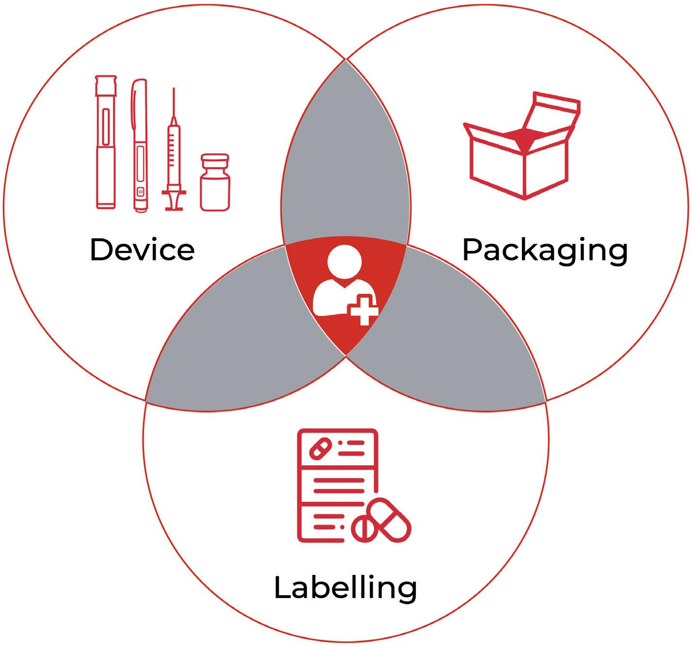
Parallel studies may also include assessments comparing usability and patient preference between PFSs and autoinjectors. Factors such as ease of handling, convenience and patient comfort are evaluated to determine which container type may be preferred by end users. With a focus on patient centricity, assessing the interaction between users and the product, as received, is paramount. Understanding how patients and healthcare professionals interact with the packaging, instructions for use (IFU) and the device itself is vital for optimising usability, minimising user errors and enhancing overall safety, efficacy and adherence to achieve improved outcomes (Figure 1). Conducting usability studies and incorporating human factors considerations early in the design process can help identify potential issues and inform design
modifications. Human factors and usability engineering is an integral component of regulatory submissions and is essential for demonstrating a product’s usability and user comprehension.
Parallel container studies are conducted in compliance with regulatory guidelines, which may vary depending on the geographic region. Regulatory authorities require comprehensive data demonstrating the comparability and suitability of both container types for the intended drug product.
The benefits of parallel development include:
• Expedited Timeline: Running drug and device development activities in parallel can significantly reduce the overall time to market by eliminating sequential processes and optimising workflows.
• Enhanced Efficiency : Co-ordinated efforts and shared resources can lead to improved efficiency in development activities, resulting in cost savings and faster decision making. Streamlining processes and workflows can lead to improved efficiency in resource use and decision making.
• Regulatory Alignment : Aligning regulatory strategies for both drug and device elements early in the development process facilitates smoother regulatory approval and market entry.
• Cost Savings : eliminating redundant activities and optimising resource allocation can result in overall cost savings throughout the development lifecycle.
Parallel container studies provide valuable insights into the performance of drug products in vials and PFSs, helping biopharmaceutical companies make informed decisions regarding primary
packaging choices based on factors such as stability, compatibility and patient preferences – avoiding costly delays on the journey to commercialisation.
Data gathered and analysed during parallel container studies in early clinical trials eases the transition to PFSs for later-phase clinical trials. Typically, in Phase IIb clinical trials, biopharmaceutical companies seek to make decisions on the therapy’s drug-device strategy – whether to continue with the PFS as is, convert to a needle safety device or insert it into an autoinjector to provide ultimate flexibility for various healthcare professionals, patient populations or reimbursement schemes.
Considering the target product profile and quality target product profile, decisions can be made on whether there is a unique need for device innovation for specific patient populations or if traditional, readily available platforms would be suitable. Selecting established platforms that have already received regulatory approval as part of a drug-device combination product may be deemed lower risk for a new programme (Table 1).
Established platform
Proprietary platform
• Lower upfront costs
• Leverage of existing capital infrastructure
• Smoother regulatory path
• Robustness of device uses currently in the market
• Product differentiation –competitive advantage
• Custom design for specific applications
• Extends intellectual property life of the product
• Lower unit costs when scale is achieved
“Data gathered and analysed during parallel container studies in early clinical trials eases the transition to PFSs for later-phase clinical trials.”
To avoid unnecessary delays and additional costs, consultation between developers and clinical and commercial stakeholder groups is important throughout the parallel development lifecycle. Packaging design is a critical area of importance, so early consideration of manufacturability is encouraged. Considering package design earlier in the drug development process can lead to both cost and time efficiencies as the cost of mistakes can be considerable and delay product launch milestones. By ensuring that design and operational teams work together and apply a design for manufacture philosophy, the teams
• Limited product differentiation
• Higher unit costs
• Coemption of supply for popular devices
• Higher upfront costs (e.g. design, IP, capital technology)
• Complex regulatory path
Table 1: The advantages and disadvantages of established versus proprietary platforms.
www.ondrugdelivery.com/subscribe
will understand the impact of design on packaging operations earlier in the process, delivering a streamlined and longer-term efficient solution.
A common challenge often arises when a biopharmaceutical company has had its packaging designed by a third-party design agency, which may fit the enduser specification and sponsor’s branding requirements but does not fit on existing packaging infrastructure when it comes to commercial manufacture. A design that is not optimised for the packaging process equipment will result in unnecessary upfront capital costs, modifications to existing equipment and higher labour and commercialisation costs, ultimately resulting in higher manufacturing costs and lower commercial revenues.
With many critical considerations when conducting parallel development of a novel drug product in vials and PFSs for autoinjectors, there are several best practices that can help ensure a smooth and efficient process, including:
• Early Collaboration: It is important to establish cross-functional teams of all stakeholders involved in the development process, including formulation scientists, packaging engineers, regulatory experts, quality assurance professionals and patient focus groups. Fostering collaboration and communication from project initiation ensures alignment of goals, troubleshooting and efficient progress.
• Risk Management : Proactively identifying and addressing potential
“From early-phase clinical trials to successful commercial launch, considerations such as drug product device compatibility, manufacturability and packaging design must be carefully navigated.”
risks, such as technical challenges or regulatory hurdles, can help mitigate delays and ensure project success.
• Iterative Development : Embracing an iterative approach allows for continuous refinement and optimisation based on user testing, regulatory feedback and market insights.
• Regulatory Compliance : It is critical to ensure compliance with regulatory requirements for vials, PFSs and autoinjectors in the target markets. This includes adherence to relevant guidelines for drug product packaging, device design, quality control and documentation.
• Flexibility and Adaptability: Maintain flexibility and adaptability throughout the development process to accommodate any unforeseen challenges or changes in project requirements. Be prepared to adjust timelines, resources and strategies as needed to optimise the parallel development of vials and PFSs for autoinjectors.
Parallel development has emerged as a strategic approach to expedite the development process and bring innovative therapies in drug-device combination products, such as autoinjectors, to
market faster. From early-phase clinical trials to successful commercial launch, considerations such as drug product device compatibility, manufacturability and packaging design must be carefully navigated. By addressing these considerations proactively and strategically, biopharmaceutical companies can streamline their clinical to commercial process and, ultimately, improve patient outcomes.
PCI Pharma Services is a leading global CDMO, providing integrated end-to-end drug development, manufacturing and packaging solutions to increase product speed to market and opportunities for commercial success. PCI Pharma brings the proven experience that comes with more than 90 successful product launches each year and over five decades in the delivery of supply-chain healthcare services. With 30 sites across Australia, Canada, North America, the UK and Europe and over 5,500 dedicated employees, the company’s mission is to bring life-changing therapies to patients. Leading technology and continued investment enable PCI to deliver development to commercialisation solutions throughout the product lifecycle, collaborating with its clients to improve the lives of patients globally.
Jeff Clement joined PCI Pharma Services in 2014. In his current role of Executive Director, Technical Sales – Development and Manufacturing, he provides technical drug product development and manufacturing support to PCI’s global business development teams. Mr Clement has over 25 years in the biotech and pharmaceutical industries and his career includes experience in the pharmaceutical discovery sciences, high throughput automation, clinical formulation development and cGMP analytical and manufacturing contract services. All his business development experience is in the aseptic manufacturing and analytical fields. Prior to his current role, Mr Clement was the Director of Global Business Development at Curia (Drug Product). Mr Clement received a BS in Biology from Keene State College (NH, US) and an MS in Quality Systems from The New England College of Business (MA, US).
Bill Welch is Executive Director of Services for PCI Pharma Services’ advanced drug delivery business segment, with a focus on injectable drug-device combination products. Mr Welch has over 30 years of contract development and manufacturing experience, with over 20 years in drug delivery devices and combination products. Prior to joining PCI, he served as Chief Technology Officer at Phillips-Medisize, leading a 900-person global innovation, development and new product introduction service segment. Mr Welch holds a BS in Industrial Engineering from the University of Minnesota Duluth (MN, US).

In this article, Nicky Bertollo, PhD, Chief Technology Officer & Co-Founder, Adam Rock, Strategic Partnerships and Commercialisation Manager, and Ronan Byrne, Chief Executive Officer & Co-Founder, all at Pharma Latch, discuss the benefits and limitations of intradermal delivery – and introduce the Pharma Latch Hollow intradermal injection device.
Intradermal (ID) delivery has long been considered an attractive alternative to traditional parenteral delivery strategies for a variety of drug modalities. Compared with other parenteral targets (e.g. muscle or subcutaneous tissue), the skin is more readily accessible and replete with a vast repertoire of immunocompetent cell types (e.g. dendritic cells) whose activation is considered a primary and essential step in effective immunisation. Additionally, the rich innervation of vascular and lymphatic vessels ensures rapid trafficking of immune cells and other macromolecules (e.g. biologics) to the wider circulatory system. These features translate into numerous, well-established benefits, including:
• For vaccines, functional improvements in the durability, strength and type of immune response following vaccination
• Non-inferior immune responses with fractional dosing (i.e. dose sparing)
• For biologics, improved pharmacokinetic profiles (increased bioavailability, faster onset of action, increased Cmax/Tmax, etc)
• Reduced needle phobia from shallow needle penetration.
Drug Delivery Limitations Typically Associated with Intradermal Delivery
Despite these benefits, however, ID remains a chronically underused route of administration (ROA), underserved by a lack of efficient, reliable and versatile delivery device technologies or injection methods. For example, the Mantoux technique (clinician inserting a needle into the skin at an angle) – first described more than 100 years ago – still remains the clinical standard for performing ID injections.
This procedure is technically challenging to perform, as the approach angle and depth of needle penetration are user-dependent and therefore subject to a high degree of variability. In fact, it has been demonstrated that up to 70% of ID injections administered using this technique are delivered to the incorrect depth (i.e. not intradermally).1 Subsequently, a number of drug delivery technologies have been developed over the years to improve the ease of dermal delivery (e.g. jet injections and hollow, hypodermic and microneedle systems), however, these have achieved limited clinical and commercial success. Often, they struggle in some or all of the following areas:
• Reliably administering to the correct depth in the skin
• Regulatory concerns over consistent dose administration
• Lack of confidence for the administering healthcare professional (HCP)
• Typically very low volume and viscosity capabilities
• Difficulties around scale-up and manufacturing.
The Pharma Latch Hollow (PLH) is an intradermal injection device based on the “Latch” platform of opposing angled hypodermic needles. This novel injection platform facilitates simple, precise and repeatable intradermal injections, allowing the ID ROA to be a truly viable option for the pharmaceutical industry for the first time. Furthermore, the combination of a unique fluid pathway and favourable manipulation of the biomechanical properties of the skin, allows the Latch platform to inject high volume and

Dr Nicky Bertollo Chief Technology Officer and Co-Founder
E: nicky@latch-medical.com

Adam Rock
Strategic Partnerships and Commercialisation Manager E: adam.rock@latch-medical.com

Ronan Byrne Chief Executive Officer and Co-Founder
E: ronan.byrne@latch-medical.com
Pharma Latch NovaUCD
Belfield Innovation Park Belfield Dublin 4 D04 V2P1
Ireland
www.pharmalatch.com
“The dermis, however, due to its finite thickness, superficial anatomical location and viscoelastic properties, poses additional challenges that have yet to be adequately addressed.”
viscosity formulations (up to 3 mL, 60 cP), increasing the clinical applications of ID delivery beyond what was previously thought possible. This novel injection platform facilitates the development of a pipeline of future autoinjector and selfinjection combination products (currently under development) that can address the complex delivery challenges of therapeutics for the management of chronic diseases.
For an ID injection to be considered successful, it must achieve full penetration of the needle lumen to a precise depth in skin. Furthermore, the position of the needle must be maintained during the injection in order to ensure complete dose delivery to the intended depth and avoid leakage. Similar principles apply to intramuscular (IM) and subcutaneous (SC) injections but, in those cases, the physical target tissue is sufficiently bulky and deep from the skin surface – easily satisfying these targeting requirements. The dermis, however, due to its finite thickness, superficial anatomical location and viscoelastic properties (that are inherently resistant to puncture), poses additional challenges that have yet to be adequately addressed.
Current convention for performing ID injections uses a combination of techniques and devices that can be grouped into three main categories, as follows:
1. Using a 27G needle (i.e. Mantoux technique)
2. Employing devices exhibiting fixed-length needles applied perpendicularly to skin
3. Using microneedle-based devices applied at an angle to the skin surface.
Figure 1 illustrates the challenges posed by the skin with each approach. In each case, application of the needle/device to the skin is associated with uncontrolled skin compression and deformation, leading to the establishment of skin “tenting”. Effectively, this relates to the extent to which skin deforms before and during needle puncture. This tenting phenomenon further compromises the ability of the clinician to precisely and repeatably reach the target depth, as the underlying layers of the skin are also compressed or “sandwiched” together. Furthermore, excessive compression reduces the volumetric capacity of the injection site, causing reduced tissue distribution and increased injection pressures. As such, there is an increased likelihood of spray-back or injection site leakage, as well as injection volume limitations. Additionally, tissue compression and increased injection pressure can activate the deep mechanoreceptors of the skin, generating pain and discomfort for the patient. From a usability perspective, mounting injection pressures increase the difficulty of performing the injection, causing significant burden and discomfort to the clinician.
These complications are further exacerbated by factors affecting the mechanical behaviour of skin (including age, race, sex, illness and comorbidities) and by
the formulation of the injectate. Ultimately, current injection techniques and devices do not adequately address the biomechanical properties of the skin. As such, they:
• Deliver doses to incorrect depths and compartments in the skin – compression and tenting of skin results in variable targeting
• Must have low viscosity and volume combinations – typically 100–250 μL or less and – are largely only aqueous-based formulations
• Are difficult to administer – significant training is required to perform them and experience is needed to master each approach
• Require significant syringe forces that further complicate usability – high syringe plunger loads are required to pressurise and force the injection into mechanically compressed tissue
• Have high injection pressure requirements that, coupled with skin tenting, can leave the needle lumen open to atmosphere, resulting in a wet injection or spray-back of the injectate onto the patient and/or clinician
• Cause pain and discomfort for the patient – compression of skin activates skin mechanoreceptors, resulting in increased pain and discomfort, further exacerbated by high-pressure fluid flow in mechanically-compressed tissue (hydrodynamic effect).
Accordingly, the potential therapeutic benefits of ID delivery are yet to be realised. In addition to working in traditional vaccine applications, Pharma Latch can be effective in a range of new combinations and next-generation therapies, such as cancer immunotherapies, cell-based therapies, biologics and vaccines for prophylaxis and for chronic conditions.
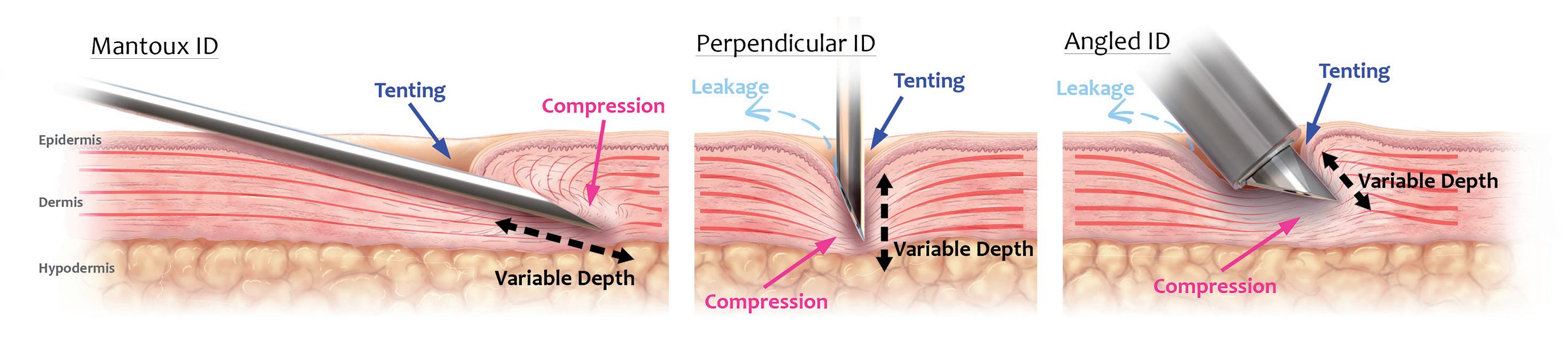
For all approaches,
in “tenting” and compression, resulting in poor needle insertion efficiency and lack of precise depth control and unconfined skin compression. The ability to administer the full dose to the correct depth and compartment in the skin is further compromised by the requirement for high injection pressures, which can result in leakage and spray-back.
Having identified the biomechanical challenges posed by the skin and the established and emerging drug modalities that could benefit from ID delivery, Pharma Latch developed a hollow-microneedlebased technology platform capable of addressing the existing shortcomings of ID delivery. Its first product offering built off the platform –the PLH – is in development as an HCP-administered, sterile-packed, single-use, disposable medical device to be used for ID injection of drugs and vaccines approved for that ROA (Figure 2).
Currently under development as a Class II US FDA medical device (i.e. 510k pathway), the PLH is designed to be:
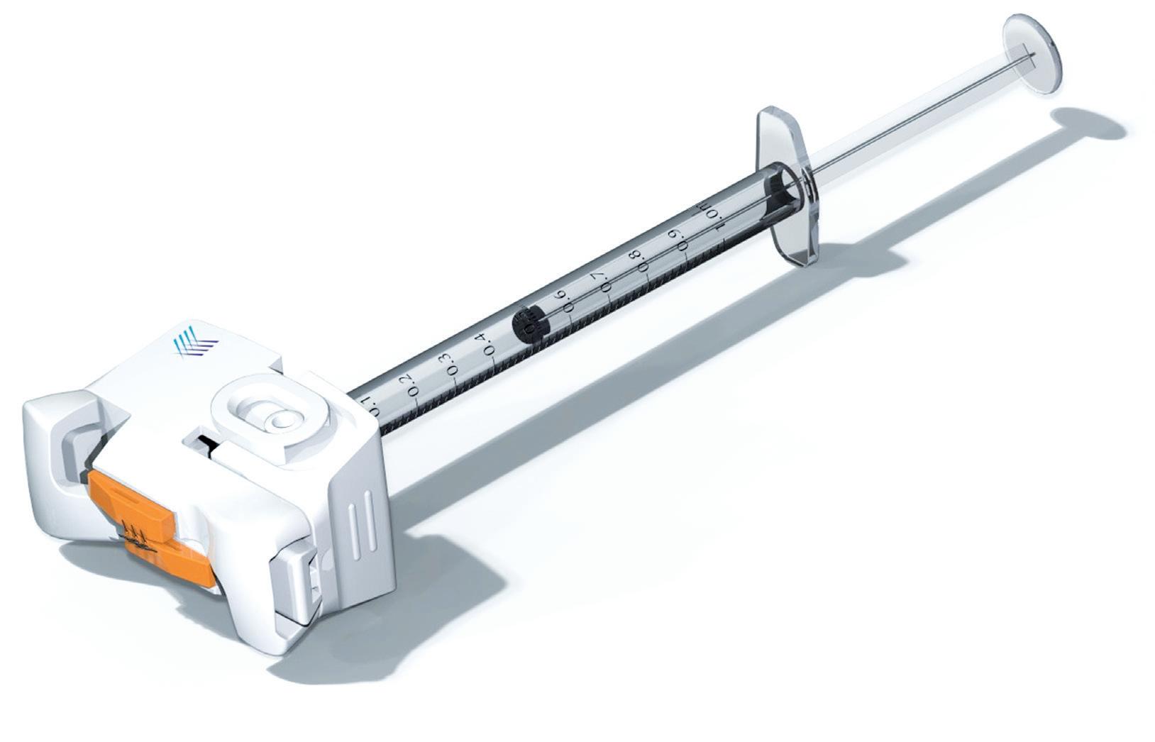
• Compatible with existing parenteral workflows
• Integrable with prefilled or pre-drawn Luer lock/slip syringe barrels.
At its distal end, the PLH exhibits two arrays of three angled 31G hypodermic
needles set into the device, all of which are in fluid communication with the attached syringe. Figure 3 depicts the steps involved in administering an ID injection using the PLH.
In a first step, the device is placed over the injection site until shallow indentations are formed on the skin, which can be any anatomical site accustomed to receiving parenteral injections. Maintaining this
Figure 2: Overview of the PLH, which is being developed as a single-use, sterile-packed, HCP-administered medical device. The PLH is compatible with both Luer lock and clip syringes, and exhibits arrays of angled 31G hypodermic needles at its distal end for delivery of the injectate into the dermal layer.
downwards pressure, the needles of the device are then deployed into the skin using a simplified “clicking” or squeezing action. This resulting linear motion of the angled hypodermic needle tips, which are in an initial state of overlap, applies subtle stretch to the tissue, keeping the skin taut and preventing skin from tenting and compressing during needle insertion and propagation.
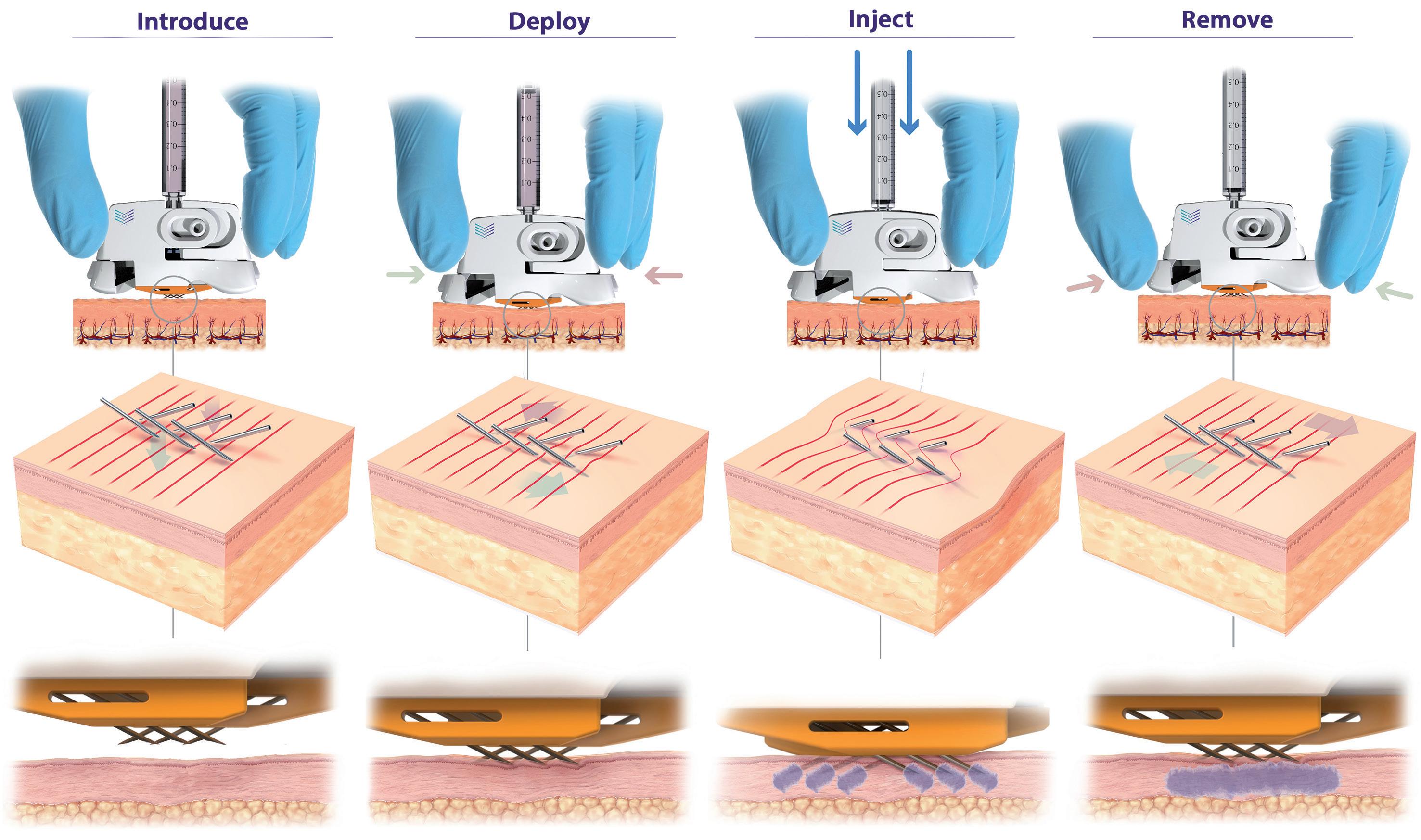
3: PLH operation (left to right). Device is placed over the injection site. The needles are then deployed using a simple “clicking” action, which establishes a slight stretching of the skin, preventing tenting and compression and enabling full penetration of the hypodermic needles to a predetermined depth (820 μm). Injection can be performed with minimal resistance and with superior diffusion into uncompressed tissue. The PLH can then be removed from the skin, using simple squeezing of the release tabs, and disposed of.
Highly efficient needle insertion mechanics are achieved, requiring low needle insertion forces, resulting in reduced pain and discomfort for the patient compared with existing approaches. At the final step, with the injection administered, by applying an intuitive clicking action to the release tabs, the PLH can be removed from the skin and disposed of accordingly.
This method of needle insertion, unique to the PLH, ensures:
• Precise needle penetration, with the tips of the hypodermic needles, which are at a fixed vertical height from the device, delivered to a predetermined, precise, repeatable depth (circa 800 μm) into the skin with each application
• Dramatically reduced skin deformation and compression, offering a step change in diffusion compared with standard approaches and devices
• Low injection pressures and syringe barrel forces, as distribution of the injectate takes place across all six 31G hypodermic needles into uncompressed skin, greatly improving usability.
Internal testing (data on file) for the PLH has shown superior syringeability and injectability compared with a single 27G needle and competitor devices. In terms of syringeability, 4x and 6x reductions in injection back pressure at flow rates of 1 mL/min and 10 mL/min, respectively, using a low viscosity standard (1.2 cPs) were achieved for the PLH compared with a single 27G needle. For the competitor product, the reduction at 1 mL/min and 8 mL/min was 8x and 20x, respectively. Testing had to be stopped for the competitor device at flow rates higher than 8 mL/min due to excessive back pressures.
Further injectability studies in a combination of in vitro and in vivo preclinical large animal tests with several partners (data on file) have confirmed the ability to deliver large injection volumes (up to 3 mL) and achieve superior diffusion and improved usability compared with conventional ID approaches.
“PLH
dramatically simplifies the procedure for the user and removes the variability associated with traditional techniques by having device geometry –and not the user – govern needle insertion depth.”
In summary, PLH offers an ID delivery device solution that:
• Can deliver the full dose to the correct layer in the skin for every patient
• Is able to work with both low and high volume/viscosity formulation combinations
• Has low injection back pressures, eliminating the potential for leakage and spray-back
• Reduces needle anxiety, pain and discomfort, and improves the patient experience
• Is intuitive, simple to use and easy to administer
• Attaches securely to the skin, providing confidence in administration
• Has a highly scalable manufacturing roadmap, capable of being deployed as a medical countermeasure and futureproofing rapid pandemic responses.
PLH introduces a new and improved device-based solution for injecting liquid formulations into the skin, achieving this in a number of different ways. Firstly, PLH dramatically simplifies the procedure for the user and removes the variability associated with traditional techniques by having device geometry – and not the user – govern needle insertion depth. Secondly, through a combination of favourable conditions that are established in the skin and inherently low internal fluidic resistance, PLH provides ease of injection and can work with volumes (>1 mL) and viscosities (up to 60 cPs) that were previously only achievable with IM and SC administration. Thirdly, PLH can ensure full dose delivery consistently and repeatedly in all patients,
thereby satisfying clinicians and regulators, alike. Finally, compared with conventional approaches, PLH improves the patient experience by reducing needle anxiety, pain and discomfort, thereby improving and driving compliance.
PLH provides a reliable device solution for ID administration that can support and remove the device/delivery risk from preclinical and clinical development programmes. Additionally, PLH is being built on a core platform technology that supports the development of a pipeline of future self-injection and autoinjector products to complement the PLH product. These future Pharma Latch products have the potential to meet the complex delivery needs of therapeutic modalities in development for the at-home treatment of chronic diseases, and where ID delivery is increasingly being recognised as having an important role to play.
Pharma Latch is a venture and corporate (West Pharmaceutical Services) funded medical device company based in Dublin, Ireland. The company has developed a unique portfolio of HCP and self-administration
“PLH provides ease of injection and can work with volumes (>1 mL) and viscosities (up to 60 cPs) that were previously only achievable with IM and SC administration.”
intradermal injection devices, based on a core platform technology. Its core platform technology uses an array of opposing-angled microneedles that latch into the skin at a preset depth, ensuring consistent needledepth penetration and dose delivery, every
time. Its devices can deliver high volumes (>3 mL) and viscosities (>60 cP) and are simple to use, cost efficient and highly scalable. Furthermore, the use of microneedles overcomes issues surrounding needle anxiety, significantly improving patient compliance.
1. Micheels P, Goodman L, “Injection Depth in Intradermal Therapy: Update and Correction of Published Data”. J Drugs Dermatol, 2018, Vol 17(1), pp 88–96.
Nicky Bertollo, PhD (University of New South Wales, Sydney, Australia), is Chief Technology Officer and Co-Founder of Pharma Latch. He is a biomedical engineer with over 15 years’ experience in the design, development, preclinical testing and evaluation of medical devices. Dr Bertollo is the inventor of the Latch platform technology and has built deep domain expertise in intradermal drug delivery technologies over a number of years. Dr Bertollo leads all the company’s engineering, technical and scientific activities.
Adam Rock is Strategic Partnerships and Commercialisation Manager at Pharma Latch. Mr Rock’s core interest and expertise is around identifying and evaluating high-value partnership opportunities across the pharmaceutical and drug delivery industry. Prior to joining Pharma Latch, he spent a number of years in a research setting, focused on drug development at various institutes including The Francis Crick Institute in London, UK. Mr Rock holds a Masters by Research (MRes) in Drug Discovery and Development from Imperial College London, and a BSc (Hons) in Pharmacology (University College Dublin).
Ronan Byrne is Chief Executive Officer and Co-Founder of Pharma Latch and has been a commercial leader of multiple companies over the last two decades. His specialty is commercialising innovative medical technologies. Prior to Pharma Latch, Mr Byrne founded, built and led the development of ophthalmic diagnostics company ClearSight Innovations, which was sold to a global industry leader. Over the last few years, Mr Byrne’s focus has been on realising the potential of Pharma Latch and delivering a paradigm shift in the intradermal drug delivery space.


Here, Cécile Gross, Global Category Manager, Parenteral, and Mark Tunkel, Global Category Director, Services, both at Nemera, discuss the variety of pen injector platforms to meet the different needs of diabetes patients.
Not a day goes by without reading in the newspapers an article on diabetes or obesity. A new word has also recently appeared: diabesity. It actually dates back to the 1970s when Ethan Sims originally used the term to describe studies in which healthy prisoners were deliberately overfed to gain weight and become overweight, but not obese. The aim was to demonstrate reversible rises in fasting glucose and a deterioration of glucose tolerance, not diabetes.
The former American Diabetes Association President Francine Kaufman, amongst others, has used this term since then to describe the co-existence of the twin pandemics – and the term spread. Exactly like the obesity pandemic itself. In 2022, the WHO estimated that one in eight people are living with obesity,1,2 showing a huge increase in adults and a massive increase in teenagers, which led to the acceleration of the WHO’s plan3 to stop it. This has been substantiated by a new study released by The Lancet4 – stating that more than 1 billion people in the world are living with obesity.
“Healthcare systems, buying powers and cultural habits differ between the US, Europe and India and will lead to differentiated offerings to meet patients’ needs.”
Diabetes is a worldwide health problem, and combining this condition with underweight or obesity adds to the burden on patients even more. This reflects the intricate relationship between complex chronic diseases and their snowball effects in today’s world.
Looking at available treatments for diabetes, insulin has been known and used for more than 100 years and, more recently, peptides such as glucagon-like peptide 1 (GLP-1) have also been used. Since the first US FDA-approved GLP-1 in 2009, pharma companies have worked to reduce injection frequency, improve the drug delivery device and even offer diverse administration routes, such as oral delivery. Although limited to Type 2 diabetes, they offer patients the possibility of having less-frequent injections. Obesity patients can now benefit from them as an alternative to bariatric surgery (Figure 1).
However, patients cannot be considered as one homogenous group: there is a discrepancy in incidence between women and men, adults and teenagers, and geography is also adding to the complexity of care. As an example, healthcare systems, buying powers and cultural habits differ between the US, Europe and India and will lead to differentiated offerings to meet patients’ needs. As a drug delivery device manufacturer and combination product service provider, Nemera’s responsibility is to consider these characteristics and implement them into its devices.

Cécile Gross
Global Category Manager, Parenteral E: cecile.gross@nemera.net

Mark Tunkel
Global Category Director, Services E: mark.tunkel@nemera.net
Nemera 63 Avenue Tony Garnier 69007 Lyon France
www.nemera.net
journey research
better understand a specific patient population, tailoring solutions to answering the unmet needs.
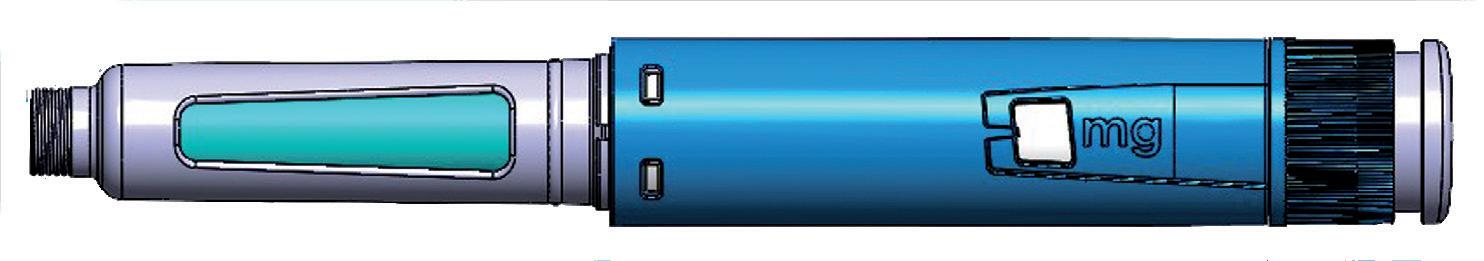
US patients, for example, usually perform unit-dose injection with a disposable device. Given the relatively high volume per dose to be injected, it implies a spring-assisted injection. European patients still need to perform a high-volume injection, but they will use either a unit-dose or a multiple-dose disposable delivery device. In both cases, injection is spring assisted. Indian patients are very sensitive to cost per injection; therefore, they would rather use a multipledose delivery device. Mostly they opt to use reusable devices as they are much more cost effective, whilst some others may still prefer to use manual disposable ones.
PenSET and PenDIA
The PenSET and PenDIA (Figure 2) platforms can accommodate GLP-1 drugs with a smooth spring-assisted injection. A multiple-dose device has been chosen rather than a unit-dose one to alleviate the burden on the patient. Having one month’s treatment available in one single device instead of four separate devices makes it less cumbersome, eases portability when travelling or going to work and fosters acquaintance with the device through longer use of the same device. The risk of dosing errors is also reduced as there
is no possibility of overdosing during the four week period as the dose to be administered comes into the same device, not a separate one.
The reason why these two platforms coexist is to address the need for a fixed dose on one hand and a variable dose with dose correction on the other. In both cases, the result is fewer discarded devices in the end.
PENDURA AD (Figure 3) is also a multiple-dose and spring-assisted platform; however, it is not disposable but reusable for three years. When patients finish using the drug in the cartridge, they
“When
patients finish using the drug in the cartridge, they just have to replace it with a new one.”
just have to replace it with a new one. On top of being cost effective and offering a seamless injection, the device has several features to give patients a cue of injection dose completion: clear visibility of the drug, marking on the cartridge holder and a green dot once the device goes back to its initial position.
With a track record of more than 10 years in several markets, this platform has been selected by Nemera’s Danish partner Zealand Pharma. It is offering dasiglucagon, a next-generation ready-to-use glucagon analogue. Dasiglucagon is being developed for several therapies. Thanks to a constructive co-operation between the two companies, the PENDURA AD platform
Figure 3: PENDURA
AD – a reusable pen injector that ensures the application of proven technological solutions with reliability and intuitiveness.

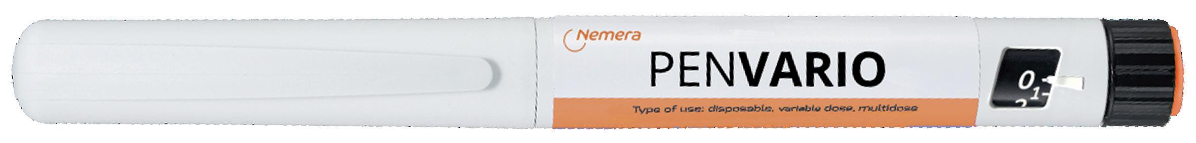
On the topic of clinical trials, an integrated connected pen is also available. Customised from Nemera’s reusable pen platform PENDURA AD, it features a Bluetooth module integrated into the pen itself, which can help transfer data to an app. Before transferring it, the data related to the injected dose are displayed on the screen, together with the date and time of injection. Complete data are available in the history on the application.
Nemera chose to develop a pen platform versatile enough to deliver the abovementioned drugs, as well as others. PENVARIO (Figure 4) is a manual pen platform able to address diabetes and obesity with rapid-acting or longacting insulins and GLP-1, osteoporosis with parathyroid hormones, such as abaloparatide, and fertility with folliclestimulating hormones, such as follitropin alpha. Each variant of the platform has been designed to match the specificities of the different target populations and regimens.
Returning to the example of India, where the prevalence of diabetes is very high, a multidose, disposable manual pen makes the treatment affordable at a low pricing point. It also offers the same patient injection experience as the conventional insulin pen injector.
Another area of interest is to help keep track of the number of doses injected. When the treatment becomes regular, patients have difficulty following up their regimen. In addition, within the ageing population, a lot of people take more than one treatment frequently, so having to remember
with a variable fixed dose disposable platform.
if they have taken their dose could be tricky. To avoid underdosing or overdosing, Nemera’s pen injectors can be customised with a specialised add-on. Designed to assist patients in monitoring their injections, it collects details on injected doses and adds them into a history. The aim is to accurately count the administered number of doses by recognising key parameters such as typical pen-use sequences, pen position and the distinctive injection-dose signature, while detecting each specific step of priming and injection.
Partnering with Nemera can simplify the process of integrating the selected pen injector with drug products, accelerating the development of combination products and expediting time to market while managing the complexities associated with managing the process. The company ensures that the selected pen injector is tailored to the specific needs of patient populations, drug characteristics and regulatory requirements. Its comprehensive services and capabilities cover critical areas

essential for the success of combination products, including:
• Analytical services and design verification
• Human factors and user experience management
• Instructional materials and packaging development
• Regulatory and quality strategy and submission authoring
• Drug/device assembly and packaging support.
The Insight by Nemera development and consulting organisation can support customers at any stage of development as a fully integrated or standalone partner. With locations in the US and Europe, Insight brings experience with a wealth of device types, patient populations and regulatory pathways. This broad experience and capabilities allows it to act as a partner and extension of customer teams delivering best-in-class solutions, ensuring no compromises are made when collaborating.
Willing to provide a fully automated industrial line to its partners, Nemera has invested in a new plant, offering its capability to produce prototypes and small series for clinical batches as well as large-scale automated volumes. Gathering state-of-the-art equipment from moulding to assembly and quality control testing, this new facility (Figure 5) includes an ISO 8 clean room and complies with the Building Research Establishment Environmental Assessment Method (BREEAM) recommendations. For instance, heat is recovered from the process line, and the facility also segregates and sorts all waste, aiming at recycling 100%.
Successful navigation of challenges often requires a partner with a broad set of capabilities and services. Nemera’s integrated device portfolio, development,
consulting and manufacturing services allow customers to achieve the outcome of a successful regulatory submission and commercial launch of safe, effective and differentiated combination products, with a single partner applying an agile process across the device and combination product value chain. Ultimately, the benefits of this approach will drive:
The needs of patients and clinical stakeholders are at the centre from the start of the programme to develop a custom patient engagement strategy that is consistently considered throughout the process to maximise effectiveness when launched into the market to drive loyalty from stakeholders.
Nemera understands that developers must navigate a complex ecosystem to achieve market success. Its services are aligned to help clients meet the expectations of key stakeholders, including healthcare professionals, networks, payers and regulators to ensure that their needs are met throughout the process.
The value of Nemera’s integrated services lies in the flexibility they offer, allowing customers to focus on their core business of drug discovery and development. Nemera offers best-in-class solutions for devices and combination products, ensuring that no compromises are made when collaborating with the organisation.
A single partner working across the journey limits transitions between suppliers and ensures consistent execution of strategy. Nemera also provides a wealth of options for developing and realising a device to accelerate time to registration and market from small-batch to large-scale
manufacturing and any interim supply required in between. When combined with the company’s service offering, this can significantly reduce timelines.
Looking to the future in this area, Nemera is just at the beginning of the journey because several pathologies are currently being studied to be treated with the same drug type. Some of them include obesity comorbidities in the cardiovascular field, which undoubtedly means treating more patients and extending the age range from paediatrics to elderly patients.
It goes without saying that sustainability is a priority in every aspect of Nemera’s daily work. The new facility is a good example but the company is also engaged in working towards eco-materials and eco-design, as well as energy sourcing and consumption, and has committed to several targets set by standard organisations such as the Science Based Targets initiative.5
As a world-leading drug delivery device solutions provider, Nemera’s purpose of putting patients first enables it to design and manufacture devices that maximise
treatment efficacy. It is a holistic partner and helps its customers succeed in the sprint to market with their combination products. From early device strategy to state-of-theart manufacturing, Nemera is committed to the highest quality standards. Agile and open-minded, the company works with its customers as colleagues to go the extra mile to fulfil their mission.
1. “Obesity and overweight”. WHO, Mar 1, 2024.
2. “One in eight people are now living with obesity”. Press Release, WHO, Mar 1, 2024.
3. “WHO acceleration plan to stop obesity”. WHO, Jul 3, 2023.
4. NCD-RisC, “Worldwide trends in underweight and obesity from 1990 to 2022: a pooled analysis of 3663 population-representative studies with 222 million children, adolescents, and adults”. The Lancet, 2024, Vol 403 (10431), pp 1027–1050.
5. “Ambitious corporate climate action”. Web Page, Science Based Targets, accessed May 2024.
Cécile Gross is Marketing Global Category Manager at Nemera, focusing on parenteral devices. She oversees the product portfolio strategy, development and lifecycle for safety system, pen injector and on-body injector platforms. Ms Gross has more than two decades of experience in the medical device industry, marketing business-to-business technological products and implementing product lifecycle management for various kinds of devices. A graduate in International Business, she completed her initial training with a master’s degree in Marketing and Management in the Healthcare Industry at the IMIS Institute (Lyon, France).
Mark Tunkel is Global Category Director, Services, at Nemera. He was previously a partner at Insight Product Development, which was acquired by Nemera in 2019 and became the Insight Innovation Center. With more than 20 years of global business development experience and a deep understanding of the marketplace challenges and trends impacting the pharma industry, Mr Tunkel has advised many of the world’s leading companies on their product development and innovation strategies, with an emphasis on driving realisation and the most favourable business outcomes.
Our solutions for diabesity, one pen at a time
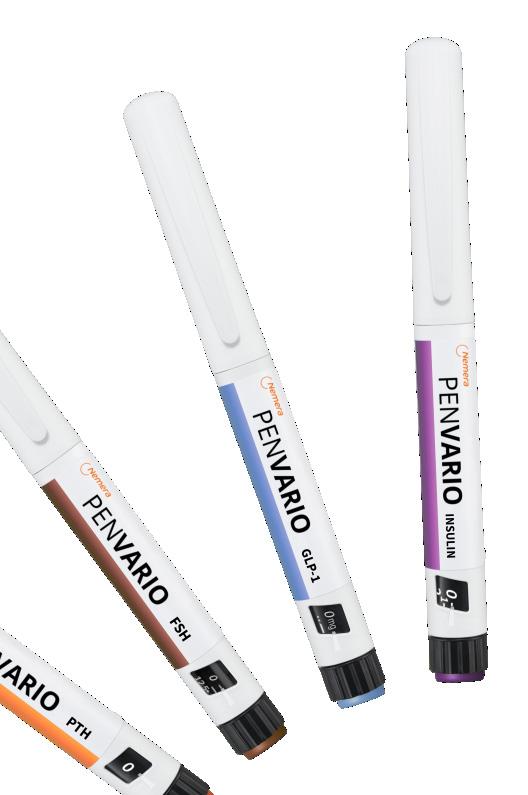
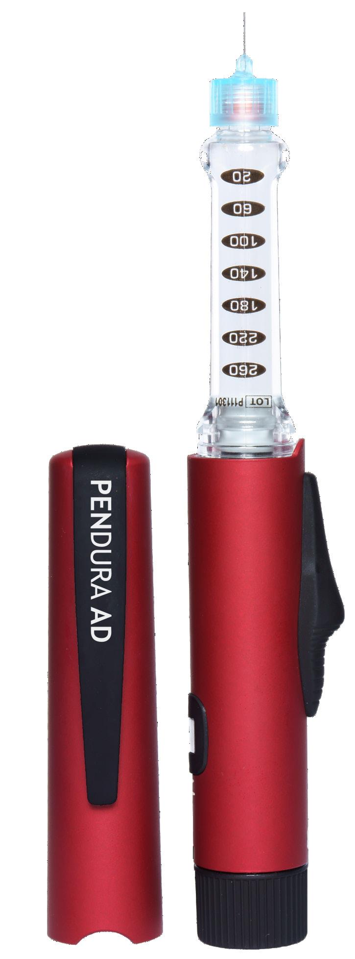
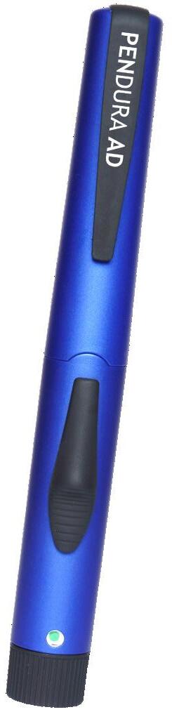

In this article, Manuela Giacon, Product Manager, Pen Injectors, and Josh Gordon, Product Manager, Auto-Injectors, both at Stevanato Group, review the growth in demand for glucagon-like peptide-1 treatments and present the company’s response to this exciting opportunity, showcasing its Alina® device platform for pen injectors and the Aidaptus® two-step, single-use autoinjector.
It is estimated that the glucagon-like peptide-1 (GLP-1) market will exceed US$100 billion (£80.3 billion) by 2030, driven equally by diabetes and obesity usage. In the US alone, the total number of GLP-1 users may be as high as 30 million by 2030 – that is around 9% of the overall population.1
Stevanato Group believes that, for the foreseeable future, autoinjectors and pen injectors will remain at the forefront of GLP-1 delivery. While this potential blockbuster treatment presents considerable opportunities for pharma partners, there are, of course, challenges, specifically in terms of satisfying demand.
In 1986, 10 years after it was first introduced by Smith Kline & French, sales of peptic ulcer treatment Tagamet (cimetidine) surpassed the $1 billion mark, making it the first drug in history to be classified as a blockbuster.2
“The
pharmaceutical industry has welcomed a host of therapies and vaccines into this revered club, with indications covering everything from cancer and covid-19 to arthritis and atrial fibrillation.”
Since then, the pharmaceutical industry has welcomed a host of therapies and vaccines into this revered club, with indications covering everything from cancer and covid-19 to arthritis and atrial fibrillation. In recent times, however, much of the attention in the blockbuster category has been focused on GLP-1 receptor agonists (GLP-1 agonists). These drugs were originally developed for the management of blood sugar levels in people with Type 2 diabetes but have recently experienced a dramatic boom in demand as treatments for obesity.
A high-profile case in point is semaglutide. The drug was approved by the US FDA in June 2021 as a 2.4 mg once-weekly injection for chronic weight management in adults with obesity or those overweight with at least one weight-related condition, such as high blood pressure, Type 2 diabetes or high cholesterol.3 In 2023, according to market information from Midas (IQVIA), sales of semaglutide for weight management more than quadrupled year-on-year, and further interest has been spurred by new indications related to reducing cardiovascular risk, and emerging benefits are being shown in people with Alzheimer’s disease.4,5
The strength of these figures clearly demonstrates the intense demand for GLP-1 treatments, but it does not convey the unforeseen implications of such high levels of popularity. This issue came to the fore in early 2024 when the MHRA issued

Manuela Giacon
Product Manager, Pen Injectors E: manuela.giacon@stevanatogroup.com

Josh Gordon Product Manager, Auto-Injectors E: josh.gordon@stevanatogroup.com
Stevanato Group SpA Via Molinella 17 35017 Piombino Dese Padova Italy
www.stevanatogroup.com
a National Patient Safety Alert triggered by global supply issues for certain GLP-1 drugs, advising healthcare professionals to conserve existing stock for patients with Type 2 diabetes.6,7 The implementation of such measures ensures that the critical priority of patient needs continues to be met, while also avoiding patients seeking what the WHO describes as “falsified or substandard” versions of these medicines through unregulated outlets on the internet.8
Looking to the future, demand for GLP-1 drugs is expected to remain high as healthcare systems look to manage obesity and diabetes among an ageing population. By 2026, anti-diabetics are expected to attract the third highest level of spending after oncology and immunology treatments. And with more than half of the global population (51% or over 4 billion people) predicted to be either overweight or living with obesity by 2035, investment in obesity drugs is forecast to rise by a compound annual growth rate of 35%–38% between 2023 and 2027.9,10
While some GLP-1 treatments currently in the pipeline are set to reach the market in oral tablet form, autoinjectors and pen injectors currently at the forefront of GLP-1 delivery will continue to deliver multiple patient benefits across this significantly expanded market segment.
For pharma companies aiming to satisfy this surging demand, the choice of delivery mechanism and delivery partner will have implications for supply chain capacity and resilience. Expediting such a device to market requires assessment and resolution of risk in areas such as drug containment and device specification as well as scaled-up production, assembly, fill-finish and distribution. Access to proven technologies, relevant device options, global manufacturing expertise and go-to-market knowledge are, therefore, all integral to supporting drug companies’ commercial strategies with a time-efficient and costeffective route to market.
Stevanato Group combines global manufacturing reach with an extensive product portfolio, allowing the company to support pharmaceutical partners with an end-to-end approach at scale. For applications suited to pen injectors, Stevanato Group’s Alina® device platform offers partners a customisable approach to the delivery of variable and multidose treatments (Figure 1). The pen injector’s performance, features and intuitive handling are compatible with established
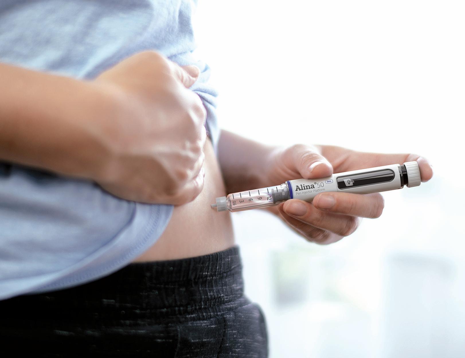
therapeutic regimens as well as innovator drug therapies that require a multidose delivery device for conditions such as diabetes and weight management. Alina® has been designed with patient convenience and confidence in mind. It features an ergonomic form and intuitive delivery mechanism, with patients receiving visual and audible feedback for clear confirmation of dose setting, correction, and injection.
From a manufacturing perspective, Alina® devices are built around the concept of flexibility. Production is handled at Stevanato Group’s FDA-inspected facility in Germany, providing customers with access to dedicated, established tooling and sub-assembly lines that can accommodate levels of customisation according to a customer’s production requirements. This
ensures devices comply with the stringent quality standards demanded by regulatory authorities while avoiding the requirement to engage in a highly bespoke device design, prototyping and testing development process, along with the establishment of tailored tooling and assembly lines. As such, the Alina® platform provides a cost-effective and time-efficient pathway to take GLP-1 pen injector devices from bench to large-scale production, factoring in changing volume demands as a product scales throughout its development lifecycle.
In the autoinjector segment, Stevanato Group’s collaboration with Owen Mumford Pharmaceutical Services (OMPS) (Oxford, UK) opens the door to next-generation single-use applications via the Aidaptus® device platform (Figure 2). Intended to
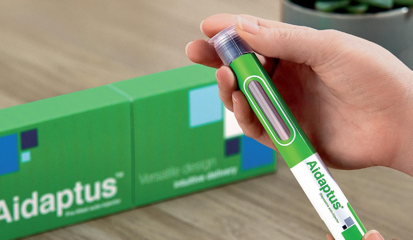
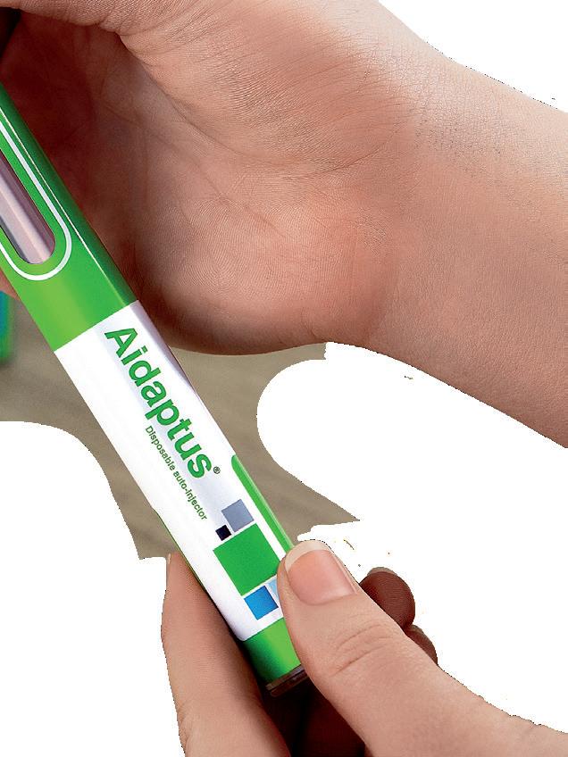
balance innovation and familiarity, Aidaptus® is a two-step, single-use autoinjector with a versatile hybrid design that can accommodate both a 1 and 2.25 mL prefilled syringe in the same form factor. The platform’s novel plunger rod technology facilitates flexible filling with no change of parts, allowing for a single device to accommodate multiple dose configurations, consolidating SKUs (stock keeping units).
Patients using Aidaptus® benefit from a familiar, intuitive delivery mechanism, while compatibility with Stevanato Group’s 29G special thin-wall needle allows for a reduction in the time and force required to inject viscous solutions. The benefits of this novel component, which are accentuated in applications involving large-molecule biologics, can be seen in an improvement in the overall patient experience when delivering GLP-1 therapies. This is achieved by expanding the internal diameter of the needle while maintaining the same external dimensions as a standard thinwalled needle, ensuring compliance with the ISO 9626:2026 requirements for the manufacture of hypodermic needles and medical devices.
With Aidaptus®, Stevanato Group’s understanding of the critical area of drug containment is brought to the fore through compatibility of the platform with Nexa® prefilled glass syringes. Supplied pre-sterilised, Nexa® high-performance syringes have been developed to ensure compatibility with drug delivery devices to meet the growing demand for drug products that patients can self-administer from the comfort of their own homes. Together, these innovative packaging solutions offer unrivalled quality and reliability for even the most sensitive and complex drug formulations.
For drug owners and manufacturers, the Aidaptus® plunger rod’s ability to automatically self-adjust to the drug fill volume during final assembly, without requiring any part changes or associated process steps, streamlines the final assembly operation. Additionally, the device’s inherent flexibility supports various dose configurations earlier in the clinical development process (e.g. dose-finding studies) and commercial ambitions as
BRINGING YOU...
“Stevanato Group can offer in-house expertise in the design and delivery of highly efficient and flexible assembly production lines, which can deliver time and cost savings for pharma partners in various scenarios.”
part of a lifecycle management programme, both of which help to accelerate time to market.
In the case of both Aidaptus® and Alina®, individual device capabilities are married to the breadth of Stevanato Group’s service portfolio and comprehensive product knowledge in drug delivery. This unified, single-point-of-contact approach brings significant production benefits to pharma partners through minimising the number of friction points that can be present in a more fragmented supply chain and ensuring that all components ultimately knit together into a coherent combination product. This is evident with Alina®, which, while optimised for Stevanato Group’s range of Nexa® glass cartridges, is fully compatible with ISO 3 mL glass cartridges and can be integrated into a variety of fillfinish systems. Likewise, the Aidaptus® platform is compatible with all equipment suppliers with the associated format parts, allowing final assembly of the device to be integrated into existing CDMO manufacturing structures.
Where required, however, Stevanato Group can offer in-house expertise in the design and delivery of highly efficient and flexible assembly production lines, which can deliver time and cost savings for pharma partners in various scenarios, including where final assembly must be completed at a customer site or at their CDMO. Here, Stevanato Group’s in-house capabilities allow for device production equipment to be entirely designed, developed, fabricated and commissioned by the company’s own engineers, limiting the complexity and risks that can arise when engaging with multiple third parties. Additionally, the core and consistent assembly technology that spans from the company’s smaller benchtop assembly unit to its higher commercial assembly platform
facilitates efficient industrialisation scale-up, which is advantageous for existing and new entrants in the GLP-1 space.
Looking to the future, Stevanato Group also offers pharma companies long-term support for drug delivery devices through its investment plan to further strengthen the company’s supply offering in multicavity tooling, injection moulding and sub-assembly offerings at its locations worldwide. Furthermore, Stevanato Group’s relationship with OMPS is an example of how partnerships and collaboration can add further layers of market-leading expertise to the company’s offering.
While such investments cement Stevanato Group’s commitment to deliver complex products at a truly global scale, its underlying objective is to reduce the number of engagement points across the combination product value chain to help pharma partners meet the sizeable and sustained demand for GLP-1 products. In a more fragile world, where geopolitical instability has the potential to cause knock-on effects for commercial activities, Stevanato Group’s highly integrated service offering and global reach can provide greater control and introduce higher levels of efficiency and continuity of supply throughout the supply chain, from sourcing raw materials through to the robust production of patient-friendly autoinjectors and pen injectors that are fully compliant with current regulatory requirements.
Founded in 1949, Stevanato Group is a leading global provider of drug containment, drug delivery and diagnostic solutions to the pharmaceutical, biotechnology and life sciences industries. Stevanato Group delivers an integrated, end-to-end portfolio of products, processes and services that
addresses customer needs across the entire drug lifecycle at each of the development, clinical and commercial stages. Stevanato Group’s core capabilities in scientific research and development, its commitment to technical innovation and its engineering excellence are central to its ability to offer value-added solutions to clients.
1. “The increase in appetite for obesity drugs”. J.P. Morgan, Nov 9, 2023.
2. “Tagamet: The Discovery of Histamine H2-receptor Antagonists”. ACS, accessed Apr 2024.
3. “FDA Approves New Drug Treatment for Chronic Weight Management, First Since 2014”. US FDA, Jun 4, 2021.
4. Hopkins Tanne J, “Wegovy: FDA approves weight loss drug to cut cardiovascular risk”. BMJ, 2024, Vol 384, article: q642.
5. “Novo Nordisk”. Alzheimer’s Disease International, Web Page, accessed Apr 2024.

6. National Patient Safety Alert. UK NHS, Jan 3, 2024.
7. Shortage FAQs. Diabetes UK, Mar 20, 2024.
8. “Shortages impacting access to glucagon-like peptide 1 receptor agonist products; increasing the
potential for falsified versions”. World Health Organization, Jan 29, 2024.
9. World Obesity Atlas 2023. World Obesity, accessed Apr 2024.
10. “The Global Use of Medicines 2023 Outlook to 2027”. IQVIA, Jan 18, 2023.
Manuela Giacon is Product Manager, Pen Injectors at Stevanato Group. She brings over a decade of expertise in the parenteral primary packaging and medtech sectors. Ms Giacon conducts thorough analyses of new markets, growth areas, current trends, various customer segments, potential partnerships and services. Through close collaboration with development teams, she guarantees finely tuned bespoke solutions to meet customer demands within the ever-evolving market environment. Ms Giacon holds a degree in Economics and, before her current role, she was part of the Strategic Marketing and Communication department.
Josh Gordon is currently Product Manager, Drug Delivery Systems at Stevanato Group, focusing on autoinjectors. With a bachelor’s degree in Biomedical Engineering from the University of Cincinnati (OH, US), and a current MBA student at Xavier University (OH, US), Mr Gordon has broad experience in customer-facing, upstream marketing and engineering roles in combination products and clinical research, including product management, business development and alliance management.

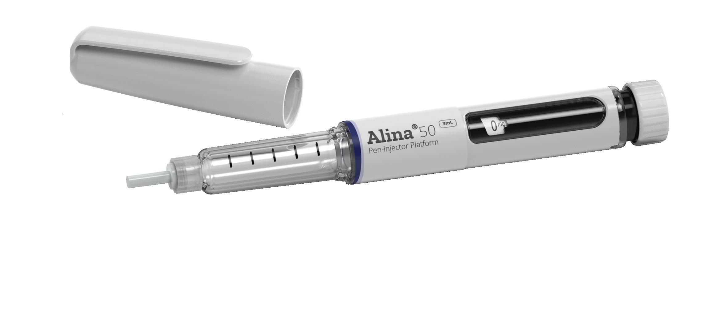
At Stevanato Group we combine global manufacturing reach with an extensive product portfolio, allowing us to support pharmaceutical partners with an end-toend approach at scale. For applications suited to pen injectors, Stevanato Group’s Alina ® device platform offers partners a customisable approach to the delivery of
variable and multi-dose treatments
In the auto-injector segment, our partnership with Owen Mumford Pharmaceutical Services opens the door to next-generation singleuse applications via the Aidaptus ® device platform , accommodating both a 1ml and 2.25ml prefilled syringe in the same form factor while allowing flexible filling with no change parts.

In this article, Lars Berger, Senior Manager, and Eric Linvill, PhD, Senior CAE Engineer, both at SHL Medical, discuss the rapid growth of the cardiometabolic disease space in light of the global obesity epidemic and how advanced autoinjector and injection pen technologies, such as SHL’s Molly platform, will be necessary to meet the challenges presented by this disease area.
The rapid growth of glucagon-like peptide-1 receptor agonists (GLP-1RA) for the treatment of obesity has drawn public attention to treatments for cardiometabolic diseases. With an already significant demand for such treatments that is expected to grow further, the interest in new drug development in this area is increasing. Most of these medications require injectable formats, creating a need for user-friendly autoinjector devices that are readily available to the pharmaceutical industry on a large and unprecedented scale.
The pervasiveness of obesity continues to be staggering. According to the latest available data published in The Lancet, more than a billion people worldwide are living with obesity. In the US alone, the 2022 adult prevalence rate for obesity ranged from 37.7–47.7%. Global estimates
“Now
recognised as an epidemic, there is increasing pressure on hospitals and clinics, as the centre of care, to treat obesity and other related diseases medically.”
for the year 2035 show that no apparent reversal of the trend is coming, with 1.9 billion people expected to be affected. Now recognised as an epidemic – referred to as “globesity” by the WHO – there is increasing pressure on hospitals and clinics, as the centre of care, to treat obesity and other related diseases medically.1–4
In addressing this global epidemic, it is important to acknowledge the relationship between obesity and other cardiometabolic diseases. For this, one is reminded of the strong link between obesity and metabolic syndrome (MetS). In the words of the American Heart Association and the National Heart, Lung, and Blood Institute, MetS is a “constellation of interrelated risk factors of metabolic origin”. Such cardiometabolic risk factors, the most widely recognised of which include dyslipidaemia, hypertension and elevated plasma glucose, have been shown to promote the development of atherosclerotic cardiovascular disease (ASCVD). At the same time, MetS has been reported to increase the risk of Type 2 diabetes (T2D).5–8
The clear links between MetS, its underlying risk factors and resultant diseases such as ASCVD and T2D open many pathways to treating such cardiometabolic conditions clinically, together or individually. As such, it becomes increasingly clear that treatment delivery must go beyond the contemporary focus on obesity and recognise the network of interrelated cardiometabolic diseases that lie in front.

Lars Berger Senior Manager E: lars.berger@shl-medical.com

Dr Eric Linvill Senior CAE Engineer E: veric.linvill@shl-medical.com
SHL Medical AG Gubelstrasse 22 6302 Zug Switzerland
www.shl-medical.com
Fixed-dose combinations
compound
Table 1: A non-exhaustive list of GLP1-RAs that have been approved to treat T2D. Elimination half-lives were adapted from a 2021 review paper by Nauck et al. The list does not include compounds that are still in development or where available information is scarce, such as efpeglenatide, beinaglutide and PEG-loxenatide. Exenatide was also launched as a once-weekly autoinjector in 2018, marketed as BYDUREON® BCise™ (AstraZeneca).9,10,11
As preventative care has shown little success in halting the rise in cardiometabolic diseases, new medicines will be crucial for improving the quality of life and independence of as many patients as possible. As research and development in GLP1-RAs and other cardiometabolic treatments continues to evolve, so too does the opportunity to enable at-home patient care with pen injectors and autoinjectors. At-home drug delivery opens pathways to unburden primary care services and enables treatment strategies in safe and easy-touse self-injection formats. For pharma and biotech companies with cardiometabolic compounds in the pipeline, selecting the right device partner is critical to ensuring a successful launch and continued success.
Progress in the science of GLP1-RAs has come a long way (Table 1). Since
the isolation of glucose-dependent insulinotropic polypeptide (GIP) in the 1970s, further progress has been made in incretin biology, leading to the discovery of the physiological actions of GLP-1 receptor agonists. However, it was only in 2012 –roughly a decade ago – that once-weekly GLP-1RAs were launched. This started with the launch of the long-acting/extended release exenatide microspheres, followed by dulaglutide and albiglutide in 2014.10 Interestingly, perhaps the most successful of this wave of once-weekly products, dulaglutide, was launched in a three-step autoinjector, which compared favourably with formulations that required more complicated preparation steps for the user. Not long after, the therapeutic impact of GLP1-RAs expanded from diabetes to chronic weight management for adults with obesity. Key compounds that come to mind are semaglutide, marketed as Wegovy® by Novo Nordisk, and Eli Lilly’s tirzepatide, marketed as Zepbound®. The further enhanced effects of these second-generation compounds on
lowering blood glucose, reducing weight, and protecting the heart and kidneys, is now encouraging further clinical development and points to many possible novel combinations of medicines in the future.
TREATMENT OF CARDIOMETABOLIC DISEASES ASKS FOR SPECIFICALLY DESIGNED DELIVERY DEVICES
Today, there are more than two dozen therapeutic candidates in the GLP-1 drug class undergoing clinical research. Depending on the API and the formulation, these drugs require a variety of delivery devices, ranging from multi-dose pen injectors to syringe- and cartridge-based autoinjectors. Additionally, these treatments are being developed for conditions such as obesity, diabetes and metabolic dysfunctionassociated steatohepatitis (MASH), where patients may potentially require the simultaneous use of multiple medications. Each medication, in turn, requires a specific delivery device technology.12
“Since
2015, SHL has supported the launch of six combination products indicated for cardiometabolic diseases, including incretin mimetics for T2D and obesity in particular, as well as PCSK9 inhibitors for hyperlipidaemia.”
Reflecting on the success of alreadymarketed devices, it is evident that future cardiometabolic treatments will rely in large part on proven drug delivery technologies, like two-step single-use autoinjectors. Whether for novel compounds or generics, such molecules will require user-friendly self-injection solutions developed by a device partner with proven expertise in producing devices for this emerging disease area.
With more than 30 years of industry experience in total – resulting in more than 50 combination products – the last ten years has seen SHL tackling a plethora of device projects in collaboration with pharma companies, particularly in the cardiometabolic disease area. Since 2015, SHL has supported the launch of six combination products indicated for cardiometabolic diseases, including incretin mimetics for T2D and obesity in particular, as well as PCSK9 inhibitors for hyperlipidaemia.
In so doing, SHL delivered at least 49.5 million devices into the hands of patients living with cardiometabolic diseases in 2023 alone, a number unrivaled in the field of proprietary autoinjector technology. Further analysis of IQVIA data suggests that SHL’s devices have supported the treatment journey of at least 1.6 million patients in this therapeutic area (Figure 1).
Many of these combination product launches relied on SHL’s modular Molly platform autoinjectors (Figure 2). In drugdevice projects within the cardiometabolic area, the demand is often high. Pharma and biotech companies need partners with proven device technologies supported by a
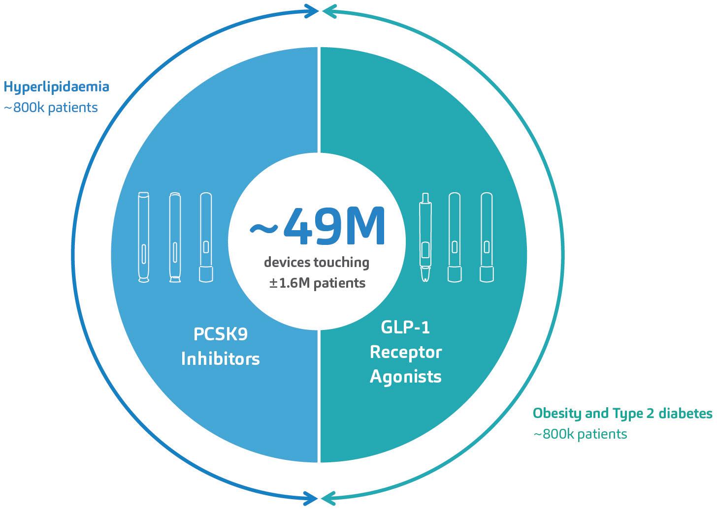
Figure 1: SHL’s devices have supported the launch of six combination products for the treatment of cardiometabolic diseases within the last 10 years. An analysis of market data by IQVIA indicates that SHL’s devices have touched at least 1.6 million patients afflicted with hyperlipidaemia, T2D or obesity. These numbers do not include emergency combination product treatments for severe hypoglycaemia.
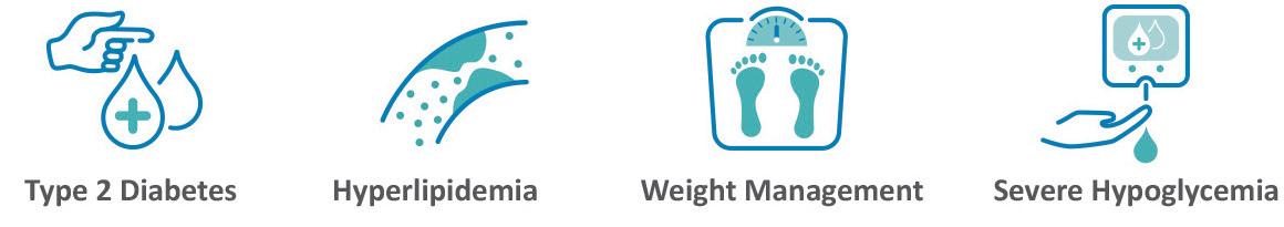
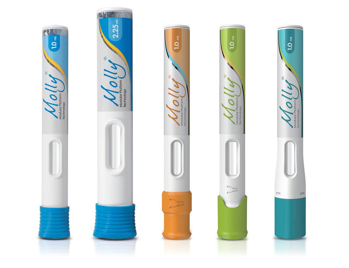
2: Built upon proven experience in the cardiometabolic space, SHL’s modular Molly platform autoinjectors are well positioned to address the up-and-coming developments in this therapy area.
globally dispersed infrastructure capable of scaling manufacturing. They also need to ensure high satisfaction rates for end users.
SHL’s Molly autoinjector has consistently
met this challenge – the modular platform has been integral to the second-generation GLP1-RAs approved for T2D (in Japan in 2020) and obesity (in the US in 2021).13,14
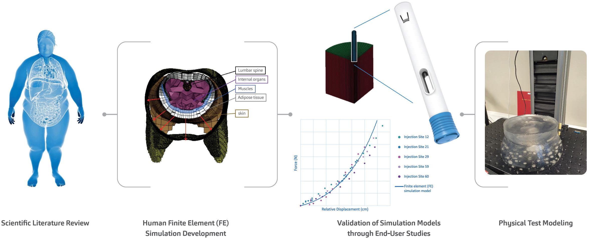
Figure 3: As part of SHL’s efforts to advance the understanding of autoinjector activation even in the softest injection sites, SHL’s research team presented the proceedings of a study at the 2023 Parenteral Drug Association (PDA) Universe of Pre-Filled Syringes and Injection Devices Conference.20
The Molly platform has also proven itself in the lifecycle management of product families. In 2015, one of SHL’s pharma partners decided to perform lifecycle management on its PCSK9 autoinjectors for hyperlipidaemia. The project required two dosing formats in autoinjectors bearing communal industrial design and branding elements set by the pharma partner. A published usability study on the nowmarketed high-dose, 2.0 mL format reported “no new product technical issues or no new safety concerns” compared with the 1.0 mL autoinjector format marketed previously. Study results like this affirm SHL’s original findings on the Molly device’s ease of use and highlight the platform device’s applicability in metabolic therapy areas.15
Today, the metabolic space is experiencing extraordinary growth, with emerging clinical progress in mono-, dual- or triple-receptor agonists for obesity. The Molly autoinjector is well positioned to address emerging candidate compounds in this burgeoning market, offering quickto-clinic device development options to support a pharma company’s clinical trial strategy.16
As SHL continues to collaborate with global pharma companies across various treatment areas, its commitment to providing the best possible experience for end users of its autoinjector technologies remains steadfast. As pioneers in self-
“With the obesity epidemic and the rising prevalence of cardiometabolic diseases, understanding adipose tissue function and distribution becomes critical.”
injection technology, one of SHL’s aims is to deepen its understanding of how autoinjectors activate, even in the softest injection sites.
Various studies have shown that body mass index (BMI) does not sufficiently reflect adipose tissue distribution, which includes visceral fat. With the obesity epidemic and the rising prevalence of cardiometabolic diseases, understanding adipose tissue function and distribution becomes critical. This is increasingly relevant for disease areas such as obesity and cardiometabolic diseases, where metabolic phenotypes could differ from other patient populations.17–19
To address this, the SHL research team conducted a series of soft tissue user (in vivo) studies, simulation (in silico) studies and physical test (in vitro) studies, providing a mechanistic view of the interactions between the autoinjector and human soft tissue during injection activation (Figure 3). The development of these in silico and in vitro models, which themselves
represent challenging cases from the in vivo studies, goes above and beyond what is required in standard autoinjector testing methodologies, affirming SHL’s commitment to end users. This study on autoinjector activation performance also confirms the safety and reliability of SHL’s autoinjector technologies, even in more complex or heterogeneous patient groups.
SOLUTIONS
The present obesity epidemic, affecting more than a billion people, underscores the urgency of addressing the various branching healthcare challenges related to cardiometabolic diseases. SHL Medical, a leader in self-injection solutions, is dedicated to improving lives with its autoinjector technologies. With a proven track record of meeting the growing needs of the cardiometabolic market, SHL’s Molly autoinjectors are poised to usher in a new era in cardiometabolic care. SHL is committed to responding with innovative solutions to meet emerging needs for specialised device technologies in future drug discoveries.
SHL Medical is a solutions provider in the design, development and manufacturing of advanced drug delivery devices, such as autoinjectors and pen injectors. The company also provides final assembly,
labelling and packaging services for leading pharmaceutical and biotech companies across the globe. With locations in Switzerland, Taiwan, Sweden and the US, SHL Medical has successfully built a strong international team of experts that develops breakthrough drug delivery solutions for pharma and biotech customers. These include advanced reusable and disposable injection systems that can accommodate large-volume and high viscosity formulations – and connected device technologies for next-generation healthcare.
1. “Worldwide trends in underweight and obesity from 1990 to 2022: a pooled analysis of 3663 populationrepresentative studies with 222 million children, adolescents, and adults”. Lancet, 2024, Vol 403(10431), pp 1027–1050.
2. “Body-Mass Index – Evolution of BMI over time”. Web Page, NCD RisC, accessed May 2024.
3. “World Obesity Atlas 2023”. World Obesity Federation, Mar 2023.
4. “Controlling the global obesity epidemic”. Web Page, WHO, accessed May 2024.
5. Grundy SM et al, “Diagnosis and Management of the Metabolic Syndrome”. Circulation, 2005, Vol 112(17), pp 2735–2752.
6. Lusis AJ, Attie AD, Reue K, “Metabolic syndrome: from epidemiology to systems biology”. Nat Rev Genet, 2008, Vol 9(11), pp 813–830.
7. Cornier M-A et al, “The metabolic syndrome”. Endocr Rev, 2008, Vol 29(7), pp 777–822.
8. Fahed G et al, “Metabolic Syndrome: Updates on Pathophysiology and Management in 2021”. Int J Mol Sci, 2022, Vol 23(2), Article 786.
9. Nauck MA “GLP-1 receptor agonists in the treatment of type 2 diabetesstate-of-the-art”. Mol Metab, 2021, Vol 46, Article 101102.
10. Andersen A et al, “Glucagon-like
peptide 1 in health and disease”. Nat Rev Endocrinol, 2018, Vol 14(7), pp 390–403.
11. Wang J-Y et al, “GLP−1 receptor agonists for the treatment of obesity: Role as a promising approach”. Fron Endocrinol (Lausanne), 2023, Vol 14, Article 1085799.
12: Internal analysis of trials involving GLP-1 RA and GLP-1 RA combinations in Phases II and III registered on clinicaltrials.gov. SHL, February 2024.
13. “2型糖尿病治療剤 持続性GLP-1 受容体作動薬/セマグルチド(遺 伝子組換え)オゼンピック® 皮下 注 0.25mg SD、0.5mg SD、1.0mg SD – 新発売のご案内” (Type 2 diabetes treatment agent Long-acting GLP-1 receptor agonist/semaglutide (genetical recombination) Ozempic® subcutaneous injection 0.25mg SD, 0.5mg SD, 1.0mg SD – New release information). Japanese Press Release, Novo Nordisk, Jun 2020.
14. “FDA Approves New Drug Treatment for Chronic Weight Management, First Since 2014”. Press Release, US FDA, Jun 2021.
15. Frias JP et al, “The SYDNEY Device Study: A Multicenter, Randomized, Open-label Usability
Study of a 2-mL Alirocumab Autoinjector Device”. Clin Ther, 2020, Vol 42(1) pp 94–105.
16. Jastreboff AM, Kushner RF, “New Frontiers in Obesity Treatment: GLP-1 and Nascent Nutrient-Stimulated Hormone-Based Therapeutics”. Annu Rev Med, 2023, Vol 74, pp 125–139.
17. Mittal B, “Subcutaneous adipose tissue & visceral adipose tissue”. Indian J Med Res, 2019, Vol 149(5), pp 771–573.
18. Goossens GH, “The Metabolic Phenotype in Obesity: Fat Mass, Body Fat Distribution, and Adipose Tissue Function”. Obes Facts, 2017, Vol 10(3), pp 207–215.
19. Shuster A et al, “The clinical importance of visceral adiposity: a critical review of methods for visceral adipose tissue analysis”. Br J Radiol, 2012, Vol 85(1009), pp 1–10.
20. Linvill E et al, “Rethinking human factors in obesity: Development of simulation and physical test models of human soft tissue to study autoinjector activation performance”. Poster Presentation, PDA Universe of Pre-Filled Syringes and Injection Devices, Gothenburg, 2023.
Lars Berger is an accomplished professional with over 30 years of international experience driving innovation and growth in the medical device and healthcare industries. As Senior Manager of Portfolio Strategy and Customer Solutions at SHL Medical, he focuses on building and optimising the product portfolio by identifying opportunities based on customer needs, technical limitations and regulatory requirements. He has previously led over 15 development projects for pharma companies including Johnson & Johnson and Sanofi, including pioneering advancements in diagnostics, drug delivery devices, disease management applications and software as medical devices. He holds a master’s degree in Business Science from the University of Regensburg (Germany).
Eric Linvill received his PhD in Solid Mechanics from the KTH Royal Institute of Technology (Stockholm, Sweden) in 2017 and is currently a Senior CAE Engineer at SHL Medical. Dr Linvill has research and professional experience in understanding and modelling the mechanical behaviour of biological and synthetic polymers and the development of advanced, non-linear finite element (FE) simulation models.

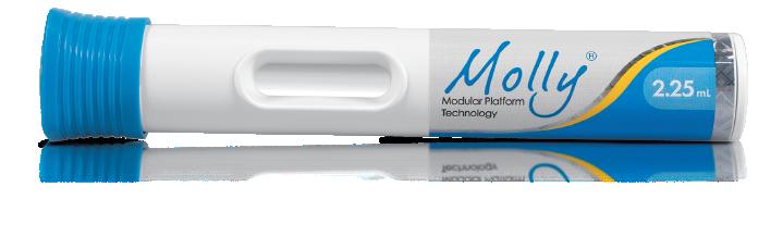
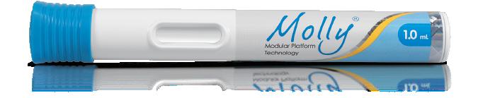
In this article, Alex Vasiev, PhD, Principal Biomedical Engineer at Springboard, discusses the challenges inherent in understanding flow rates in injectable drug delivery when dealing with non-Newtonian fluids, and provides an overview of how to calculate flow rates for power law, Carreau and Cross fluids.
The pharmaceutical industry is currently undergoing a period of rapid innovation, propelled by several factors. These include advancements in the development of biologics, which are becoming increasingly diverse,1 decentralised healthcare practices and a shift towards administering injections less frequently in at-home settings.2 Additionally, small molecules are being designed using artificial intelligence (AI) drug discovery techniques.3 While these therapeutic innovations hold promise, they can also bring forth unforeseen challenges in drug formulationand delivery.
These challenges can include ensuring the stability of large or fragile biologics at higher therapeutic concentrations or improving the solubility of poorly soluble APIs. Overcoming these hurdles can require the implementation of sophisticated solutions, such as microcarriers, adjuvants, excipients and stabilising matrices.4 It is crucial to recognise that these formulations profoundly impact the physical properties of drugs and can present challenges for parenteral drug delivery, especially in rapid, automated systems such as autoinjectors.
One example of this is highconcentration monoclonal antibodies, which can experience aggregation under agitation-induced stress. Stabilising matrices composed of polymer, lipid crystal or polysaccharide gels can offer improved stability and efficacy but can exhibit nonNewtonian flow behaviour. This is also true for long-acting injections composed of particulate suspensions where particle particle interactions and alignment can result in the same.
The modelling of syringeability and delivery of parenteral formulations has often focused on Newtonian models and the Hagen-Poiseuille equation. While this generally performs well, it is not suitable for predicting the behaviour of non-Newtonian fluids. This is because non-Newtonian fluids
“The
modelling of syringeability and delivery of parenteral formulations has often focused on Newtonian models and the HagenPoiseuille equation. While this generally performs well, it is not suitable for predicting the behaviour of non-Newtonian fluids.”
do not uniformly thicken or thin as they pass through a needle; rather, this effect occurs near the needle wall where the fluid experiences the highest shear.
For shear-thinning fluids, this phenomenon results in plug-like flow, which can be seen in the dispensation of fluids such as toothpaste. This results in a very different volumetric flow rate at a given pressure. In autoinjectors, this issue is further complicated by the decay of delivery force over the stroke, which is characteristic of most devices powered by springs or gas.
To tackle this challenge, this article presents an overview of solutions to non-Newtonian fluids described by the power law, Cross and Carreau models. The aim is to provide a toolbox to assist the integration of formulation development and device design. Specifically, it examines model solutions in the context of an autoinjector where the delivery force varies throughout the delivery process. Adopting a standardised approach to predictive modelling can enable the industry to make well-informed decisions early on and provide valuable insights into potential device parameters during formulation development.

Dr Alex Vasiev
Principal Biomedical Engineer E: alex.vasiev@springboard.pro
Springboard Pro Ltd,
a Sanner Group Company
St John’s Innovation Centre Cowley Road Cambridge CB4 0WS
United Kingdom www.springboard.pro
Container
• Volume (V)
• Diameter (D)
TITLE:
TITLE:
TITLE:
TITLE:
• Diameter (d)
• Length (l)
THROUGH THICK AND THIN: MODELLING THE DELIVERY OF NONNEWTONIAN FORMULATIONS
THROUGH THICK AND THIN: MODELLING THE DELIVERY OF NONNEWTONIAN FORMULATIONS
THROUGH THICK AND THIN: MODELLING THE DELIVERY OF NONNEWTONIAN FORMULATIONS
THROUGH THICK AND THIN: MODELLING THE DELIVERY OF NONNEWTONIAN FORMULATIONS ## CONTACT BOX:
CONTACT BOX:
CONTACT BOX:
CONTACT BOX:
Spring
• Spring starting force (F0)
• Extension (x)
• Spring rate (k)
[author photo]
[author photo]
[author photo]
[author photo]
do not uniformly thicken or thin as they pass through a needle; rather, this effect occurs near the needle wall where the fluid experiences the highest shear.
do not uniformly thicken or thin as they pass through a needle; rather, this effect occurs near the needle wall where the fluid experiences the highest shear.
Dr Alex Vasiev
Dr Alex Vasiev
Dr Alex Vasiev
Plunger stopper
Dr Alex Vasiev
Principal Engineer
Principal Engineer
Principal Engineer
For shear-thinning fluids, this phenomenon results in plug-like flow, which can be seen in the dispensation of fluids such as toothpaste. This results in a very different volumetric flowrate at a given pressure. In autoinjectors, this issue is further complicated by the decay of delivery force over the stroke, which is characteristic of most devices powered by springs or gas.
• Stroke (L)
Principal Engineer
For shear-thinning fluids, this phenomenon results in plug-like flow, which can be seen in the dispensation of fluids such as toothpaste. This results in a very different volumetric flowrate at a given pressure. In autoinjectors, this issue is further complicated by the decay of delivery force over the stroke, which is characteristic of most devices powered by springs or gas.
E: alex.vasiev@springboard.pro
E: alex.vasiev@springboard.pro
E: alex.vasiev@springboard.pro
E: alex.vasiev@springboard.pro
• Glide force (Ff)
Springboard Pro Ltd, a Sanner Group Company
Formulation
Springboard Pro Ltd, a Sanner Group Company
Springboard Pro Ltd, a Sanner Group Company
Springboard Pro Ltd, a Sanner Group Company
To tackle this challenge, this article presents an overview of solutions to non-Newtonian fluids described by the power law, Cross and Carreau models. The aim is to provide a toolbox to assist the integration of formulation development and device design. Specifically, it examines model solutions in the context of an autoinjector where the delivery force varies throughout the delivery process. Adopting a standardised approach to predictive modelling can enable the industry to make wellinformed decisions early on and provide valuable insights into potential device parameters during formulation development.
St John’s Innovation Centre Cowley Road
St John’s Innovation Centre Cowley Road
St John’s Innovation Centre Cowley Road
• Effective viscosity (µeff)
To tackle this challenge, this article presents an overview of solutions to non-Newtonian fluids described by the power law, Cross and Carreau models. The aim is to provide a toolbox to assist the integration of formulation development and device design. Specifically, it examines model solutions in the context of an autoinjector where the delivery force varies throughout the delivery process. Adopting a standardised approach to predictive modelling can enable the industry to make wellinformed decisions early on and provide valuable insights into potential device parameters during formulation development.
Cambridge
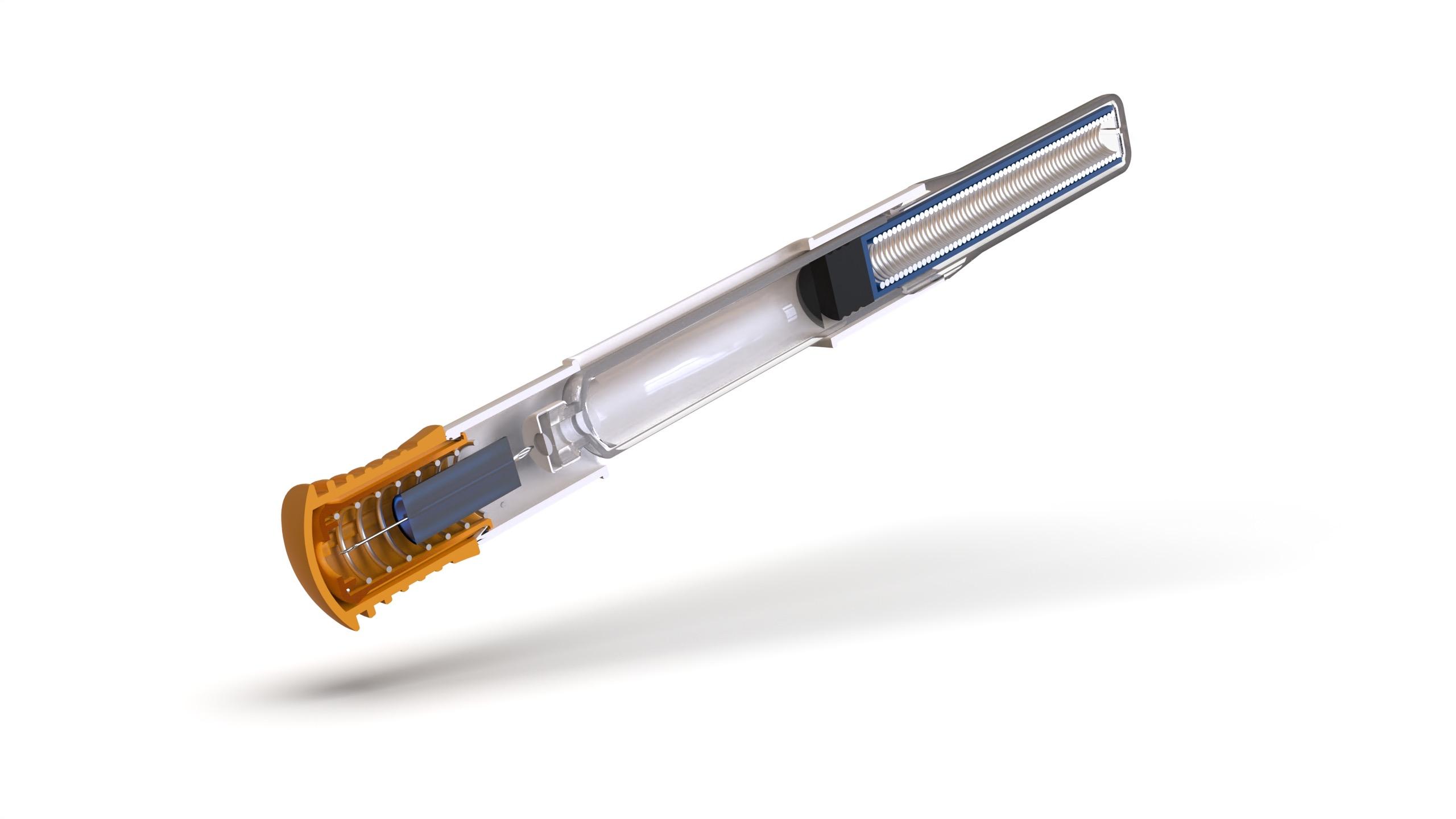
Figure 1: Illustration of autoinjector parameters for the definition of injection time, omitting losses in available force to bubble compression and friction.
Cambridge
CB4 0WS
CB4 0WS
St John’s Innovation Centre Cowley Road Cambridge
Cambridge CB4 0WS
United Kingdom
CB4 0WS
United Kingdom
United Kingdom
www.springboard.pro
DEFINING THE PARAMETERS OF AN AUTOINJECTOR
www.springboard.pro
www.springboard.pro ##
United Kingdom www.springboard.pro ##
##
##
Consider an autoinjector comprising a primary container with a liquid volume V and an internal diameter D (Error! Reference source not found.). For illustration, it is assumed that any bubble volume in the container vanishes once the container is pressurised, although this can be accounted for if needed. The liquid occupies a fraction of the container length L equivalent to the delivery stroke:
FIGURE CAPTIONS:
FIGURE CAPTIONS:
Consider an autoinjector comprising a primary container with a liquid volume V and an internal diameter D (Figure 1). For illustration, it is assumed that any bubble volume in the container vanishes once the container is pressurised, although this can be accounted for if needed. The liquid occupies a fraction of the container length L equivalent to the delivery stroke:
generates pressure within the container, which, due to the spring constant k, diminishes as delivery progresses. This case is true for most autoinjectors powered by helical compression springs or gas springs. In the event of a system providing constant force, such as an electronic driver or subliming substance, the delivery occurs under a near-steady state.
Consider an autoinjector comprising a primary container with a liquid volume V and an internal diameter D (Error! Reference source not found.). For illustration, it is assumed that any bubble volume in the container vanishes once the container is pressurised, although this can be accounted for if needed. The liquid occupies a fraction of the container length L equivalent to the delivery stroke:
FIGURE CAPTIONS:
FIGURE CAPTIONS:
���� = 4����/��������)
���� = 4����/��������)
In this example, the work required to deliver the drug is performed by the force of a compression spring, following Hooke's law, pushing on a rubber plunger stopper within the container:
Figure 1: Illustration of autoinjector parameters for the definition of injection time, omitting losses in available force to bubble compression and friction.
Figure 1: Illustration of autoinjector parameters for the definition of injection time, omitting losses in available force to bubble compression and friction.
Figure 1: Illustration of autoinjector parameters for the definition of injection time, omitting losses in available force to bubble compression and friction.
In this example, the work required to deliver the drug is performed by the force of a compression spring, following Hooke's law, pushing on a rubber plunger stopper within the container:
Figure 1: Illustration of autoinjector parameters for the definition of injection time, omitting losses in available force to bubble compression and friction.
In this example, the work required to deliver the drug is performed by the force of a compression spring, following Hooke’s law, pushing on a rubber plunger stopper within the container:
���� = ����* ��������
The force F exerted by the delivery system, after accounting for frictional losses (glide force Ff), creates a pressure P within the container proportional to its cross-sectional area A. This produces a flow rate Q through the needle proportional to the hydrodynamic resistance of the needle (length and diameter), as well as the effective viscosity of the fluid. It is assumed here that no back pressure is present and, therefore, that P within the container is equivalent to ΔP across the needle.
Figure 2: Illustration of the change from a parabolic flow profile to plug flow for a power -law fluid with decreasing flow behaviour index n.
���� = ����* ��������
Here, F is the force at a particular instance during delivery, ����* is the force at the start of delivery, k is the spring constant and x represents the spring extension, which, for simplicity, is assumed to correlate to the plunger stopper displacement. The system generates pressure within the container, which, due to the spring constant k, diminishes as delivery progresses. This case is true for most autoinjectors powered by helical compression springs or gas springs. In the event of a system providing constant force, such as an electronic driver or subliming substance, the delivery occurs under a near-steady state.
Figure 2: Illustration of the change from a parabolic flow profile to plug flow for a power -law fluid with decreasing flow behaviour index n.
Figure 2: Illustration of the change from a parabolic flow profile to plug flow for a power -law fluid with decreasing flow behaviour index n.
Figure 2: Illustration of the change from a parabolic flow profile to plug flow for a power -law fluid with decreasing flow behaviour index n.
Here, F is the force at a particular instance during delivery, ����* is the force at the start of delivery, k is the spring constant and x represents the spring extension, which, for simplicity, is assumed to correlate to the plunger stopper displacement. The system generates pressure within the container, which, due to the spring constant k, diminishes as delivery progresses. This case is true for most autoinjectors powered by helical compression springs or gas springs. In the event of a system providing constant force, such as an electronic driver or subliming substance, the delivery occurs under a near-steady state.
Figure 3: Illustration of the power law, Cross and Carreau apparent viscosity as a function of shear rate.
Figure 3: Illustration of the power law, Cross and Carreau apparent viscosity as a function of shear rate.
Figure 3: Illustration of the power law, Cross and Carreau apparent viscosity as a function of shear rate.
Figure 3: Illustration of the power law, Cross and Carreau apparent viscosity as a function of shear rate.
Here, F is the force at a particular instance during delivery, F0 is the force at the start of delivery, k is the spring constant and x represents the spring extension, which, for simplicity, is assumed to correlate to the plunger stopper displacement. The system
The viscosity and shear relationships for non-Newtonian fluids described by the power law, Carreau and Cross fluid models are shown in Table 1.5,6
Table 1: Definition of common Newtonian and non-Newtonian fluid models with examples
Table 1: Definition of common Newtonian and non-Newtonian fluid models with examples
The force F exerted by the delivery system, after accounting for frictional losses (glide force Ff), creates a pressure P within the container proportional to its cross-sectional area A. This produces a flow rate Q through the needle proportional to the hydrodynamic resistance of the needle (length and diameter), as well as the effective viscosity of the fluid. It is assumed here that no back pressure is present and, therefore, that P within the container is equivalent to ΔP across the needle.
The force F exerted by the delivery system, after accounting for frictional losses (glide force Ff), creates a pressure P within the container proportional to its cross-sectional area A. This produces a flow rate Q through the needle proportional to the hydrodynamic resistance of the needle (length and diameter), as well as the effective viscosity of the fluid. It is assumed here that no back pressure is present and, therefore, that P within the container is equivalent to ΔP across the needle.
Table 1: Definition of common Newtonian and non-Newtonian fluid models with examples Model Rheological
Table 1: Definition of common Newtonian and non-Newtonian fluid models with examples
Model Rheological equation
Haggen-Poiseuille
MODELLING NON-NEWTONIAN FLUIDS
MODELLING NON-NEWTONIAN FLUIDS
The viscosity and shear relationships for non-Newtonian fluids described by the power law, Carreau and Cross fluid models are shown in Error! Reference source not found. 5,6
The viscosity and shear relationships for non-Newtonian fluids described by the power law, Carreau and Cross fluid models are shown in Error! Reference source not found. 5,6
Defining Volumetric Flowrate
Defining Volumetric Flowrate
Table 1: Definition of common Newtonian and non-Newtonian fluid models with examples.
Non-Newtonian Behaviour
It is useful to initially define power law fluid behaviour, as it underpins both the Carreau and Cross fluid models. A power law fluid flow profile is not parabolic (plug flow) and affects its volumetric flow rate at a given differential pressure. The magnitude of shear dependency is governed by a flow behaviour index n, while the overall viscosity is regulated by the flow consistency index K. Unlike the Cross and Carreau models, the power law fluid equation for injection time can be analytically solved, as previously reported 7 The normalised transition from parabolic to plug flow, as the value of n decreases, is illustrated in Figure 2.
It is useful to initially define power law fluid behaviour, as it underpins both the Carreau and Cross fluid models. A power law fluid flow profile is not parabolic (plug flow) and affects its volumetric flow rate at a given differential pressure. The magnitude of shear dependency is governed by a flow behaviour index n, while the overall viscosity is regulated by the flow consistency index K. Unlike the Cross and Carreau models, the power law fluid equation for injection time can be analytically solved, as previously reported.7 The normalised transition from parabolic to plug flow, as the value of n decreases, is illustrated in Figure 2.
The local velocity of the liquid in a needle depends on the distance r from the centre axis. Here a definition of volumetric flow rate adapted from a method attributed to Weissenberg, Rabinowitsch, Mooney and Schofield (WRMS)5,6 is used, and combined with definitions for an autoinjector mechanism:
The analytical solution for injection time is found from the definition of the power law fluid volumetric flow rate:
The analytical solution for injection time is found from the definition of the power law fluid volumetric flow rate:
The local velocity of the liquid in a needle depends on the distance r from the centre axis. Here a definition of volumetric flow rate adapted from a method attributed to Weissenberg, Rabinowitsch, Mooney and Schofield (WRMS)5,6 is used, and combined it with definitions for an autoinjector mechanism:
The local velocity of the liquid in a needle depends on the distance r from the centre axis. Here a definition of volumetric flow rate adapted from a method attributed to Weissenberg, Rabinowitsch, Mooney and Schofield (WRMS)5,6 is used, and combined it with definitions for an autoinjector mechanism:
Expanding for I and substituting container diameter D for container radius R gives:
From this, an integral ���� is derived 6 It is this integral that requires solving to determine the volumetric flow rate for a specific fluid model:
Expanding for I and substituting container diameter D for container radius R gives:
From this, an integral ���� is derived 6 It is this integral that requires solving to determine the volumetric flow rate for a specific fluid model:
From this, an integral I is derived.6 It is this integral that requires solving to determine the volumetric flow rate for a specific fluid model:
Expanding for I and substituting container diameter D for container radius R gives:
From this, an integral ���� is derived 6 It is this integral that requires solving to determine the volumetric flow rate for a specific fluid model:
Substituting specific terms for τ and dτ followed by integration provides an analytical solution for a model of interest. In the case of a Newtonian fluid, this results in the familiar Hagge-Poiseuille equation:
Substituting specific terms for τ and dτ followed by integration provides an analytical solution for a model of interest. In the case of a Newtonian fluid, this results in the familiar Hagge-Poiseuille equation:
Substituting specific terms for τ and dτ followed by integration provides an analytical solution for a model of interest. In the case of a Newtonian fluid, this results in the familiar Hagge-Poiseuille equation:
Substituting specific terms for τ and d τ followed by integration provides an analytical solution for a model of interest. In the case of a Newtonian fluid, this results in the familiar Hagen-Poiseuille equation:
Non-Newtonian Behaviour
Non-Newtonian Behaviour
Non-Newtonian Behaviour
Non-Newtonian Behaviour
Where F is the applied force, D is the container diameter, d is the needle diameter, l is the needle length, K is the flow consistency index and n is the flow behaviour index. This is combined with the two equations describing the autoinjector to obtain a relation for plunger motion over time7 (note that k for spring index is similar in appearance to K the flow consistency index):
Where F is the applied force, D is the container diameter, d is the needle diameter, l is the needle length, K is the flow consistency index and n is the flow behaviour index. This is combined with the two equations describing the autoinjector to obtain a relation for plunger motion over time7 (note that k for spring index is similar in appearance to K the flow consistency index):
Where F is the applied force, D is the container diameter, d is the needle diameter, l is the needle length, K is the flow consistency index and n is the flow behaviour index. This is combined with the two equations describing the autoinjector to obtain a relation for plunger motion over time7 (note that k for spring index is similar in appearance to K the flow consistency index):
Where F is the applied force, D is the container diameter, d is the needle diameter, l is the needle length, K is the flow consistency index and n is the flow behaviour index. This is combined with the two equations describing the autoinjector to obtain a relation for plunger motion over time7 (note that k for spring index is similar in appearance to K the flow consistency index):
It is useful to initially define power law fluid behaviour, as it underpins both the Carreau and Cross fluid models. A power law fluid flow profile is not parabolic (plug flow) and affects its volumetric flow rate at a given differential pressure. The magnitude of shear dependency is governed by a flow behaviour index n, while the overall viscosity is regulated by the flow consistency index K. Unlike the Cross and Carreau models, the power law fluid equation for injection time can be analytically solved, as previously reported 7 The normalised transition from parabolic to plug flow, as the value of n decreases, is illustrated in Figure 2.
It is useful to initially define power law fluid behaviour, as it underpins both the Carreau and Cross fluid models. A power law fluid flow profile is not parabolic (plug flow) and affects its volumetric flow rate at a given differential pressure. The magnitude of shear dependency is governed by a flow behaviour index n, while the overall viscosity is regulated by the flow consistency index K. Unlike the Cross and Carreau models, the power law fluid equation for injection time can be analytically solved, as previously reported 7 The normalised transition from parabolic to plug flow, as the value of n decreases, is illustrated in Figure 2.
Where F is the applied force, D is the container diameter, d is the needle diameter, l is the needle length, K is the flow consistency index and n is the flow behaviour index. This is combined with the two equations describing the autoinjector to obtain a relation for plunger motion over time7 (note that k for spring index is similar in appearance to K the flow consistency index):
It is useful to initially define power law fluid behaviour, as it underpins both the Carreau and Cross fluid models. A power law fluid flow profile is not parabolic (plug flow) and affects its volumetric flow rate at a given differential pressure. The magnitude of shear dependency is governed by a flow behaviour index n, while the overall viscosity is regulated by the flow consistency index K. Unlike the Cross and Carreau models, the power law fluid equation for injection time can be analytically solved, as previously reported 7 The normalised transition from parabolic to plug flow, as the value of n decreases, is illustrated in Figure 2.
For the purpose of integration, this is simplified by introducing a constant C:
For the purpose of integration, this is simplified by introducing a constant C:
For the purpose of integration, this is simplified by introducing a constant C:
The analytical solution for injection time is found from the definition of the power law fluid volumetric flow rate:
The analytical solution for injection time is found from the definition of the power law fluid volumetric flow rate:
It is useful to initially define power law fluid behaviour as it underpins both the Carreau and Cross fluid models. A power law fluid flow profile is not parabolic (plug flow) and affects its volumetric flow rate at a given differential pressure. The magnitude of shear dependency is governed by a flow behaviour index n, while the overall viscosity is regulated by the flow consistency index K. Unlike the Cross and Carreau models, the power law fluid equation for injection time can be analytically solved, as previously reported.7 The normalised transition from parabolic to plug flow, as the value of n decreases, is illustrated in Figure 2.
Expanding for I and substituting container diameter D for container radius R gives:
For the purpose of integration, this is simplified by introducing a constant C:
= 2" )3#4$ %1+5 P 2 63#78R0// resulting in: 2: 2;
Integration over the stroke results in an analytical solution for injection time for a power law fluid from an autoinjector with a specific needle geometry and spring design:
The analytical solution for injection time is found from the definition of the power law fluid volumetric flow rate:
Integration over the stroke results in an analytical solution for injection time for a power law fluid from an autoinjector with a specific needle geometry and spring design:
For the purpose of integration, this is simplified by introducing a constant C
Integration over the stroke results in an analytical solution for injection time for a power law fluid from an autoinjector with a specific needle geometry and spring design:
Integration over the stroke results in an analytical solution for injection time for a power law fluid from an autoinjector with a specific needle geometry and spring design:
Expanding for gives:
Expanding for gives:
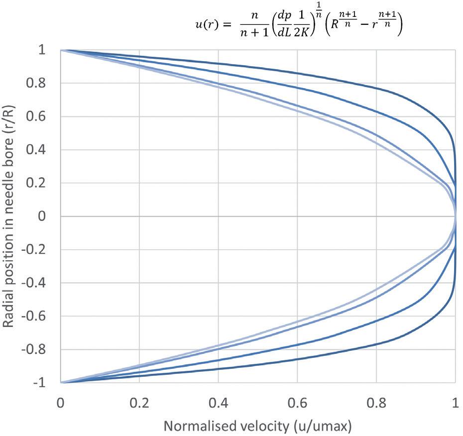

Integration over the stroke results in an analytical solution for injection time for a power law fluid from an autoinjector with a specific needle geometry and spring design:
Formulations With Time-Dependent Non-Newtonian Behaviour
Time-Dependent Non-Newtonian Behaviour
Cross and Carreau fluids are more complex, behaving as power law fluids at intermediate rates and Newtonian fluids at both high and low shear rates (Error! Reference source not found.). They require the definition of four-parameters including low-shear and high-shear viscosities (����
characteristic time λ and a flow behaviour index n
Formulations With Time-Dependent Non-Newtonian Behaviour
Cross and Carreau fluids are more complex, behaving as power law fluids at intermediate rates and Newtonian fluids at both high and low shear rates (Error! Reference source not found.). They require the definition of four-parameters including low-shear and high-shear viscosities (����* ,
characteristic time λ and a flow behaviour index n
Formulations With Time-Dependent Non-Newtonian Behaviour
characteristic time
and a flow behaviour index n
Finding an analytical solution as the one shown for a power law fluid is not possible because the relationship between flowrate and pressure drop needs to be defined implicitly, requiring a numerical solver. The two solutions start with the same definition from the WRMS method as before,4,5 where:
Cross and Carreau fluids are more complex, behaving as power law fluids at intermediate rates and Newtonian fluids at both high and low shear rates (Error! Reference source not found.). They require the definition of four-parameters including low-shear and high-shear viscosities (����
Finding an analytical solution as the one shown for a power law fluid is not possible because the relationship between flowrate and pressure drop needs to be defined implicitly, requiring a numerical solver. The two solutions start with the same definition from the WRMS method as before,4,5 where:
Cross and Carreau fluids are more complex, behaving as power law fluids at intermediate rates and Newtonian fluids at both high and low shear rates (Figure 3). They require the definition of four parameters including low- and high-shear viscosities (μ0,μ∞), a characteristic time λ and a flow behaviour index n
Cross and Carreau fluids are more complex, behaving as power law fluids at intermediate rates and Newtonian fluids at both high and low shear rates (Error! Reference source not found.). They require the definition of four-parameters including low-shear and high-shear viscosities (����
characteristic time λ and a flow behaviour index n
Finding an analytical solution as the one shown for a power law fluid is not possible because the relationship between flowrate and pressure drop needs to be defined implicitly, requiring a numerical solver. The two solutions start with the same definition from the WRMS method as before,4,5 where:
Carreau Fluid
Carreau Fluid
Finding an analytical solution as the one shown for a power law fluid is not possible because the relationship between flow rate and pressure drop needs to be defined implicitly, requiring a numerical solver. The two solutions start with the same definition from the WRMS method as before,4,5 where:
Finding an analytical solution as the one shown for a power law fluid is not possible because the relationship between flowrate and pressure drop needs to be defined implicitly, requiring a numerical solver. The two solutions start with the same definition from the WRMS method as before,4,5 where:
To solve the integral and calculate volumetric flowrate, the equation defining viscosity for a Carreau fluid is introduced, substituting
and
To solve the integral and calculate volumetric flowrate, the equation defining viscosity for a Carreau fluid is introduced, substituting
and
Figure 2: Illustration of the change from a parabolic flow profile to plug flow for a power-law fluid with decreasing flow behaviour index n
To solve the integral and calculate volumetric flowrate, the equation defining viscosity for a Carreau fluid is introduced, substituting
and
Carreau Fluid
fluid is introduced, substituting
For the purpose of integration, this is simplified by introducing a constant C:

Integration over the stroke results in an analytical solution for injection time for a ower law fluid
APPLICATION TO AN AUTOINJECTOR PROBLEM
These are substituted into I and solved.6 As with the Carreau model, only ����, is required to do this numerically using the equation:
In an autoinjector, Q can be converted to the rate of change of the plunger position over time dx/dt, which correlates to an incremental reduction in available delivery force. The computation of injection time for Cross and Carreau fluids requires an incremental, numerical approach.
% $ % at intermediate rates and Error! Reference source not found.). They shear viscosities (����* , ����$ ), a law fluid is not possible because the relationship between flowrate and pressure drop needs to be defined implicitly, requiring a numerical solver. The two solutions start with the same definition from the WRMS method as before,4,5 where:
Carreau Fluid
Carreau Fluid
Initially the autoinjector system is considered at x = 0 and t = 0. The procedure is to start with the determination of ΔP, γ w, I and, finally, flow rate Q at x(t = 0) = 0 and F(x = 0) = F0. Q is subsequently converted into a change of plunger stopper position over an increment. The new level of force at this spring extension is used to again calculate ΔP, γ w, I and Q. Injection time is the sum of time intervals until the point where x = L, with smaller increments being preferable.
In an autoinjector, Q can be converted to the rate of change of the plunger position over time dx/dt, which correlates to an incremental reduction in available delivery force. The computation of injection time for Cross and Carreau fluids requires an incremental, numerical approach.
Initially the autoinjector system is considered at x = 0 and t = 0. The procedure is to start with the determination of ΔP, ����, , I and, finally, flowrate Q at x(t=0) = 0 and F(x=0) = F0 Q is subsequently converted into a change of plunger stopper position over an increment. The new level of force at this spring extension is used to again calculate ΔP, ����, , I and Q. Injection time is the sum of time intervals until the point where x = L, with smaller increments being preferable.
If the autoinjector supplies a constant force, the system can be treated as a steady state over the interval from x = 0 to x = L
If the autoinjector supplies a constant force, the system can be treated as a steady state over the interval from x = 0 to x = L.
To solve the integral and calculate volumetric flow rate, the equation defining viscosity for a Carreau fluid is introduced, substituting δ= (μ0 -μ∞) and n -1 = n’:
To solve the integral and calculate volumetric flowrate, the equation defining viscosity for a Carreau fluid is introduced, substituting ���� = (����* ����$ ) and ���� 1 =
The determination of the best fitting model, as well as of the relevant model parameters, is achieved by fitting the models presented in Error! Reference source not found. to data of the log of the dynamic viscosity against the log of the shear rate. Solvers in programming languages such as MATLAB or Python, as well as other commercially available rheology software, can be used for this. Before analysing the data, it is important to consider if the experimental conditions cover a sufficiently large span of shear rates. This is to ensure that any Newtonian to non-Newtonian
Substituting for τ and dτ into the definition of integral I, changing the integration limits and solving analytically results in a large equation.6
Substituting for ���� ad �������� into the definition of integral I, changing the integration limits and solving analytically results in a large equation.6
Substituting for ���� ad �������� into the definition of integral I, changing the integration limits and solving analytically results in a large equation.6
Substituting for ���� ad �������� into the definition of integral I, changing the integration limits and solving analytically results in a large equation.6
The only thing needed to calculate ���� is ����, which can be obtained numerically using:
The only thing needed to calculate I is γ w which can be obtained numerically using:
The only thing needed to calculate ���� is ����, which can be obtained numerically using:
The only thing needed to calculate ���� is ����, which can be obtained numerically using:
The determination of the best fitting model, as well as of the relevant model parameters, is achieved by fitting the models presented in Table 1 to data of the log of the dynamic viscosity against the log of the shear rate. Solvers in programming languages, such as MATLAB or Python, as well as other commercially available rheology software, can be used for this. Before analysing the data, it is important to consider if the experimental conditions cover a sufficiently large span of shear rates. This is to ensure that any Newtonian to non-Newtonian transitions are identified, and that the shear rates are representative of those experienced within an autoinjector.
Cross Fluid
Cross Fluid
The solution of a cross fluid is similar:
The solution of a cross fluid is similar:
The solution of a cross fluid is similar:
The solution of a Cross fluid is similar:
The models provided in this article are a step towards a common toolbox for drug delivery device design and process development. Understanding the non-Newtonian behaviour of formulations is essential for ensuring the efficacy and safety of advanced therapies.
These are substituted into I and solved.6 As with the Carreau model, only ����, is required to do this numerically using the equation:
These are substituted into I and solved.6 As with the Carreau model, only ����, is required to do this numerically using the equation:
These are substituted into I and solved.6 As with the Carreau model, only ����, is required to do this numerically using the equation:
These are substituted into I and solved.6 As with the Carreau model, only γ w is required to do this numerically using the equation:
APPLICATION TO AN AUTOINJECTOR PROBLEM
APPLICATION TO AN AUTOINJECTOR PROBLEM
APPLICATION TO AN AUTOINJECTOR PROBLEM
In an autoinjector, Q can be converted to the rate of change of the plunger position over time dx/dt, which correlates to an incremental reduction in available delivery force. The computation of injection time for Cross and Carreau fluids requires an incremental, numerical approach.
In an autoinjector, Q can be converted to the rate of change of the plunger position over time dx/dt, which correlates to an incremental reduction in available delivery force. The computation of injection time for Cross and Carreau fluids requires an incremental, numerical approach.
“Understanding the non-Newtonian behaviour of formulations is essential for ensuring the efficacy and safety of advanced therapies.”
In an autoinjector, Q can be converted to the rate of change of the plunger position over time dx/dt, which correlates to an incremental reduction in available delivery force. The computation of injection time for Cross and Carreau fluids requires an incremental, numerical approach.
Initially the autoinjector system is considered at x = 0 and t = 0. The procedure is to start with the determination of ΔP, ����, , I and, finally, flowrate Q at x(t=0) = 0 and F(x=0) = F0. Q is subsequently converted into a change of plunger stopper position over an increment. The new level of force at this spring extension is used to again calculate ΔP, ����, , I and Q. Injection time is the sum of time intervals until the point where x = L, with smaller increments being preferable.
Initially the autoinjector system is considered at x = 0 and t = 0. The procedure is to start with the determination of ΔP, ����, , I and, finally, flowrate Q at x(t=0) = 0 and F(x=0) = F0 Q is subsequently converted into a change of plunger stopper position over an increment. The new level of force at this spring extension is used to again calculate ΔP, ����, , I and Q. Injection time is the sum of time intervals until the point where x = L, with smaller increments being preferable. ���� = 2M 2;
Initially the autoinjector system is considered at x = 0 and t = 0. The procedure is to start with the determination of ΔP, ����, , I and, finally, flowrate Q at x(t=0) = 0 and F(x=0) = F0 Q is subsequently converted into a change of plunger stopper position over an increment. The new level of force at this spring extension is used to again calculate ΔP, ����, , I and Q. Injection time is the sum of time intervals until the point where x = L, with smaller increments being preferable.
If the autoinjector supplies a constant force, the system can be treated as
If the autoinjector supplies a constant force, the system can be treated as a steady state over the
By embracing standardised modelling approaches and considering the complexities of non-Newtonian behaviour early in the development process, researchers and developers can de-risk future device development. This becomes more relevant as the industry focuses on established platform devices that may have to deliver increasingly sophisticated formulations in the future.
Springboard, part of Sanner Group since 2024, is an engineering company that specialises in the design and development of new products and technologies in the field of medtech and drug delivery devices, resolving technical challenges and decreasing time to market.
1. “The rise of biologics: Emerging trends and opportunities”. White Paper, CAS, 2023.
2. Baryakova TH et al, “Overcoming barriers to patient adherence: the case for developing innovative drug delivery systems”. Nat Rev Drug Discov, 2023, Vol 22(5), pp 387–409.
3. Paul D et al, “Artificial intelligence in drug discovery and development”. Drug Discov Today, 2021, Vol 26(1), pp 80–93.
4. Jindal AB et al, “Long-acting parenteral drug delivery systems for the treatment of chronic diseases”. Adv Drug Deliv Rev, 2023, Vol 198, Article 114862.
5. Skelland AHP, “Non-Newtonian Flow and Heat Transfer”. Wiley, New York, 1966.
6. Sochi T, “Analytical solutions for the flow of Carreau and Cross fluids in circular pipes and thin slits”. Rheologica Acta, 2015, Vol 54, pp 745–756.
7. Vilaplana M, Vasiev A, White S, “Function-Based Primary Packaging Design for Injecting Viscous Non-Newtonian Formulations”. ONdrugDelivery Magazine, Issue 101 (Oct 2019), pp 20–25.
Alex Vasiev, PhD, is an experienced engineer specialising in medical device development. With a broad multidisciplinary background, Dr Vasiev has focused on drug delivery, contributing to the development of novel microcarriers, hydrogel matrices, patch pumps, inhalers and several high-viscosity autoinjectors. He currently holds the position of Principal Biomedical Engineer at Springboard, having previously served as Manager of Device Development at Oval Medical Technologies (now SMC Ltd).
• Digital & Connected Health—Novel
• A System-Wide Approach to Stability of
• Wearable Devices and the Changing Paradigm in Drug Delivery
• Meeting Regulatory Expectations for PFS and Auto-Injectors
• Human Factors—Translating User Research to Actionable Product Specification
Here, Paul Scannell, Senior Director at West Pharmaceutical Services, explains how to safely navigate the regulatory landscape for co-packaged drug-device combination products.
In purely mathematical terms, the consequence of combining two elements together is a simple exercise in arithmetic. In this scenario, the whole can be viewed as the aggregate of its parts. However, in the right circumstances, additional value can be realised when combining the right elements and deliberately maximising the synergy between the distinct parts based on an understanding of their resulting interaction.
One example of such holistic synergy is combination products. Combination products consist of two or more regulated products (i.e. a medicinal product, a medical device or a biological product) which, when brought together, can result in an enhanced whole – one that delivers a more effective, more efficient or more accessible treatment pathway for patients.
These benefits are reflected in the fact that a quarter of approved medicines in the EU include a medical device component, providing an indication of the increasingly
“Combination products, by their very nature, are interdisciplinary products and, consequently, from a regulatory perspective, can present various layers of complexity.”
influential role of combination products within modern healthcare systems and their increasing importance to patients.1 These products have established this position thanks to ongoing advancements in drug delivery technologies expanding device capabilities and because of underlying shifts in healthcare trends. For example, the drive to enable greater levels of self-care and for treatments to be delivered in non-clinic environments, including the home, can only be made possible if patients or caregivers have access to both the required medicine and an accessible, simple method of administration. However, combining a medical device and a medicinal product is not a simple arithmetic exercise. Combination products, by their very nature, are interdisciplinary products and, consequently, from a regulatory perspective, can present various layers of complexity. The European regulatory environment for combination products, which is markedly different from the system in the US, necessitates an intimate understanding of two separate, yet closely linked, regulatory frameworks that must be navigated in all their complexity to successfully bring a combination product through development and onto the European market (Figure 1). Specifically, these regulatory frameworks are the European Medical Device Regulation (MDR), Regulation (EU) 2017/745 and the Medicinal Products Directive (MPD), 2001/83/EC.

Paul Scannell Senior Director E: paul.scannell@westpharma.com
West Pharmaceutical Services, Inc
530 Herman O West Drive
Exton PA 19341
United States
www.westpharma.com
The MDR is a new regulatory framework, which became fully applicable from May 26, 2021, replacing the Medical Device Directive (MDD) 93/42/EEC. The goal of the MDR was to establish and ensure a robust, transparent and sustainable regulatory framework, and to maintain a high level of safety while also supporting innovation. As with the introduction of any new piece of legislation, challenges will inherently be encountered in implementation, and this holds true in the case of the MDR.2 This is evidenced by the extension of the transition period for medical devices previously certified in accordance with the MDD to be re-certified in accordance with the MDR.3 While this deadline has shifted for some device types, reflecting the challenges in conforming to this updated regulatory framework, the unintended consequences and regulatory uncertainty introduced by the MDR have important implications for owners of co-packaged combination products.
The regulatory process for co-packaged combination products may initially appear straightforward. Simply put, the medicinal product requires marketing authorisation alongside evidence that the co-packaged device is compliant with the entirety of the MDR (i.e. CE-marked) before the combined product is placed on the market.4 However, therein lies the challenge for co-packaged combination products: they face a duality of predominantly independent approval processes. The EU does not have an integrated approach in the evaluation,
“The associated regulatory challenges are particularly pronounced in the case of medical devices subject to a first CE marking in parallel with the medicinal product marketing authorisation.”
as well as the lifecycle management, of such co-packaged combination products, and lacks comprehensive coordination between the medicinal product and medical device regulatory frameworks.
The associated regulatory challenges are particularly pronounced in the case of medical devices subject to a first CE marking in parallel with the medicinal product marketing authorisation. For what is effectively placed on the market as one combined product, two separate applications must be made to two distinct and disconnected regulatory bodies under two approval timeframes that are not co-ordinated. The thresholds for co-ordinating successful applications between the medicinal product manufacturer and the medical device manufacturer can therefore be seen as higher, while the potential for unintended points of conflict and the risks impacting approval success are increased.
These risks can be mitigated by using a medical device that has already received its CE certification. The medicinal product manufacturer must, however, ensure that the intended use of the medical
device mirrors the intended use when co-packaged with the medicinal product. Furthermore, the medicinal product manufacturer should be cognisant of the status of the medical device’s CE mark as it is their responsibility, when submitting a MAA, to ensure that the medical device(s) co-packaged with the medicinal product is in compliance with the MDR (or the MDD if applicable) before the combined product is placed on the market.4 However, where the device has been CE marked in accordance with the MDD and is availing of the MDR transitional provisions, the marketing authorisation holder (MAH) should inform itself of the device manufacturer’s transition plan to CE marking under the MDR to ensure that the device can continue to be placed on the market once the applicable transition timeframe has expired.
Where the intended device to be co-packaged has not yet been CE marked, the co-packaged device must comply with the MDR, and the challenges that exist for standalone medical devices (i.e. devices placed on the market in their own right) are equally applicable.2 These challenges are further compounded for co-packaged combination products under the dual regulatory framework and are exposed early on in development.
When it comes to premarket clinical studies for co-packaged combination products, for example, no current process exists to allow for an integrated and streamlined regulatory submission and approval. The medical device and medicinal product are, again, subject to two separate regulatory frameworks governing clinical studies: the MDR and the Clinical Trial Regulation (CTR) EU No 536/2014 respectively.
Similar to the CTR, the MDR also provides for a co-ordinated assessment procedure for clinical investigations of medical devices in line with Article 78. However, in lieu of a fully functional EUDAMED, no co-ordinated procedure is currently available, thereby necessitating individual authorisation by each member state in which the clinical investigation is to be conducted. The lack of a co-ordinated assessment for a medical device therefore negates the efficiencies brought about by the CTR in the case of premarket co-packaged combination product clinical studies. In acknowledgement of this disconnect, for co-packaged and other types of combined studies, the European Commission has signalled its intent to analyse the root causes of the challenges encountered by sponsors in conducting combined studies and to identify possible solutions to these challenges through the COMBINE project.5
While solutions are being sought in this area, challenges remain in others. When it comes to product approval assessments (i.e. medicinal product marketing authorisation and medical device conformity assessment), the parallel requirements for medicinal products and medical devices can result in duplication
“When it comes to product approval assessments, the parallel requirements for medicinal products and medical devices can result in duplication of reviews and inconsistencies in feedback from regulatory bodies.”
of reviews and inconsistencies in feedback from regulatory bodies. Applicants could be left with potentially contradictory strands of information relating to, for example, clinical evaluations and risk assessments, all of which might be understood when applied to a device in isolation but do not offer a definitive, coherent perspective on a combination product.
One specific area that often results in inconsistent regulatory obligations is the regulatory requirements for labelling, which must also be met independently for both device and medicinal product, despite the obvious need for them to be consistent and complementary. Separation of these processes can introduce the risk of confusion or contradiction, underlining the need to maintain a unified approach.
Furthermore, there is no defined duration for medical device conformity assessment leading to CE marking. This contrasts with the structured approval timescales for medicinal products, resulting in a potential misalignment that can trigger unpredictable complications or delays to product launches.
Following launch, challenges with the dual frameworks for medical device and medicinal product regulations do not go away. One example is the potential for pharmaceutical companies to be positioned in the role of an economic operator under the MDR (i.e. distributor or importer), further to the requirement to adhere to the good distribution practice guidelines for the pharmaceutical supply chain. This relates to the fact that, despite a co-packaged drug-device combination being registered as a medicinal product – implying that regulations for medicinal products should take precedence – the co-dominant requirements of the MDR also apply and necessitate an intimate understanding of the supply chain, not just of the co-packaged product but also of the medical device part.
In addition, there is no integration between the pharmacovigilance and vigilance systems for each of the respective elements, resulting in a two-pronged approach for what is effectively a single product. Furthermore, any subsequent variations to the product must be managed in the absence of a well-defined and clearly integrated post-market change engagement pathway, with potential for complication and delays.
Another area where there is a divergence between the two regulatory systems is in scientific advice. The aim of medicinal product scientific advice, at any stage of a medicine's development, is to provide prospective regulatory and scientific guidelines to help developers on the most appropriate path to generate robust evidence on a medicine's benefits and risks so that no major objections regarding the design of the tests are likely to be raised during the evaluation of the MAA.6 Notified bodies, however, are precluded from providing similar advice during the development of a medical device. Pre-submission dialogues are therefore essential to set the level of device evidence expectations and would improve the quality and correctness of submissions for conformity assessment. Efforts are being made in this area through the EMA in the form of a scientific advice pilot for high-risk medical devices regarding clinical development strategies and clinical investigation proposals.7 However, more concerted and co-ordinated efforts are required to help address some of the unique and broader challenges faced by developers (both medicinal product and medical device) of combination products.
While there are initial attempts at co-ordinating a dual regulatory framework for co-packaged combination products, including the proposed reform to the pharmaceutical legislation,8 it is crucial to understand the subtle details of this specific regulatory environment to facilitate the regulatory journey, identifying potential problems ahead of time and guaranteeing successful market access.
As a leading provider of devices that are frequently co-packaged with medicines to create effective non-integral combination products, West’s regulatory team is experienced in overcoming specific challenges that may occur due to unintended consequences of the MDR on co-packaged combination products, working with pharma partners to provide valuable insights into how to effectively address any issues. In terms of process, insights from device partners can help to improve planning efficiency. They can bring attention to areas that are likely to encounter challenges or delays and ensure that crucial results are prioritised from the beginning. Furthermore,
a partnership approach allows information requests to be managed concurrently and in parallel, facilitating responses that are consistent at an overarching product level and avoiding late-stage iterations.
In an ideal world, the need to navigate such complex matters would not be so demanding and the regulatory framework affecting co-packaged combination devices would be more unified, as it is in the US. Indeed, West is among the industry voices advocating for the EU to improve the regulatory framework for co-packaged combination products while retaining absolute focus on effectiveness and patient safety. As it stands, both new and existing co-packaged combination products destined for the European market continue to be burdened with a fragmented and opaque regulatory framework.
The impact of this situation is felt not only by applicants but also potentially by patients through time-to-market delays, aborted submissions or even withdrawal of products from the market – all of which can erode momentum behind bigger picture ambitions for innovative, cost-efficient treatments that can empower patients to take greater control of their own care and ease pressures on healthcare systems.
To mitigate these risks and adapt to the changing needs of the industry, it is crucial that the owners of co-packaged combination products consider collaboration as a primary strategy. Put simply, if devices are integral to positive patient outcomes, then device partners must play an integral role to ensure regulatory compliance is achieved in the most effective way.
They can be seen as a catalyst and navigational aid, streamlining the process and optimising the time, cost and effort involved in tandem with pharmaceutical partners – a unified, integrated approach that undoubtedly delivers more than the sum of its parts.
West Pharmaceutical Services is a leading provider of innovative, high-quality injectable solutions and services. As a trusted partner to established and emerging drug developers, West helps to ensure the safe, effective containment and delivery of life-saving and life-enhancing medicines for patients. With 10,000 team members across 50 sites worldwide, West helps to support customers by delivering approximately 47 billion components and devices each year.
1. “Regulatory Road To Innovation”. Report, EFPIA, Mar 2022.
2. “The Future of Europe’s Medical Technology Regulations”. Web Page, MedTech Europe, accessed Apr 2024.
3. “Regulation (EU) 2023/607 of the European Parliament and of the Council of 15 March 2023 amending Regulations (EU) 2017/745 and (EU) 2017/746 as regards the transitional provisions for certain medical devices and in vitro diagnostic medical devices”. European Parliament, Mar 2023.
4. “Questions & Answers for applicants, marketing authorisation holders of medicinal products and notified bodies with respect to the implementation of the Medical Devices and In
Vitro Diagnostic Medical Devices Regulations ((EU) 2017/745 and (EU) 2017/746)”. EMA, Nov 2023.
5. “Combined Studies”. Web Page, EC, accessed Apr 2024.
6. “Scientific advice and protocol assistance”. Web Page, EMA, accessed Apr 2024.
7. “EMA pilots scientific advice for certain high-risk medical devices”. Press Release, EMA, Feb 27, 2023.
8. “Reform of the EU pharmaceutical legislation”. Web Page, EC, accessed April 2024.
Paul Scannell is Senior Director with West Pharmaceutical Services and leads the European Regulatory Affairs Office with regulatory responsibilities for delivery system medical devices and combination products for European and Eurasian Economic Union markets. Mr Scannell has 19 years of experience across medical device and combination product regulatory affairs gained through his work in industry, consulting, Notified Body (NSAI) and Competent Authority (HPRA). Mr Scannell also sits on a number of industry regulatory associations and task forces with a focus on combination products. He has an undergraduate degree in Mechanical Engineering and a PhD in Biomechanics from the University of Dublin, Trinity College (Ireland). He also holds a master’s degree in Management from University College Cork (Ireland).

The Vial Adapter™ transfer device is a single-use, sterile, medical device intended for the transfer of drugs contained in vials. Puncturing the elastomeric closure of a vial is achieved by means of an integral plastic spike located in the center of the vial adapter. The device plastic package and cover are designed to limit direct contact, reduce potential for contamination, and to assist in attaching the device to the drug vial.

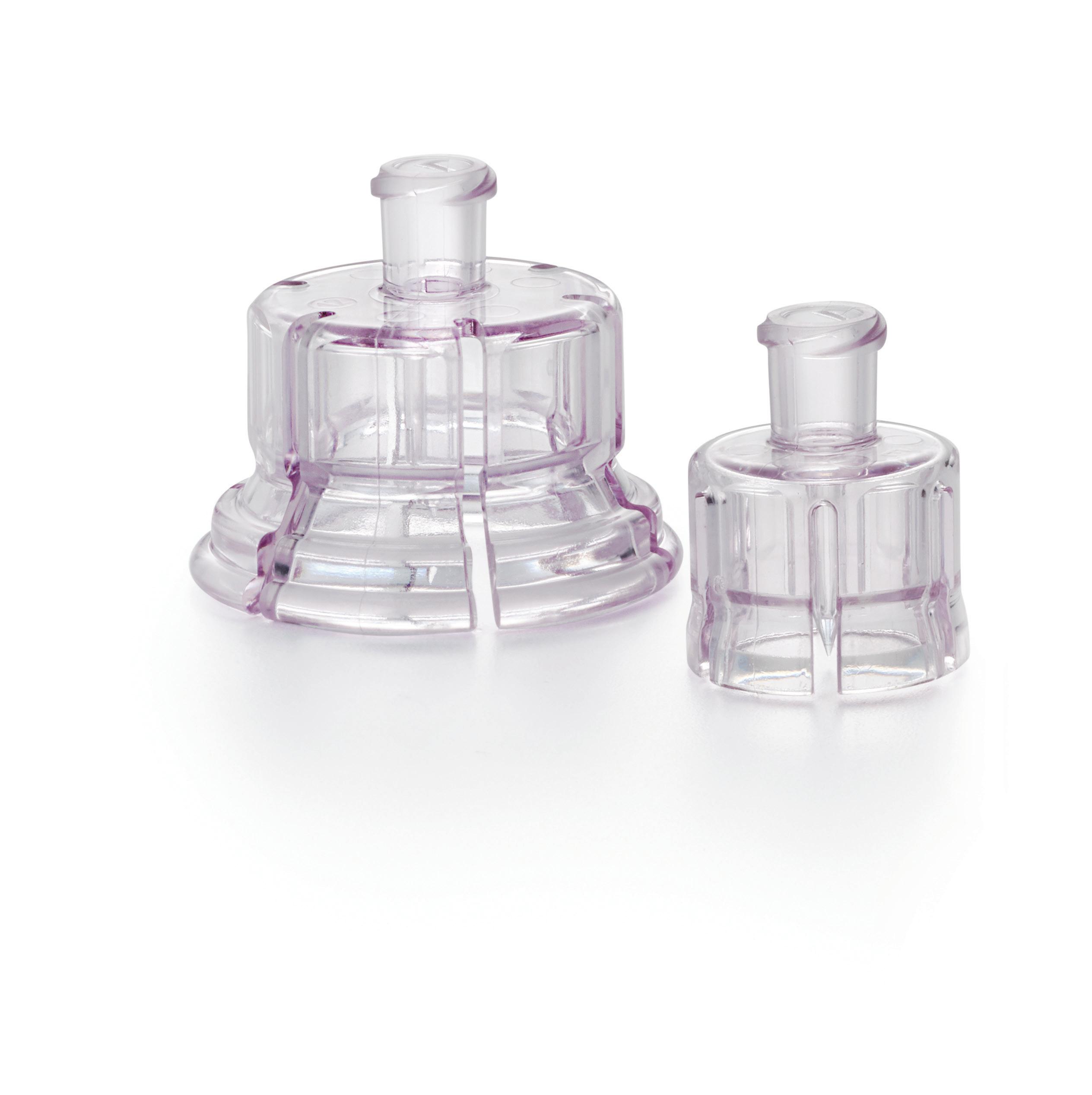
Important product and safety information for Vial Adapter Systems: www.westpharma.com/products/vial-adapter-systems/vial-adapters

In this article, Lucas Foerster, Product Manager Lab Weighing Applications at Sartorius Lab Instruments, and Dieter Peissig, Active Medical Device Expert at B. Braun Melsungen, explore the critical factors in choosing the right balance for infusion pump performance validation and discuss potential sources of error.
Precision in medical device technology is not just a goal – it is a necessity. Infusion pumps, which are integral to delivering life-saving treatments, must always operate with the utmost accuracy, as even the slightest deviation can have profound consequences. As these devices become more advanced, achieving precision levels as low as 0.01 mL/h, the margin for error narrows, particularly in sensitive applications such as neonatal care.
To safeguard against these risks, infusion pumps are subjected to stringent testing protocols. Gravimetric assessments, as outlined in standards such as IEC 60601-2-24 and technical reports such as AAMI TIR-101, are a cornerstone of
this process. However, these tests present unique challenges, especially when it comes to the balance’s ability to detect minute changes at low flow rates and to respond swiftly at higher ones.
When choosing the right balance for pump performance validation, there are a number of critical factors to consider. It is also important to understand the potential sources of error that can impact measurement results when using a test setup in accordance with IEC 60601-2-24 (Figure 1) or AAMI TIR-101. In collaboration with B. Braun Melsungen, Sartorius has gleaned insights into how to minimise these errors, ensure reliable flow rate checks and, ultimately, enhance patient safety.
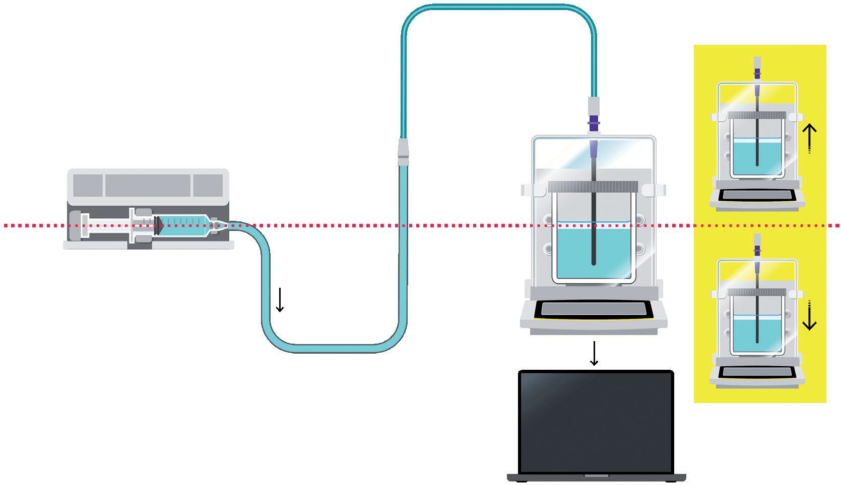
Figure 1: Set-up structure according to IEC 60601-2-24.

Lucas Foerster
Product Manager Lab Weighing Applications T: +49 1517 193336
E: lucas.foerster@sartorius.com
Sartorius Lab Instruments GmbH & Co. KG Otto-Brenner-Straße 20 37079 Goettingen Germany www.sartorius.com

Dieter Peissig Active Medical Device Expert T: +49 5661 713740
E: dieter.peissig@bbraun.com
B. Braun Melsungen AG Schwarzenberger Weg 21 34212 Melsungen Germany www.bbraun.com
Choosing the right balance is crucial for validating pump performance while meeting IEC 60601-2-24 and AAMI TIR101 standards. Three key factors to consider are:
• Readability/Resolution: This refers to the smallest measurable graduation on the balance’s scale. It indicates accuracy and the ability to detect small weight differences. Different types of balance offer varying levels of precision, from precision balances (1 mg) to microbalances (0.001 mg). TIR101 provides resolution recommendations for different flow rates.
• Capacity: This indicates the maximum weight a balance can accurately record. It is important for maintaining precision and avoiding damage. Higher capacities are recommended for testing infusion and syringe pumps, enabling longer test durations without frequent emptying.
• Linearity Deviation: This measures how accurately values align along a straight line across a weight range, indicating consistency and precision. Smaller deviations indicate better accuracy in maintaining proportionality between displayed and measured weights.
The balances recommended by Sartorius, according to AAMI TIR101, can be found in Table 1. For flow rates below 0.1 mL/h it recommends the high-capacity microbalance MCA66S (Figure 2) with a capacity of 61 g and a resolution of 1 µg.
Measurement
Balance (nominal capacity > 1000 mL/h)
Balance (nominal capacity 10 mL/h to 1000 mL/h) 0.0001
Balance (nominal capacity 0.1 mL/h to 10 mL/h)
Balance (nominal capacity < 0.1 mL/h)
0.00001
0.000001
Precision balance MCA5203S or MCA14202S (0.01 g)
Analytical balance MCA524S
Ultra-high-resolution semi-microbalance MCA225S
Ultra-high-resolution microbalance MCA66S
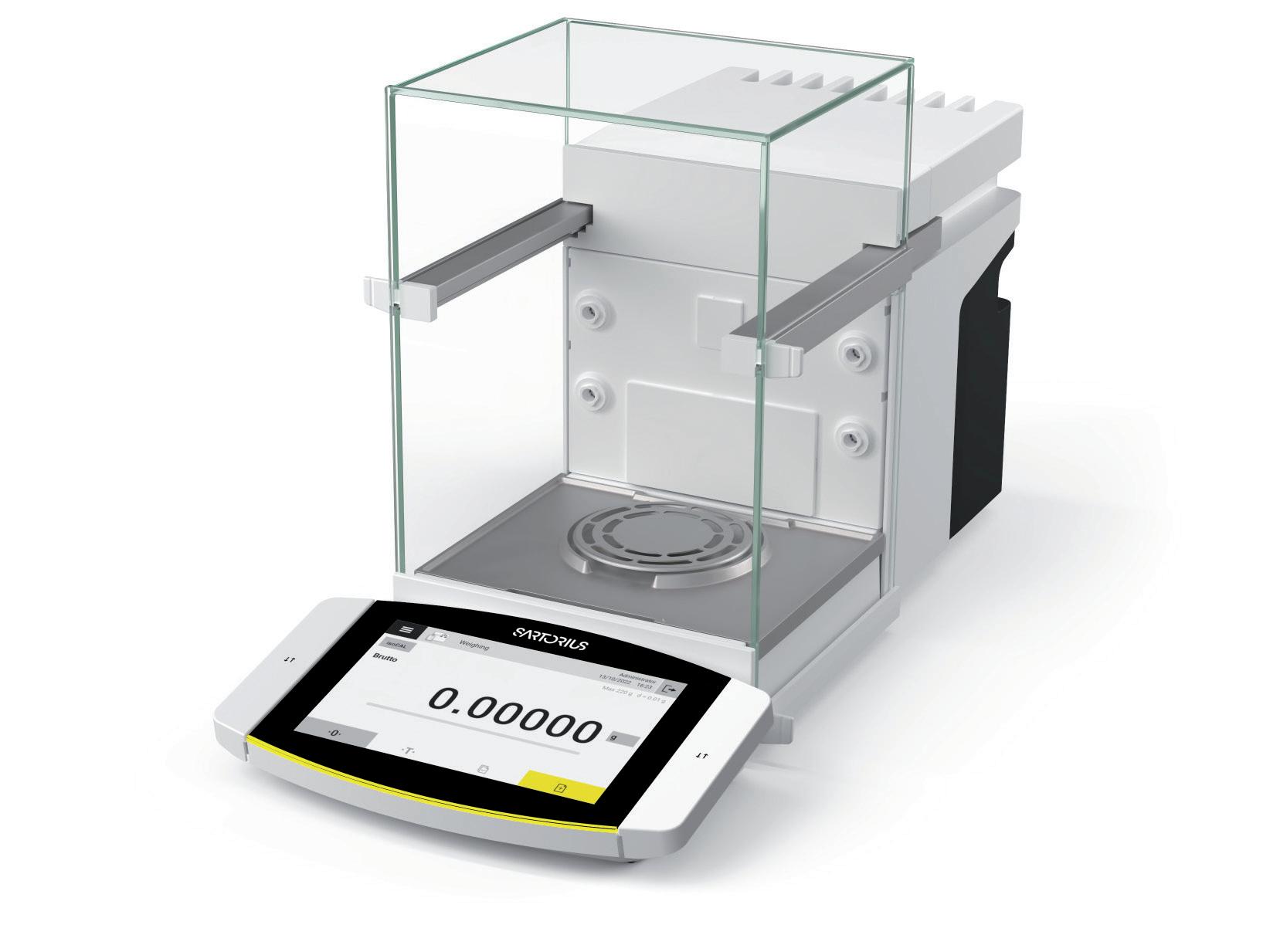
This section looks at potential sources of error on the measurement side. The following possible sources of error are examined:
• Balance drift
• Temperature change
• Relative humidity change
• Dynamic weighing
• Displacement of the cannula in the sample solution
• Electrostatic.
The various sources of error are interpreted in order to clarify how each effect can be minimised or understood so that a reliable result can be obtained in the flow-rate check.
Temperature and humidity changes can cause balance drift, an unwanted change in weight value without additional dosing. This phenomenon is influenced by environmental factors, with temperature fluctuations playing a significant role. Vibrations may also contribute to balance drift.
It has been observed that, generally, balance drift only has a significant influence on flow rate measurement results at dosing rates of less than 10 mL/h.
B. Braun Melsungen has intensively studied the balance drift of semi-microbalances (resolution of 0.01 mg). Nine semimicrobalances were used for the study, which recorded a measured value every 30 seconds over a period of 40 hours. A weight of 135 g was used as a preload.
Figure 2: Cubis® II high-capacity microbalance. Aligned with AAMI TIR101 for tests with flowrates < 0.1 mL/h.
“Generally, balance drift only has a significant influence on flow rate measurement results at dosing rates of less than 10 mL/h.”
The results were plotted by showing the change in weight in mg on the Y-axis against time on the X-axis (Figure 3). It was noticeable that the curves on the different balances were remarkably similar (maximum change of 0.4 mg, equivalent to 40 digits), indicating that external influences were responsible for the observed changes and they were not generated by individual balances.
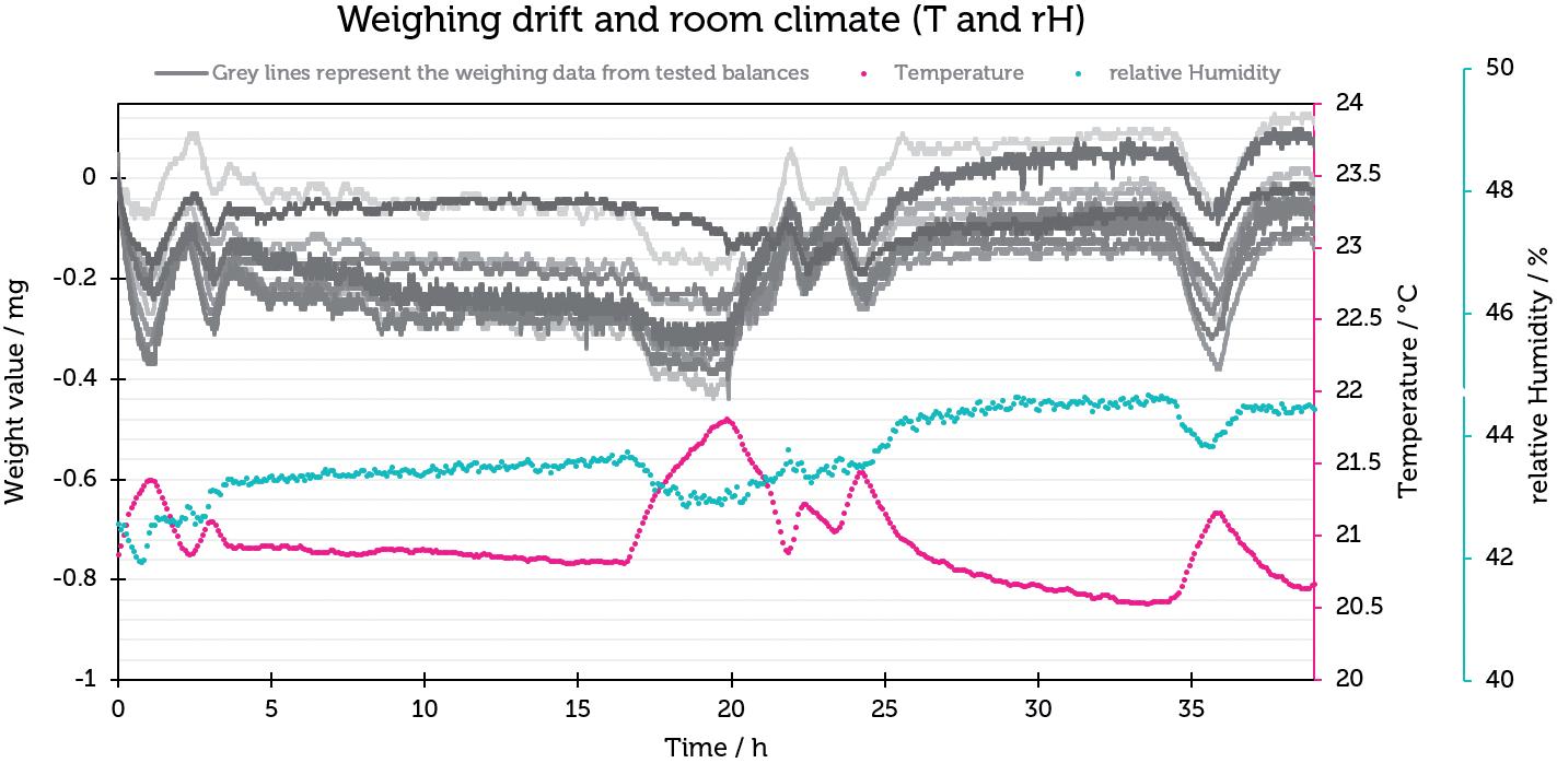
To quantify the relationship between the weighing drift and the flow-rate determination, the measured values, which contained measurement errors resulting from the weighing drift, were converted to a flow rate of 1 mL/h. The results are
shown in Figure 4 and illustrate that the influence of the balance drift in this particular case resulted in an error of 0.8±0.4%, which indicates that the balance drift plays a subordinate role in the measurement of flow rates.
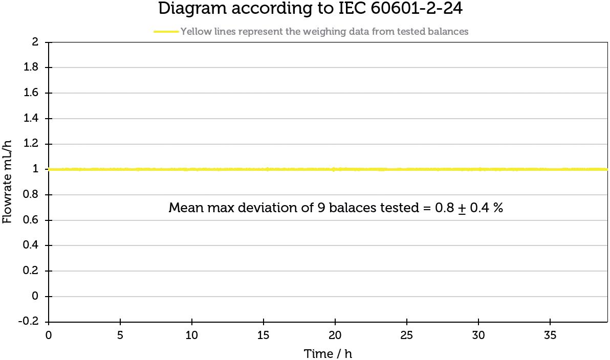
“The greatest influence on balance drift can be minimised by maintaining a constant room climate (including humidity and temperature).”
To investigate their correlation, the information from the indoor climate recording was linked to the weighing data in diagrams. First, room humidity was looked at. A direct correlation can be seen here – the measured weight value increases with increasing humidity.
Temperature is also shown in Figure 3. Interestingly, there is an opposite effect compared with humidity – as the temperature increases, the weight value decreases, and vice versa. The effect of temperature change plays a much greater role than humidity.
In summary, the greatest influence on balance drift can be minimised by maintaining a constant room climate (including humidity and temperature). In addition, it is advisable to use the balance close to its optimum working range and to avoid exposure to vibrations in the vicinity of the balances.
Beyond that, the effect of balance drift (0.8± 0.4%) could be illustrated. Under stable temperature and humidity, the influence of balance drift is minimal. It is important to emphasise that the Cubis® and Cubis® II balances have a monolithic weighing system, which reduces the scale drift to a minimum compared with conventional weighing systems with hundreds of individual parts.
To better understand the quality of measurement results from the Sartorius Cubis® semi-microbalance in the dynamic weighing range, B. Braun Melsungen carried out a test run with a high-precision pulsation-free pump (Cetoni Nemesys
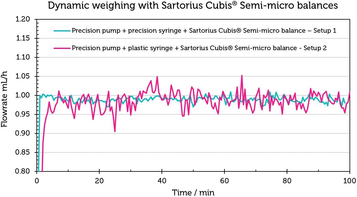
pump), a precision syringe (Hamilton glass syringe) and the Sartorius semi microbalance, referred to as Set-up 1 (Table 2).
The results of this test should show that a Sartorius Cubis® semi-microbalance can fulfil the required accuracy according to ISO 7886-2 and IEC 60601-2-24. In addition, the Hamilton syringe was replaced with a disposable plastic syringe in a second experiment (Set-up 2) in order to check to which extent the accessories of the measurement set-up could contribute to a measurement error.
Figure 5 shows the flow-rate curves for Set-up 1 in blue and for Set-up 2 in magenta. The flow rate curve for set-up 1 is notably consistent around 1 mL/h. The average value over 100 minutes is 0.99±0.02 mL/h (Table 3). The results confirm the balance’s precision, even with dynamic weight changes. Conversely, the flow-rate curve for Set-up 2 exhibits greater deviations from the target flow rate of 1 mL/h. The mean value over 100 minutes for this set-up is 0.96±0.32 mL/h, reflecting the influence of different syringe materials on the flow-rate accuracy.
The experiment demonstrates that the Sartorius Cubis® balances are capable of accurately reproducing measured values in scenarios involving dynamic weight change,
as well as in flow-rate checks as required by IEC 60601-2-24. It also highlights that deviations from the ideal flow rate are influenced by the ancillary equipment used in the measurement set-up.
Electrostatic forces can significantly influence the accuracy of flow-rate measurements. When using glass or plastic beakers on a balance, electrostatic charges may accumulate within the weighing chamber. These charges can cause the balance to experience drift due to the attraction or repulsion between the beaker and its surroundings.
The Cubis® II balances address this issue effectively with an integrated ioniser, which neutralises electrostatic charges on all samples and beakers within the weighing chamber, ensuring precise measurements.
One factor that should not be underestimated is the change in weight caused by the change in liquid level. As the liquid rises, the cannula is also immersed deeper and therefore has an influence on the weight value. In an experiment, it has been shown that the immersion of the cannula has led to a mass change of up to 0.264 g.
There are various ways to calculate the effect of cannula constriction. One (mathematical) is discussed here and one (experimental) is shown in the Sartorius dose accuracy application note 1 In the mathematical approach, the buoyancy correction (δmbuoy) is calculated using the final mass (IL), the initial mass (IE), the diameter of the immersed cannula and the diameter of the vessel used.
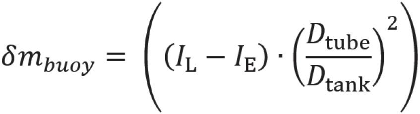
The experiment in the dose accuracy application note clearly shows that it makes sense not to neglect the displacement of the cannula in order to generate reproducible and valid measured values.
View the dose accuracy application note, here.
In the previous sections, various parameters were considered in detail, including temperature, weighing drift, electrostatics, cannula displacement, humidity and measurement interval (with an interval between readings of 30 seconds according to IEC 60601-2-24 and 10 seconds according to AAMI TIR-101).
B. Braun Melsungen provided an overview of the influence of various parameters on the different test characteristics, such as:
• Flow rate (< 1 mL/h)
• Flow rate (> 10 mL/h)
• Start-up curve
• Long-term measurement (> 6 h)1
• Mean percentage error (A).1
The combination of a particularly high resolution (up to 1 μg) together with a high maximum capacity and the monolithic weighing system make the Cubis® II balances the ideal test equipment for determining the dosing rates in accordance with IEC 60601-2-24 and TIR 101, in addition to numerous important advantages, such as the built-in ioniser and the electrically conductive draft shield.
With the help of B. Braun Melsungen’s measurement results, it was possible to show that influencing factors such as temperature and relative humidity have a marginal effect on the result of the dosing
rate. In addition, a high-precision test setup (Figure 5) could be used to determine that the Cubis® II semi-microbalances meet the quality requirements of IEC 60601-2-24 and ISO 7886-2.
The collection of data helped to optimise the Cubis® II balances for this application in order to generate fast and reliable measured values with this dynamic weighing value change. As a result of the experience gained in this application, Sartorius is able to respond quickly and competently to the challenges of infusion and insulin pump manufacturers. This helps to make the testing of dosing pumps more reliable and safer – simplifying progress.
Sartorius empowers scientists and engineers to simplify and accelerate progress in life sciences and bioprocessing, enabling the development of new and better therapies and more affordable medicine. The Lab Products & Services Division offers laboratories in the pharmaceutical and medical device industries, as well as at
academic research institutes, innovative solutions for bioanalytics, in addition to premium laboratory products, consumables and services. Sartorius is among the market leaders in laboratory balances, pipettes and lab consumables.
1. “Challenges in Testing the Dose Accuracy of Medical Infusion Pumps”. Application Note, Sartorius, Apr 2024.
Lucas Foerster is an experienced Product Manager spearheading lab weighing applications at Sartorius’s headquarters in Germany. With a master’s degree in Chemistry and extensive industrial experience, he expertly identifies applicationspecific solutions and advances automated weighing methodologies. Since 2022, Mr Foerster has been instrumental in defining and implementing product strategies, road maps and specifications, ensuring Sartorius remains at the forefront of innovation in its field. His passion for precision and dedication to enhancing operational efficiency underscore his commitment to excellence in every project he undertakes.
Dieter Peissig has more than 37 years of experience at B.Braun Melsungen, specialising in the development of infusion pumps. He serves as a specialist in infusion pump measurements within the framework of standards such as IEC 60601-2-24 and ISO 7886-2, actively participating in standardisation working groups. Mr Peissig’s responsibilities include conducting qualification measurements of infusion pumps using compatible disposable items for volumetric and syringe pumps, as well as providing consultative support as an internal consultant during challenging therapy situations in clinical settings.

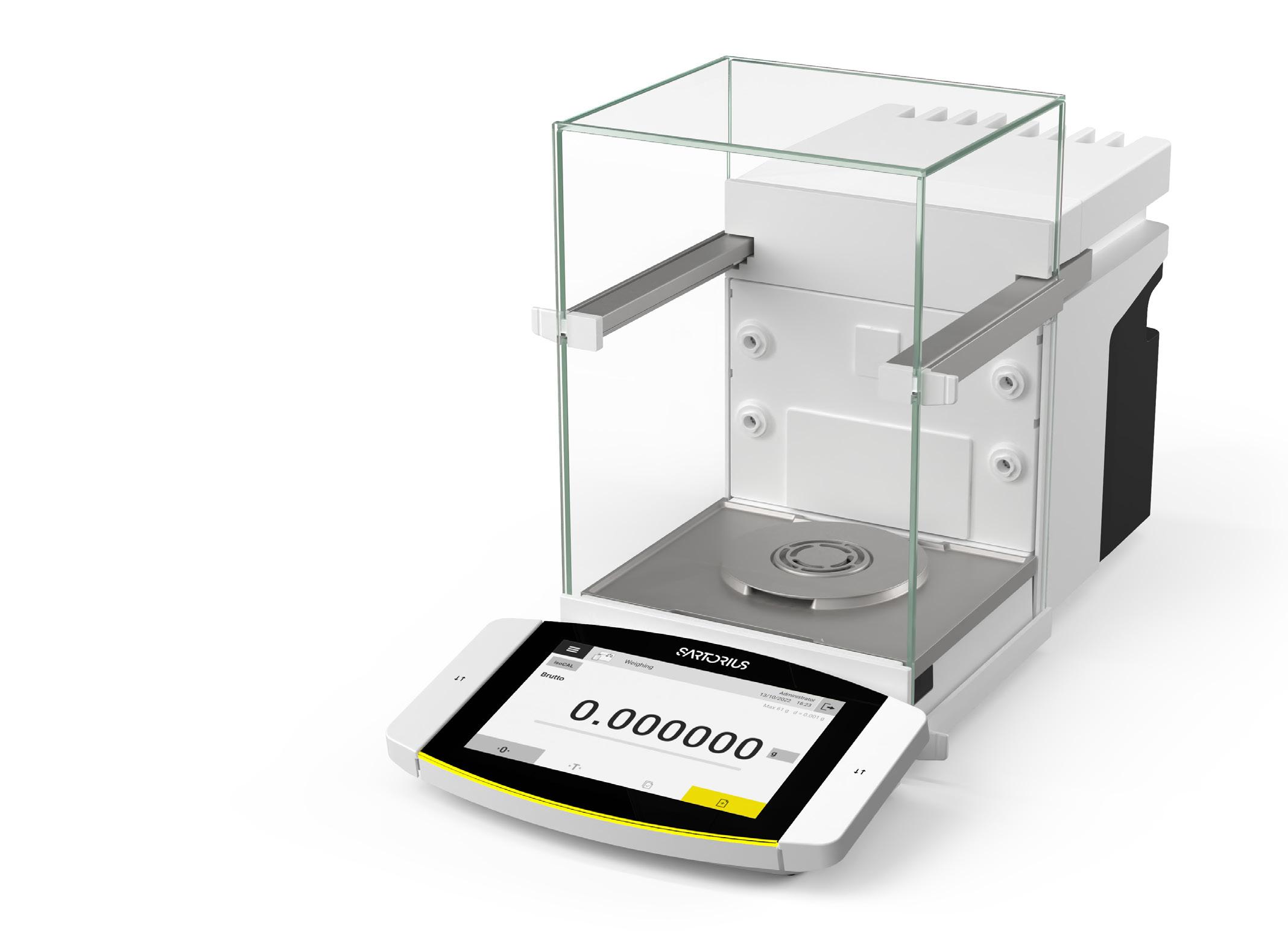
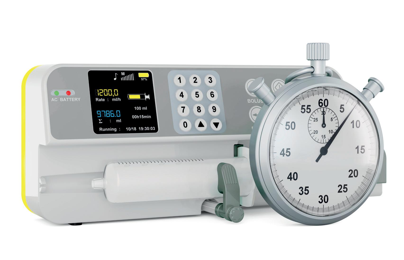
Be equipped with trustworthy data to uphold the integrity of medical infusion pumps throughout their lifecycle with:
Precision Testing: Ultra-High Resolution Cubis® II balances for accurate flow rate and dose assessment
Regulatory Compliance: Adherence to AAMI TIR 101, and IEC 60601-2-24
Innovative Technology: Monolithic weighing system to ensure minimal balance drift for longer testing periods
Discover the Sartorius difference in ensuring the reliability and integrity of infusion pumps, where every microliter counts.

www.sartorius.com
In this article, Olivia Houselander, Business Development Manager at Owen Mumford, outlines some of the challenges of developing drug delivery devices for the Japanese market and shares details of the company’s latest two products to gain approval in Japan.
It is no secret that breaking into new markets is a challenge within the drug delivery device industry. Nevertheless, that does not mean that device manufacturers should fail to make the effort, even if a market’s regulatory regime is tough. Japan, for example, is widely recognised as one of the most stringent markets for certification, where devices are regulated by the Pharmaceutical and Medical Device Agency under the Pharmaceutical and Medical Devices Act.1–6
Owen Mumford Pharmaceutical Services has been working in the Japanese market for over 25 years and has a proud history of developing combination products within it with its partners (Figure 1). While it was hard work to gain the first product certifications, the results have been more than worth the initial effort.

Olivia Houselander
Business Development Manager E: olivia.houselander@ owenmumford.com
Owen Mumford Ltd
Brook Hill, Woodstock, Oxfordshire, OX20 1TU United Kingdom
www.ompharmaservices.com

“Despite being home to numerous multinational medical device corporations, a significant proportion of Japanese medical devices come from foreign manufacturers.”
Despite being home to numerous multinational medical device corporations, a significant proportion of Japanese medical devices come from foreign manufacturers, with the country importing approximately 35% of its medical devices.7 There is a great deal of opportunity; an ageing population has created one of the largest medical device markets in the world, with it being estimated to reach over US$29 billion (£23.2 billion) in 2024.8 As a result, many suppliers are prepared to accept the potential length of time to market and the regulatory costs associated with the Japanese market, despite the challenges.
The product registration process has become more friendly to foreign manufacturers since
changes to its regulations in 2014, with new registration pathways for manufacturers and expanded third-party certification options – but a number of challenges still remain.9 The EU’s CE mark and US FDA approval are not accepted as equivalent to Japanese certification – although having them certainly speeds up device registration. Foreign manufacturers seeking medical device registration in Japan can look to work alongside a third-party “Designated Marketing Authorisation Holder” to help them register in Japan and liaise with the regulatory authorities. This is particularly useful for companies that do not have ready access to Japanese speakers within their teams, as it is necessary to submit all the required regulatory information in Japanese – another barrier to entering the market.
For medical device registration in Japan, applicants must submit a comprehensive dossier detailing device safety, performance and manufacturing quality control systems.10 Once this has been navigated successfully, stringent quality control measures are implemented. These measures ensure continued compliance with the initial standards, safeguarding the quality of devices throughout their lifecycle. Japan’s robust post-market surveillance system monitors any adverse events caused by devices and takes rapid action if safety concerns arise.10 Once approved, device registrations do not expire, but quality management system certificates must be renewed every five years.
Owen Mumford Pharmaceutical Services has a long track record of navigating the Japanese market, with several successful partnerships over the last 25 years. Most recently, the company has launched two combination products onto the market.


The UniSafe® safety syringe was launched with Owen Mumford Pharmaceutical Services’ exclusive distribution partner and its commercial alliance in Japan. The device enables the safe injection of a biosimilar used with cancer medicines. It is Japan’s first long-acting biosimilar for this application and can be administered once per chemotherapy cycle, starting the day after treatment is completed.
UniSafe is a springless, passive safety device for 1 mL prefilled syringes, designed to overcome some of the challenges of traditional spring-based safety systems. Its key design elements prioritise reliability and ease of use. The absence of a spring means that UniSafe prevents accidental activation before injection. The secure plunger mechanism helps to prevent the chances of the product being reused or accidental spillage before a full dosage is administered. The design is critical for preventing needlestick injuries, with the passive safety mechanism ensuring that the device is safe as soon as the plunger is fully depressed. With an estimated 525,000 cases of needlestick injuries in Japanese hospitals annually, devices such as UniSafe are key to improving safety within the industry.11
Owen Mumford Pharmaceutical Services has also been working alongside a Japanese pharmaceutical company to develop its product, approved to deliver a novel drug for rheumatoid arthritis (RA). The autoinjector is a bespoke, single use disposable autoinjector, designed and manufactured by Owen Mumford Pharmaceutical Services. Estimates vary on the number of sufferers of RA in Japan, but most studies put the number at around 0.75%–1% of the population, meaning a total of between 800,000 and 1 million patients.12,13
The autoinjector’s key features prioritise usability and patient safety. The device includes an easy-grip cap and body, which are exceptionally helpful for RA patients who are self-administering treatments and may have reduced grip and dexterity. The two-step injection process is one fewer than many autoinjectors on the market; Patients only need to remove the cap and fully depress the injector onto the injection site to undertake the injection, with no need to press a button to begin the procedure.
Owen Mumford Pharmaceutical Services was responsible for managing the entire development project, using its expertise to conduct multiple human factors studies to validate the usability of the device and scale up manufacture. This partnership dates back to 2019, and Owen Mumford Pharmaceutical Services is also working alongside partners to develop replica training injectors.
There are clearly distinct challenges in trying to get a drug delivery device to market in Japan as a foreign manufacturer. Not only must companies contend with some of the world’s most stringent regulations, but all documentation must be submitted in Japanese. Yet, the market size and propensity for importing medical devices means that there are significant opportunities for those willing to tackle the regulatory challenges and potential length of time to market.
Owen Mumford is a major healthcare company and device manufacturer that commercialises pioneering medical products, both under its own brand and as custom device solutions for the world’s major pharmaceutical and diagnostic companies. Owen Mumford’s goal is to enhance access to diagnostics, encourage adherence to treatment and reduce healthcare costs, making a world of difference to a world of people.
1. “Medical Device Registration and Approval in Japan”. Emergo, accessed Apr 2024.
2. “Market Access of Medical Devices in Japan”. Johner Institute, May 12, 2020.
3. “Gain market access in Japan. Pharmaceutical and Medical Device Act (PMD Act) Regulation”. BSI, accessed Apr 2024.
4. Hage J, “The most challenging countries for medical device commercialization – Thoughts?”. Medical Devices Group, May 2013.
5. “Mastering Japan’s Medical Device Approval Process: A Step-by-Step Guide”. Pacific Bridge Medical, Jun 8, 2023.
6. “The Role of IOR & EOR Services in Optimizing Clinical Trials in Japan”. Credevo, accessed Apr 2024.
7. “PMDA Japan Medical Device Registration”. Pure Global, accessed Apr 2024.
8. “Japan - Country Commercial Guide”. International Trade Administration Jan 2, 2024.
9. “Major Changes to Medical Device Registration Process in Japan”. Regulatory Focus, Nov 11, 2014.
10. “Japan vs. EU and US: Comparing Medical Device Regulatory Frameworks.” Pacific Bridge Medical, Jun 8, 2023.
11. Kunishima H et al, “Estimating the national cost burden of in-hospital needlestick injuries among healthcare workers in Japan”. PLoS One, 2019, Vol 14(11), Article e0224142.
12. Yamanaka H et al, “Estimates of the prevalence of and current treatment practices for rheumatoid arthritis in Japan using reimbursement data from health insurance societies and the IORRA cohort (I)”. Mod Rheumatol, 2014, Vol 24(1), pp 33–40.
13. Kojima M et al, “Epidemiological characteristics of rheumatoid arthritis in Japan: Prevalence estimates using a nationwide population-based questionnaire survey”. Mod Rheumatol, 2020, Vol 30(6), pp 941–947.

Olivia Houselander joined Owen Mumford as a Product Manager in 2008 and currently serves as an accomplished Business Development Manager in the Pharmaceutical Services division. In this role, she applies her extensive experience in medical devices, marketing strategy and product launch and development to support continued business growth and create innovative product launches, making her an asset in the dynamic healthcare landscape.
Your fill volume may change, with Aidaptus® auto-adjust plunger technology your auto-injector doesn’t need to
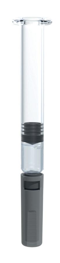
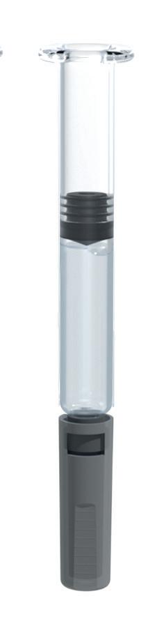
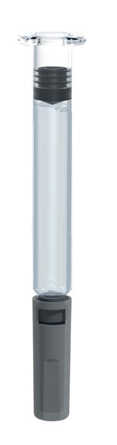
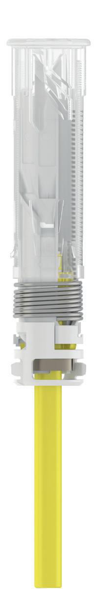
Accommodates both 1mL and 2.25mL glass syringes in the same device
See our auto-adjust plunger technology in action
Find out more by scanning the QR code or visiting ompharmaservices.com/odd-june2024
*In addition to an air bubble and overfill
Aidaptus® is a registered trademark of Owen Mumford Ltd, ©️2024
OMPS/odd/ad/ob/0624/7
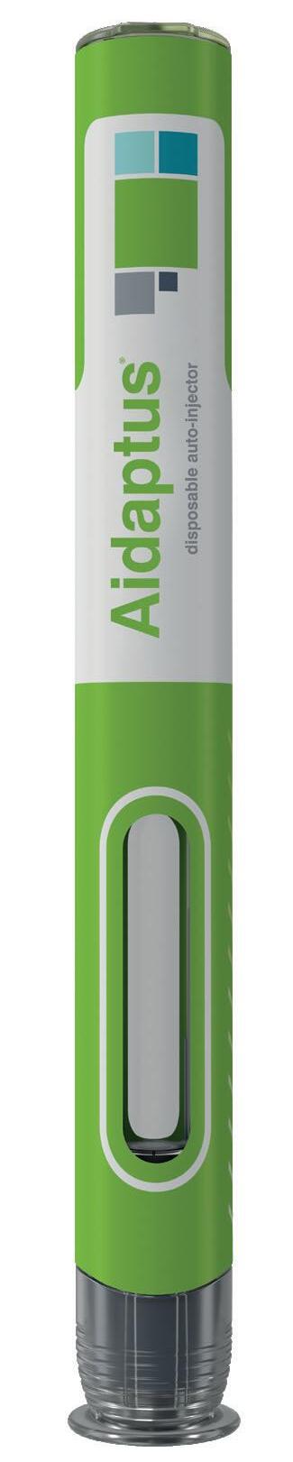
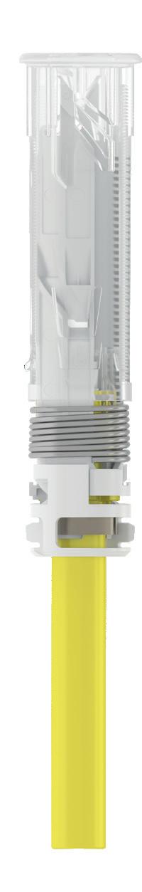
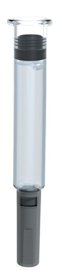
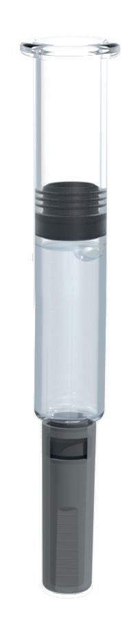
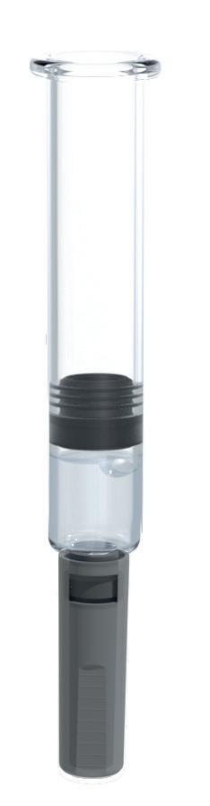
Now in collaboration with
In this article, Masashi Miura, Researcher, and Tomohiro Suzuki, Associate General Manager, both at Mitsubishi Gas Chemical, discuss the beneficial features of the OXYCAPT™ multilayer vial for biologics and gene and cell therapies, sharing recent study results highlighting OXYCAPT’s performance at -80°C under dry ice conditions and its high carbon dioxide barrier compared with standard cyclo-olefin polymer.
OXYCAPT OVERVIEW
OXYCAPT™ is a multilayer plastic vial and syringe developed by Mitsubishi Gas Chemical (MGC), offering a number of advantageous qualities as a primary drug container, including:
• Excellent oxygen and ultraviolet (UV) light barrier
• Strong water vapour barrier
• Very low extractables
• High pH stability
• Low protein adsorption and aggregation
• High transparency
• High break resistance
• Easy disposability
• Lightweight material.
MGC continuously conducts studies to confirm these properties. The latest results of these will be shared in the later part of the article. Before that, the first half of this article will provide an overview of the OXYCAPT multilayer plastic vial (Figure 1). The material consists of three layers – the drug contact layer and the outer layer are made of cyclo-olefin polymer (COP) and the oxygen barrier layer is made of MGC’s novel polyester (Figure 2).
MGC recently obtained a report on the environmental impact of glass and plastic containers for medical use from a Japanese research company. The report shows that plastic containers for medical use are much more environmentally friendly compared with glass containers.


Masashi Miura
Researcher
T: +81 463 21 8627
E: masashi-miura@mgc.co.jp

Tomohiro Suzuki
Associate General Manager
T: +81 332 83 4913
E: tomohiro-suzuki@mgc.co.jp
Mitsubishi Gas Chemical Company, Inc
Mitsubishi Building 5-2 Marunouchi 2
Chiyoda-ku
Tokyo 100-8324
Japan
www.mgc.co.jp/eng
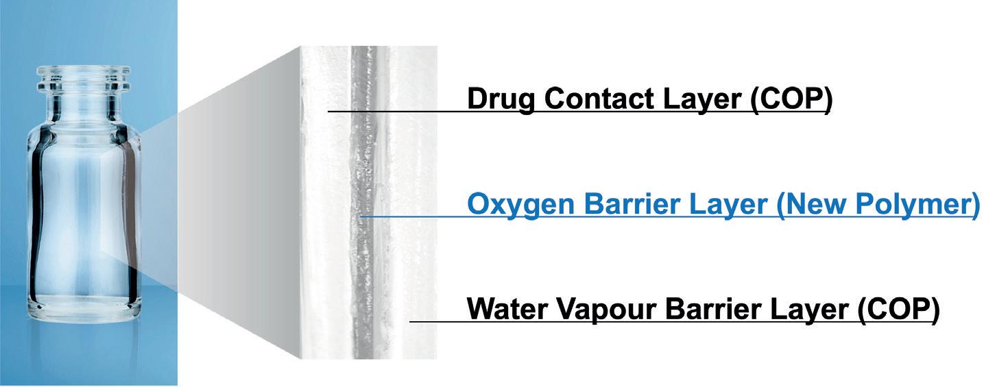
“The oxygen barrier of an OXYCAPT vial is about 20 times better than that of a COP monolayer vial.”
For example, the carbon footprint, nitrogen oxides emissions, sulfur oxides emissions and water consumption associated with plastic containers for medical use are several times smaller than those of their glass equivalents.
OXYCAPT provides an excellent oxygen barrier. For example, the oxygen barrier of an OXYCAPT vial is about 20 times better than that of a COP monolayer vial. Furthermore, OXYCAPT provides an excellent UV barrier. While about 70% of 300 nm UV light transmits through glass and COP, only 1.7% transmits through OXYCAPT. MGC has confirmed that this feature contributes to the stability of biologics.
While OXYCAPT cannot reach the performance of glass with respect to acting as a water vapour barrier, its properties are similar to those of COP, which has been used for injectable drugs for a long time. This means that OXYCAPT easily meets the requirements of a water vapour barrier set out by the ICH guidelines.
Studies have shown an extremely low level of extractables from OXYCAPT. One study was conducted to confirm the levels of volatile, semi-volatile and non-volatile impurities from OXYCAPT. Water and four solutions (50% ethanol, sodium chloride, sodium hydroxide and phosphoric acid) were selected, and impurities were measured by gas chromatography mass spectrometry (GC-MS) and liquid chromatographyUV spectroscopy-mass spectrometry (LC-UV-MS) after 70 days at 40°C. Compared with the control, impurities were not detected in the OXYCAPT containers. A second study confirmed
that inorganic extractables levels from OXYCAPT were similar to those from COP, which is well known for being an extremely pure polymer with a better extractables profile than Type 1 glass. Lower levels of inorganic extractables are known to contribute to better pH stability in drug products.
The OXYCAPT vial is produced by co-injection blow-moulding technology. MGC has also developed inspection methods for testing the oxygen barrier layer. All the containers are fully inspected by state-of-the-art inspection machinery.
MGC can offer bulk vials and readyto-use (RTU) vials, with its RTU products provided in standard nest and tub or tray formats. The nest and tub are mainly sterilised using gamma rays. There are 2, 6, 10 and 20 mL variants for vials. MGC is willing to provide samples for initial testing free of charge.
Each polymer meets the requirements of US Pharmacopeia (USP) regulations USP <661>, USP <87> and USP <88>, as well
as those of the European Pharmacopoeia, and has been filed in the US FDA’s drug master file (DMF). The vials are also compliant with each pharmacopoeia and have been filed in the DMF.
The primary target market for OXYCAPT is the therapeutic application of biologics. As mentioned in ICH Q5C (Stability of Biotechnological/Biological Products), oxidation is one of the causes of protein instability. As such, the oxygen and UV barrier properties of OXYCAPT will definitely contribute to the stability of biologics stored within. Furthermore, some drug developers have recently started evaluating the OXYCAPT vials for their gene and cell therapies; the RTU vial is sterilised by gamma radiation, making it ideal for protein-based drugs.
INTEGRITY AT -80°C
All pharmaceutical containers must maintain integrity against microbial contamination and have a gas barrier when a drug is sensitive to oxygen or carbon dioxide (CO2). Figure 3 shows a typical scheme of storage and transportation for gene therapy. During storage and transportation, packages, including vials, are exposed to temperatures of around -80°C in a deep freezer or dry ice, which is a potential risk to container closure integrity (CCI) due to differences in the coefficient of thermal expansion (CTE) of the vial and rubber closure materials.
The CCI of Type I glass vials is particularly at risk from very low temperatures compared with plastic vials because the CTE of typical Type I glass is a factor of 10 smaller than that of rubber, including a halogenated butyl rubber. On the other hand, standard plastic vials have a potential risk of CO2 transmission
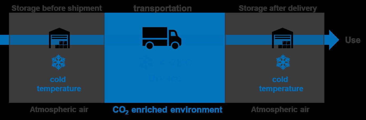

when in storage with dry ice. Based on MGC’s calculation by measurement of the transmission rate of CO2 through a polymer film, OXYCAPT has a CO2 barrier more than 20 times better than comparable COP monolayer vials. This means that the OXYCAPT vial has the potential to significantly contribute to protecting drugs, including biologics and gene and cell therapies, when they are in transport with dry ice.
To examine this potential benefit further, MGC performed a CCI test with dry ice. Table 1 shows the test sample combinations of OXYCAPT vial and rubber closures. Rubber closure 1 is a typical closure made of bromo butyl rubber with a glass transition temperature of -65°C. MGC also prepared press-on-cap closures and OXYCAPT’s positive control with a fine hole of a 5 µm nominal diameter.
Figure 4 shows the test procedure, which includes storage in a deep freezer and an insulation box with dry ice. First, all the vials, closures and aluminium seals were inserted into a chamber where the air was replaced with nitrogen, then they were assembled by hand in the chamber. After preparing the samples, MGC measured the partial pressure of CO2 in the vials’ headspace for all the samples (T0). The samples were then stored in a deep freezer at -80°C for seven days. After storage in the freezer, the CO2 pressure of the headspace was measured (T1). Next, the remaining samples were immediately inserted into an insulation box that was filled with 30 kg of dry ice, as shown in Figure 5. After storage in the CO2-enriched environment, CO2 pressure in the headspace was measured (T2).
Headspace pressure of CO2 was measured with an FMS-Carbon Dioxide, manufactured by LIGHTHOUSE Instruments (VA, US). The instrument is based on frequency modulation spectroscopy (FMS), which is a nondestructive method. Table 2 shows the sample number for each measurement time
“Based
on MGC’s calculation by measurement of the transmission rate of CO2 through a polymer film, OXYCAPT has a CO2 barrier more than 20 times better than comparable COP monolayer vials.”
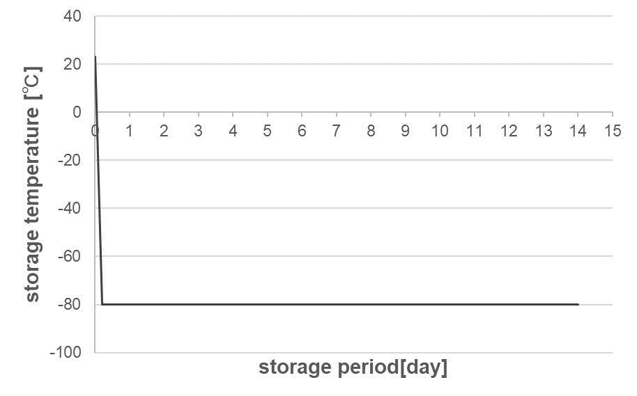

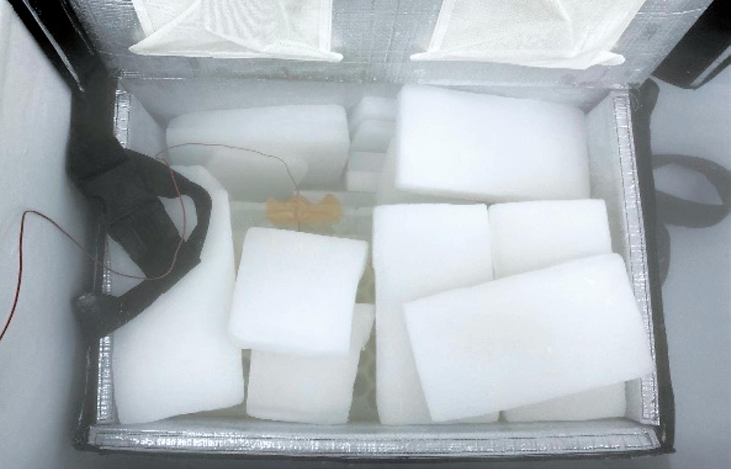
point. The measured vials were disposed of after the measurements at T1 and the remaining ones were measured at T2
At temperatures lower than -65°C, bromo butyl rubber loses its elastic properties, which may lead to loss of airtightness at the interface between vial and rubber closure. Therefore, maintaining a temperature inside the insulation box of under -65°C is crucial for measuring the leakage precisely in this test. Figure 6 shows a temperature log inside the insulation box during the test, which was kept below -70°C for seven days.
Figure 7 shows the results of headspace CO2 pressure for Entries 1, 2 and 1’. Regarding OXYCAPT positive control of Entry 1’, the mean value of CO2 pressure was 183 Torr at T2 under a CO2-enriched environment. However, there was no CO2 ingress at T1, as the initial seven-day storage was conducted under atmospheric conditions without dry ice. On the other hand, CO2 ingress was not observed in
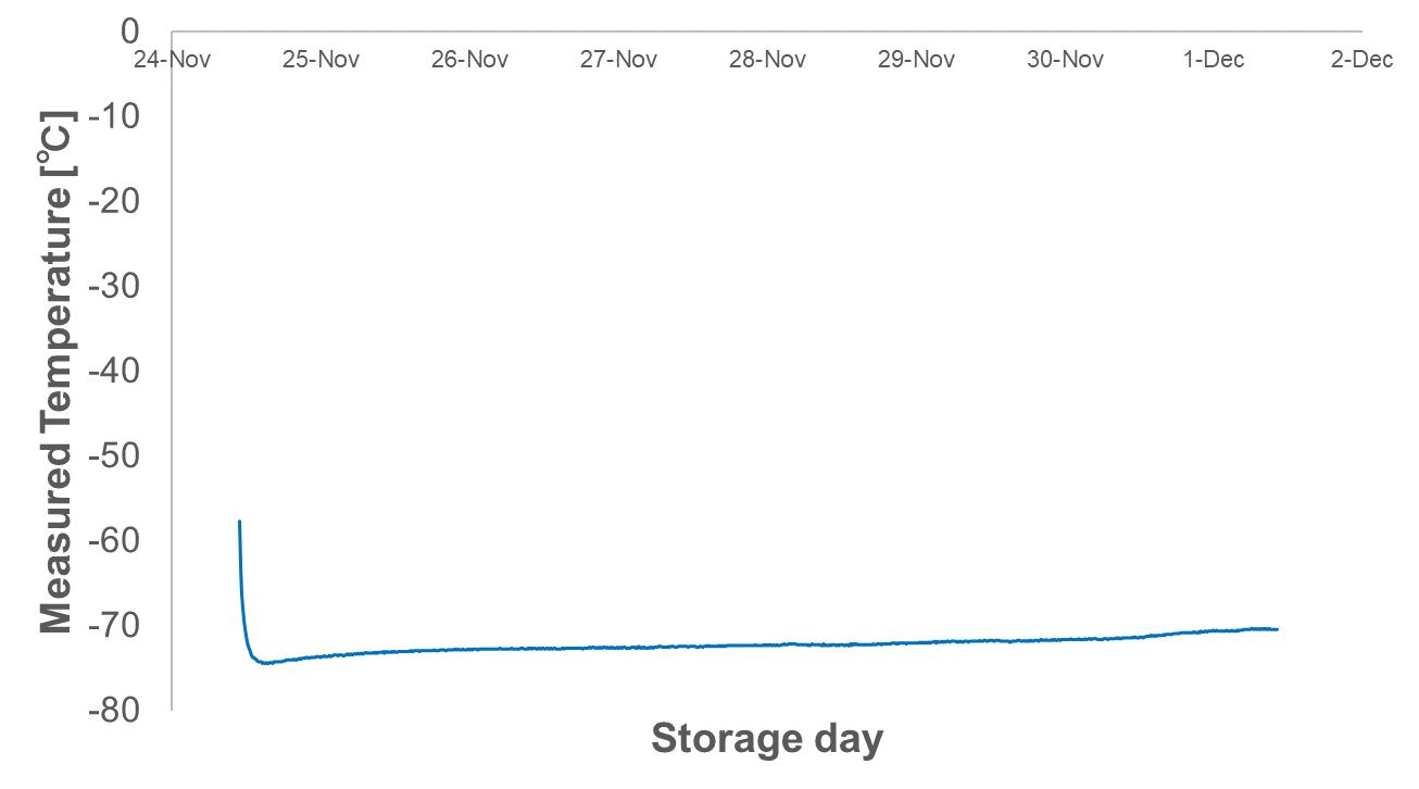
either combination of OXYCAPT and the two types of closure (Entry 1 and Entry 2), even at T2. This study demonstrated that OXYCAPT has an excellent CCI under a CO2-enriched environment for seven days.
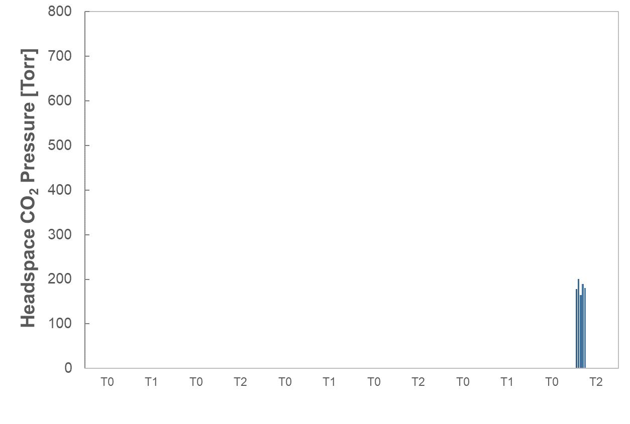
There are several factors that can affect CCI for a combination of vials and closures, including capping force and type of closure, among others. In addition, CO2 transmission is potentially observed in longterm storage with dry ice and an increase in temperature during storage. MGC intends to devise and perform additional CCI tests to clarify the efficiency of OXYCAPT vials compared with other plastic and glass vials. Furthermore, MGC is also planning to conduct similar studies at -180°C to confirm the effectiveness for gene and cell therapies.
CO2 molecules can permeate through polymers and get into a vial’s headspace, affecting drug stability. As the rate of CO2 transmission is different between polymer materials, MGC performed some related studies using OXYCAPT and COP vials. OXYCAPT and commercially available COP 10R vials were prepared with bromo butyl rubber (BBR) and aluminium seal closures. Firstly, all the vials and BBR and aluminium seals were placed in a nitrogen chamber for a couple of days. Secondly, the vials were sealed with the closures using
a hand-crimper in a nitrogen chamber. Thirdly, these vials, filled with nitrogen gas, were placed in a box filled with CO2 and stored at 23°C.
Figure 8 shows the results of headspace CO2 partial pressure of OXYCAPT and COP vials. Although the CO2 partial pressure of COP vials immediately rose, reaching around 700 torr in 60 days, the OXYCAPT vials were able to keep CO2 partial pressure to very low levels.
MGC also calculated the CO2 transmission rate of OXYCAPT and COP vials by using the test results of CO2 partial pressure. While only 0.018 cm3 of carbon dioxide transmitted through OXYCAPT 10R vials per day at 23°C, 0.423 cm3 transmitted through 10R COP vials (Figure 9). This result demonstrates that the CO2 barrier of OXYCAPT is more than 20 times better than that of standard COP.
These latest results have contributed to the ongoing studies verifying OXYCAPT’s superior properties for biologics and gene and cell therapies. In addition to the advantages of COP, such as a strong water vapour barrier, high break resistance, very low extractables and low protein adsorption, OXYCAPT also provides strong oxygen and UV light barriers. In particular, the excellent CO2 barrier of OXYCAPT is very useful for the stability of gene and cell therapies stored with dry ice. MGC believes that OXYCAPT offers a multitude of benefits to the rapidly growing field of biologics and gene and cell therapies.
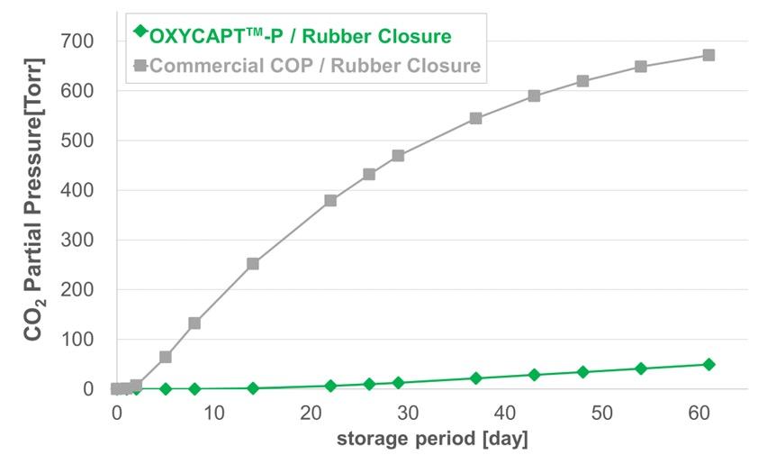
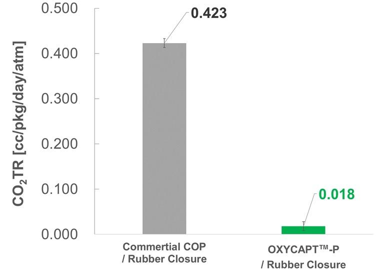
Masashi Miura is a Researcher at Mitsubishi Gas Chemical’s Hiratsuka Research Laboratory. He gained a diploma in Science in 2020 and a master’s degree in 2022 from Osaka University (Japan). At university, he majored in Applied Chemistry and studied crystalline porous materials. He has worked for Mitsubishi Gas Chemical since April 2022, joining a development team for multilayer plastic vials and syringes for biologics in May 2022.
Tomohiro Suzuki graduated from Waseda University (Japan) in 1997 and joined MGC in 1998. He belonged to the Oxygen Absorbers Division until 2011, after which he was transferred to the Advanced Business Development Division in 2012 to be a member of the OXYCAPT development team. Since then, he has been in charge of marketing for the OXYCAPT vial and syringe. His current position is Associate General Manager.
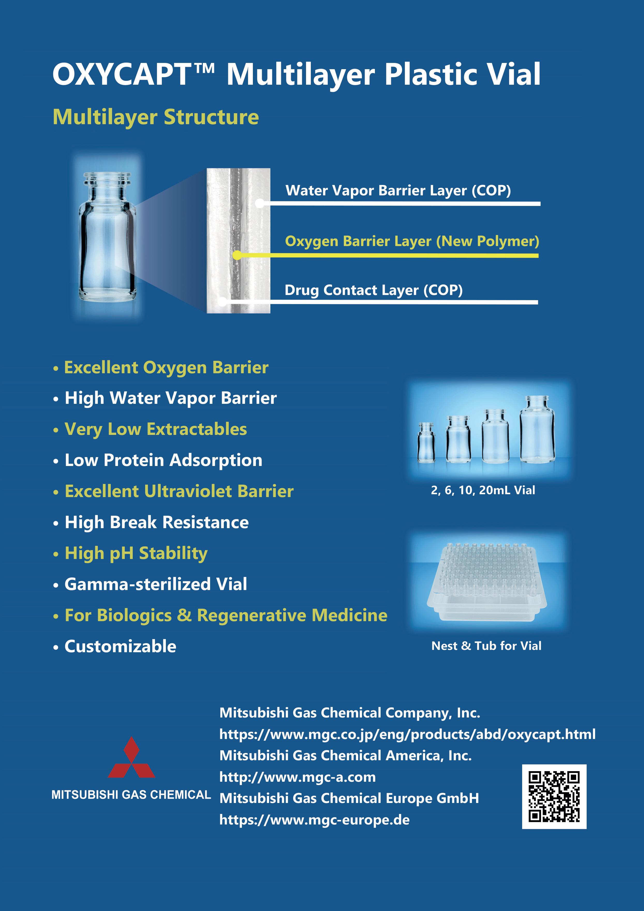
Here, Laure-Hélène Guillemot, PhD, Technical Product Manager, Benjamin Brocco, PhD, Marketing Manager, Edouard Pagnoud, Product Line Manager, and Pascal Sircoulomb, Business Development Director, all at Aptar Pharma, discuss some of the key parameters to consider when choosing a vial stopper and present evaluation methods that were developed to test and demonstrate the compatibility of various stoppers with commonly used vial designs.
In both the creation of new pharmaceuticals and the repurposing of existing medications, the role of packaging is crucial and should not be overlooked. A thorough understanding of packaging materials and their compatibility is fundamental to ensuring that medications are kept in an environment that safeguards their quality until usage is required.
The primary container, being in direct contact with the medication, is pivotal in preserving a medication's quality from production, through packaging and distribution, to storage and eventually administration. Any issues with the primary container could lead to negative outcomes for patients – such issues not only have a profound human cost but could also lead to substantial financial losses for the manufacturer.
A critical aspect of the primary container’s role is to ensure the integrity of its closure throughout the medication's lifecycle. For injectable drugs, which commonly use glass vials as the primary container, achieving this integrity hinges on the perfect compatibility between the vial and its rubber stopper.
Despite the standardisation of vial sizes, as outlined in ISO8362-1 for those made from glass cane and ISO8362-4 for moulded glass vials, compatibility challenges can emerge. These challenges
“These challenges may manifest as difficulties in inserting stoppers, stoppers accidentally popping off prior to crimping or breaches in the CCI.”
may manifest as difficulties in inserting stoppers, stoppers accidentally popping off prior to crimping or breaches in the container closure integrity (CCI). Such issues not only complicate operational processes but may also pose a threat to patient safety.
To emphasise the importance of these risks, various vial neck designs have been created to specifically address pop-off issues – the European blow-back (EBB) and American blow-back (ABB) – that are derived from the standard non-blow-back (NBB) design. Choosing the appropriate combination of stopper and vial is therefore a crucial decision that influences both the packaging development and the efficiency of the drug fill/finish processes.
Aptar Pharma has honed its expertise over 50 years of collaborations with pharmaceutical and biotech companies,
Dr Laure-Hélène Guillemot
Technical Product Manager, Vial Containment Solutions
T: +33 6 3794 0140
E: laure-helene.guillemot@aptar.com
Dr Benjamin Brocco
Marketing Manager
T: +33 6 7404 8924
E: benjamin.brocco@aptar.com
Edouard Pagnoud
Product Line Manager, Vial Containment Solutions
T: +33 6 7018 5027
E: edouard.pagnoud@aptar.com
Pascal Sircoulomb
Business Development Director, Vial Containment Solutions
T: +33 6 8593 5292
E: pascal.sircoulomb@aptar.com
Aptar Pharma 10 Rue Louis Blériot 92500 Rueil-Malmaison
France
www.aptar.com/pharma
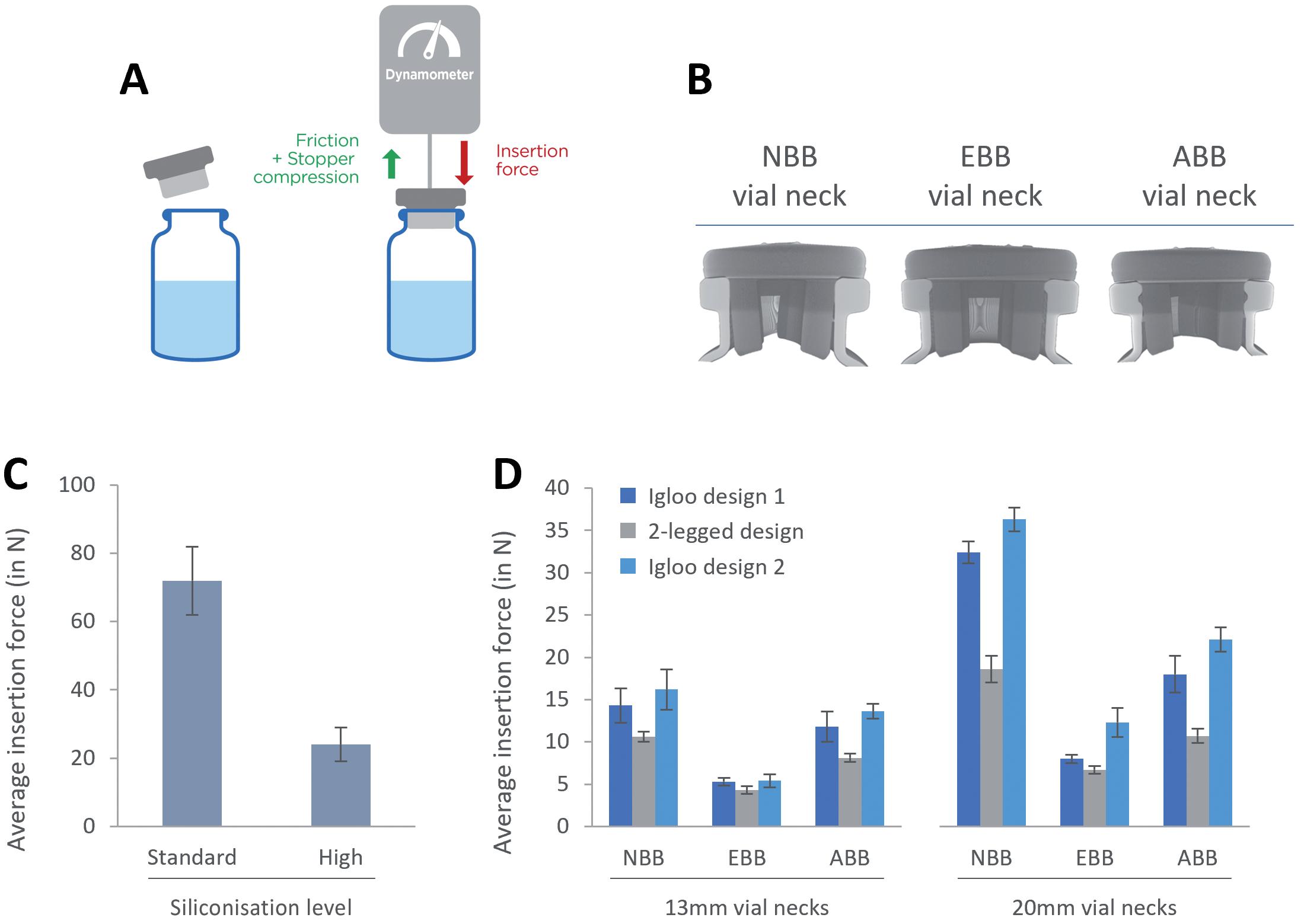
Figure 1: Evaluation of the insertion force with lyophilisation stoppers. A: Experimental set-up and representation of the forces that contribute to determining the insertion force. Stoppers are inserted at a constant speed of 100 m/min. B: X-ray tomography of an NBB stopper lyo two-legged design inserted in NBB, EBB and ABB vials. C: Evaluation of the impact of the siliconisation level on the insertion force. D: Evaluation of the insertion force for three different lyophilisation stopper designs with NBB, EBB and ABB vials.
addressing packaging challenges for vaccines, biotech drugs and small molecules. Aptar Pharma’s vial stoppers leverage pure elastomer formulations and are designed with a holistic understanding of all compatibility issues that may be encountered when choosing a vial or stopper system.
Controlling the force required to insert stoppers in a given vial can be key for ensuring operational efficiency and consistent performance on a filling line. This insertion force is influenced by several factors, such as the dimensions and designs of the stopper’s plug and the vial neck, the elastomer's hardness and the quantity and nature of lubricant used on the stopper. Optimising these parameters is key as a stopper that is too hard to insert may not be placed ideally on the vial, while a stopper that fits too loosely may accidentally fall off the vial, two situations that can put the integrity of the drug at risk.
“Optimising these parameters is key as a stopper that is too hard to insert may not be placed ideally on the vial, while a stopper that fits too loosely may accidentally fall off the vial, two situations that can put the integrity of the drug at risk.”
To test these parameters, Aptar Pharma experts use an evaluation method that relies on the use of a dynamometer mounted on a test bench that inserts a given stopper on a given vial at a rate of 100 mm/min (Figure 1A). In these results, Aptar focused on evaluating the impact of siliconisation on the insertion force and tested three different stopper designs on three different vial neck designs. X-ray tomography was also used to provide insights in justifying the variation of insertion forces observed (Figure 1B).
Figure 1C compares stoppers that have been lubricated with different quantities of silicone oil, which is added during the
drying step at Aptar Pharma. The data clearly show that the addition of extra silicone onto the stopper facilitates the insertion, reducing the insertion force by more than 60%.
Figure 1D shows the insertion force required to insert lyophilisation stoppers into various designs of 13 mm and 20 mm vials. When inserted into EBB vials, all three designs perform similarly. For both NBB and ABB vials, the two-legged design demonstrates a reduced insertion force compared with its igloo counterparts. To further understand these results, X-ray tomography was performed, allowing a clear view of how the stopper is inserted
in the vial neck. The position of the stopper in the vial neck seems to indicate that, with the EBB vial, the rubber is under less constraint, which could translate to lower insertion forces. For both the NBB and ABB vial designs, the legs of the stoppers are bent slightly inwards, indicating increased geometrical constraints, which could contribute to increasing insertion forces. In all three cases, the stoppers form a seamless seal with the vial’s flange and with the top of the neck.
These results demonstrate that the design of both the vial neck and the stopper can
affect the insertion force for a vial/stopper combination. Furthermore, lubrication, in the form of silicone oil, can help dramatically modulate the insertion forces of a stopper by decreasing friction.
When discussing the compatibility between a vial and a stopper, pop-off is one of the main issues that ought to be considered. “Pop-off” refers to the event when the vial stopper spontaneously dislodges itself from the vial neck in between the stoppering
event and crimping the vial. This not only disrupts the filling process but also results in the loss of medication.
After a stopper is fitted into the neck of a vial, various forces are at play to determine whether or not it stays in place. Inserting the stopper increases pressure in the vial's headspace, creating a force that could eject the stopper. Conversely, the friction between the rubber stopper and glass vial acts to keep the stopper secured. Therefore, the outcome – whether the stopper remains firmly seated or is forced out – depends on the design of the vial's
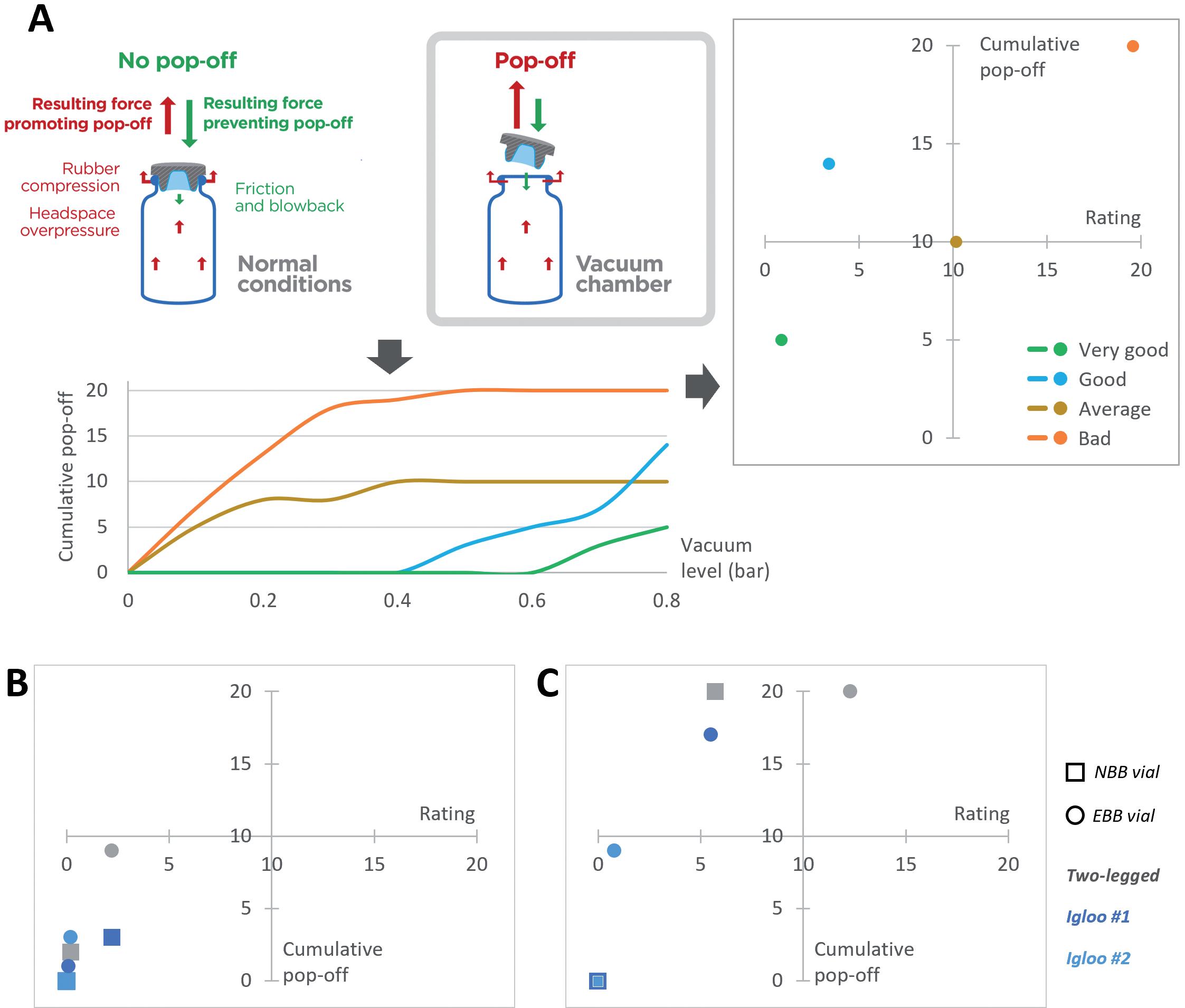
Figure 2: Evaluation of the risk of pop-off associated with various vial/stopper combinations. A: Representation of the experimental set-up and the forces at play. The curves represent the cumulative number of pop-off events with regards to the pressure gradient created in the vacuum chamber. Depending on the cumulative number of pop-off events observed and at which pressure they happen, a rating is calculated and plotted against the cumulative number of pop-off events. Representative cases were plotted to illustrate a bad, average, good and very good performance. B: Representation of performance of a two-legged, igloo #1 and igloo #2 designs for 13 mm stoppers with NBB and EBB vials. C: Representation of performance of a two-legged, igloo #1 and igloo #2 designs for 20 mm stoppers with NBB and EBB vials.

Big health challenges require transformative thinking. At Aptar Pharma, we’re transforming expectations of what an injectables partner can be.
To meet increasing demand and expectations for drug/container compatibility, we’re expanding our manufacturing footprint to deliver billions of additional injectable components each year, including 1 billion PremiumCoat® ETFE film-coated solutions. We’ve already implemented advanced robotics and added new clean rooms to enhance quality and derisk your sensitive drug development.
With our increased capacity and agility, together we can meet the world’s biggest health challenges, today and tomorrow. Join us.

Shaping the future of injectables, together visit www.aptar.com/pharmaceutical
“The outcome – whether the stopper remains firmly seated or is forced out – depends on the design of the vial's neck and the stopper, and how the rubber compresses against the glass.”
neck and the stopper, and how the rubber compresses against the glass. Insufficient forces holding the stopper, such as reduced friction due to excessive silicone lubrication, may lead to a pop-off.
To evaluate the risk of pop-off associated with a given vial/stopper combination, Aptar Pharma’s experts have developed a specific protocol. A vial is stoppered under atmospheric conditions then placed in a vacuum chamber. The pressure is gradually decreased to increase the pressure gradient between the inside of the vial and the vacuum chamber (Figure 2A), which helps trigger pop-off artificially.
The number of stoppers popping off, as well as the pressure difference at which they pop off, is key to properly evaluating the risk of pop-off. To assess this, Aptar Pharma calculates a rating using the integral cumulative pop-off versus the vacuum. To facilitate the visual interpretation, a matrix representation is used, the lower left quadrant representing the best performance while the top right represents suboptimal performances.
When analysing the results with 13 mm stoppers (Figure 2B), Aptar Pharma observed very strong performances overall, with all stoppers being in the lower left quadrant. The two-legged design stoppers were more likely to pop off than their counterparts, especially when combined with an EBB vial.
Figure 2C shows that the two igloo stoppers did not exhibit any pop-off when combined with an NBB vial. Some popoff occurred when combined with the EBB vial, but the low rating indicates that pop-off only happened at higher pressure differentials. The two-legged 20 mm vial stopper popped off more frequently, especially when combined with an EBB vial. However, it is important to note that no pop-off occurred at atmospheric pressure and that the first pop-off was observed at a pressure gradient of 0.3 bar.
When choosing a vial/stopper combination, the risk of pop-off needs to be carefully considered. In the case of lyophilisation stoppers, the data
demonstrate that the two-legged design is more likely to pop off than an igloo counterpart. This could be explained by the fact that, because the two legs are independent from each other, they are more susceptible to bending inward and may therefore apply less pressure on the neck off the vial, which may reduce friction.
Some manufacturers may choose twolegged designs to optimise the lyophilisation process, which can be a trade-off with the risk of pop-off when a pressure gradient builds up. However, it is important to note that this situation would only be encountered if a vial is overfilled, which cannot be the case for a lyophilised drug. Regardless of the vial design and the chosen stopper, under normal conditions, all lyophilisation stoppers are unlikely to pop off.
It is also important to emphasise the fact that the test method shown here represents an exaggeration of a worst-case scenario and that such strong pressure gradients are unlikely to happen in normal situations. None of the stoppers tested popped off with a pressure gradient below 0.3 bar.
These results demonstrate that the shape of the stoppers and the vial neck can affect the risk of pop-off. Other factors, such as the lubrication level of the stopper, may also impact the risk of pop-off and independent experiments demonstrated that reducing friction by increasing the quantity of silicone on the stoppers may lead to higher chances of pop-off (data not shown). Drug manufacturers must choose the right
“The capacity of a stopper to maintain CCI with a given vial will directly depend on its design, as CCI relies on the establishment of an airtight seal between the glass and the rubber.”
vial/stopper combination and manage the trade-off between reducing insertion force and reducing the risk of pop-off.
After being positioned within the vial's neck and secured with aluminium crimping, the stopper becomes crucial in maintaining the vial's CCI, blocking any ingress of air or germs from the external environment. The CCI is vital for the long-term preservation of the medication and avoiding contamination, thereby safeguarding patient safety. The capacity of a stopper to maintain CCI with a given vial will directly depend on its design, as CCI relies on the establishment of an airtight seal between the glass and the rubber. Storage in harsh conditions, such as deep-cold storage, and the crimping force used with the aluminium cap can also play a role, as discussed in a previous article.1
Until recently, probabilistic methods, as described in US Pharmacopeia <381>, were used. An example is methylene blue testing, where a vial is stoppered and crimped at atmospheric pressure and the system then immersed in a methylene blue solution and the pressure decreased, which would lead to a pressure gradient pulling air out of the system. The system is then brought back to ambient temperature, which leads to an ingress of methylene blue if the CCI fails, enabling visual identification.
With the implementation of USP <382> on December 1, 2025, the use of deterministic methods will become mandatory, one of which is headspace laser testing. In this test, a vial is stoppered under vacuum and stored at atmospheric pressure. A sharp increase of pressure inside the vial is indicative of CCI failure. In this second case study, featuring PremiumCoat® ETFE film-coated stoppers, this deterministic method was used.
It is important to note that blow-back vial designs were specifically designed to address pop-off related issues and not CCI issues. Therefore, when looking at the corresponding tomography pictures (Figure 3A), in every situation, the land seal is formed between the stopper’s plate and the vial’s flange, which is not affected by the vial or stopper designs. Another seal is formed between the stopper’s plug and the vial and, due to the elasticity of the rubber, it can be seen that the presence of the blow-back feature on the vial does not affect the formation of a tight seal at the top of the vial’s neck.
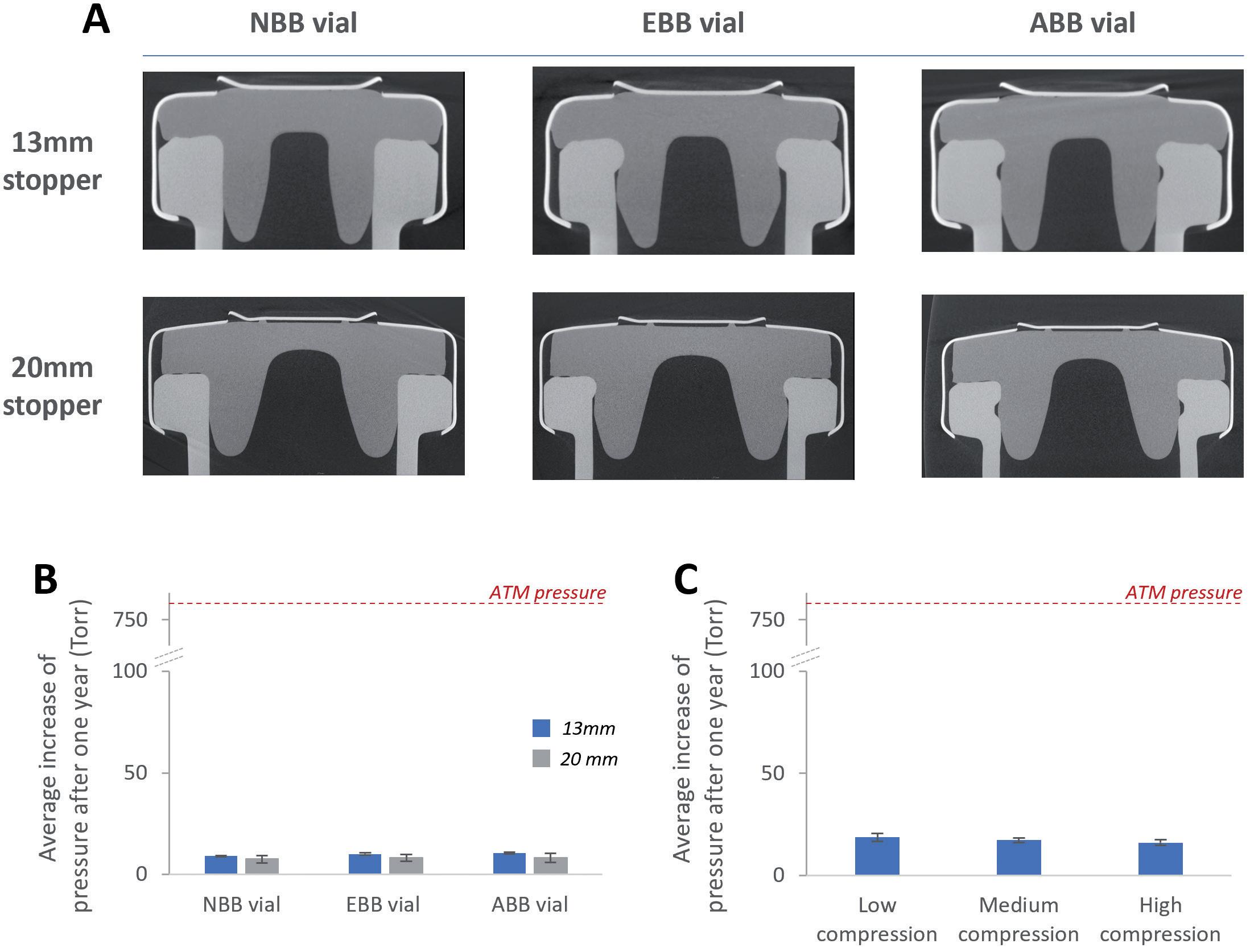
The tomography observations were confirmed by the use of the deterministic laser headspace analysis method. Aptar Pharma’s experts investigated whether the tested stopper could maintain CCI on NBB, EBB and ABB vials after having been crimped at low, medium or high compression. Regardless of the crimping force used, Figure 3B shows that the stoppers always maintained CCI after a period of one year, despite the fact that an NBB stopper was used with EBB and ABB vials. This confirmed that the seal formed between the vial and the stoppers was able to maintain CCI for the long term.
The crimping force used to secure stoppers in place could also play a role in ensuring long-term CCI, as a higher compression could promote the formation of a tighter land seal between the stopper and the vial’s flanges. However, it is important to note that applying excessive crimping force during the stoppering
process could lead to partial tearing of the rubber. Figure 3C shows that, regardless of the compression force used, the PremiumCoat® stopper tested could maintain CCI.
Vial and stopper compatibility is essential to ensure the safety of the drug and rapid time to market. The new USP <382> emphasises the responsibility of the drug manufacturer to demonstrate fitness for intended use for its primary packaging systems, instead of fully relying on the supplier. However, choosing the right partner can allow a pharma company to tap into its expertise, leverage existing data to derisk its choice and get to market faster.
Aptar Pharma has developed and tested a set of methods for evaluating the performance of its product range. Whether
it is uncoated stoppers used for liquid or lyophilised applications or PremiumCoat® vial stoppers, Aptar Pharma’s designs have been demonstrated to perform appropriately across a variety of situations with a variety of vial designs. This expertise and wealth of data has allowed Aptar Pharma to create comprehensive data packages for its PremiumCoat® stoppers, which cover relevant compatibility testing (CCI, pop-off, insertion force) and a complete extractables profile for regulatory filing and simulation studies for probable leachables. To complement Aptar Pharma’s injectables expertise, Gateway Analytical (PA, US) has developed a complete service offering to perform all the validation testing required for a customer’s drug filing. All tests are performed in cGMP certified labs and cover the complete range of what is required by regulatory bodies, including particle testing, extractables and leacheables and CCI.
For pharma customers worldwide, Aptar Pharma is the go-to drug delivery expert, from formulation to patient, providing innovative drug delivery systems, components and active material solutions across the widest range of delivery routes, including nasal, pulmonary, ophthalmic, dermal and injectables. Aptar Pharma Services provides early-stage to
commercialisation support to accelerate and de-risk the development journey. With a strong focus on innovation, it is leading the way in developing digital healthcare devices to help improve patient adherence and compliance. With a global manufacturing footprint of 15 manufacturing sites, Aptar Pharma provides security of supply and local support to customers. Aptar Pharma is part of AptarGroup, Inc.

Laure-Hélène Guillemot, PhD, is the Technical Product Manager for the Stoppers Franchise at Aptar Pharma’s Injectables division. Dr Guillemot holds an engineering degree from the Superior School of Chemistry Physics and Electronics (Lyon, France) and a PhD in Chemical Physics from CEA-Leti (Grenoble, France). Having worked for over six years in the construction products industry, she has developed a strong expertise in material chemistry and project management for product development. She joined Aptar Pharma in 2020.

Benjamin Brocco , PhD, is the Marketing Manager for Aptar Pharma’s Injectables division. He holds a PhD in Biophysics and is a graduate of Grenoble Ecole de Management (Grenoble, France). Previously, Dr Brocco worked at a world-leading drug delivery device company where he developed an in-depth understanding of injectable drug developers’ needs. He joined Aptar Pharma in 2020 to co-ordinate the company’s global marketing operation for the Injectables division and further develop Aptar Pharma’s leadership in scientific and technical communication within the drug delivery market.

1. Cordier S, Brocco B, Verger E, Clausse A, “Cold Storage and Container Closure Integrity –Demonstrated Performance of ETFE-Coated Components.” ONdrugDelivery, Issue 147 (May 2023), pp 6–11.

Edouard Pagnoud is the Product Line Manager for the Stoppers Franchise at Aptar Pharma’s Injectables division. As a graduate in Chemical Engineering from the Université Technologique de Compiègne (France), Mr Pagnoud has spent over 10 years in the cosmetic and pharmaceutical industry. Before joining Aptar Pharma in 2021, he occupied technical and industrial positions and developed strong expertise in product development and lifecycle management for high-value solutions. In his current position, Mr Pagnoud is responsible for the vials solutions platform and is committed to supporting customer development projects.

Pascal Sircoulomb is the Business Development Director for the Stoppers Franchise at Aptar Pharma’s Injectables division. He has over 35 years’ experience in the medtech and pharmaceutical industries, having held a variety of position in sales, marketing and business development at European and global levels. His experience covers medical devices, diagnostics devices and equipment and pharmaceutical packaging. In his current position, Mr Sircoulomb is responsible for business development activities for vials solutions and is dedicated to enabling customer projects as well as new drug development.
www.ondrugdelivery.com/participate
Here, Uwe Rothhaar, PhD, Director, Daniel Haines, PhD, Head of Pharma Services North America, Matthias Bicker, PhD, Scientific Advisor, and Thomas Schmidt, Study Director, Analytical Services, all at SCHOTT Pharma Services, discuss the analytical techniques used to identify the material components and composition of primary containers for injectable drug products.
Drug container closure and delivery systems are constructed from components made from various material classes, including glass, rubber and plastic, in combination with several other aspects, such as coatings, treatments and process refinements, that provide special properties and functional performances. A key responsibility of pharmaceutical companies is to ensure that the actual quality of packaging components supplied by component manufacturers meets compendial requirements and matches the agreed upon specifications. Especially critical are the materials and surfaces in direct contact with the drug product, which can have a large influence on its stability and shelf life. Therefore, the characterisation of packaging components with respect to the compositions of the used materials, coatings and/or refinement processes is an important factor in ensuring the quality and performance of the complete pharmaceutical packaging system.
SCHOTT Pharma Services provides packaging material identification studies (PMIS) that support the pharmaceutical industry in confirming material specifications from component vendors, via either lot-to-lot or yearly supplier verification, or in elucidating the component material
“A key responsibility of
pharmaceutical companies is to ensure that the actual quality of packaging components supplied by component manufacturers meets compendial requirements and matches the agreed upon specifications.”
and surface compositions of already marketed products. In addition, these studies can support the troubleshooting of drug container compatibility issues such as protein adsorption or aggregation, pH shift, glass delamination, leaching of elemental impurities and other drug stability issues that may arise from the use of different primary packaging components and materials.
A typical set of aspects considered in a PMIS is shown in Figure 1. In these studies, a set of different analytical techniques is
Dr Uwe Rothhaar Director E: uwe.rothhaar@schott.com
Dr Daniel Haines
Head of Pharma Services North America E: daniel.haines@us.schott.com
Dr Matthias Bicker
Scientific Advisor E: matthias.bicker@schott.com
Thomas Schmidt
Study Director, Analytical Services E: thomas3.schmidt@schott.com
SCHOTT Pharma AG & Co KGaA Hattenbergstraße 10 55122 Mainz Germany
www.schott-pharma.com
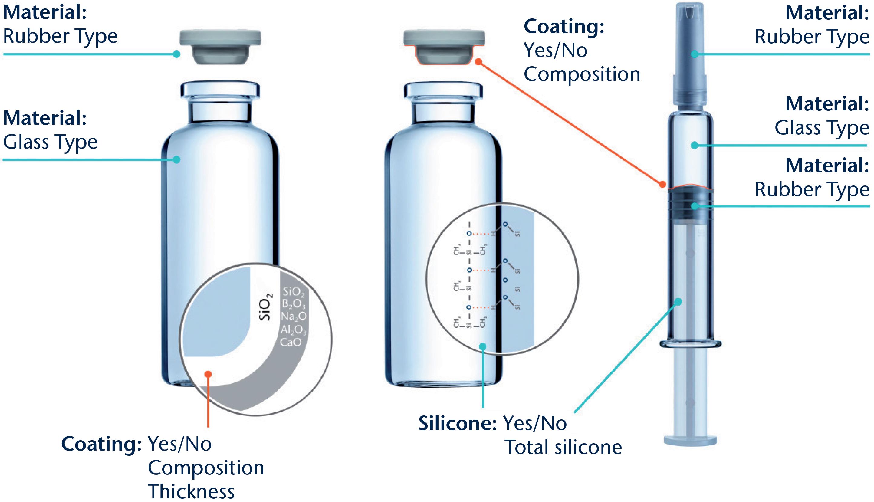
used to gain insights into the different base materials used and to reveal surface functionalisation by, for example, siliconisation, coatings, ion-exchange or de-alkalisation. The results are then compared with in-house databases of published compositions and reference materials. Combining this set-up with extensive expertise in drug packaging design, development and characterisation enables the identification of properties specific to the chosen containment solution design.
Glass is by far the most common container material used where there is direct contact with parenteral drug products. Up until September 30, 2023, the US Pharmacopeia (USP) <660> and European Pharmacopeia (Ph Eur) 3.2.1. defined pharmaceutical glass as either a borosilicate (neutral) or a sodalime-silica type. Based on the results of tests described in those monographs, the glass containers are classified as Type I, made of borosilicate glass; Type II, made of soda-lime-silicate with a surface treatment (de-alkalisation); or Type III, consisting of soda-lime-silicate without treatment. The Type I and II containers feature a high hydrolytic resistance compared with those made of Type III glass, which only exhibit moderate hydrolytic resistance. One essential internationally recognised
“There
is a wide composition range of clear and coloured (amber) glasses that can be used to fulfil the specification for a Type I container, with different amounts of boron oxide, aluminium oxide and alkali oxides.”
regulatory requirement for demonstrating the sufficient quality and patient safety of glass containers is the combination of composition and performance with a long-established history of safely storing drug formulations.
There is a wide composition range of clear and coloured (amber) glasses that can be used to fulfil the specification for a Type I container, with different amounts of boron oxide, aluminium oxide and alkali oxides. Other oxides, such as alkaline earth oxides and colourants, are added to the glass composition on a case-by-case basis.
According to the supplemental industry standard ASTM E438,1 borosilicate glasses with higher amounts of silicon dioxide and boron oxide, along with a more or less alkaline-earth-free glass composition, are described as Type I Class A, which have a low thermal coefficient of expansion (COE) in contrast with glasses with a greater variety of oxides and higher thermal COEs being classified as Type I Class B. Moulded glass and clear and amber “neutral” glasses are other types of borosilicate glass compositions that meet
pharmacopeia Type I specifications but fall outside the Type I Class A and Class B groupings of ASTM E438. Therefore, a comfortable situation was reached for the material characterisation of pharmacopeiadefined glass where the labelling of a container as Type I (A) or Type I (B) immediately identifies the container’s composition, relative chemical durability performance and recommended drug formulations to be stored inside.
Complicating the situation is the recently announced update to USP <660> from a composition and performance-based glass-type classification system to a solely performance-based system, which has been in effect since October 1, 2023.2 The USP made this permanent change based on a request from the US FDA to address a temporary shortage of vials to allow pharmaceutical companies to use alternative glass compositions not included in the USP <660>.3 Thus, the updated USP <660> can no longer be used to identify the composition of the glass materials and reinforces the need to characterise the glass composition independently.
To grant a reliable distinction between different Type I glasses, sensitive analytical techniques and a good material database are necessary. SCHOTT Pharma Services uses a combination of X-ray fluorescence (XRF) on ground glass from the container of interest fused to a tablet together with wet chemistry analyses of a glass digestion for boron oxide content. This procedure ensures measurement uncertainties of about 0.5 weight % for silicon and sodium oxides, 0.2% weight % for aluminium and boron oxides and 0.1 weight % or better for the other relevant oxides.
Table 1 compares the results of such composition analyses for four different 2 mL vial types made of tubular glass. The glass used for vial 1 is a typical representative for Type I Class B, while the glasses for vials 2 and 3 fall into the Type I Class A category. In contrast with these clear or flint glasses, additional colouring components are found for amber Type I glasses, as can be seen for vial 4, which contains iron and titanium oxides. Based on these results, all four vials can be assigned to glass compositions published by their manufacturers.4–7
Further information helpful for identifying the dimensional type, such as ISO “R” or non-ISO “R” from ISO 8362-1;8 presence or absence of a blowback in the neck of a glass vial; and, potentially, the specific glass converter, can be generated by documenting the container appearance and dimensional attributes. These data can then be compared with the container drawing or the information provided to the container vendor.
The glass composition and the container manufacturing process define which elements can leach into the drug product, and to what extent, over time as a result of drug-container interaction. Vials can be converted from glass tubes (tubular vials) or formed by a press and blow process from a glass gob (moulded vial),
“The “silicone” analysis of syringes and cartridges is mainly focused on the determination of the amount of silicone that could be released.”
Table 1: Chemical composition of different Type I glasses used for different vial types 1–4. The vial was ground and fused to a tablet for semi-quantitative XRF analysis. It was assumed that all elements were present as oxides.
which further expands the spectrum of glass compositions.9 Depending on the concentrations, these leachables can be the root cause for pH shifts, formation of particles or precipitations or lead to the initiation and acceleration of drug product degradation.10,11 Therefore, a precise characterisation and quantification of the glass components is also important for ensuring drug stability over time.
Siliconisation is one of the most common treatment methods to modify the behaviour and functionalities of the interior surface of primary packaging containers. Syringes and cartridges require silicone oil on the interior surface as a sliding layer to ensure an acceptable force for plunger movement during injection, while siliconisation of vials can be used to create a hydrophobic surface that can potentially reduce the adsorption of biological molecules or the creeping of lyophilised drug formulations.
A possibly detrimental effect of silicone application is the potential generation of sub-visible particles. The amount of silicone applied for lubrication is significantly higher than that used for a hydrophobic layer on vials. Therefore, the “silicone” analysis of syringes and cartridges is mainly focused on the determination of the amount of silicone that could be released (“total silicone”) by, for example, an ultrasonic extraction with a suitable solvent, such as n-heptane, followed by a
quantification of silicon within the extract with atomic absorption spectrometry (GF-AAS).
In the case of vials, a qualitative characterisation of the presence or absence of silicone oil is more relevant in most cases. This question can be addressed by applying time of flight-secondary ion mass spectrometry (ToF-SIMS), which is a very sensitive surface analytical method to identify silicone molecules.12
Applying solid coatings is another method for tailoring properties such as chemical resistance, side-wall adhesion of freezedried substances, accurate dosage, pH shift or the prevention of migration of leachates. The thickness of the respective layers is quite small and does not affect the dimensions of the container but is usually sufficient to prevent a direct interaction between the drug product and the container wall. The composition of the layer can vary between totally inorganic, such as silicon dioxide, which is used as a diffusion barrier, and more hydrophobic, such as organosilicon compounds, which are used for lyophilised drug products to prevent creeping of drug formulation during lyophilisation (“fogging”) or liquid formulations in a high-pH regime to minimise chemical glass attack.
The qualitative composition and the thickness of such thin layers can be effectively characterised by ToF-SIMS depth profiling of the interior surface. This profiling is performed in alternating cycles of removing some material from the surface by intensive bombardment
with Type A ions (e.g. oxygen), the “cycle of sputtering”, followed by the analysis of the ions that are emitted under slight bombardment with Type B ions (e.g. bismuth), the “cycle of analysis”. This procedure leads to a profile of the intensities of the ions with respect to the sputter time (intensity-sputter-time-profile). Using the sputter rate of a bulk glass, a rough correlation between the sputter time and the “depth” (thickness of the eroded layer) can be achieved.
The developments of positively charged ions derived by the depth profiling from a vial with a thin silicon dioxide layer at the interior surface (SCHOTT Type I plus®) are depicted in Figure 2. Within the first 50 seconds of sputtering time, only the Si+ ion is present with significant intensity before the signals of the typical glass elements (Na+, B+, Al+, Ca+) increase.
Further processing of containers is another way to adjust properties, such as improved surface hydrolytic resistance (“dealkalization” by ammonium sulfate treatment),13 strengthening of containers (by ion exchange and washing)14 and reduction of friction (exterior surface coatings).15 Confirmation of these processes being applied to the containers for certificate of analysis verification is straightforward.
Ammonium sulfate treatment is readily proven by visual inspection or direct measurement of sodium sulfate particles present on the inner surface of the treated containers. Ion exchange applied for chemical strengthening can be confirmed through SIMS depth profiling to measure the increased amount of exchanged ion (normally K+ substituting Na+) in a nearsurface layer or by optical birefringence methods to assess the depth of the strengthening, as well as by strength testing. The same SIMS method can be used for exterior friction reducing coatings, also in combination with static friction measurements.
For material identification purposes, the confirmation of these treatments after the container has been filled and stored with drug product is similar for ion exchange and surface coatings, but significantly more challenging for ammonium sulfate treatment. This is due to the removal of the direct evidence for treatment (removal of the sulfate species) from the surface during
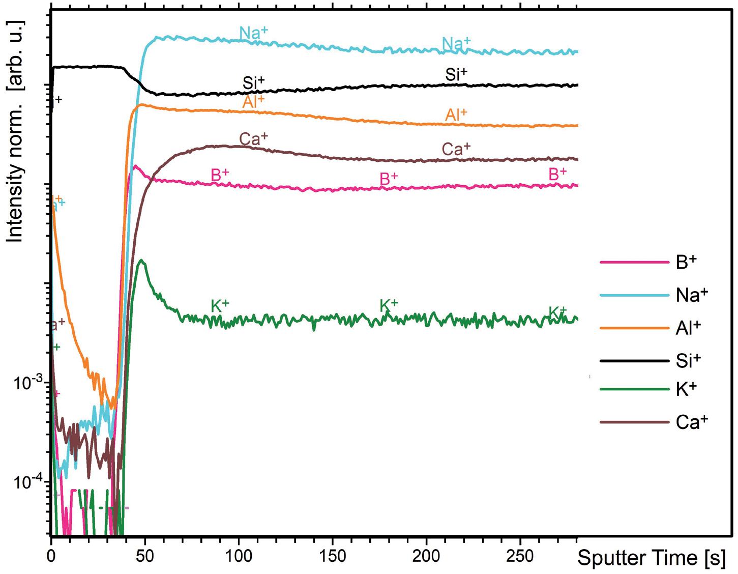
the washing process prior to the container being filled with drug solution, as well as further alteration of the interior glass surface during storage with the drug solution.
Elastomeric components are the second part of the primary packaging system that have contact with the drug product. These are predominantly vial stoppers (serum and lyo), syringe and cartridge plungers, syringe tip caps and cartridge seals. The base material chemical families of the majority of closures used in the pharmaceutical industry are halobutyl-based rubbers, specifically bromo- and chloro-butyls. Other closure system base materials in use are nitrile, butyl, thermoplastic elastomers, styrene-butadiene and polysiloxane. Barrier films and laminates made of ethylene tetrafluorotheylene (ETFE) and polytetrafluoroethylene (PTFE) are often applied to reduce leachables and particulate shedding. Silicone oil or crosslinked silicone coatings are used to improve machineability during assembly.
Due to the large range of compositions, laminates and coatings used for elastomeric closures, identity testing and verification is beyond the scope of USP <381> and Ph Eur 3.2.9. Nevertheless, identity testing is still required, as the corresponding guidance chapter, USP <1381>, states
that it is the responsibility of the drug product manufacturer and the component supplier to verify composition and confirm the identity of materials, while Ph Eur 3.2.9. demands that the drug manufacturer requests evidence from the supplier that the composition does not vary and is identical to that used during compatibility testing.
The USP and Eur Ph recommend several possible identification testing methods, such as ash content determination, sulfur determination, specific gravity, chromatography of component extract, attenuated total reflectance Fourier transform infrared spectroscopy (ATRFTIR), ultraviolet absorption of component extract and FTIR of component extract pyrolysate. The most informative for the purpose of elastomeric component material identification is chromatography of component extract to determine the elastomer’s chemical family and ATR-FTIR to determine the presence or absence of coatings and lubricants, as well as to further confirm the elastomer’s chemical family. Both methods are used for so-called “fingerprint identification”. For ATR-FTIR analysis, stopper samples are prepared to analyse:
• the drug product contact surface
• the non-drug product contact surface
• the bulk interior surface (i.e. crosssection).
A systematic inspection of the visual appearance and geometry is a useful first step in narrowing down and eliminating various stoppers (Figure 3). Determination of the chemical family of the base elastomer
is performed by gas chromatographymass spectrometry (GC-MS) analysis of a stopper extract and an ATR-FTIR assessment of the bulk stopper material. The GC-MS analysis of an unknown
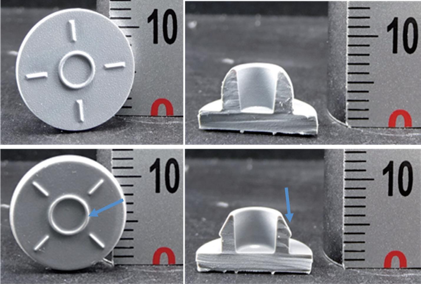
serum stopper sample extract is shown in Figure 4 as a mirror plot, showing good accordance with the corresponding analysis of an extract of a reference bromobutyl rubber stopper from manufacturer “A” conducted under the same conditions.
An ATR-FTIR analysis of the bulk spectrum of the unknown sample confirms a best-fit match to the same bromobutyl rubber reference stopper cross-section spectrum (Figure 5).
The next step is to determine the presence or absence of a barrier coating or film on the elastomer’s face that will be in contact with any drug product and the presence or absence of a siliconising agent.
An ATR-FTIR analysis of the unknown stopper sample’s drug product contact surface spectrum versus its bulk spectrum (Figure 6) confirms that a deliberately applied barrier coating or film was not present on the stopper. An ATR-FTIR analysis of the non-drug product contact surface of the unknown sample versus the bulk spectrum (Figure 7) confirms that a deliberately applied siliconising agent was present on the non-drug contact surface, as shown by the presence of an Si-CH3 band at 1260 cm-1
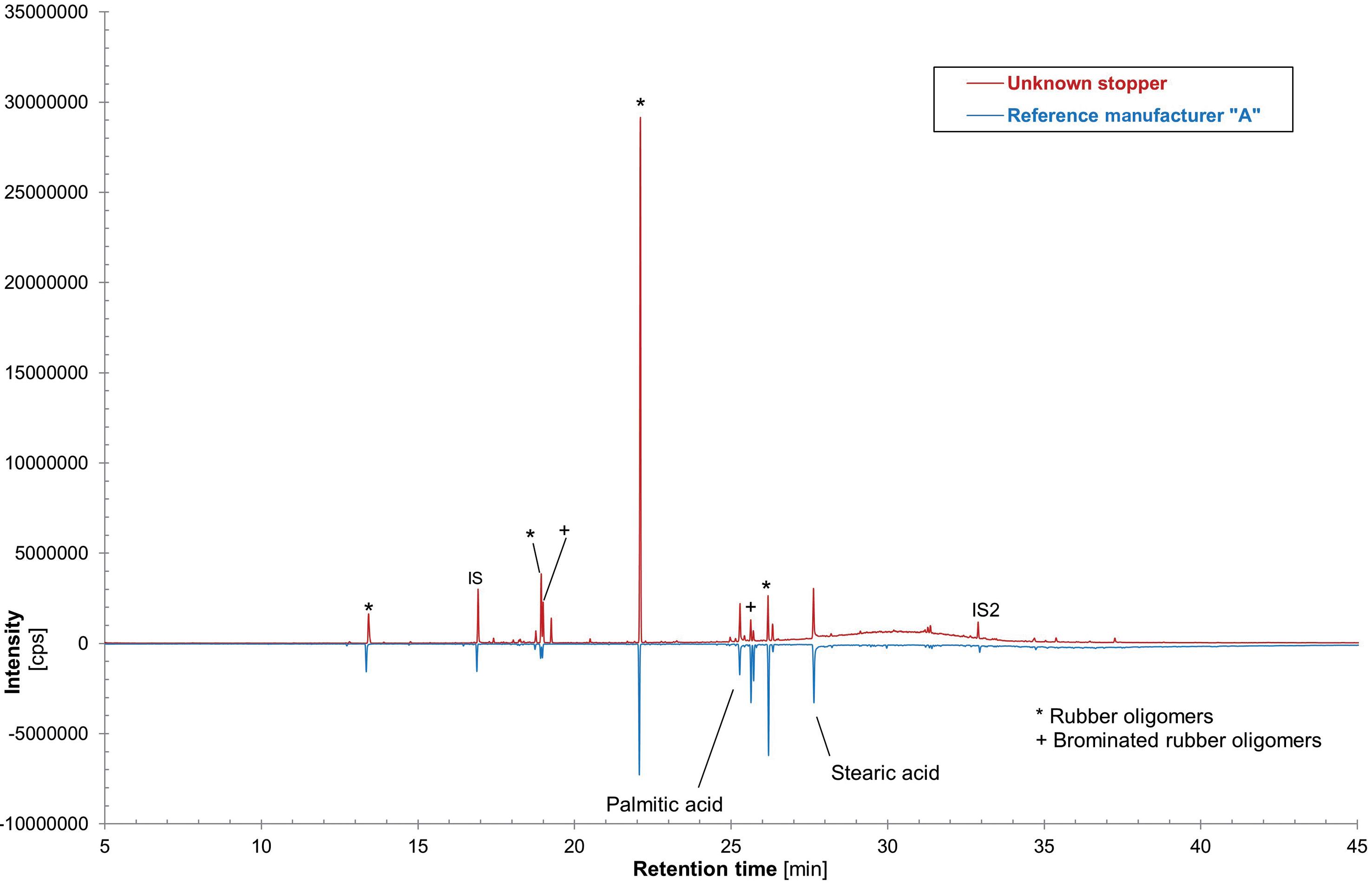
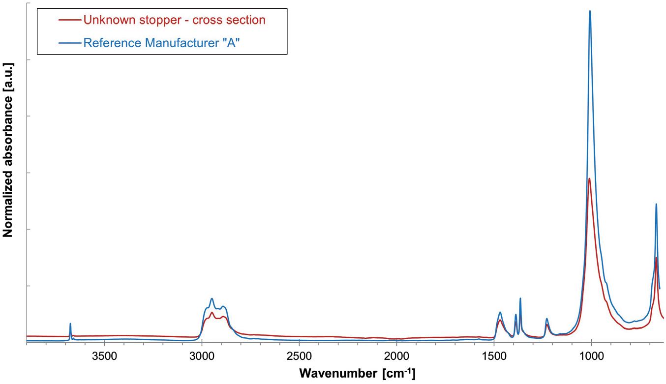
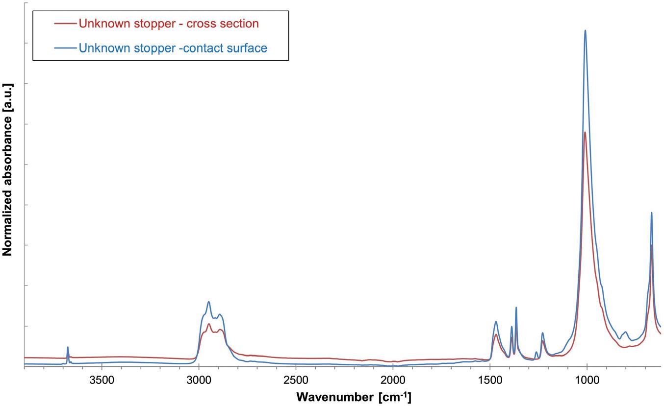
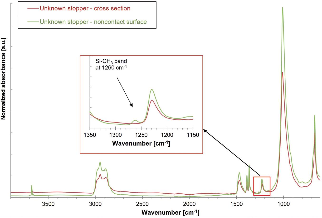
“To
achieve
the
successful identification and verification of primary packaging components requires a well-equipped laboratory, capable of conducting a variety of validated wet chemical, chromatographic, spectroscopic and physical measurement methods.”
For polymer components, the same methods can be applied for characterisation and identification as for rubber components. As an example, for polymer syringes, the polymer type can be identified by a combination of ATR-FTIR and GC-MS, while the silicone and lubrication can be identified by the methods described in Table 2.
The composition and manufacturer of a given glass container or elastomer closure component can be readily identified and verified using as-received samples or marketed packaging systems by combining various component attributes, such as appearance, colour and dimensions, with the chemical identity of the base material and coating composition, along with any lubrication or surface treatment. To achieve the successful identification and verification of primary packaging components requires a well-equipped laboratory, capable of conducting a variety of validated wet chemical, chromatographic, spectroscopic and physical measurement methods.
A comprehensive allocation of the analytical methods and tools, as well as the properties of packaging material that can be characterised by them, are shown in Table 2. Along with the necessary hardware, experienced staff, including inorganic and organic materials scientists and analytical chemists and physicists, with broad knowledge of primary packaging raw materials, manufacturing and processing methods, as well as a keen understanding of the various regulatory requirements, is essential.
Coating
Table 2: Comprehensive summary of the analytical methods that can be used to characterise the different properties of packaging material components.
SCHOTT Pharma designs solutions grounded in science to ensure that medications are safe and easy to use for people around the world – because human health matters. The company’s portfolio comprises drug containment and delivery solutions for injectable drugs ranging from prefillable glass and polymer syringes to cartridges, vials and ampoules.
SCHOTT Pharma employs a team of around 4,700 people from over 65 nations to contribute to global healthcare. The company is represented in all main pharmaceutical hubs, with 16 manufacturing sites across Europe, Asia and North and South America. With over 1,000 patents and technologies developed in-house, a state-of-the-art R&D centre in Switzerland and around 130 employees in R&D, the company is focused on developing innovations for the future.
SCHOTT Pharma, headquartered in Mainz
(Germany), is part of SCHOTT AG and owned by the Carl Zeiss Foundation, and so is committed to sustainable development for society and the environment and has the strategic goal of becoming climate neutral by 2030.
1. “ASTM E438-92(2018) Standard Specification for Glasses in Laboratory Apparatus”. ASTM, Jan 2018.
2. “Interim Revision Announcements (IRAs)”. Web Page, USP-NF, accessed Apr 2024.
3. “USP is announcing a proposal to modify the glass classifications in General Chapter <660> and to create additional flexibility for packaging and storage requirements in specified monographs”. USP-NF, Jan 2023.
4. “FIOLAX® clear”. Data Sheet, SCHOTT, accessed Apr 2024.
5. “Pharmaceutical Glass Tubing”. Product Brochure, Corning, 2022.
6. “BORO-8330™”. Data Sheet, SCHOTT, accessed Apr 2024.
7. “FIOLAX® amber”. Data Sheet, SCHOTT, accessed Apr 2024.
8. “ISO 8362-1:2018 Injection containers and accessories –Part 1: Injection vials made of glass tubing”. International Standards Organization, Aug 2018.
9. Boltres B, “When Glass meets Pharma: Insights about glass as primary packaging material”. Editio Cantor, Jun 2015.
10. Pillai SA et al, “Pharmaceutical Glass Interactions: A Review of Possibilities”. J Pharm Sci & Res, 2016, Vol 8(2), pp 103–111.
11. Ogawa T et al, “Comparisons of Aluminum and Silica Elution from Various Glass Vials”. Chem Pharm Bull (Tokyo), 2016, Vol 64(2), pp 150–160.
12. Rothhaar U, Haines D, Scheumann V, “Silicone Oil Induced Effects in Pharmaceutical Glass Vials Testing Methods for Visualisation, Identification and Quantification”. Pharm Ind, 2022, Vol 84(1), pp 120–127.
13. Crawford A, Zuccato D, Hladik B, “Effective Alternatives for Ammonium Sulfate Treated Pharmaceutical Glass Vials”. Pharm Ind, 2021, Vol 83(1), pp 139–147.
14. Bronnbauer C, “Glass Breakage in Pharmaceutical Packaging “. PDA Letter, Nov 2018.
15. Roehl H et al, “Risk Mitigation of Drug Shortages-A New Concept for Vials Designed to Improve Fill and Finish Performance”. PDA J Pharm Sci Technol, 2021, Vol 75(2), pp 141–156.


Uwe Rothhaar, PhD, is Director at SCHOTT Pharma Services. He earned his PhD in Physics in the field of surface and thin film characterisation and has remained connected to analytics in various positions he has held during his career.
Daniel Haines, PhD, is Head of Pharma Services North America at SCHOTT Pharma Services, with responisbility for laboratory activities and customer relations in North America. He holds a PhD in Inorganic Chemistry and has over 20 years’ experience in the field of drug/container interactions.


Matthias Bicker, PhD, is a Scientific Advisor at SCHOTT Pharma Services and is an expert in customised test designs, including alignment with the most recent regulatory guideline recommendations. Dr Bicker holds a PhD in Physics in the field of nanostructures in thin film coatings.
Thomas Schmidt, as Study Director at SCHOTT Pharma Services, is responsible for the planning and assessment of studies concerning the qualification and quantification of extractables and leachables across diverse materials. Mr Schmidt holds a master’s degree in Chemistry with a focus on pharmaceutical analysis, and possesses extensive experience in organic analysis, specialising in GC-MS, HS/GC-MS, HPLC-UV/VIS and HPLC-qTOF.
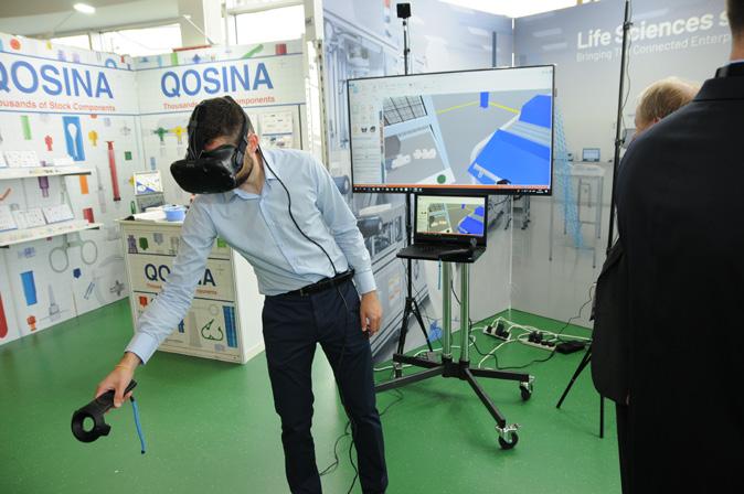


Rely on SCHOTT Pharma’s independent and accredited laboratory for precise packaging component characterization, providing reliable data for your packaging requirements. Count on our expertise in analyzing elastomeric, polymeric and glass compositions to ensure the safety of drug storage.


SCHOTT Pharma AG & Co. KGaA
www.schott-pharma.com/packaging-component


Vetter Pharma is a leading global contract development and manufacturing organisation (CDMO) for the aseptic production of injectables (Figure 1). Since its founding in 1950 in Ravensburg (Germany) as a family-owned pharmacy,
Vetter has grown to over 6,300 skilled employees worldwide. The company operates commercial production sites in Ravensburg and Langenargen (Germany) and clinical production facilities in Rankweil (Austria) and Chicago (IL, US) to
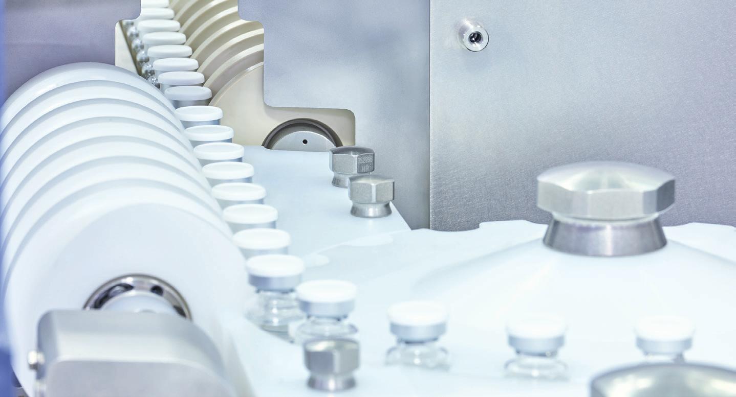

supply patients worldwide with potentially life-saving drugs, as well as branch offices for Asia Pacific in Singapore, Japan, South Korea and China.
The company has international expertise working with regulatory authorities including the US FDA, EMA, PMDA (Japan) and RP (Germany). Vetter offers services for pharma and biotech firms of all sizes and locations and holds numerous patents, including technologies for protection against tampering and counterfeiting. Vetter’s expertise ranges from lyophilisation (freeze-drying) to siliconisation and more.
Vetter’s mission is to produce drugs that enhance patient safety, comfort and compliance by providing tailored solutions to meet their partners’ specific market needs. The company has been carbon neutral at all its corporate sites since 2021.
As a globally operating CDMO partner, Vetter produces aseptically prefilled syringes, cartridges, vials and dual-chamber systems (Figure 2). It is an independent company rooted in over 70 years of history.
“Vetter offers services for pharma and biotech firms of all sizes and locations and holds numerous patents, including technologies for protection against tampering and counterfeiting.”

“Vetter supports its customers from the initial phases of clinical drug product development and filling through to commercial manufacturing, device assembly, packaging and lifecycle management.”
Vetter does not manufacture its own drugs, instead focusing on providing highly skilled support and state-of-theart manufacturing resources to pharma partners. Vetter supports its customers from the initial phases of clinical drug product development and filling through to commercial manufacturing, device assembly, packaging and lifecycle
management (Figure 3). More than 80% of the company’s active projects are biologics.
Vetter’s portfolio of services includes dedicated resources for clinical development; commercial manufacturing, assembly and
packaging; and more. Vetter offers the following services:
• Drug Product Development: Support in navigating key decisions early in a product’s evolution with scalability, quality and efficiency in mind.
• Aseptic Filling and Visual Inspection: Comprehensive expertise in manufacturing injectable drug products and related visual inspection systems.
• Device Assembly and Packaging: Strategic, technical and packaging support for patient-friendly combination products.
• Analytical Services: Robust, customisable testing methods for drug products, including evaluation and quality verification.
• Regulatory Support : Support in achieving milestones related to regulatory compliance during clinical development, market authorisation and beyond.
• Logistic Services: Cutting-edge solutions that maximise efficiency, transparency and precision of vital supply chains.
Vetter Pharma International GmbH Schützenstraße 87 88212 Ravensburg Germany
T: +49 75 137 000 E: info@vetter-pharma.com (EU/APAC) infous@vetter-pharma.com (US)
www.vetter-pharma.com

* using Forest Stewardship Council® certified recycled paper, vegetablebased inks, biodegradable laminates and carbon balanced materials offset via the World Land Trust™ following ISO140001 processes.
** by DHL using GoGreen Plus carbon insetting of at least 30% through the use of Sustainable Aviation Fuel (SAF), a biofuel substitute for traditional jet fuel, produced from renewable sources. Mailed to individual readers outside the UK by DHL using GoGreen, which offsets 100% of CO2 emissions.


have relied on Vetter to put their parenteral medications on a path to success. We’re proud to help advance your innovative therapy with flexible, robust, scalable processes and services that set our partnership apart:
• Specialized support for your unique clinical development program
• High-quality aseptic filling at both clinical and global commercial scale
• Strategic packaging and device assembly solutions that span your product’s life cycle
• Comprehensive technical, analytical, and regulatory expertise at every step