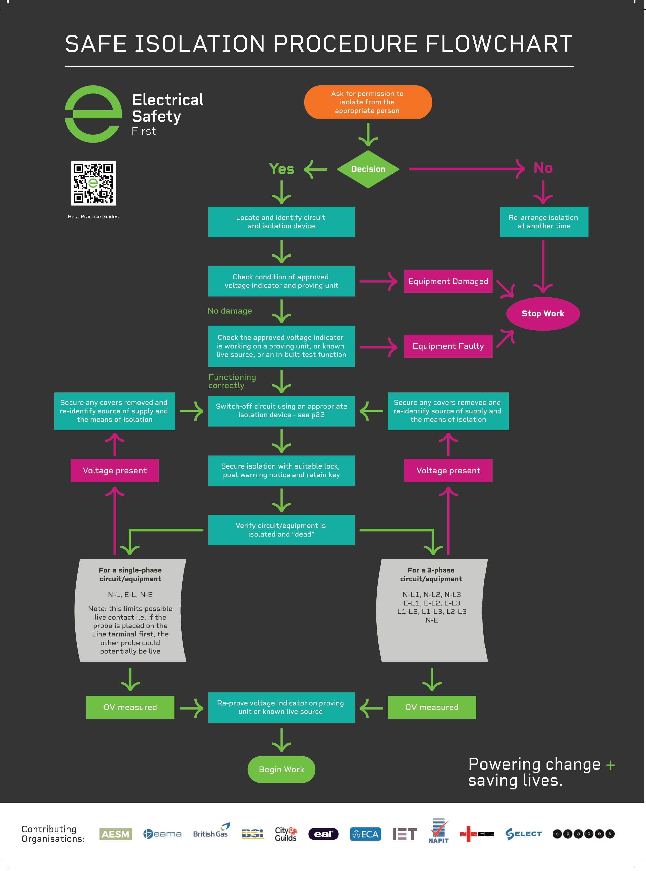
7 The key steps to correctly achieving safe isolation
8 The team at NAPIT ‘codebreak’ more of the latest reader submissions
11 Guidance on suitable measures to prevent and mitigate the risk of spread of fire and smoke when installing wiring systems
14 What’s the value in designing an electrical system?
16 How to choose and use the right socket tester
18 Unravelling the mysteries of fault detection
20 What is corona discharge and what causes it?
22 Considering some types of RCBOs and their applications, along with the relevant requirements of BS 7671
43 Looking into suitable means of support for wiring systems
44 How to best avoid a clash with your emergency signs
46 The team at NAPIT ‘codebreak’ more of the latest reader submissions
48 What has changed with the energy ratings displayed on light bulbs?
50 Changes to the requirements for insulation resistance testing and the key considerations for those carrying out such procedures
52 Why does pink sleeving need to be used for functional earths?
49 Exploring fire performance cables in more detail
25 Looking into the practicalities and requirements of BS 7671:2018+A2:2022 with respect to isolation and switching for mechanical maintenance
28 Dr Zzeus, Tom Brookes, answers another fire-related question
30 Understanding concealed cabling and how to deal with new and existing cabling
33 What fuse do you need for a Type 1 SPD?
35 An introduction to overload current and how the requirements for this in BS 7671 are to be applied
38 The team at NAPIT ‘codebreak’ more of the latest reader submissions
40 How are networks configured and how do they operate?
58 Understanding electrical installations in medical locations
60 Dr Zzeus, Tom Brookes, answers another fire-related reader question
62 The team at NAPIT ‘codebreak’ more of the latest reader submissions
64 RCD Types and applications for EV charging installations
66 An introduction to emergency lighting
69 The importance of understanding and applying electrical formula
72 The dangers of working with asbestos and the solutions that are available to stop fire alarm installers coming into direct contact with it
74 The problems associated with inferior quality connector products
76 Bonding issues and extraneous-conductive-parts in electrical installations
78 How to verify the quality of the emergency lighting products you’re fitting
80 A look at the practice of unfused spurs off a ring final circuit
82 The team at NAPIT ‘codebreak’ more of the latest reader submissions
84 How earth electrode resistance can be improved as part of a planned approach to installation


continuing professional development (CPD) can be broadly defined as any type of learning you undertake which increases your knowledge, understanding and experiences of a subject area or role.
To help professionals to better document and prove this process, the CPD Book contains content and articles that have been checked, verified and accredited by a third-party specialist organisation.
Collectively, the content within this specially designed publication has been deemed worthy of 5 CPD credits, or 5 hours’ worth of CPD, with each individual section providing 1 credit, or 1 hours’ worth of CPD.
Once this content has been consumed, readers will have the

opportunity to scan a QR code which will provide a bespoke, downloadable certificate that can be used as part of a professional’s ongoing CPD record.
DO NOT SCAN THE QR CODE UNLESS YOU HAVE READ ALL OF THE CONTENT WITHIN EACHSECTION!
A large element of CPD involves self-certification and relies on professionals being honest about what they have actually read, consumed and digested. A QR code has been placed with the final article in each of the five learning sections within this publication and ONLY once you have read ALL of the articles within each section, should you then scan the code to receive your bespoke certificate.
By skipping any of these steps, you’re not just cheating the system, but yourself and your fellow professionals at the same time!
NEW USERS –ACCESS YOUR BESPOKE CPD CERTIFICATE IN FIVE STEPS
1. Read ALL of the content and articles included within the five sections.
2. Find the QR code with the last article in each section and scan.
3. Enter your email address.
4. Fill out your details on the contact form.
5. Download your certificate for use as part of your annual CPD record.
PREVIOUS USERS –ACCESS YOUR CPD CERTIFICATE IN FOUR STEPS
1. Read ALL of the content and articles included within the five sections.
2. Find the QR code with the last article in each section and scan.
3. Enter your name and email address.
4. Download your certificate for use as part of your annual CPD record.
All certificates are valid for one year from the issue date. If you’re having any issues with downloading your certificate or using the system, please email us at: pe@hamerville.co.uk

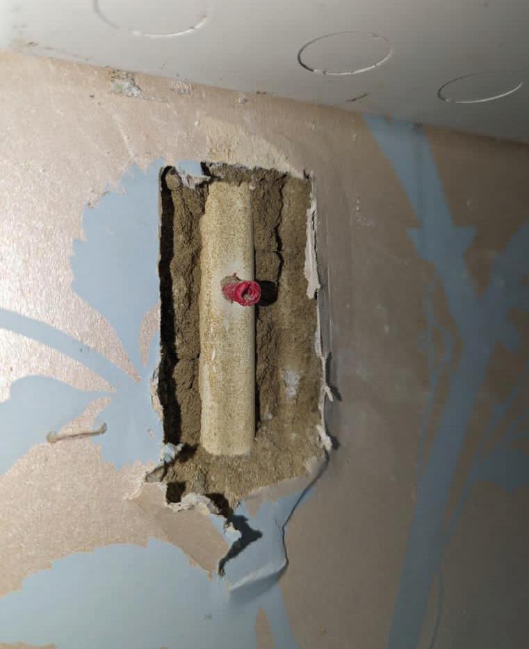
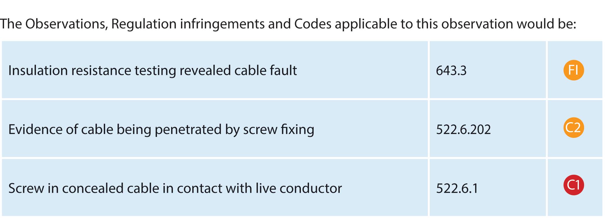
The positioning of concealed cables is covered within BS 7671, although this is one of the best kept secrets that consumers are not aware of.


As the cable is well within 50 mm from the surface, the prescribed zones allow for cables to be installed horizontally or vertically to an electrical point, accessory or switchgear. Because the cable is directly below the consumer unit it would meet the requirements of BS 7671 and in particular Regulation 522.6.202.
It looks like there was plaster removed to find the damage to the cable and I would assume that there was also a fault on the cable. Although the wall plug is plastic, I doubt if it would act as an insulator with the screw in place.
Hopefully, there was an RCD installed to provide additional protection for the circuit. If not, the installation may have been designed to an earlier edition of BS 7671 which did not require such protection.
The first classification code would be a Further Investigation (FI) to determine if this was the only area where a screw had penetrated this cable and to widen the inspection and testing to find any other cables with similar damage.


Updated for BS 7671:2018+A2:2022, NAPIT’s EICR Codebreakers publication is purpose-written to aid contractors, inspectors and clients, and now includes updates to align with Amendment 2 of the IET 18th Edition Wiring Regulations. The book is the perfect technical aid for electrical professionals and their customers.


Need help with cracking those all-important EICR codes? Every month the technical team at NAPIT will be studying your latest ‘Caught on Camera’ photos and offering advice on the next steps, should you find a similar installation. If you want the team at NAPIT to help crack your codes then send your pictures through to us at: pe@hamerville.co.uk


JOHN COOMBS: I BET THIS IS THE FIRST TIME YOU’VE SEEN THE SEALING CAP USED FOR AN OUTSIDE SOCKET? UNSURPRISINGLY, IT WAS CARRIED OUT BY A BODGING
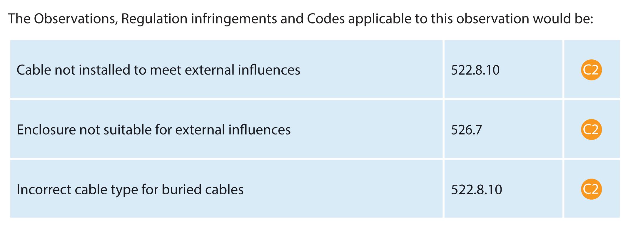
Where cables are buried in the ground they have to be protected against mechanical damage with the best method of using a Steel Wire Armoured cable installed at an appropriate depth with a cable duct or some other means of protection, including a marker tile or tape, indicating the presence of a buried cable in line with Regulation 522.8.10.
In this case there does not seem to be any precautions for any of the above for this cable installation. A joint has been made for an ‘additional socket’ and the proprietary cable jointing kit has been used for a purpose that it was not intended for.
The additional socket has a cable connected via the compound filling hole which is not suitable for the termination of any cables. The cable type for the additional socket appears to be twin and earth covered in insulation tape to protect it from the external influences and fails to meet the requirements for buried cables with an earthed armour or metal sheath or both.
By using incorrect termination methods this joint could be liable to ingress of moisture and lead to the failure of a connection.
As the jointing kit has been used outside of the manufacturer’s requirements, including the product standards, the installation would have to be considered as a departure from BS 7671. This would not be
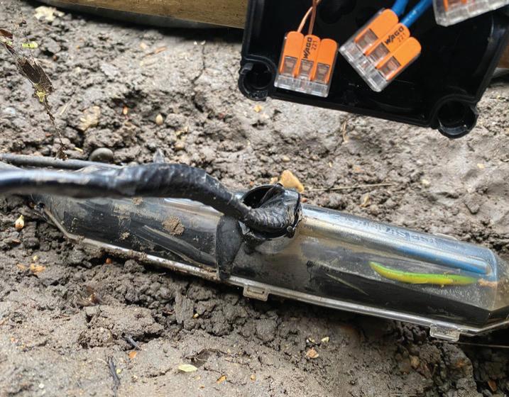
accepted as this method of installation could not be considered no less safe than if it had complied with the requirements. Therefore, the classification code would be a potentially dangerous C2 for incorrect termination, location of buried cables and cable type.


The A2:2022 18th Edition Codebreakers publication is priced at £22.00 (members) and £24.00 (non-members). It is available in both hard copy and digital versions * Price is VAT exempt and excludes postage and packaging.


The aim of this article from the experts at NICEIC is to provide guidance on suitable measures to prevent and mitigate the risk of spread of fire and smoke when installing wiring systems that penetrate the building fabric.
This article considers the methods for fire sealing where wiring systems and openings are made within the building fabric during electrical installation work.
One of the most commonly recurring non-compliances seen during an annual assessment is the absence, or inadequate sealing, of cable penetrations passing through the fabric of a building.
A fire can spread rapidly through a building where permanent openings are present and especially where flammable materials are often used for construction. The need to provide fire sealing is a fundamental requirement of the Building Regulations in England, Wales, Scotland and Northern Ireland and is recognised in Regulation Group 527.2 and Appendix 13 of BS 7671
It is important to remember that the integrity of the fire resisting linings must be maintained throughout the building’s construction.
Fire sealing
The risk of spread of fire, and of the products of combustion such as smoke,
fumes and flammable gasses should be minimised by the selection of appropriate materials and sound installation work practices (527.1.1). The installation of a wiring system shall not detrimentally affect either the structural integrity or fire safety of a building (527.1.2).
The requirements of Regulation Group 527.2 and the relevant building regulations are intended to preserve the:
● fire separation between areas of the building; and
● structural stability of the premises in the event of a fire.
It is recognised that, in most domestic type premises, it is the loadbearing capacity of floors that is threatened by early failure of the ceiling linings due to fire.
The requirements to seal openings apply wherever a wiring system passes through an element of building fabric having specific fire-resistant properties. The ability of the element to resist the spread of fire once breached is
likely to have been compromised. Regulation Group 527.2 highlights the need for sealing such elements especially where wiring or cable management systems have penetrated the fabric of a building’s construction, including floors, walls, ceilings and the like.
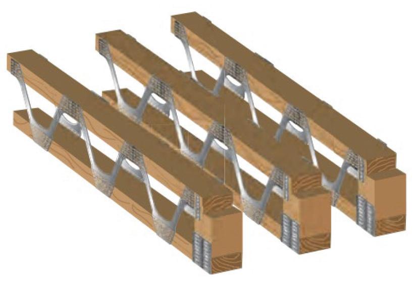
Many modern forms of engineering construction use Structural Insulated Panels (SIPs) and include other elements such as timber and plywood ‘I’ beams (see Fig 1), metal webbed beams (see Fig 2) and the like which inherently have reduced levels of fire resistance in comparison to more traditional solid timber joists.
Consequently, they are more heavily

plasterboard and similar linings as a means to provide the required level of fire separation needed to protect the structural elements.
Sealing requirements
Where it is necessary to make openings for cables and cable containment systems and the like, within an element that has specific fire-resistant properties, these should be kept to a minimum and should be as small as practicable.
Regulation Group 527.2 requires both:
● external sealing around the wiring system; and
● internal sealing.
Where a wiring system classified by a relevant product standard as non-flame propagating has an internal cross-sectional area not exceeding 710 mm2 (approximately 32 mm diameter) it need not be internally sealed (527.2.3).
Note: A non-flame propagating wiring system is one that is liable to catch fire when exposed to a flame, but the flame will fail to spread along the wiring system and will extinguish itself within a limited time. Such wiring systems must be in accordance with the relevant British Standards.
The fire resistance of the element of the building construction shall be restored to the original level of fire-resistance (if any) present prior to penetration by the wiring system (527.2.1).
Regulation 527.2.4 requires the sealing arrangements to resist external influences to the same degree as the wiring systems
with which they are used and to meet all of the following conditions:
● Be resistant to the products of combustion to the same extent as the element of the building’s construction which has been penetrated.
● Provide the same degree of protection from water penetration as required for the element of the building’s construction in which it is to be installed.
● Be compatible with the material of the wiring system with which it is in contact.
● Allow thermal movement of the wiring system without reduction of sealing protection.
● Have adequate mechanical stability to withstand any stresses that may arise through damage to the support of the wiring system due to fire.
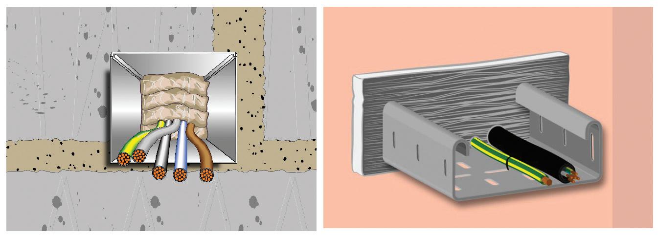
Various types of fire-stopping products can be used for internal and/or external sealing of penetrations, including intumescent mastics/gaskets, pillows, compounds, and metal sleeves. The term ‘intumescent’ is used when referring to materials which expand to provide a seal when exposed to a source of heat.
Depending on the type of product used, a typical seal may be suitable for single or multiple penetrations and have the ability to withstand direct heat from a fire for a prolonged period of time; hours in some cases.
Guidance on the use of suitable
products for a particular application should be obtained from a competent person/authority at the design stage of the installation. In addition, manufacturers’ data should always be taken into consideration.
It’s worth noting that Clause 24.4.2 of BS 9991: 2015, Fire safety in the design, management and use of residential buildings – Code of practice, considers materials such as cement mortar, gypsum-based plaster and vermiculite (cement or gypsum-based) as being suitable for fire-stopping in residential premises and the sealing of gaps not exceeding 25 mm where expected movement is limited.
During the erection of a wiring system temporary sealing arrangements shall be put in place (527.2.1.1). This normally involves the use of removable fire-stopping products such as intumescent pillows, or sleeves, as shown in Fig 3. This method of fire-stopping is often used in trunking or between dividing walls where cables and the like pass through one area and into another on a cable tray.
Where it has been necessary to disturb a sealing arrangement or fire/smoke barrier during alteration work, these prevention methods shall be reinstated as soon as practicable (527.2.1.2). The applied reinstatement should be of the same type of materials/components as were originally used.
The mixing and matching of systems and components is not supported by manufacturer’s fire test data and so may compromise the fire integrity of the installation. Where it is not possible to
ascertain the components used for the original seal, the whole seal/prevention method should be replaced.
Many buildings incorporate cavity walls having a stud and plasterboard construction. Such types of structure provide a natural route for the spread of fire and smoke, which in most cases would spread unseen.
Where the wall provides fire separation, and where the lining is relied on to resist collapse, appropriate measures shall be taken to maintain the fire integrity of any walls when incorporating installed equipment and/or accessories such as a consumer unit, cavity boxes and the like.
Cable entries made in accessories and equipment must be provided with suitable sealing arrangements including intumescent gaskets, grommets and/or fire sealants to maintain the degree of
fire integrity (if any) provided by the equipment.
However, it must be recognised that not all fire-rated products qualify as a suitable fire-stopping product. For example, some expanding polyurethane (PU) foams which are suitable and tested for sealing linear gaps are not tested or suitable for cable or pipe penetrations likely to be exposed to thermal expansion or movement. In all cases manufacturers’ product data must be considered.
This article has highlighted the importance of maintaining the fire integrity of an element within a building’s construction to preserve structural stability after penetrations have been made for the passage of wiring systems. Where it is necessary to breach a fire barrier, any openings or gaps made should be kept to a minimum and be as small as practicable.
The need to apply appropriate fire sealing products and installation methods must be considered where such building elements have been compromised.
Any sealing arrangements which have been removed or compromised during construction must be reinstated as soon as is practicable and during the installation of a wiring system.
Temporary sealing arrangements should be provided where appropriate.
Guidance on the necessary sealing arrangements and use of suitable products for a particular application should be obtained from a competent person/authority at the design stage of the installation. In all cases manufacturers’ product information and instructions for general use should be considered.


Raphael Magnus, Managing Director at Safe-Electric, looks at the legal and ethical reasons that dictate the value of a properly designed electrical system.
In my experience, too many electricians don’t bother designing, preferring instead to use the old 'guestimate’ method while completely ignoring that statutory document that so few take any notice of –HSR-25 –otherwise known as the Electricity at Work Regulations 1989.
As an electrical professional, the greatest defence that can protect you is proof of design, yet this is often completely ignored because nobody
allows for the cost of doing it correctly, so why bother?
The answer to that question becomes very apparent when it goes wrong – wait and see how quickly designers are then asked to produce something to cover you because it got legal. Unfortunately, doing something after the fact won’t be enough to protect you; by that stage, it’s too late!
The BS 7671:2018 Amd 2 ‘Brown Book’ Regulation 132 design (page 24) makes it
very clear that electrical systems need to be designed before installation.
When I speak to electricians I’m often asked: “What has that got to do with us?” followed by the cry: “We only have to deal with BS 7671 and that isn’t law, it's just a BS code!
Well, let’s see how that stands up when you’re in a court of law waiting to find out if your life is about to be destroyed before your eyes.
In the opening statement of HSR-25, the very first paragraph says:
This new edition of HSR-25 will help duty holders meet the requirements of the Electricity at Work Regulations 1989. It will be of interest and practical help to all duty-holders, particularly engineers (including those involved in the design, construction, operation, or maintenance of electrical systems), technicians and their managers.
This means all of us!
Furthermore, it states under the SCOPE in HSR-25:
7 The Regulations apply to all electrical systems and equipment (as defined) whenever manufactured, purchased, installed, or taken into use, even if its manufacture or installation pre-dates the Regulations.
8 BS 7671 Requirements for electrical installations are also known as the IET Wiring Regulations. They are non-statutory regulations which ‘relate principally to the design, selection, erection, inspection and testing of electrical installations, whether permanent or temporary, in and about buildings generally and to agricultural and horticultural premises, construction sites and caravans and their sites’.
9 BS 7671 is a code of practice which is widely recognised and accepted in the UK and compliance with it is likely to achieve compliance with relevant aspects of the Electricity at Work Regulations 1989.
Looking through Guidance Section 11 in its entirety, I’ll draw your attention to Fault Level 174 and the following small extract: The design of the protective arrangement must also provide for sufficient current to be available to operate the protective devices correctly in respect of “all likely faults”
That is the key wording here.
Now bear in mind that without a proper upfront design and proof, you will not have a leg to stand on in a court of law, and forget rule 29 protecting you –it won't!

There are far too many installations where Guidance 14 - 205 is ignored, and not even considered in any design or operational conditions.
Extracts from HSR-25-2015
Ignoring the bits of BS 7671 just because you don’t like them is going to cost you extra money to do it correctly/safely, unless you can justify fully and prove categorically with design calculations that what you have done is correct/safe!
In bad circumstances, those who argue that you cannot be prosecuted under BS 7671 because it’s only a BS code need to think again!
You WILL be prosecuted under The Electricity at Work Act 1989 for non-compliance with BS 7671:2018 Amd 2-2022. Yet it’s something that many duty holders and the vast majority of electricians I speak to have no idea (or even care) about, in terms of how it affects what they do and their decisions.
You may also be interested to know that under the CDM-2015 regulations, all designersmust ensure the system is safe, and you must be able to prove this in a court of law.
Even, if all you’ve done is add a spur-off-the-ring circuit, can you prove with documented calculations and design
evidence that you’ve checked this is safe before installation?
There are numerous building acts that we have a legal responsibility to ensure we comply with, even if we don’t know about them. Yes, you heard that right, even if we don’t know about them
Under English law ‘ignorance of the law is no excuse’ so the use of statements like: “I did not know” or: “It was going to cost us too much, that’s why we did it that way” is not acceptable in your defence. This has been proven many times in our courts.
So often I hear: “But that’s what the client wanted!” It doesn’t matter – you’re the one who installed it, and you’ll be the one to take the legal responsibility at the end of the day.
My advice in that situation is to stand up and stop allowing clients to force you in a direction that you know is potentially unsafe, all because of cost. You must learn to say “NO”!
Many in our industry are trying hard to return to the basic principles of safety and high standards so that we can overcome the dangerous cowboy mindset that has crept in that cheaper and faster is better. It never is, and you’ll always end up paying twice the price just to put it right.
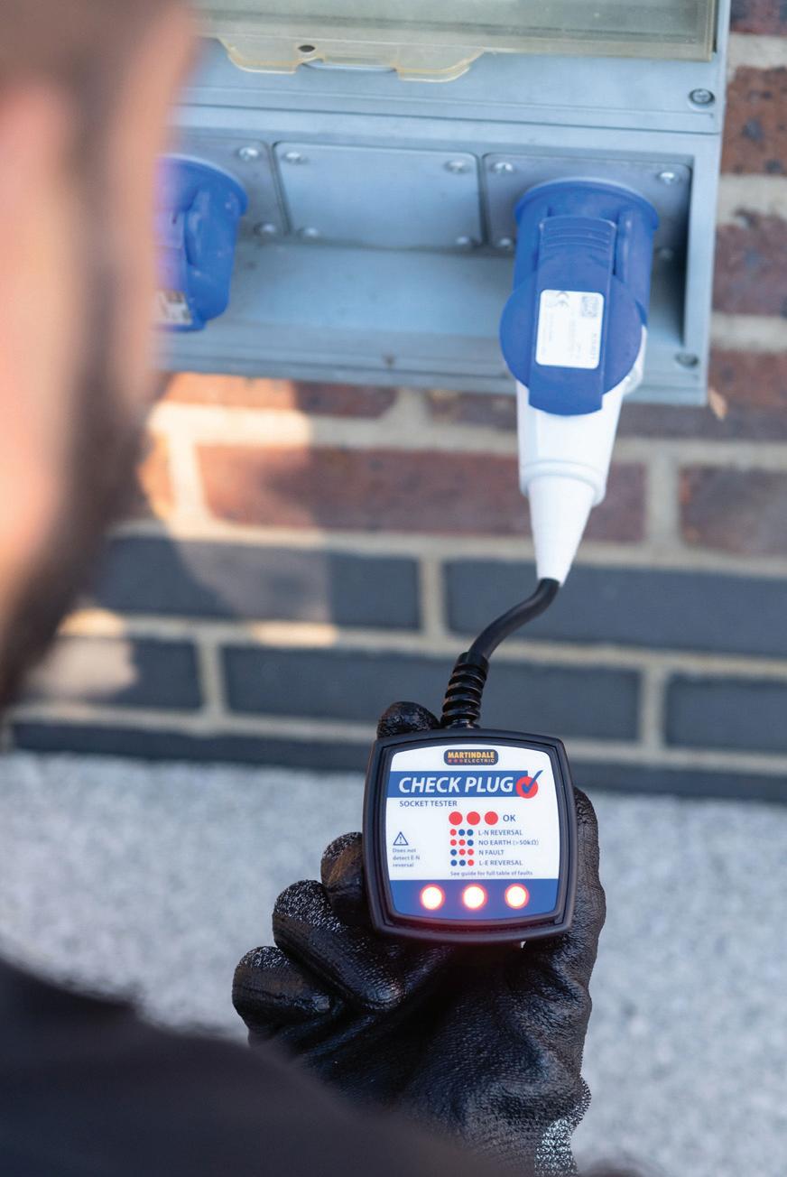
Steve Dunning, Managing Director of Martindale Electric, takes a closer look at how to choose and use the right socket tester.
Socket outlet testers (socket testers for short) have become very popular with electricians and contractors, but it’s extremely important to understand the limitations of this type of testing and the differences between the available types.
There are three main categories of socket tester: simple, advanced, and professional. All perform the basic tests to check that the earth, live and neutral, are correctly wired.
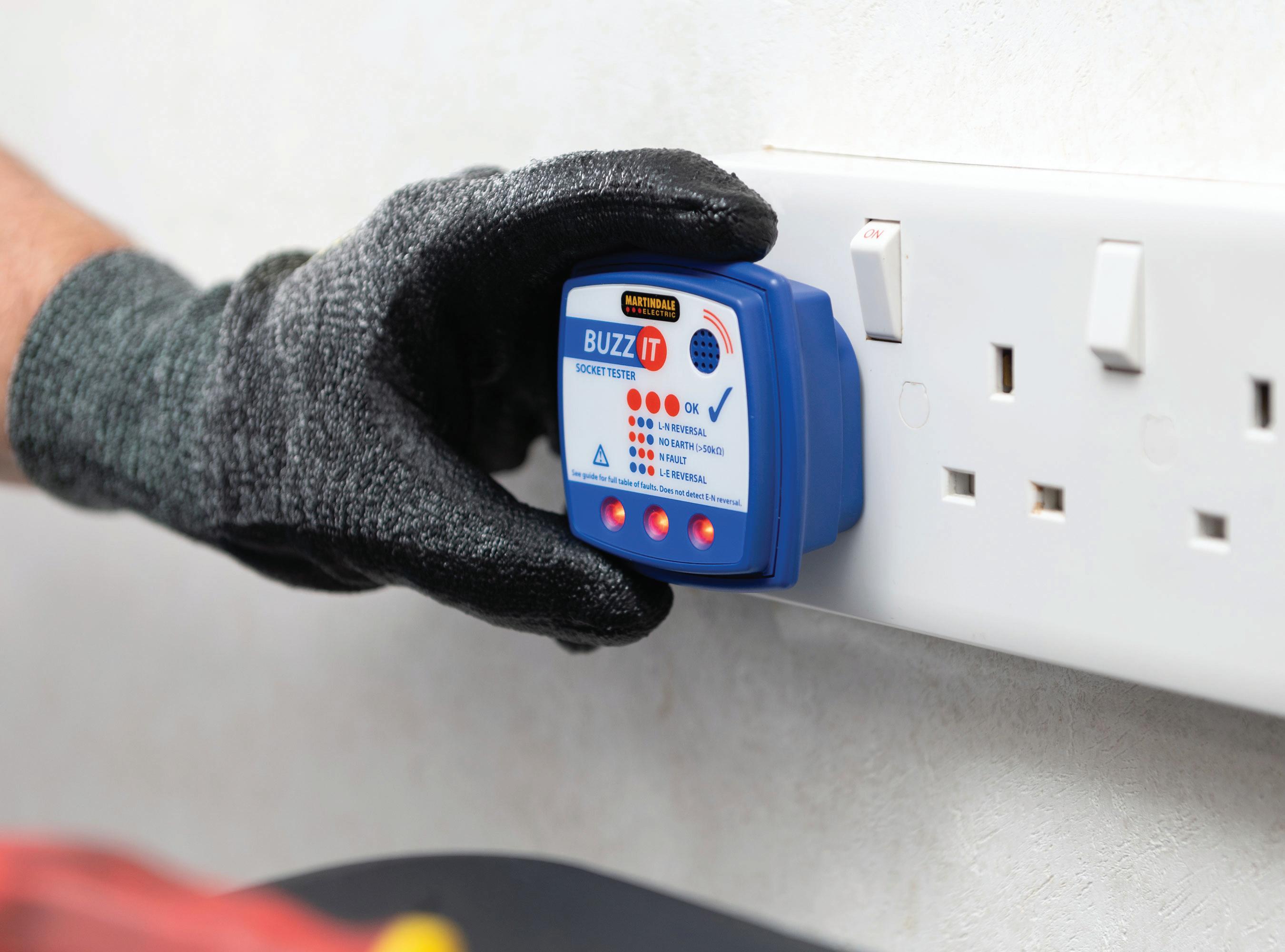
Test results are generally communicated to the user by LEDs and, in some units, by a buzzer. This not only indicates a ‘good’ or ‘faulty’ socket but should also use a combination of indicators to identify which fault type is present. All socket testers should show the absence of an earth connection;
however, advanced or professional classified testers will also help verify the quality of the earth.
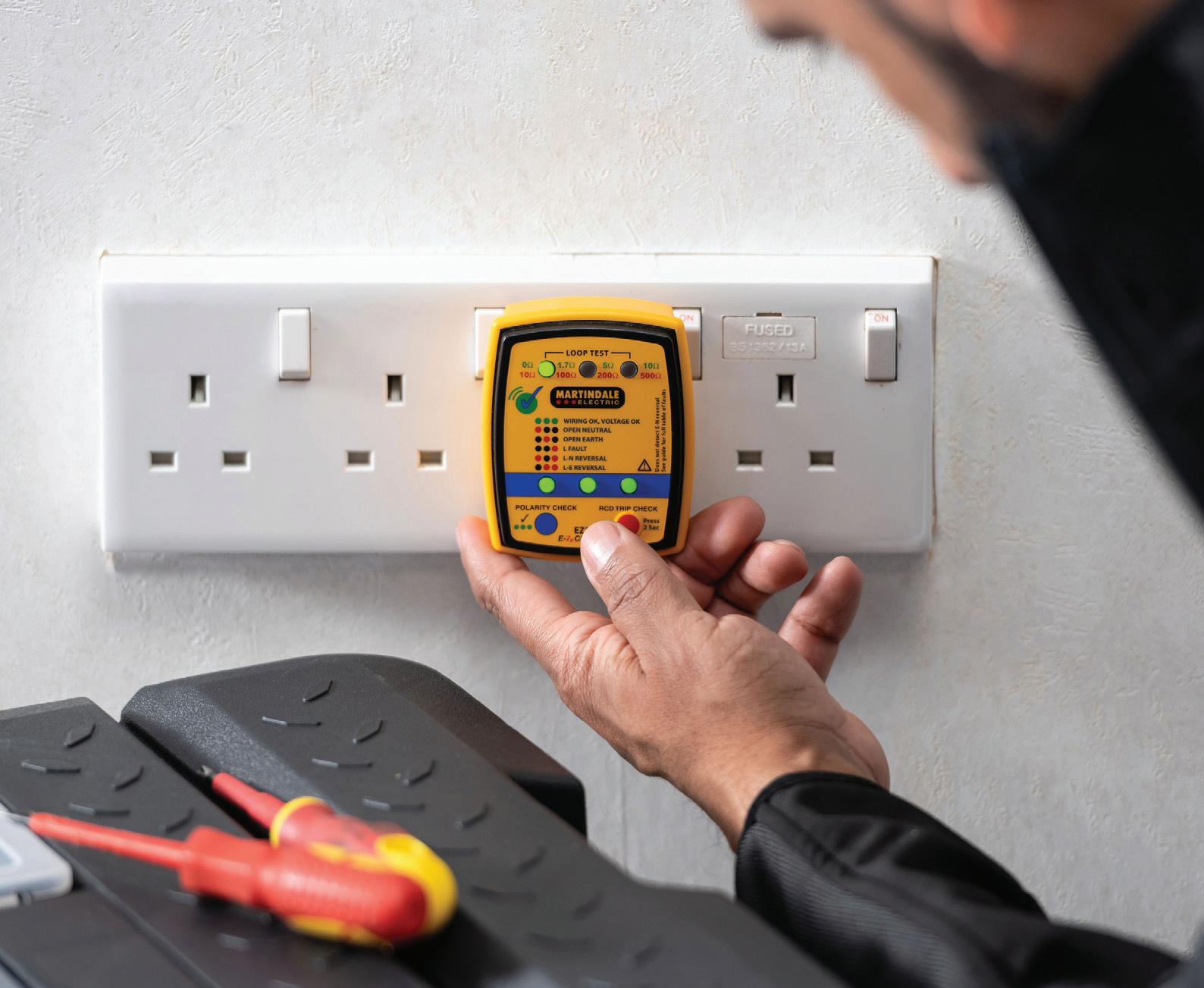
Advanced and professional categories measure and display ranges or numerical values for earth loop impedance, while the simple category will not show when earth fault loop impedances are excessive. For example, some recently introduced units will show you how good your earth is via resistance range indicators on the tester.
Understanding the differences in the categories is important; some basic socket testers have been seen to show an earth as ‘good’, even when the impedance is exceptionally high. Sometimes this is even at a level that is typically considered suitable for insulation; it’s clear that, in this case, the ‘protective’ earth will not protect.
Earth loop values higher than a few ohms can cause problems, for example, a reliable earth loop impedance indication is vital to ensure that some over-current protection devices react fast enough to avoid electrocution. Socket testers capable of indicating earth loop impedance reveal a lot more about the electrical safety of an installation than just a simple LED wiring fault indicator.
There is one fault that a socket tester and, indeed, no other piece of equipment can easily find: the swapping of the earth and neutral wires. This is due to the earth and neutral being common at the substation (if not closer), so electrically, they’re indistinguishable.
Although all socket testers can identify wiring faults at the socket, they will not detect when the incoming supply polarity has been reversed. This serious fault
condition requires an additional specific test to detect where L-NE connections have been reversed at the supply. This capability is included in some of the latest socket testers and is usually activated through a simple touchpad.
Other useful features available include an RCD test function to perform a basic trip test on a breaker associated with the socket under test. It should be remembered that this is a simple function test and doesn’t replace the RCD test as part of the 18th Edition regulations.
Many (even basic) socket testers include a buzzer to indicate the status of the socket. One advantage here is the tester can be used to help identify which socket is on which circuit, using the buzzer as an indicator while activating the circuit.
So far, we’ve looked at socket testers primarily for standard three-pin outlets, however, some manufacturers offer socket testers for the different types of sockets
used in commercial and industrial applications.
Industrial socket testers tend to perform some of the same basic tests as a standard 13 A device, but with the variety of different pin configurations including four and five pin three-phase type outlets, different potential voltage levels, it’s important to identify the exact requirements needed for the application and to check the manufacturer's specifications to identify which tests can be performed.
Always remember that BS 7671 requires new, repositioned, or repaired socket outlets not to be put into service until the necessary verification procedures have been completed.
These procedures include continuity testing of protective conductors and ring final circuit conductors, insulation resistance measurement, polarity
checking and earth fault loop impedance. A safe approach is to use the appropriate individual instruments or multifunction installation testers.
It’s important to appreciate that socket testers are not an alternative to the complete verification of wiring installations. However, they do offer a fast and effective solution to identify potentially unsafe installations and wiring faults when correctly specified as a first-line indicator.
They can also be helpful as a service tool in identifying potentially dangerous conditions before carrying out work on existing electrical systems and equipment, before installing new appliances or performing an initial check on sockets prior to full installation testing. GET MORE DETAILS ABOUT MARTINDALE’S RANGE OF SOCKET TESTERS AT:

An electrical fault isn’t a natural occurrence; rather, it is an unplanned event that occurs unexpectedly.
When the call to attend a client’s premises due to an electrical fault is received, it’s often difficult to immediately assess the cause of the problem. The usual discussions normally start with what was going on at the time of the fault and, once user error has been ruled out, the detailed inspection begins.
After ruling out vermin or water damage, the majority of electrical faults are caused by the failure of the initial installer to correctly select and install the electrical installation to the current standards and regulations.
Therefore, poor design or installation techniques contribute to faults, and it is vitally important that the design of the installation is fit for its intended purpose.
Faults that occur in our wiring systems aren’t usually along the length of the cable, unless they’re incorrectly installed and subject to damage. Faults, however,
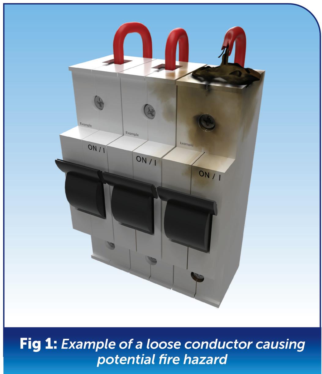
usually occur at the equipment and/or accessories within the cable connections, where the installer has been involved, as shown in Fig 1.
We all know that BS 7671 tells us that connections must be electrically and mechanically sound, but we also know mistakes can happen.
The importance of confirmation of correct torque tightening of terminals is essential, as both under- and over-tightening can result in the failure of the connections to equipment or accessories.
For this reason, it’s important that we follow Regulation 526.3 which stipulates that every connection shall be accessible for inspection, testing and maintenance.
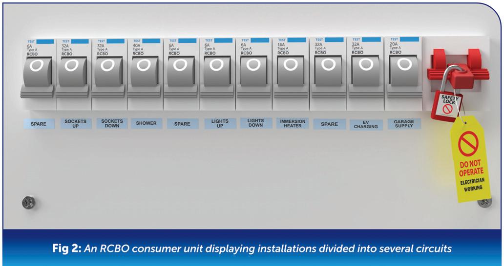
Designers can mitigate against the impact from faults. This can be achieved, as shown in Fig 2, by making sure we divide our installations into several circuits as per Regulation 314.1 indent (i), to avoid danger and minimise inconvenience in the event of a fault. In reality, however, the designer cannot entirely ‘design out’ the possibility of faults occurring.
There are also other factors that may lead to electrical faults in our installations, such as:
● Misuse
● Negligence
● Overuse
● Abuse
These factors can lead to faults in perfectly well designed and installed electrical systems and equipment.
We can reduce the risk of faults by ensuring that electrical
installations are looked after and well maintained. This may involve a systematic maintenance regime, such as a facilities management programme, or by carrying out regular inspection and testing.
The process of fault finding can seem daunting, especially to newly qualified electricians or trainees.
However, it doesn’t need to be if they adopt a methodical approach, understand electrical circuits and are competent in inspection and testing. At all stages of the fault finding process, we must work safely, and this will include safe systems of work such as safe isolation.
Fault finding can be broken down into simple steps using a ‘who, where, when and why?’ methodology.
The steps involved to successfully find a fault can be summarised as follows:
1. Identify the problem/symptom
We first need to identify what is actually happening. This could be as simple as a protective device that keeps tripping.
Once we’ve identified the problem, even at this early stage, we can start to formulate in our mind what the fault could be.
It’s always good to start with the obvious as there’s no point rushing in and dismantling the electrical installation if it isn’t necessary.
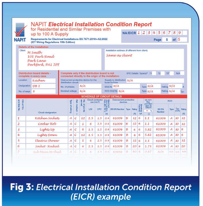
2. Gather information/evidence
At this stage, we can start to gather information and facts. Having good knowledge of the electrical installation and its associated circuits is essential, and this knowledge can come from a number of sources, such as:
● People (yourself, the client, the designer)
● Manufacturer’s instructions
● Drawings and circuit diagrams
● Circuit charts and schedules
● Previous test results
Fig 3 demonstrates these points using a sample EICR form.
3. Analyse the evidence
Once we’ve gathered the evidence, we need to analyse it in conjunction with carrying out standard tests and a visual inspection.
The cause of the fault may become obvious during a visual inspection, for example, water ingress into a piece of electrical equipment.
Standard testing is useful to back up any initial suspicions or to compare against previous test results.
4. Interpret information, inspection and test results
At this stage, we’re pretty much ready to diagnose the fault based on all the evidence and the test results.
Apart from very obvious problems that
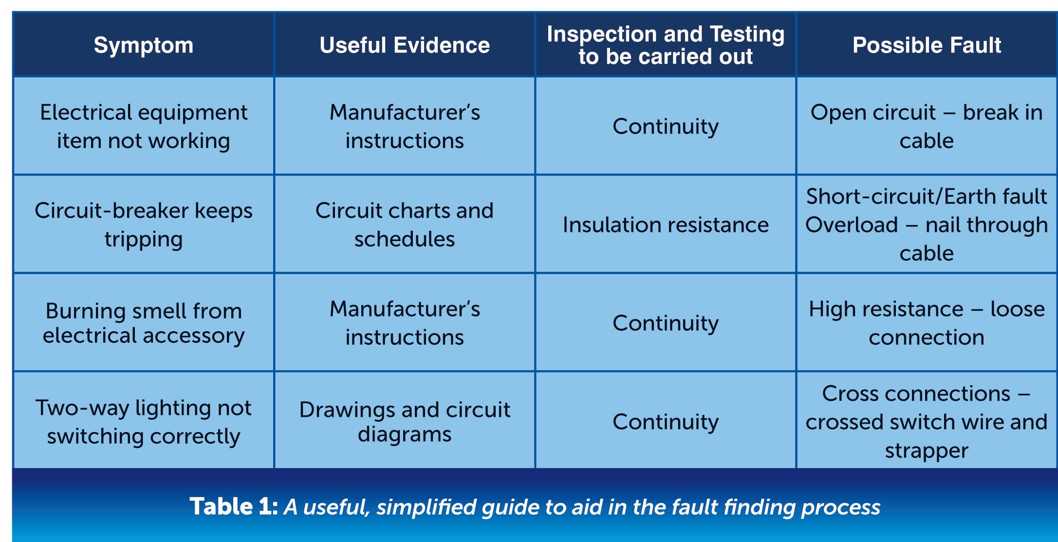
could be seen on a visual inspection or very complex faults, most faults generally fall into only a few categories, such as:
● Open circuit
● Short circuit
● Earth fault or leakage
● High resistance
● Cross polarity
It’s worth pointing out that you may encounter more than one fault on a particular electrical installation or circuit. However, it’s best to identify and rectify one fault a time. This will ensure you still maintain a methodical approach and don’t get confused during the fault finding process.
Table 1 is a simplified guide and can be used as a handy basic tool during the fault finding process.
5. Rectify the fault
Having established the fault, we’re now ready to rectify it. This may involve rewiring part of a circuit, replacing any defective electrical equipment or simply tightening loose connections.
6. Carry out functional tests
We need to check that the fault has been rectified. This will involve carrying out basic functional tests, such as switching equipment on/off.
It would be appropriate to carry out some standard testing, such as continuity, insulation resistance, earth fault loop impedance and possibly RCD tests and record the results to confirm the circuit is safe for continued use.
At this stage, it’s also good practice to show the client what you initially found (the fault, for example) and what you’ve done to fix it, including photographic evidence.
Conclusion
Fault finding is a task that most electricians will be required to carry out at one time or another. By adopting a methodical approach it can be less complicated and frustrating than you think and, ultimately, can be very rewarding. Although we ideally don’t want to encounter faults in our electrical installations, identifying and rectifying them provides us with valuable experience and builds our problem solving and fault finding skills.


Have you ever walked near high-voltage power lines and noticed a faint crackling noise accompanied by a mysterious glow around the wires? If so, you might have witnessed a fascinating phenomenon known as ‘corona discharge’.
While it might seem puzzling at first glance, understanding corona discharge can shed light on this intriguing occurrence.
Corona discharge occurs when the electric field surrounding a conductor, such as a power line, becomes intense enough to ionize the surrounding air.
This ionization process involves stripping electrons from air molecules, resulting in the formation of positively charged ions and free electrons. As these charged particles recombine, they release energy in the form of light, giving rise to the mesmerizing glow that surrounds the conductor.
This phenomenon is akin to the glowing aura seen around neon lights,
but on a much grander scale –picture the vast expanse of the sky near high-voltage power lines illuminated by this ethereal glow, a spectacle that captures the imagination and evokes a sense of wonder.
One of the most distinctive features of corona discharge is the faint glow or halo that appears around the conductor but the corona discharge can also produce an audible noise, described as a crackling or hissing sound, resulting from the rapid movement and recombination of charged particles.
Corona discharge typically occurs in high-voltage systems where the electric field strength exceeds a certain threshold.
As electricity flows through the power lines, the surrounding air molecules are subjected to intense electric fields, leading to ionization and the formation of corona.
This phenomenon is more pronounced during adverse weather conditions such as fog, rain, or snow, which can enhance
John Hayhurst, Electrical Tutor at City Skills SCC, explores the phenomenon of corona discharge near power lines.
the conductivity of the air.
Is it harmful?
While corona discharge itself is not necessarily harmful, it can have some effects on the surrounding environment and electrical infrastructure. The faint glow and crackling noise may be disconcerting to bystanders, but they are natural consequences of the operation of high-voltage power lines.
However, prolonged exposure to corona discharge can lead to energy losses in the transmission system and may cause minor degradation of insulating materials over time.
Conclusion
When you next hear a crackling noise or spot a faint glow near power lines, you can marvel at the phenomenon of corona discharge. Understanding the science behind this natural occurrence can help demystify the sights and sounds associated with HV electrical systems.
While corona discharge may seem mysterious, it’s simply a manifestation of the complex interplay between electricity and the surrounding atmosphere.


Jake Green, Head of Technical Engagement at Scolmore Group, considers some types of RCBOs and their applications, along with the relevant requirements of BS 7671.
Residual current operated circuit-breakers with integral overcurrent protection for household and similar uses, or RCBOs, are intended to protect people against earth fault current under the protective measure Automatic Disconnection of Supply (ADS), as well as additional

protection. RCBOs also provide protection against both short-circuit and overload.
The standard to which RCBOs conform is BS EN 61009-1 and the UK has a special national condition (SNC) whereby RCBOs providing protection for circuits having neutral conductors reliably at Earth potential are permitted to have an unswitched neutral; that is in the UK where the Earthing System is TN-S or TN-C-S RCBOs are permitted to be single-pole devices.
Difference between single-pole and double-pole devices
BS EN 61009-1 defines ‘pole’ as: ‘that part of an RCBO associated exclusively with one electrically separated conducting path of its main circuit provided with contacts intended to connect and disconnect the main circuit itself and excluding those portions which provide a means for mounting and operating poles together’.
Furthermore, BS EN 61009-1 defines
the ‘overcurrent protected pole’ as one which is, ‘…provided with an overcurrent release…’. The ‘switched neutral pole’ is given as ‘pole only intended to switch the neutral and not intended to have short-circuit capacity’.
Taking all definitions into account, it is important to recognise what this means when a manufacturer defines a product as single-pole (SP), single-pole and neutral (SP&N) and double-pole (DP).
● SP – a device having no connection point for the neutral conductor. The circuit neutral conductor will be connected to the common neutral bar. When the RCBO is switched on or off the neutral will remain connected in circuit and only the line conductor will open or close.
● SP&N – a device having a connection point for the line and neutral conductors and typically taking up two

ways on the distribution board. When the RCBO is switched on or off both the line and neutral conductor will open or close. However, the neutral connection will not have short-circuit capacity. Often the SP&N device switch will only have a single switch whereas the DP device will have a switch covering both poles.
● DP – a device having a connection point for the line and neutral conductors and will typically take up two ways on the distribution board. When the RCBO is switched on or off both the line and neutral conductor will open or close. The neutral connection will have short-circuit capacity.
Being a combination of circuit-breaker and RCD, RCBOs may be selected for use for both overcurrent protection and additional protection, and recognising the benefits of an RCBO as:
● Individual additional protection and control of final circuits,
● Easier to fault find,
● Less chance of unwanted operation.
The requirements of overcurrent protective devices used for protection against electric shock are detailed in Section 533 (531.2.1 refers). For TN systems such devices must be selected and erected to comply with Chapter 41 (531.2.2).
Except in certain conditions detailed in Part 7, it is worth noting that there is no requirement under overcurrent conditions to disconnect/switch the neutral in TT or TN systems (531.2.2.201).
current devices
The requirements for RCDs are detailed in Regulation Group 531.3.
Regulation 531.3.1 requires an RCD to disconnect all live conductors (line and neutral in a single-phase circuit). However, Regulation 531.3.1.201 permits single-pole switching where the neutral is in a TT or TN system (531.3.1.201); such systems being the most common type.
RCDs should be selected and erected to avoid unwanted tripping, and to this end Regulation 531.3.2 details six areas of consideration. Amongst other things, indent (i) allows for a split board with a suitable subdivision of circuits, and indent (ii) suggests the use of RCBOs will be beneficial in residential premises.
There are certain installations detailed in Part 7 where the general rules relating to overcurrent protection and RCDs are amended, and these will have an impact on the type of RCBO selected for use.
Section 708 (Electrical installations in caravan/camping parks and similar locations) requires all poles to be disconnected for all socket-outlets protected by an RCD. Under such cases the RCD/RCBO must not be single-pole (708.415.1).
where an RCD is supplied for additional protection (721.415.1).
Section 722 (Electric vehicle charging installations) requires all live conductors to be disconnected where an RCD is installed (722.531.3.1).
Section 730 (Onshore units of electrical shore connections for inland navigation vessels) requires socket-outlets to be individually protected by an RCD and disconnect all poles, including the neutral (730.531.3).
Section 709 (Marinas and similar locations) also requires socket-outlets to be individually protected by an RCD and disconnect all poles, including the neutral (709.531.2).
Section 721 (Electrical installations in caravans and motor caravans) requires all live conductors to be disconnected
It’s important to select for use the correct type of RCBO for the nature of the installation. There will be instances where single-pole devices will need to be replaced with either single-pole and neutral or double-pole devices.


Michael Peace CEng MIET MCIBSE, Senior Engineer at the IET, looks into the practicalities and requirements of BS 7671:2018+A2:2022 with respect to isolation and switching for mechanical maintenance.
The topic of heat-damaged shower pull cords was discussed on the IET EngX forum at the end of 2022, and not for the first time either.
During the debate, and to avoid the problem of heat-damaged isolators, it was asked whether isolators for equipment such as showers and ovens could be omitted and if it’s acceptable to rely on isolation at the consumer unit.
This article answers the debate by looking at the practicalities and requirements of BS 7671:2018+A2:2022 with respect to isolation and switching for mechanical maintenance.
What are the requirements for isolation?
BS 7671 is non-statutory but the Electricity at Work Regulations 1989 (EAWR) are written into law.
The EAWR are general in their application and refer throughout to "danger" and "injury". Danger is defined as "risk of injury" and injury is defined in terms of certain classes of potential harm to persons. Injury is stated to mean death or injury to persons from:
● Electric shock,
● Electric burn,
● Electrical explosion or arcing, or
● Fire or explosion initiated by electrical energy.
Regulation 12(1)(b) of EAWR states: "where necessary to prevent danger, suitable means shall be available for […] the isolation of any electrical equipment", where "isolation" means the disconnection
and separation of the electrical equipment from every source in such a way that the disconnection and separation is secure.
The main requirements for isolation and switching are provided in Chapter 46 and Section 537 of BS 7671:2018+A2:2022.
With respect to switching off for mechanical maintenance, the term isolation can be broadly split into three categories covering different parts of the installation:
1. Installation, 2. Circuits, and 3. Equipment.
Chapter 46 of BS 7671:2018+A2:2022 sets out the requirements for isolation and switching and Regulation 462.1 states that:
"Each electrical installation shall have provisions for isolation from each supply." This is provided in the form of a main linked switch or linked circuit-breaker located as near as practicable to the origin of the installation as a means of switching the supply on load, as set out in Regulation 462.1.201 of BS 7671:2018+A2:2022.
Regulation 462.2 of BS 7671:2018+A2:2022 requires every circuit to be provided with isolation for all live conductors, except those detailed in Regulation 461.2 of BS 7671:2018+A2:2022, which provides exceptions for TN-C-S and TN-S systems where the neutral or PEN conductor is reliably connected to Earth.
Equipment
Devices for isolation and switching or
plugs and socket-outlets can be used to provide isolation for equipment.
Note that for plugs and socket-outlets, isolation is achieved by withdrawal of the plug from the socket-outlet. The switch of a socket-outlet is not required to be suitable for isolation (see ‘(6)’ to Table 537.4 of BS 7671:2018+A2:2022).
Where mechanical maintenance may involve a risk of physical injury, means for switching off shall be provided in accordance with Section 464 of BS 7671:2018+A2:2022.
What are the requirements of BS 7671:2018+A2:2022 for switching off for mechanical maintenance?
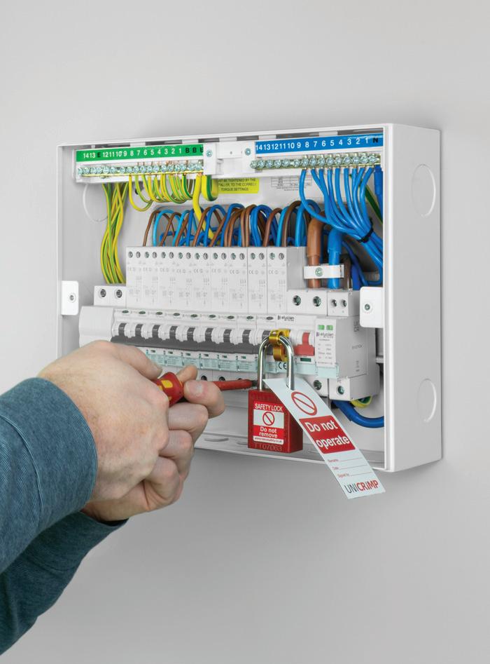
Regulation 464.2 of BS 7671:2018+A2:2022 requires suitable means to prevent equipment from being inadvertently or unintentionally reactivated during mechanical maintenance, unless the means of switching off is continuously under the control of any person performing such maintenance. This is typically an isolation device designed to allow a padlock to be installed to ensure safe isolation and prevent inadvertent re-energization.
Which devices are suitable for isolation?
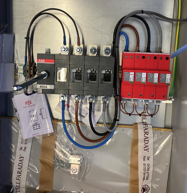
Table 537.4 of BS 7671:2018+A2:2022 provides guidance on protective, isolation
and switching devices and their suitability for isolation, emergency switching off and functional switching. This includes a wide range of devices from circuit-breakers to contactors.
Where protective devices are suitable and can be used for isolation of circuits, this is marked on the side of the device, as shown in the image below

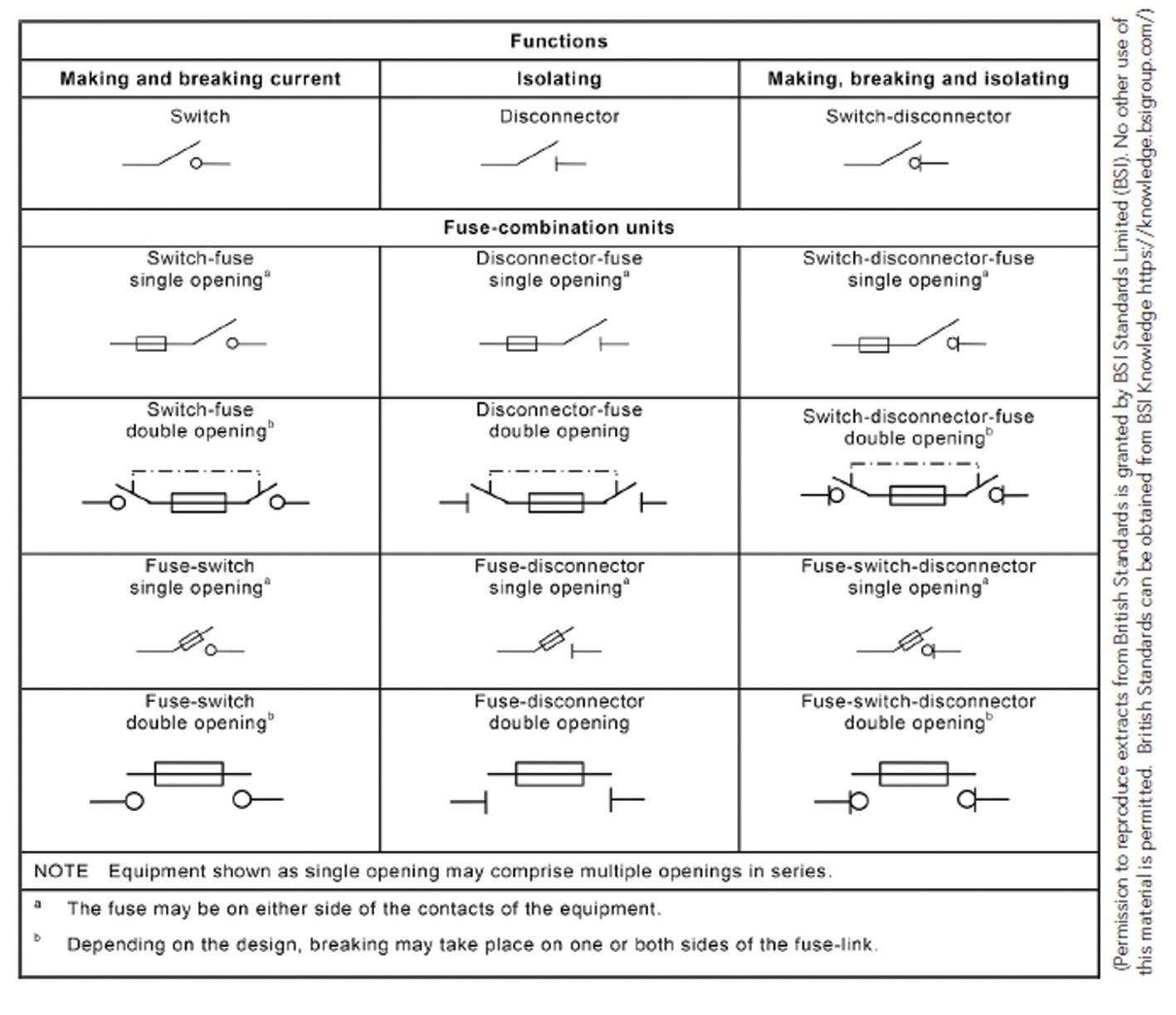
Table 1 of BS EN 60947-3:2015 provides a useful summary of the different types of equipment and definitions (see Fig 2)
Where should an isolator be located?
The isolator needs to be installed so that it is clearly identified by position or labelling. Regulation 537.3.2.4 states that: "Devices for switching off for mechanical maintenance shall be clearly identified by position or durable marking so as to be identifiable for their intended use."
"Identified by position" means, for example, if it can clearly be seen that the purpose of an isolator is for a particular piece of equipment. If it is decided to
locate the isolator away from the equipment for a particular reason, it shall be clearly identified.
Is it acceptable to isolate at the consumer unit for mechanical maintenance?
There is nothing in BS 7671:2018+A2:2022 to prevent isolation at the consumer unit for mechanical maintenance. The installation can be isolated by operating the main switch, as it is required to be a double-pole device suitable for switching the supply on load and as a means of isolation, in accordance with Regulation 462.1.201. The installation could be considered to be under continuous control or locked off if required.
The main consideration is the type of equipment connected and what is required in the manufacturer’s instructions. Frequently switching a high current inductive load is likely to reduce the lifespan of the protective device. It’s important to remember that the primary function is a protective device.
Then there are the practicalities to consider. For example, isolation at the consumer unit in a dwelling to carry out a maintenance task to replace equipment which takes 15 minutes once every five years may be acceptable. Whereas the isolation of an office block or house of multiple occupancy to carry out maintenance work on a more frequent basis will be more inconvenient and probably not acceptable.
Can I use a protective device for isolation?
Isolating an individual circuit as opposed to the whole installation using the main switch is more desirable as there is less inconvenience when others are using the installation.
The requirements for isolation and switching in TT systems are different to that for TN systems. For a TN-S system, where the neutral conductor can be considered to be reliably at earth potential, the neutral need not be disconnected, therefore it is permissible to use the protective device for isolation (see Regulation 531.2.2 of BS 7671:2018+A2:2022).
For TT systems, the neutral must be disconnected for isolation. This could be achieved by using double-pole protective
devices, but it is important to note that most readily available devices are single pole, therefore this method of isolation would not be suitable for TT installations. Whilst it is acceptable to use a protective device for isolation, it should be remembered that where protective devices such as circuit-breakers, AFDDs, RCBOs and RCDs are used, the primary function of these devices is protection and, as a consequence, they are not intended for frequent load switching. Where a protective device is used for frequent duty, the number of operations and load characteristics according to the manufacturer’s instructions should be taken into account. This is stated in ‘(5)’ to Table 537.4 of BS 7671:2018+A2:2022.
What do manufacturer’s instructions say?
Regulation 134.1.1 of BS 7671:2018+A2:2022 requires the installer to take account of manufacturer’s instructions. The advice provided in manufacturer’s instructions varies. Looking
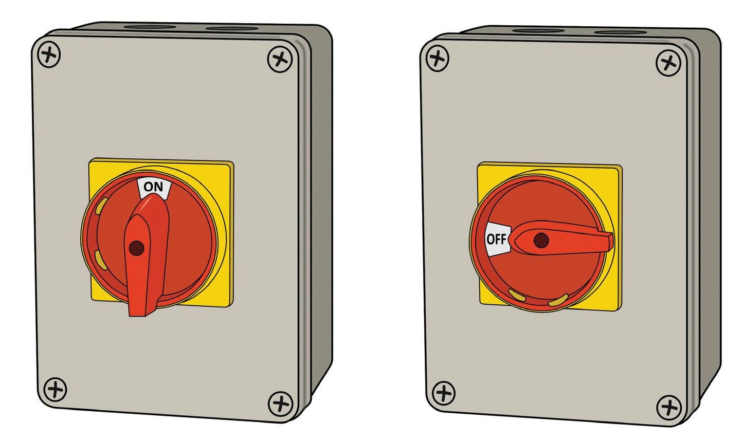
Switch off at isolating switch when not in use. This is a safety procedure recommended with all electrical appliances.
at the manufacturer’s instructions for a 10.5 kW shower, the general safety section states that a suitable double-pole isolation switch for supply disconnection must be incorporated in the fixed circuit in accordance with current wiring rules. At this point, it could be assumed that isolation at the consumer unit is acceptable but it’s important to read further.
The electrical installation section on page three of the manufacturer’s instructions recommends switching off at the isolating switch when not in use, as shown in Fig 3
Given the message that "this is a safety procedure recommended with all electrical appliances", it is difficult to see

how omitting a local isolator could be justified.
The example shown in Fig 4 is of manufacturer’s instructions for an extractor fan. It states that a double-pole fused spur having contact separation of at least 3 mm in all poles must be used and fitted with a 3 A fuse.
What do the product standards say?
The international standard for household and similar products is the IEC 60335 series. Clause 7.12.2 of IEC 60335-1:2020
i.Switch off mains supply before making electrical connections. If any doubt, contact a qualified electrician.
ii.These units are for fixed wiring only. A feasible cord must not be used. All wiring must be fixed securely and the cable to the fan should be a minimum of 1 mm2 in section. All wiring must comply with current I.E.E. regulations if outside the UK.
iii.A double pole fused spur having contact separation of at least 3 mm in all pole must be used and fitted with a 3 A fuse.
iv.The fan is double insulated and does not require an earth connection.
v.Fan should not be accessible to a person using either the shower or bath.
Household and similar electrical appliances – Safety – Part 1: General requirements states: “If a stationary appliance is not fitted with a supply cord and a plug, or with other means for disconnection from the supply mains having a contact separation in all poles that provide full disconnection under overvoltage category III conditions, the instructions shall state that means for disconnection must be incorporated in the fixed wiring in accordance with the wiring rules.”
Isolation at the consumer unit is permitted but it’s important to consider the practicalities and requirements of the manufacturer of the equipment. Where single-pole protective devices are used, consideration for the type of earthing system is required. Where protective devices are used for isolation, it is important to take account of the manufacturer’s instructions with regards to the number of mechanical and electrical operations. Manufacturers of electrical equipment often recommend the installation of device(s) for isolation and switching because turning off the equipment when not in use is a safety procedure recommended with all electrical appliances.
BROWSE OR
IN THIS REGULAR COLUMN, DR. TOM BROOKES, MD AT ZZEUS TRAINING AND CHAIRMAN OF THE FSA, ANSWERS YOUR QUESTIONS RELATED TO FIRE SAFETY. IN THIS EDITION HE LOOKS AT bs 5839-1 and whether it is safe to have just heat detectors fitted in hotel bedrooms.
The current rules in BS 5839-1 for a Category L2 fire detection and alarm system in hotels state that you may use a heat detector in hotel rooms that open onto escape routes and smoke detectors in the escape routes and corridors.
One of my customers (a risk assessor) has been told that because the Fire Safety Order requires that all relevant persons are adequately protected, the current heat detectors in bedrooms are incorrect and that smoke detection must be fitted in all hotel bedrooms.
Is this correct?
This answer has two parts, so I’ll answer the first question here: is it acceptable to install heat detectors in hotel bedrooms?
Using smoke detectors, which detect small particles, in hotel bedrooms is likely to increase false alarms. These could be triggered by steam from bathrooms and kettles, aerosol sprays, cigarette smoke, and other items guests might use.
More false alarms could lead to people mistrusting the fire alarm system, which might cause delays in responding to real alarms and lower
fire safety standards.
Heat detectors in hotel bedrooms offer some protection for guests when a fire starts. They alert hotel occupants well before a fire threatens any escape routes.
Fire statistics show that the chance of a fire starting in a hotel bedroom is very low (about one bedroom fire per million guest nights each year). There are almost no deaths in the room where the fire starts, no matter what type of detector is used in the bedroom.
We who sit on the BSI committee responsible for BS 5839-1 have not received any evidence that the current recommendations for hotels need to be changed.
BS 5839-1 guidance on using heat detectors in hotel bedrooms was confirmed by a specific decision from the government department in England and Wales (Chief Fire and Rescue Adviser).
This decision, called a "Determination in respect of the fire safety adequacy of fire detection in a hotel," supported the use of heat detectors in a particular hotel's bedrooms.
A link to the government determination is included here, should you need to justify to a risk assessor who may not be fully conversant with fire alarm categories:


www.gov.uk/guidance/determinatio ns-under-the-fire-safety-order#dete rmination-about-adequacy-of-fire-d etection-in-a-hotel
That said, specifying what category a fire system should be is often the fire risk assessor's job.
So, playing devil's advocate slightly, pretend this hotel specialised in individuals with movement issues or disabilities, or maybe was used as a respite speciality hotel where loved ones can go to a hotel that gives their partners a rest from the day-to-day care of the person with the issue.
With the majority of occupants likely to be elderly as well, most fire risk assessors would look at increasing the level of early detection to an L1 Category because the occupants may be unable to evacuate quickly in the event of a fire.

DO YOU HAVE A QUESTION YOU'D LIKE ANSWERED? EMAIL YOUR QUERIES TO: TOM@ZZEUS.ORG.UK
GET MORE DETAILS ABOUT ZZEUS TRAINING AND THE RANGE OF COURSES ON OFFER AT: WWW.RDR.LINK/EBF014

When designing any electrical installation, it’s important to consider the type of cable, the routing of the wiring system, as well as the method of protecting the wiring.
For new installations, providing the correct wiring system is selected, including any requirements for mechanical and additional protection, there shouldn’t be any issues in complying with BS 7671.
Chapter 52 covers the requirements on types of wiring systems and how they are to be installed. Section 522 looks at external influences, and while all of these can affect the wiring system, the one we need to consider here is the impact outlined in Regulation 522.6.
Part of Section 522 discusses the protection that is required for the appropriate parts of the wiring system.
Particular consideration is needed for any changes of direction of the wiring system and where such wiring enters any electrical equipment. So, when considering any such protection, it’s those parts of the wiring system that may be subject to damage from mechanical stress.

This Regulation details concerns regarding protection, and in particular impacts with the external influence category (AG), and has the requirement to minimise damage during erection as a result of mechanical stress caused by:
● Impact
● Abrasion
● Penetration
● Tension; and
● Compression
The important thing to remember is this requirement applies during installation, use or maintenance of the electrical installation, so factors have to be considered –not just during the installation stage, but for the expected lifetime of the installation.
As a result, such protection is required during the erection of the electrical installation in order to prevent any damage caused by any other trades working on the premises that can subject the wiring system to any of the previous categories listed under Regulation 522.6.
Within the electrical industry, it’s fundamental to have widespread
understanding of where cables can be installed within the prescribed zones to meet the requirements of BS 7671.
Unfortunately, other trades and clients may not have this knowledge or may be unaware of these zones.
It’s possible that this may lead to damage to the concealed cables when other trades install their equipment, enclosures and supports, often prior to the final fix and energisation of the electrical installation, resulting in unexplained faults.
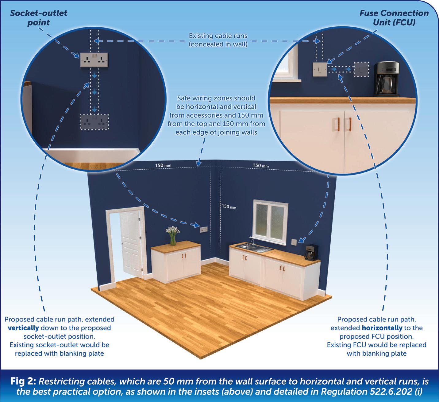
For domestic and similar installations, the cable types in use are Polyvinyl Chloride (PVC) insulated and PVC oversheathed cables in accordance with British Standard BS 6004. As they lack inherent mechanical protection, they must be positioned at least 50 mm away from any surface to avoid the risk of being penetrated by nails, screws and the like.
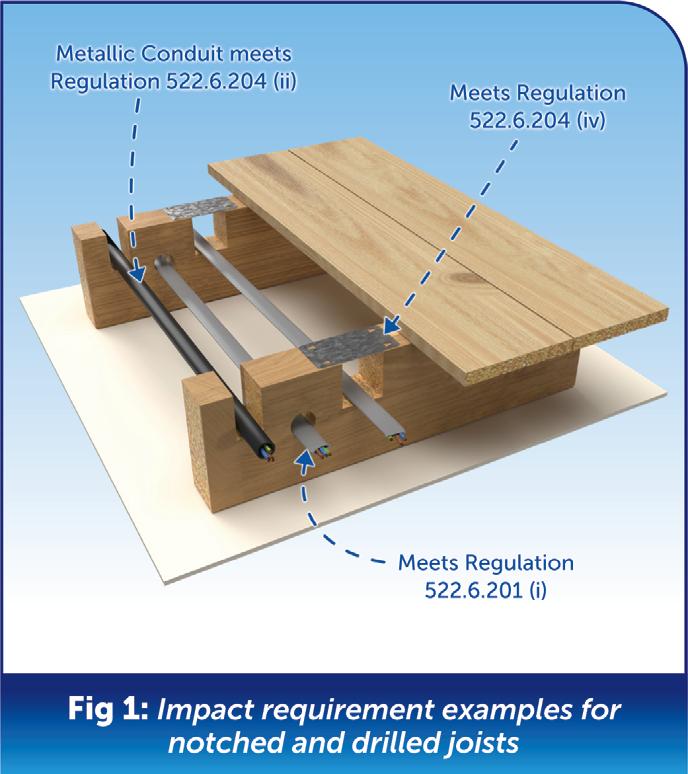
Where such cables pass through a joist within a floor or ceiling construction or under floorboards, they must be at least 50 mm from the top or bottom as appropriate to the joist or batten, as shown in Fig 1
There may be situations where similar unprotected cables are concealed within walls and partitions. It isn’t usually practical to provide such cables with earthed mechanical protection such as steel conduit.
For cables less than 50 mm from the wall surface, the most practical option is to restrict the run of cables to the prescribed zones horizontally or vertically to switchgear or accessories, as detailed in Regulation 522.6.202 (i) and as shown in Fig 2
Where access can be gained to the other side of the wall or partition, an indication of the location of an outlet point, and the possible position of cables from the reverse side of the partition, can be given by simply looking at the other side prior to carrying out the drilling or
cutting into the wall or partition.
Installing a socket-outlet on one side of the partition and a blank plate on the reverse side is another option. Although not always practical, this gives a clear indication that cables may have been installed vertically or horizontally to such points on both sides of the wall or partition.
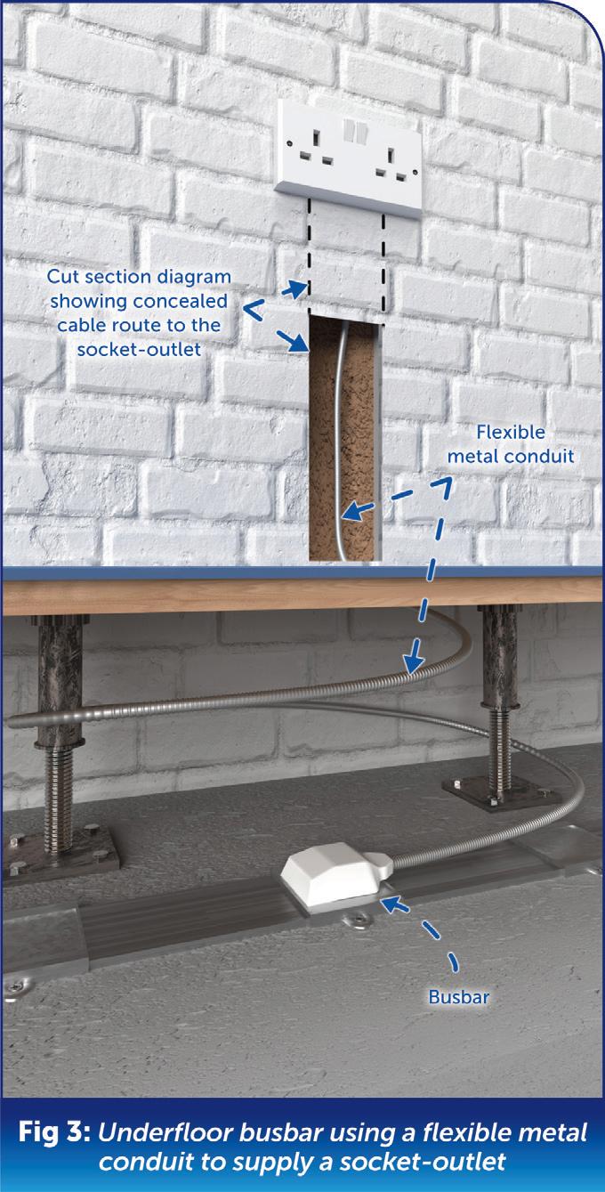
In some commercial installations, prewired metal flexible conduit is being utilised either from under floor power tracks or direct from the Distribution Boards as a means to reduce installation times.
While this type of wiring has its advantages, if the location in which it is installed fails to comply with a depth of more than 50 mm or is installed in metal partitions, then Regulation 522.6.202 is applicable (see Fig 3)
This Regulation requires that the cable concealed in the metal partition wall must be additionally protected by a 30 mA RCD or it must be mechanically protected in accordance with Regulation 522.6.204.
The requirement in Regulation 522.6.204, which relates to conduit, is contained in item (ii). This refers to earthed conduit which satisfies the requirements of BS 7671 for a protective conductor;
however, flexible metal conduit cannot comply with this particular requirement.
As a result, unless mechanical protection is provided for the flexible metal conduit by some other means to prevent penetration of the cable by nails, screws and the like – such as that referred to in item (iv) of Regulation 522.6.204 –the use of flexible metal conduit alone cannot comply with the requirements of Regulation 522.6.204.
In areas where there is a higher potential of damage from impact from either medium severity (AG2) or high severity (AG3), protection shall be provided by one of the following:
● Mechanical attributes of the wiring systems (or)
● Location of the wiring system (or)
● Provision of additional local or general protection (or)
● Any combination of the above.
Concealed cables in existing electrical installations
It’s one of the main dilemmas associated with the addition or alteration of existing electrical installations where there is the
danger of penetrating concealed cables, leading to a risk of fire or electric shock.
Concealed cables that are not protected are susceptible to damage due to penetration by nails, screws and other sharp objects.
Although concealed cables have had requirements for installation within safe zones and/or mechanical protection or additional protection in the form of an RCD since the 16th Edition of BS 7671, there are a multitude of premises with hidden cables without appropriate protection or routing in the correct zones.
It’s always prudent to check accessories or equipment for expected routing of cables and to use a cable detector if there’s any suspicion of concealed cables.
When considering the design of an electrical installation it’s important to take into account the proposed cable routes and the potential dangers of penetrating concealed cables.
What fuse do you need for a Type 1 SPD? Robin Earl, Market Development Manager at DEHN UK, provides some answers and warns about deviating from established norms.
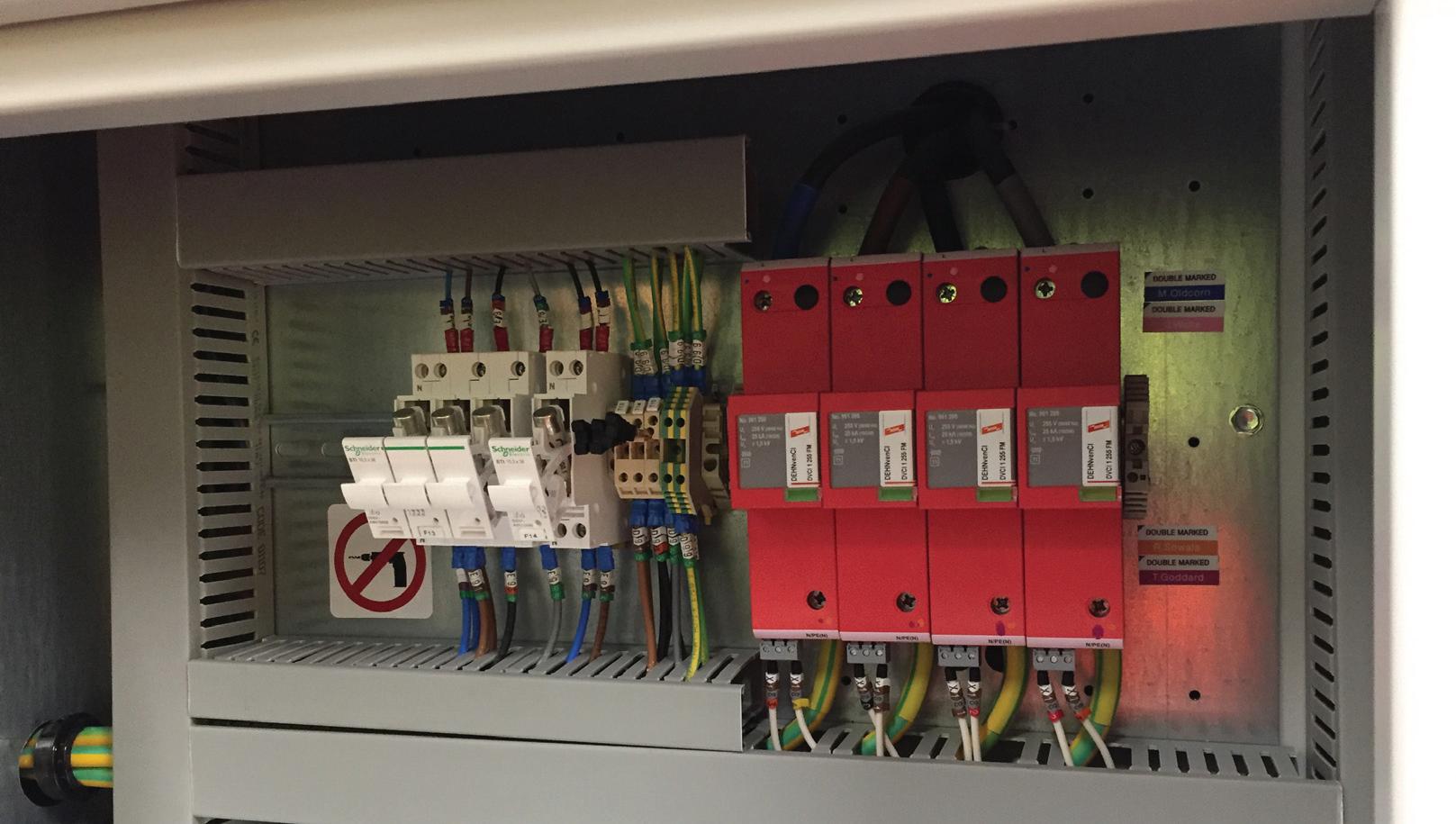


Tbe found in the installation guide provided with the product. However, some contractors, for whatever reason, still want to deviate from the published guidance, so any change needs to consider the following.
The Type 1 SPD has three different types of current that can flow through the circuit:
1. The lightning impulse current (Iimp). This is what the SPD diverts to ground during lightning events.
2. The short circuit value in cases of a fault at the location of the SPD. This is called short circuit interrupt (Isccr).
3. For spark gap Type 1 SPDs there’s a third value to consider –the line follow current (Ifi).
As an example, for the top of the range DEHNventil, a combined type 1/2/3 SPD, the lightning current value is 25 kA per pole for a total of 100 kA for all four poles.
The short circuit value and the line follow current are rated as 50 kA each.
Any deviation from the specified fuses, which in the case of the DEHNventil is 250A gL/gG, needs to take account of all those values.
The most requested deviation from the specification is to ask if an MCB is okay in the Type 1 SPD circuit. MCBs typically have a breaking capacity of between 10-15
We’ve seen what happens to MCBs after a lightning strike, it is not good. We’re aware that MCBs have different ratings, for example to BS EN 60898 the rating is 10 kA and to BS EN 60947-2 it’s now 15 kA, but still not 25 kA. Using a D curve MCB will not alter anything.
If the MCB is the overcurrent protection device (OCPD) in the surge circuit, then the MCB during the act of being blown apart will remove the SPD from the role of an overvoltage protection device. As the SPD is in a parallel circuit, power is maintained to the installation, so the next surge will not be diverted to earth as the SPD has been removed, and further damage will happen.
We also get asked about using MCCBs as they can have rupture capacities beyond 25 kA. We cannot forget the short circuit interrupt value as well as the lightning impulse and we find that most MCCBs will fail one or the other during tests.
The MCCB may not be fully destroyed by the tests, but it can trip and isolate the SPD. Again, the installation will remain energised, but protection has been removed.
Finally, we get asked about any other fuse type apart from the gG/gL, and as for the other OCPDs types listed previously, if we have not tested it and its not on the
are asked, and it’s mainly in retrofit situations where there’s a panel board feeding the SPD via a MCCB or fuse and this is the simplest solution that presents itself. Alternative solutions could be a different way to break out of the board via feed thru terminals replacing the MCCB or using an isolator.
Another solution could be the Type 1 SPDs that have built-in fuses as per the DEHNventCI. Then the installation just needs the connection to the phase bars with or without a dedicated surge circuit isolator.


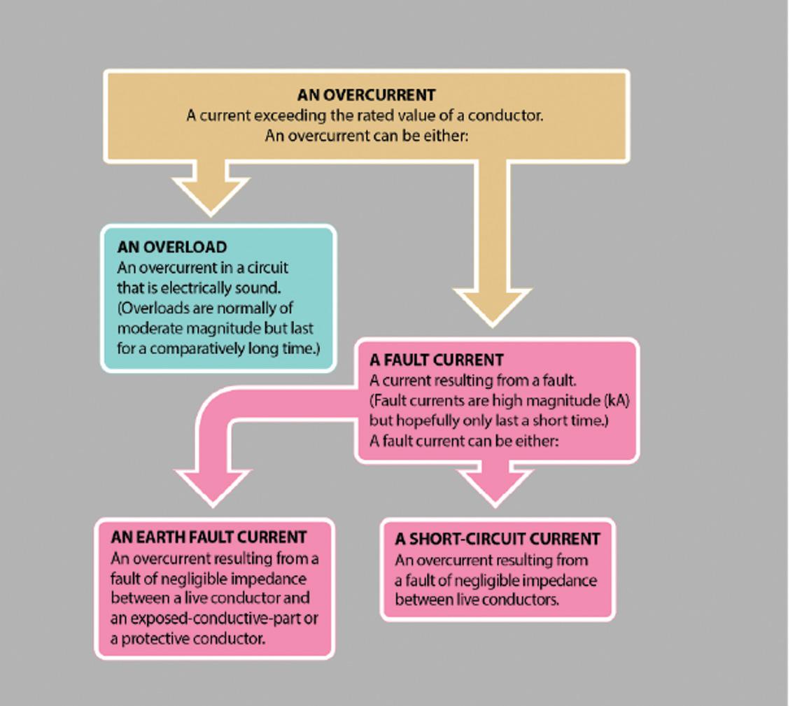
Part 2 of BS 7671, defines an overload current as being ‘An overcurrent occurring in a circuit which is electrically sound’. An overcurrent may result from ‘overworked’ electrical or electro-mechanical equipment, or by users inadvertently or deliberately connecting equipment such that the current exceeds that which the circuit was designed to carry.
Fig 1 identifies the relationship between the different conditions that may cause an overcurrent. This article will only
consider overload conditions.
It should be remembered that not all electrical loads are liable to overload. Loads that are typically resistive in nature, including electric showers, immersion heater elements, instantaneous water heaters, convector heaters and the like, are unable to draw more than their rated current. In such cases, a device providing protection against overload need not be provided (433.3.1 (ii)).
However, where individual loads that
This article from the experts at NICEIC gives an introduction into overload current and how the requirements for this in BS 7671 are to be applied. It aims to assist contractors to make informed decisions during the design stage of an installation.
are inherently not liable to overload are connected to a circuit, such as a ring final circuit, that circuit can be subjected to overload.
All circuits, whether they are liable to overload or not, must be protected against fault current, with a few exceptions (434.3).
Ring final circuits may be considered as a special case, in which to minimise the risk of overload, regulation 433.1.204 details particular conditions that need to be applied, including:
● socket-outlets and accessories must be manufactured to BS 1363 and supplied through a ring final circuit with or without unfused spurs, protected by a 30 A or 32 A protective device;
● the circuit must be wired with copper conductors having line and neutral conductors with a minimum cross-sectional area (csa) of 2.5 mm2 (where 2-core mineral insulated cables conforming to BS EN 60702-1 are used, a csa of 1.5 mm2 is permitted);
● the current-carrying capacity (Iz) of the cable, when corrected for the particular installation conditions must not be less than 20 A;
● the load current in any part of the circuit should not exceed the current-carrying capacity of the cable for long periods.
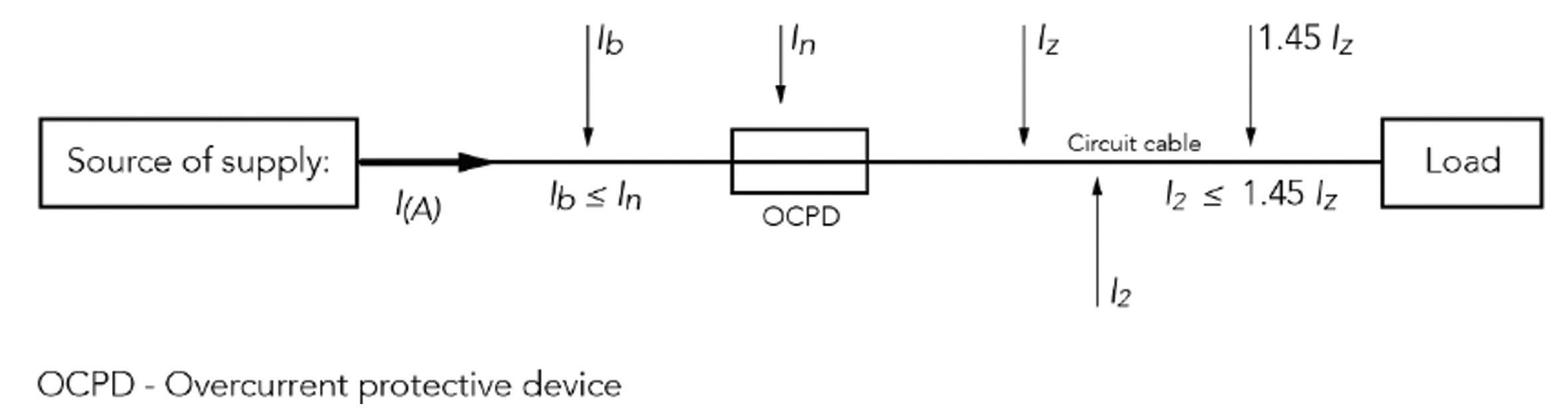
Coordination between conductor and overload protective device
Fig 2 outlines a typical circuit, indicating the overload protective device (normally a circuit-breaker or fuse), the circuit conductors (cable) and the load.
When an overload occurs, the protective device is designed to automatically disconnect the circuit by means of the circuit-breaker tripping or fuse rupturing.
Should an overload occur in a circuit where there is no overload protection provided, the temperature of the circuit conductors is liable to increase significantly which, over time, may lead to damage of insulation, joints and terminations of the conductors and/or their surroundings.
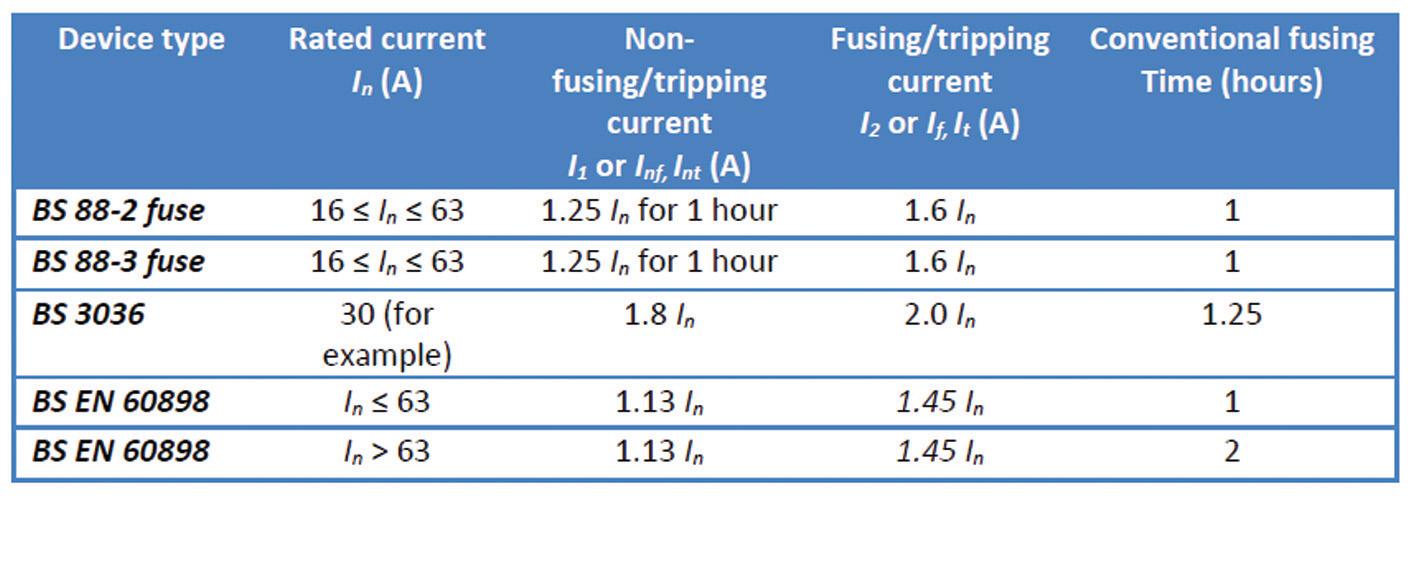
To protect against any such thermal distress, the circuit design must properly coordinate the current-carrying capacity of the conductors and the anticipated load current with the characteristics of the overload protective device (see Table 1).
With the exception of rewireable fuses to BS 3036, where the operating characteristics of a protective device meet the requirements of 433.1.1, as reproduced in the following expressions (i) & (ii), protection against overload will be provided:
● Expression (i): Ib ≤ In ≤ Iz
–The design current of the circuit (Ib) must be less than or equal to the current rating or current setting of the protective device (In), which must be less than or equal to (Iz), the lowest current-carrying capacity of the conductors forming the circuit.
● Expression (ii): I2 ≤ 1.45 Iz
–The current causing effective operation of the protective device (I2) must not exceed 1.45 times the lowest of the current-carrying capacity (Iz) of any of the conductors of the circuit.
Expression (i) is self-explanatory. However, it is worthwhile considering what expression (ii) means for the designer.
Where:
In – value of current that the protective device can carry continuously without deterioration under specified conditions.
I1 – value of current specified as that which the protective device is capable of carrying for a specified time (conventional time) without operating.
I2 – value of current specified as that which causes operation of the protective device within a specified time (conventional time).
As an example, consider a user replaceable 16 A gG fuse to BS 88-3 (BS HD 60269-3) states that:
● non-fusing current I1 is 1.25 In (1.25 x 16
= 20 A) for 1 hour, and
● fusing current I2 is 1.6 In (1.6 x 16 = 25.6 A).
Cable manufacturers must ensure that PVC or XLPE insulated cables can safely withstand overload currents up to 1.45 times their continuous current rating without showing any indication of deterioration. Therefore, expression (ii) would be satisfied if, for a 16 A fuse, 1.6 In ≤ 1.45 Iz
Using the same 16 A fuse, a short-term overload of 20 A (1.25 In x 16 A) could be sustained for 1 hour, after which time the fuse element will weaken and break. If during this process the overload was to increase to 25.6 A (1.6 In x 16 A), the fuse would rupture within the hour without causing any undue stress on the cable or associated equipment.
Additionally, where a protective device, meeting one of the standards in regulation 433.1.201 is installed, compliance with the expressions (i) and (ii) will also result in compliance with indent (iii) of regulation 433.1.1.
Location of overload protective devices
In general, and except where regulation 433.2.2 or 433.3 apply, a device for overload protection is required at the
point where a reduction occurs in the current-carrying capacity of the conductors of the installation (433.2.1).
If there are no outlets or spurs after the reduction in cross-sectional area, the protective device may be installed along the run of that conductor provided that:
● Protection against fault current is provided (434), or
● The length of run before the overload protection device does not exceed 3 m, and the circuit is installed in a manner that reduces to a minimum the risk of:
● a fault, and
● fire or danger to persons (433.2.2).
Except where a location presents a risk of fire or explosion, overload protection need not be provided:
● For a conductor,
● on the load side of a point where a reduction in the value of current-carrying capacity occurs if
the conductor is effectively protected against overload by a protective device installed on the supply side of that point, or
● which, because of the characteristics of the load or the supply, is not likely to carry overload current.
● Where the DNO agrees that their cut-out(s) provide(s) overload protection between the origin and the main distribution point of the installation (so long as overload protection is provided at that point) (433.3.1).
Overload protection can also be omitted for safety reasons, where unexpected disconnection of supply could cause danger or damage (433.3.3).
An overload may be considered as an overcurrent occurring in a healthy circuit resulting from overworked electrical equipment, or as a consequence of the connected load exceeding the current that the circuit was designed to carry.
To prevent thermal distress and damage to the circuit conductors, the protective device is designed to automatically disconnect the circuit in the event of an overload. As such, any circuit design must properly co-ordinate the current-carrying capacity of the conductors and the anticipated load current with the characteristics of the overload protective device.
Electrical loads such as electric showers, immersion heaters, convector heaters and the like typically have resistive characteristics and are unable to draw more current than their current rating and are therefore unable to overload. In such cases, a device providing protection against overload need not be provided. However, where individual loads that are inherently not liable to overload are connected to a circuit, such as a ring final circuit, that circuit can be subjected to overload.


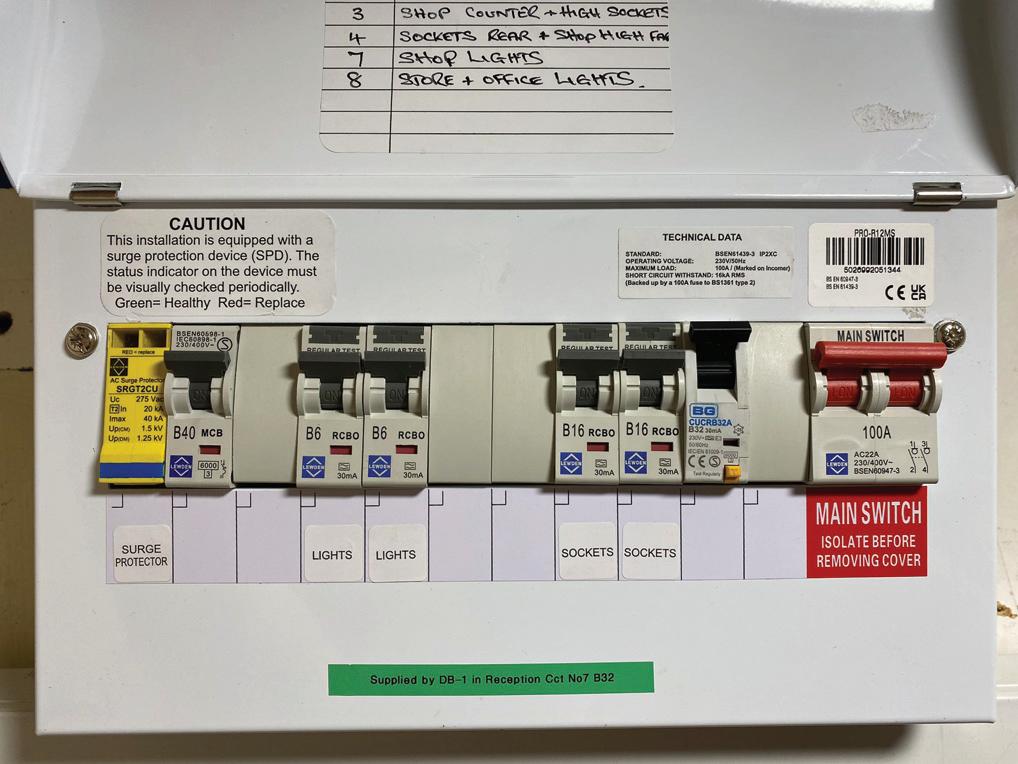
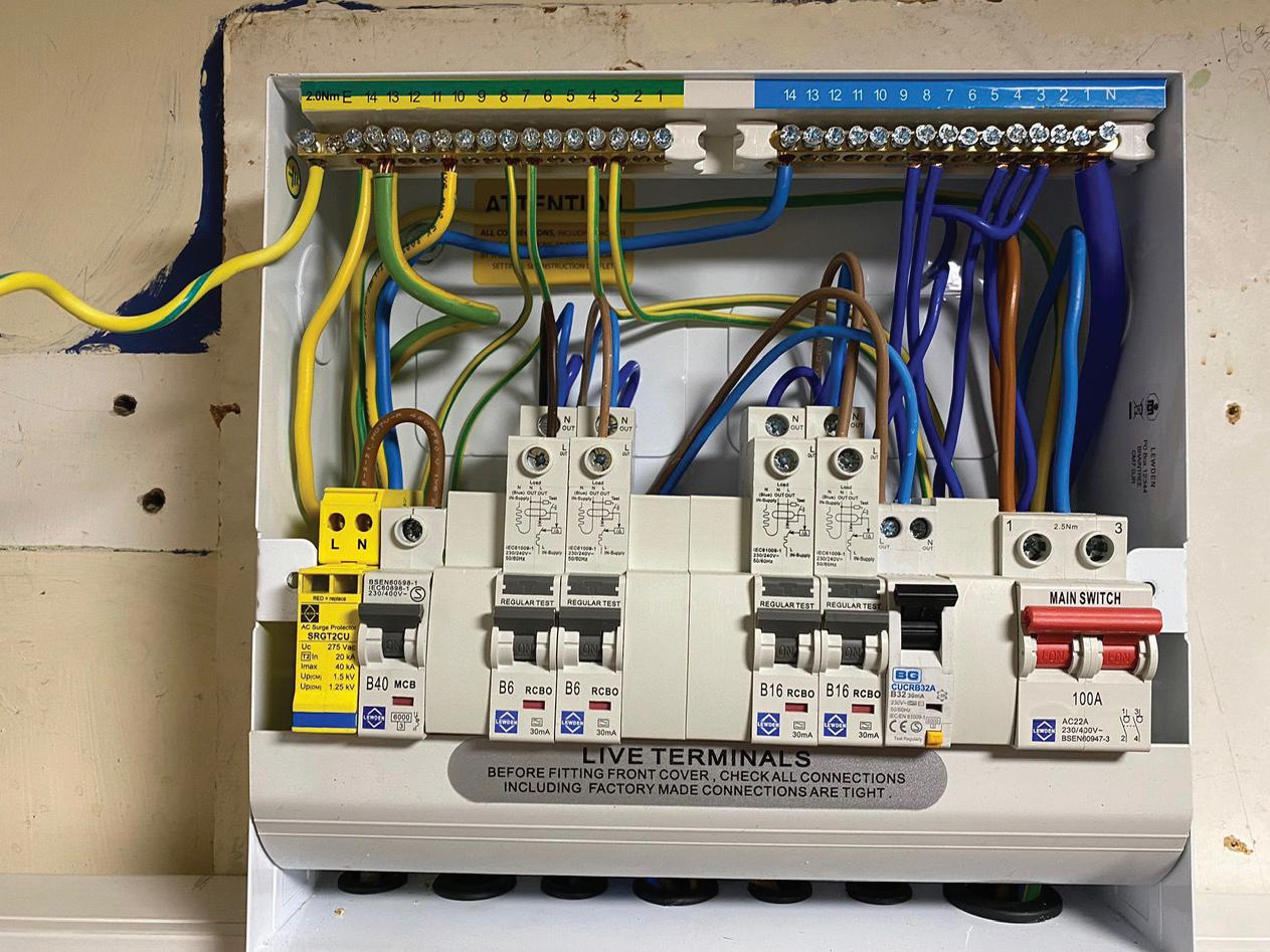
It is extremely frustrating when you are conscientious and compliant with the requirements of BS 7671, show good workmanship and have pride in the quality of work only to find someone has tampered with your finished installation.
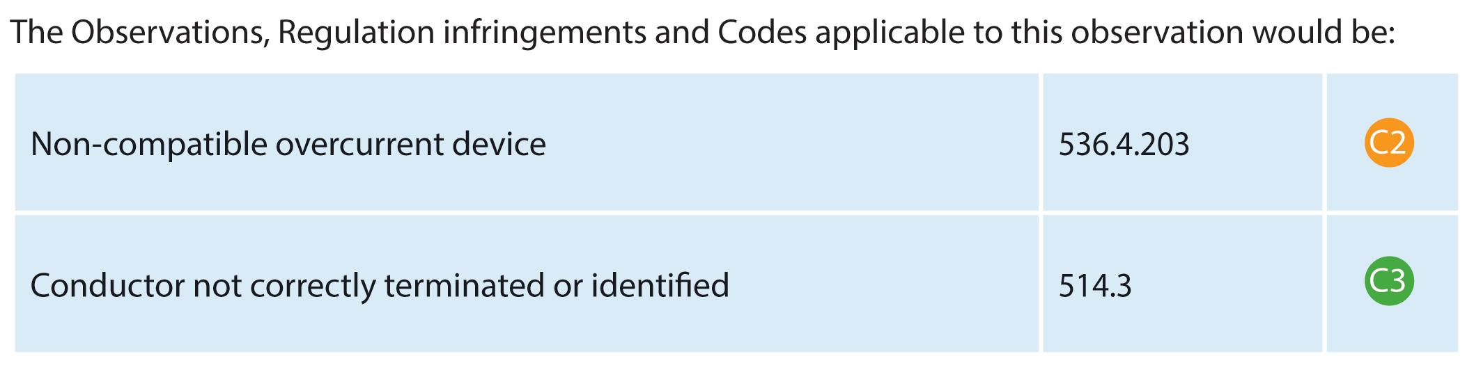
With this addition to a Distribution Board for a new circuit the culprit has installed an RCBO of a different manufacturer to the DB and the other devices. The requirements of BS 7671, and in particular Regulation 536.4.203, requires an assembly such as a Distribution Board to have devices that are declared
as suitable.
Due to the type testing of devices in such an assembly the manufacturer would not be able to carry out product testing on devices that are not within its own product range.

Within the Distribution Board the circuit protective conductor (cpc) of the new circuit in way 2 has not been connected in corresponding terminals where the cpc is in way 11. Therefore, the classification code would be a potentially dangerous C2 incompatible overcurrent and RCD protective device.


Updated for BS 7671:2018+A2:2022, NAPIT’s EICR Codebreakers publication is purpose-written to aid contractors, inspectors and clients, and now includes updates to align with Amendment 2 of the IET 18th Edition Wiring Regulations. The book is the perfect technical aid for electrical professionals and their customers.


Need help with cracking those all-important EICR codes? Every month the technical team at NAPIT will be studying your latest ‘Caught on Camera’ photos and offering advice on the next steps, should you find a similar installation. If you want the team at NAPIT to help crack your codes then send your pictures through to us at: pe@hamerville.co.uk


While BS 7671 is for fixed electrical installations, not portable appliances, where we come across these types of dangerous situations with immediate risk of electric shock when carrying out an EICR we have a duty to report to the client and take steps to remove such a danger.
The damaged plug top exposed the live parts of the fuse terminals and would attract a classification code C1. This is simple to rectify by switching off the plug top at the socket-outlet, removing the plug top and cutting the plug top from the flexible cable.
The decorator may not be best pleased, but everyone has a duty of care when in the workplace and should not place any other trades in danger.
The other issue due to ongoing work is the open hole in the plasterboard above the socket-outlet which can allow access to live parts, permit dust and debris entering the terminals of the socket-outlet. While work is being carried out on or near live electrical systems these have to remain safe for those working in the vicinity, including any temporary supplies that may be required.
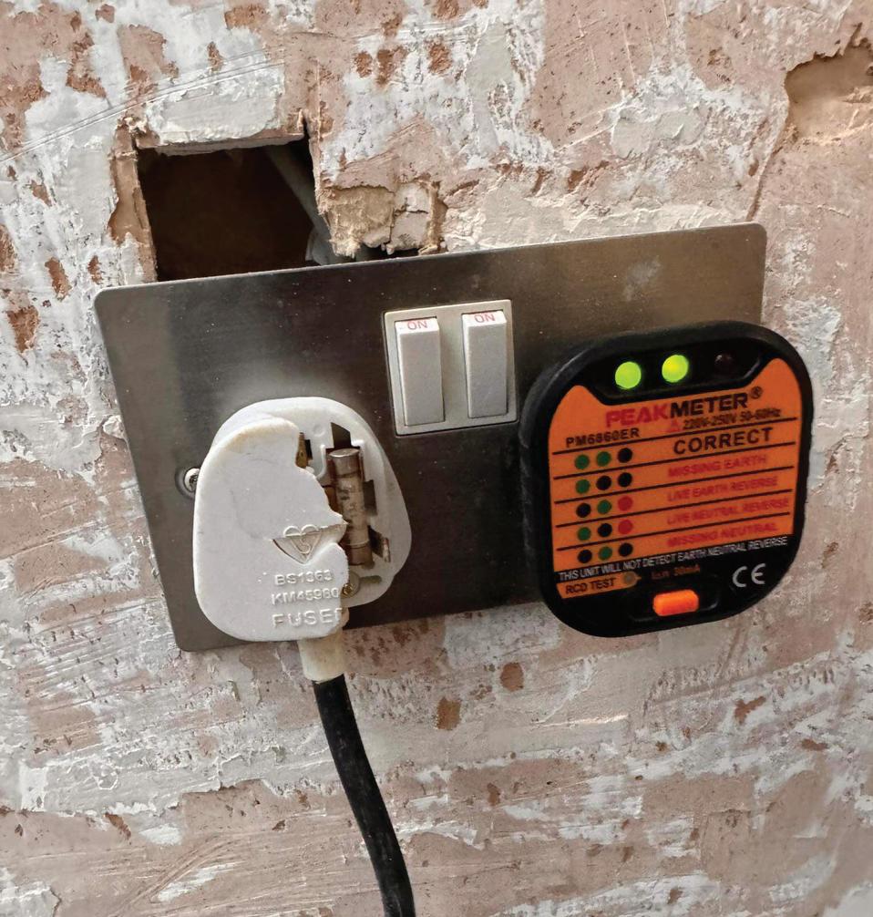

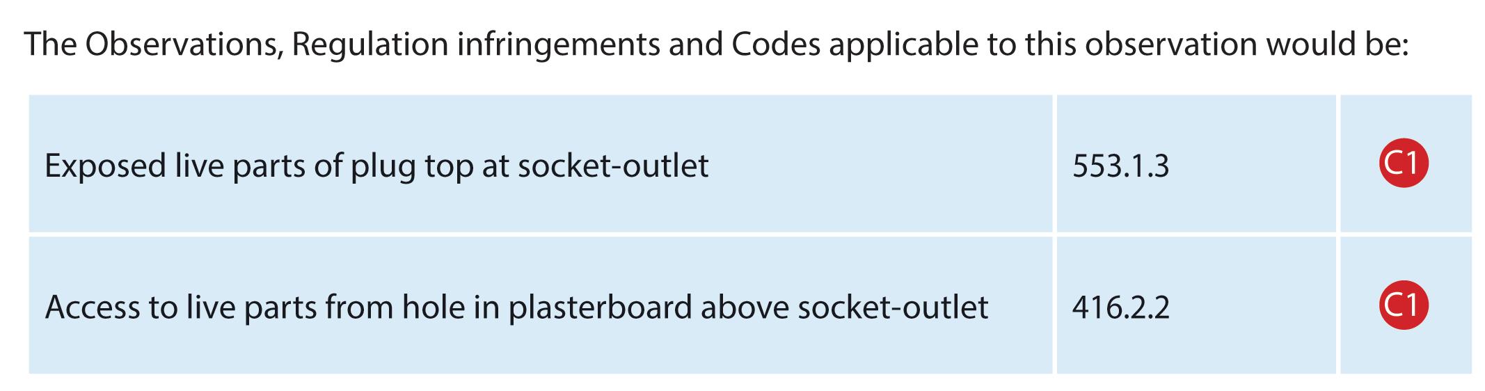

Therefore, the classification code would be a C1, Danger present -Risk of Injury, for exposed live terminals of the plug top. Additionally, the socket-outlet could also attract a C1. ORDER YOUR COPY OF NAPIT CODEBREAKERS BY
The A2:2022 18th Edition Codebreakers publication is priced at £22.00 (members) and £24.00 (non-members). It is available in both hard copy and digital versions * Price is VAT exempt and excludes postage and packaging.


Geoff Meads, Network School Trainer for CEDIA, looks at how networks are configured and operate and explains why they’re the bedrock of a quality smart home installation.
When you think about a ‘smart home’, what do you imagine? Maybe it's a huge property with fancy lights, piped music, and a TV in every room?
Perhaps there’s a sophisticated security system and curtains that open and close automatically?
Even the most modest view of a smart home might include a video doorbell, wireless speakers and maybe a ‘smart’ thermostat.
Whichever type of installation comes to mind, it will have one common technology as its backbone – an IP network.
Once only found in the world of corporate IT systems, the IP (Internet Protocol) network found its way into homes with the introduction of internet access in the late 1990s. For many people, it’s just known as ‘the Wi-Fi’, an anonymous black box in the corner of a room downstairs or by the front door.
Nowadays, a huge amount of pressure is put on this little black box, especially with the introduction of mobile devices and internet-based TV systems like Netflix, YouTube and BBC iPlayer.
Because home networks are now so ‘busy’, venturing into smart home
technology without IP networking knowledge is like trying to do electrical work without knowing your ‘twin and earth’ from your RCD. You might be able to make a guess as to how it all works, but disaster won't be far away without a bit of education underpinning your work.
What
So, what is an IP network? We can think of a network as an interconnected collection of devices. However, unlike simple point-to-point connections like traditional audio and video cables, network connections are different: they offer two-way communication, they split transmissions up into smaller chunks (rather than a continuous stream of data) for transmission, and information can travel through many other devices before reaching their destination.
The way network traffic moves can be understood by looking at the patterns that devices form when they’re connected together.
First is a ‘bus’ network. Just like busses on roads,
data can be exchanged along a common ‘road’. The ‘road’ can be a cable but, in modern times, the most common bus network is Wi-Fi, which uses the air around us as the ‘road’.
The second pattern we find is called a ‘star’ network. Much like a roundabout, a star network uses a single, central point to bring several roads together, so traffic might move from one road to another in order to reach its final destination.
Finally, we have a ‘mesh’ network. These are a little more complex, as each device has multiple incoming and outgoing connections. A full explanation of a mesh network is beyond the scope of this article but is covered in many network courses.


When splitting each transmission into small, more manageable chunks, (in network terms we call them ‘Packets’), the reliability of transmission is increased. Also, network protocols allow for the notification and resending of missing or damaged packets, meaning a network can guarantee message integrity.
Network devices exchange data with each other using addresses. Each component has an ‘address’ much like each building does in the world around us. The addresses for both sender and destination are added to every packet being sent, such that any device dealing with a packet en-route between origin and destination knows where the packet is destined for and who sent it, in case of problems!
Key network components
The foundation of any network is what we call its ‘physical layer’. This means the physical pathways that connect devices together. These are normally formed from one of, or a combination of, three types: electrical signals via Ethernet cables (typically Cat5e or Cat6); Wi-Fi (using electromagnetic waves through the air) and light pulses, using fibre-optic cables. In order of decreasing bandwidth, the best option is fibre-optic, then Ethernet cables and finally Wi-Fi, which offers the
lowest bandwidth/network speed.
Hardware network devices can be split into two types. Firstly, we have ‘infrastructure’ devices. These are the pieces of hardware that form the network itself and allow packets of information to move around.
The most important infrastructure device is called a ‘router’. Just about everyone has one of these at home already. You might have a BT Homehub, Virgin Hub or other device that came free from your internet service provider and that is, in its most basic form, a router.
You might also have a ‘switch’. These allow you to connect more than one or two wired network devices. Finally, we have ‘Wireless Access Points’ (WAPs). These provide a wireless connection into the network using radio transmissions.
Typically, the router you have at home will have a WAP built in, but these rarely provide enough coverage for a whole home unless it's a smaller house with only a few occupants. To extend Wi-Fi coverage, we can add more access points around the house and connect these back to the router using ethernet cables.
The second group of devices is called ‘client’ devices. They operate on the end of network connections and are the things humans interact with. Here, we find smart phones, laptops, televisions, security cameras and a myriad of other devices.

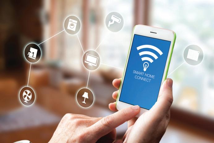
deliver data to phones, TVs, computers, etc. The potential market is huge!
However, like learning any new technology, you’re best placed if you start at the beginning. Learning from first principles not only sets you up to design and install networks that will work well and be reliable in the long term, but also means you’ll be able to fault-find more quickly if things go wrong.
The ideal route for new starters CEDIA’s suite of ‘Network School’ courses are ideally positioned for new starters in networking. They begin assuming zero knowledge on the part of the student and build a level of understanding that allows new engineers to approach networking from a fully professional starting point.
If you just want to ’dip your toe in the water’ then the one-day ‘Residential Networking’ class is the ideal starting point. It includes basic connectivity, setup, and configuration of basic network hardware to the level required for an installation in a basic family property.
Further courses in the CEDIA network pathway explore advanced configurations, remote access, and a deep dive into more sophisticated Wi-Fi setups too.
If you're thinking of learning more about networking and adding it to your offering, there’s good news –every house needs a network to


Wiring systems must be selected and erected to avoid during installation, use and maintenance, damage to the sheath or insulation of cables and their terminations (522.8.1). Jake Green, Head of Technical Engagement with Scolmore Group, takes a look at suitable means of cable support for a variety of circumstances as well as the requirements of BS 7671.
All cables and conductors must be supported in such a way that the level of mechanical strain which naturally exists will not cause either the cable/conductor or the terminations to be compromised (522.8.5).
Furthermore, all cable supports and enclosures shall not have sharp edges liable to damage the wiring system, and cable/conductors are not to be damaged by the means of fixing (522.8.11 & 522.8.12). It’s important, therefore, that care is taken when selecting for use supports that are appropriate for the cable/conductors.
Types of support
There’s a wide range of options available for the contractor when selecting cable supports. These include, amongst other things:
● Cable ties
● Cable cleats
● Cable clips
● Cable tie accessories
● Cable glands
The type of fixing will depend on the nature of the surface to which the support is fixed. For example, cable ties would be suitable for fixing cables installed on basket tray or cable tray, whereas cable clips would be suitable for wooden surfaces.
Similarly, the type of support will depend on the type of cable being installed. For example, cable cleats will be suitable for steel-wire armoured cables.
The guidance issued within the On-Site Guide (OSG) published by the IET is helpful in deciding on the nature of cable

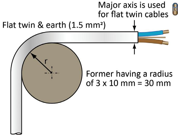
support and the distances recommended between clips. Appendix D covers cables generally, specific applications such as caravans and the like, overhead wiring as well as conduit and trunking support.
Table D1 details spacings of supports for cables in accessible positions. Fig 1 gives an example of the recommended distance between clips for a cable having a diameter not exceeding 9 mm, based on Table D1. As the cable diameter increases, the distance between clips is permitted to grow.
Whilst the support distances are important, it remains the case that the purpose of cable supports is to ensure there’s no undue strain on the cable or its terminations.
Similarly, when cables are bent it’s important that there’s no undue strain on the internal conductors caused
when the bend is too tight (522.8.3).
Fig 2 shows an example of the recommended bending radius for 1.5 mm 2 insulated and sheathed ‘twin and earth’ (Table D5 OSG).
Two issues must be addressed when cables enter an accessory: the risk of damage to the sheath/insulation at the point of entry, and any potential strain on connections.
Where a cable enters a metallic accessory box having no protection from sharp edges, there’s a risk that the insulation surrounding conductors may become damaged, leading to arc and shock risk. Where cables enter a metallic accessory box, it’s important that protection is provided, such as with rubber grommets or similar.
Even where cables entering an accessory box or other metallic enclosure are protected from damage, terminations may still be impacted by strain as cables are left unsupported.
In such circumstances it’s necessary for suitable support to be provided and compression glands provided to ensure the electrical and mechanical strength of terminations (522.8.5 and Note).
Conclusion
All cables and conductors must be suitably supported to ensure that no undue strain exists on the cable or the terminations (522.8), so care should be taken to select appropriate support (clips, glands and the like) for cables. Unicrimp has a range of products that can help the contractor in carrying out their duties.
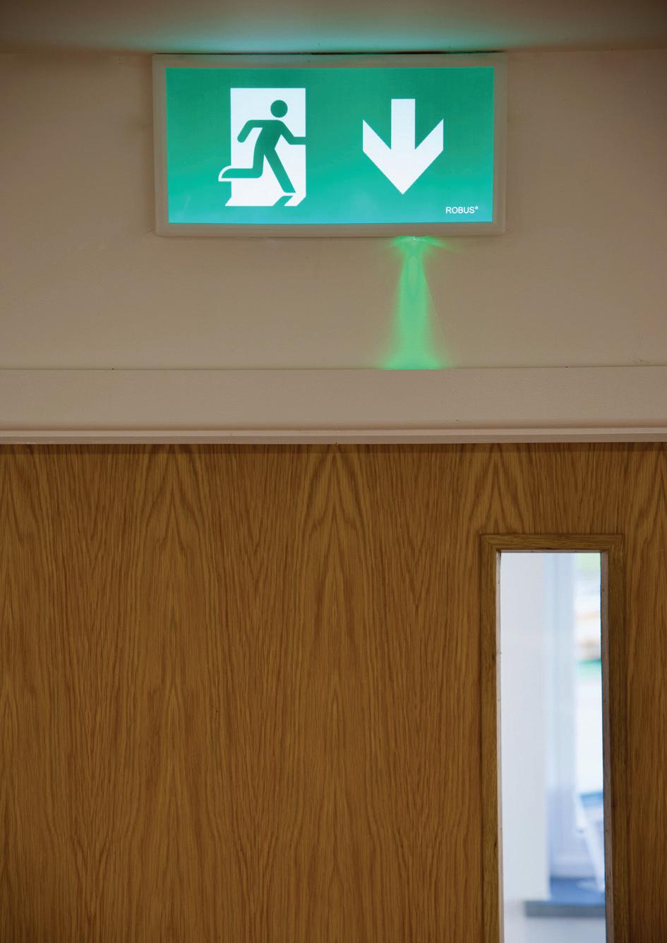
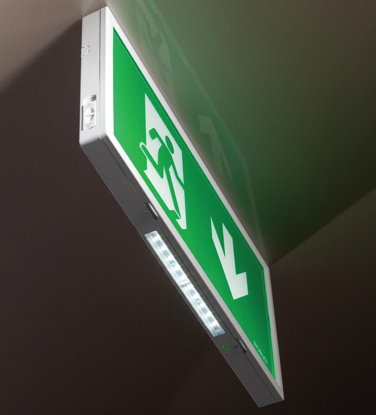
In this article the experts at ROBUS advise on how to best avoid a clash with your emergency signs.
Exit boxes are on the way out… and terrible lighting humour is still very much in!
Getting to grips with emergency lighting can challenge even the most experienced electrician, but being in the know will greatly reduce costs, save time and, most importantly, enhance safety.
A recent real-life scenario for a ROBUS Sales Manager involved a debate with a client’s fire safety consultant about exit signs. ROBUS installed a down arrow to lead people down a staircase, following the recommendations of its in-house lighting design team.
However, the consultant insisted on replacing it with a diagonal down arrow that was 12 times more expensive.
Why did this happen? In this case, the diagonal arrow was merely a suggestion in the regulations and not a requirement. This kind of mix-up happens quite often
given the depth and breadth of guidance and regulations.
That’s why in this article, we will dive into emergency signs to clear up some of the confusion.
How to get started
Emergency signs fall under the umbrella of emergency escape lighting. The Electrician's Guide to Emergency provides a procedure for identifying which areas require signage:
(a) carry out a risk assessment, to identify the hazards that will require emergency lighting, including high risk task areas; (b) refer to the evacuation strategy prepared for the fire detection and alarm system.
Top tip: Ensure the evacuation strategy is up-to-date and practical. For example, during a ROBUS project in a social housing building, the engineer discovered

that the evacuation route led residents to a closed courtyard, potentially trapping them. Outdated documents can also lead to dead ends, creating disasters during real emergencies.
After conducting your risk assessment, complete the following steps:
(c) position signs and luminaires at primary escape locations with direction signs if necessary, see Section 4.2;
(d) position luminaires to illuminate all points of emphasis and at additional locations;
(e) add luminaires as necessary to illuminate the escape routes;
(f) add luminaires as necessary to illuminate the open areas;
(g) illuminate high risk task areas, and (h) position safety signs (see Figure 4.1).
As you can see, signs appear high in this procedure. This is not only because clear directions are critical for guiding people safely along an evacuation route. In most cases, the emergency signs will be luminaires, and if not, they will require illumination.
Therefore, it makes sense to start with emergency signs to know how many additional luminaries you will require to meet the necessary lux levels for each area. By following these steps, you will minimise waste and avoid that all too common pitfall of installing more luminaires than required.
Where should emergency signs be installed?
Emergency signs should be installed where necessary to provide clear directions for building users. This includes:
● At exit doors
● Along escape routes
● At intersections in corridors
● Where there are stairs or escalators
● Where there are sudden changes in floor gradient, such as ramps
● In open areas (defined as rooms with a floor area greater than 60 m2) including large rooms and disability toilets
● On each floor of a building
● At safety equipment such as first aid locations, fire-fighting equipment, alarms, etc.
● At the nominated assembly area outside.
Viewing distances –height is important after all!
You’ll find viewing distances highlighted in the technical details of emergency signs. This is because the viewing distance for
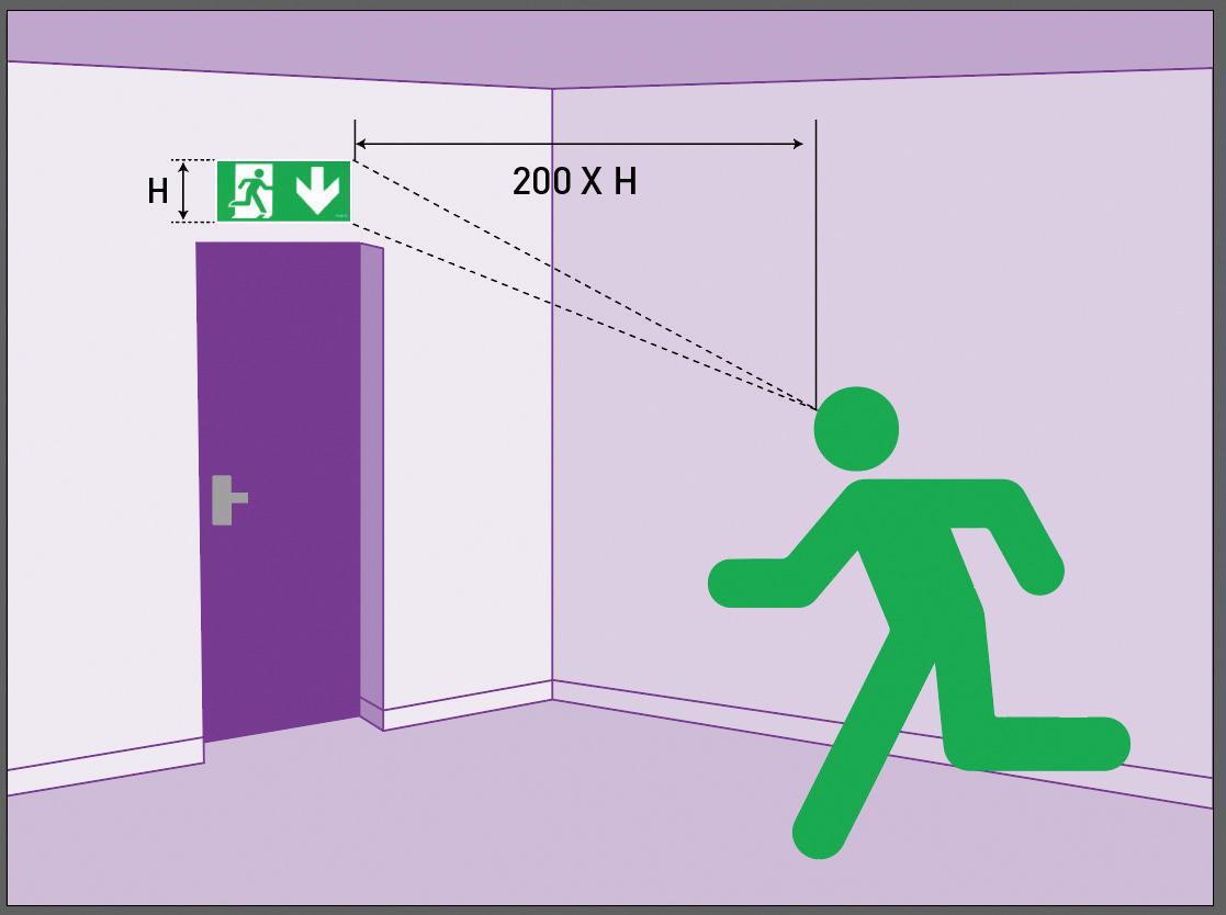
internally illuminated signs must be 200 x height of pictogram. If the sign isn't combined with a luminaire but rather lit from an external emergency fitting, then the distance is reduced to 100 x height of pictogram.
On the REX EXIT BOX ROBUS fitting, the internally illuminated sign is 265 high. Multiplying that by 200 gives us 33,000 mm, or 33 m. This is the maximum distance from which the sign can be seen and legibly understood. If the fitting is installed at the end of a long corridor, you may need to either use a larger pictogram or install an additional sign further along the corridor.
The viewing angle is important because reading a sign straight on is easier than from the side. To calculate the viewing distance from an angle, multiply the distance by the cosine of the angle.
Experienced manufacturers like ROBUS can provide designs that incorporate these requirements.
Which way should the arrow go?
The most confusing direction is for ‘straight on’ –should it be a down arrow or up arrow?
According to the Industry Committee on Emergency Lighting, ‘straight on’ should be indicated by an upwards arrow. However, if the sign leads to a door
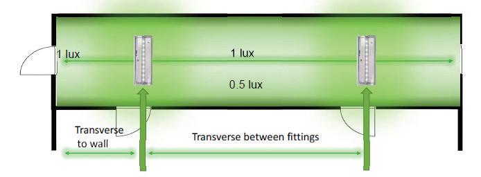
followed by a descending staircase or ramp, the arrow should point downwards. This isn't set in stone, so consider potential misunderstandings in your design. A common-sense approach and absolute consistency are essential in any emergency lighting design.
Buy smart, think about lumens
How many luminaires do you need? The answer will depend on the necessary lux levels as much as providing clear directions.
It makes sense to check the lumens for the products you’re purchasing. You may find that buying one high-lumen luminaire is more cost-effective than multiple cheaper, low-lumen luminaires.
For more information on emergency lighting regulations and guidance refer to BS 5266-1, the British Standard for emergency lighting, and the Electrician's Guide to Emergency

Whenever there is a request to replace an item of electrical equipment such as a distribution board we do need further information regarding the existing installation. If we were looking at a like-for-like replacement there wouldn’t be many areas for discussion or review.
But when we come across a situation as shown in the photographs, there are many inherent non-conformities which would have to be investigated and subject to remedial works before such a replacement could be carried out.
At first glance the distribution board looks fairly new but once the cover is opened, we can see missing blanks with exposed live parts where the copper bars are accessible.
With the cover removed, further issues are revealed: there are ‘floating contactors’ which have not been provided with a means of fixing and it isn’t clear if the control circuits are supplied from the same distribution board.
The openings at the top of the distribution board do not meet the requirements of IP4X where the metal trunking hasn’t been extended to the end of the distribution board, allowing access to
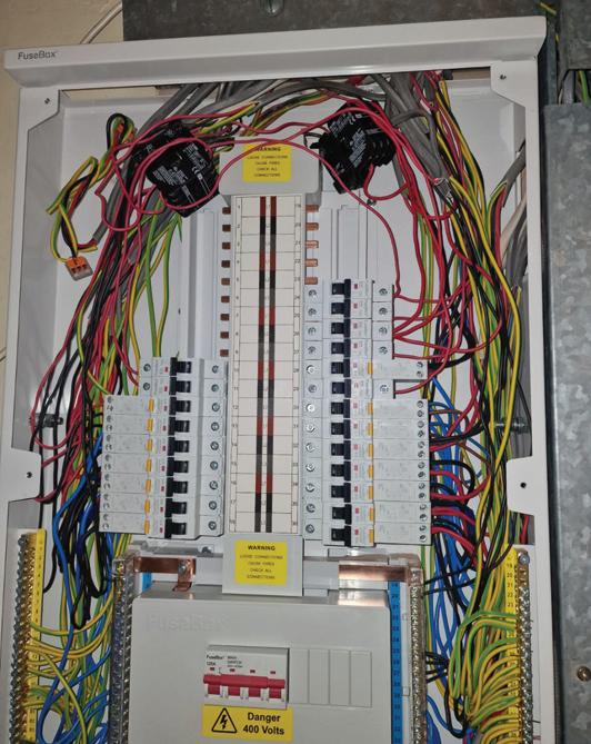
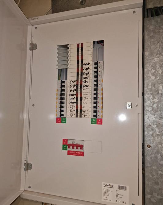
live parts and single insulated conductors. The metal trunking has similar issues where the containment doesn’t meet the IP4x.
Therefore, the classification code would be a C1, Danger present – immediate remedial action required, for exposed live terminals of accessible at the distribution board.


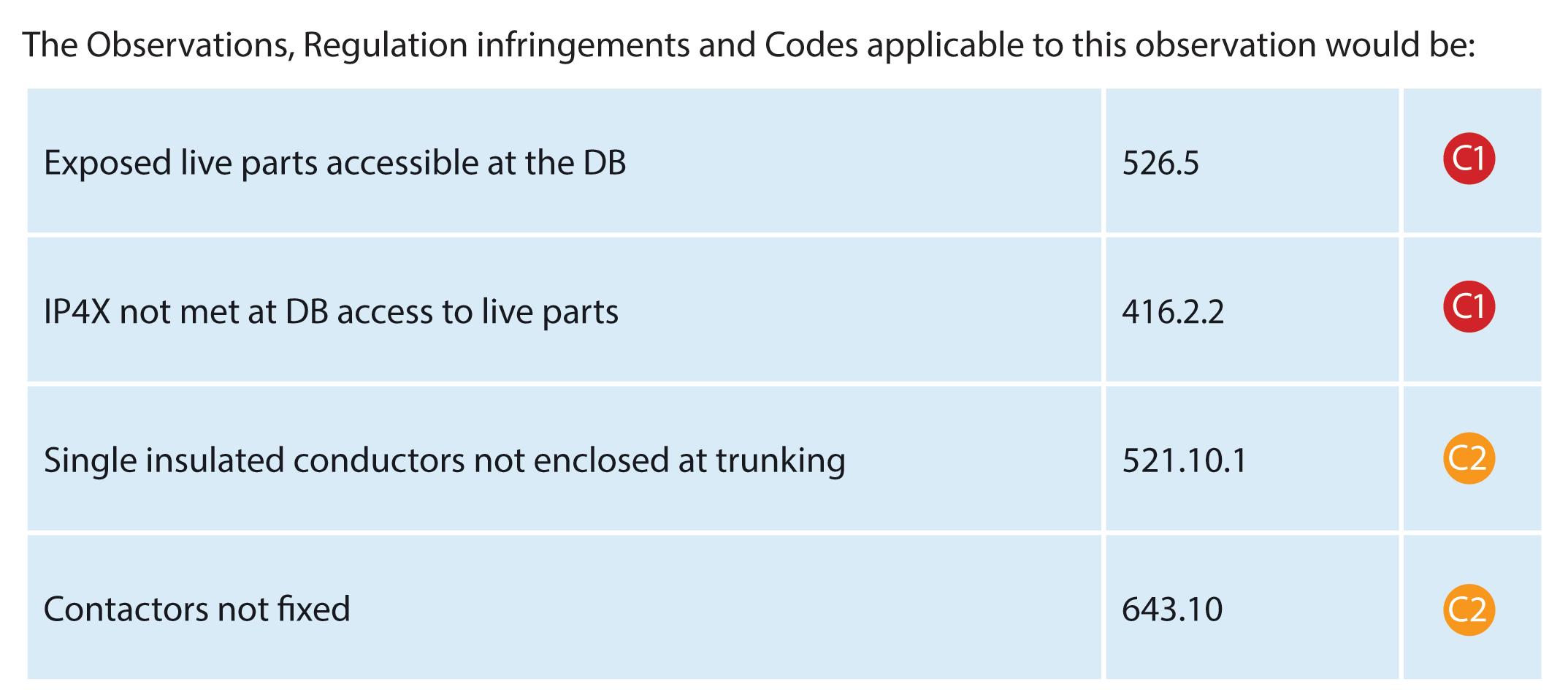
Updated for BS 7671:2018+A2:2022, NAPIT’s EICR Codebreakers publication is purpose-written to aid contractors, inspectors and clients, and now includes updates to align with Amendment 2 of the IET 18th Edition Wiring Regulations. The book is the perfect technical aid for electrical professionals and their customers.


Need help with cracking those all-important EICR codes? Every month the technical team at NAPIT will be studying your latest ‘Caught on Camera’ photos and offering advice on the next steps, should you find a similar installation. If you want the team at NAPIT to help crack your codes then send your pictures through to us at: pe@hamerville.co.uk


MARC SUGGITT: THE DIY’ER STRIKES! THIS IS JUST A SMALL SAMPLE FROM A RECENT JOB WE WERE WORKING ON. TRUST ME, IT GOT WORSE FROM THERE.
This is a common site when carrying out periodic inspection and testing on downlight installations. The lack of understanding of the requirements of BS 7671 to ensure the safety of the electrical installation for users, the property and any consequences with adjacent properties or residents is bordering on the criminal.
So, to the bones of the issues –the lack of connection between the circuit protective conductors removes the essential requirement for earth continuity throughout the length of each circuit. There’s also the removal of excessive length of the twin and earth cable sheath to expose the single insulated conductors.
Finally, the open pvc connector in the neutral conductor which has not been provided with an enclosure to contain the exposed live part contributes to a substandard installation for which any competent electrician would be appalled by.
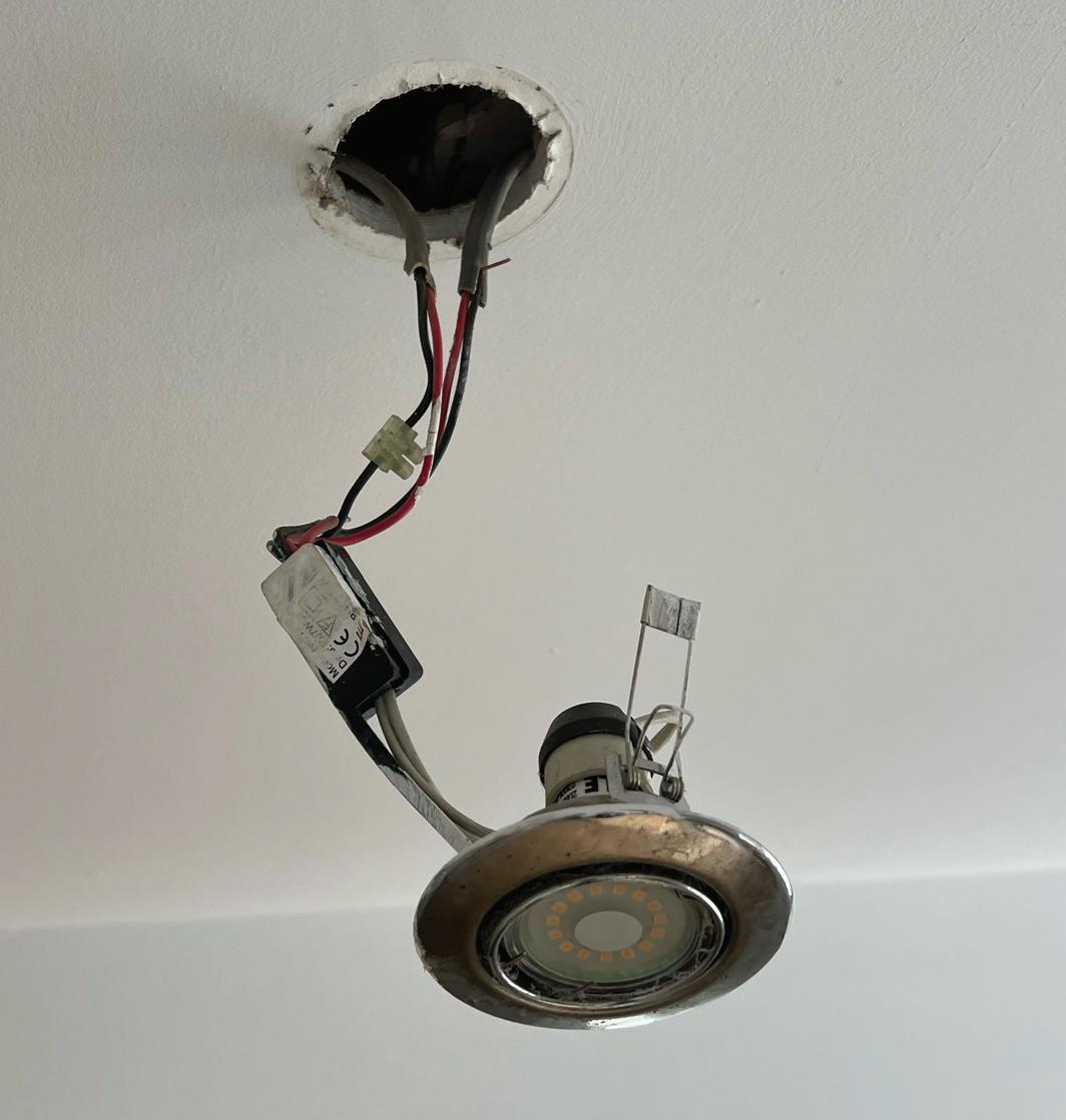

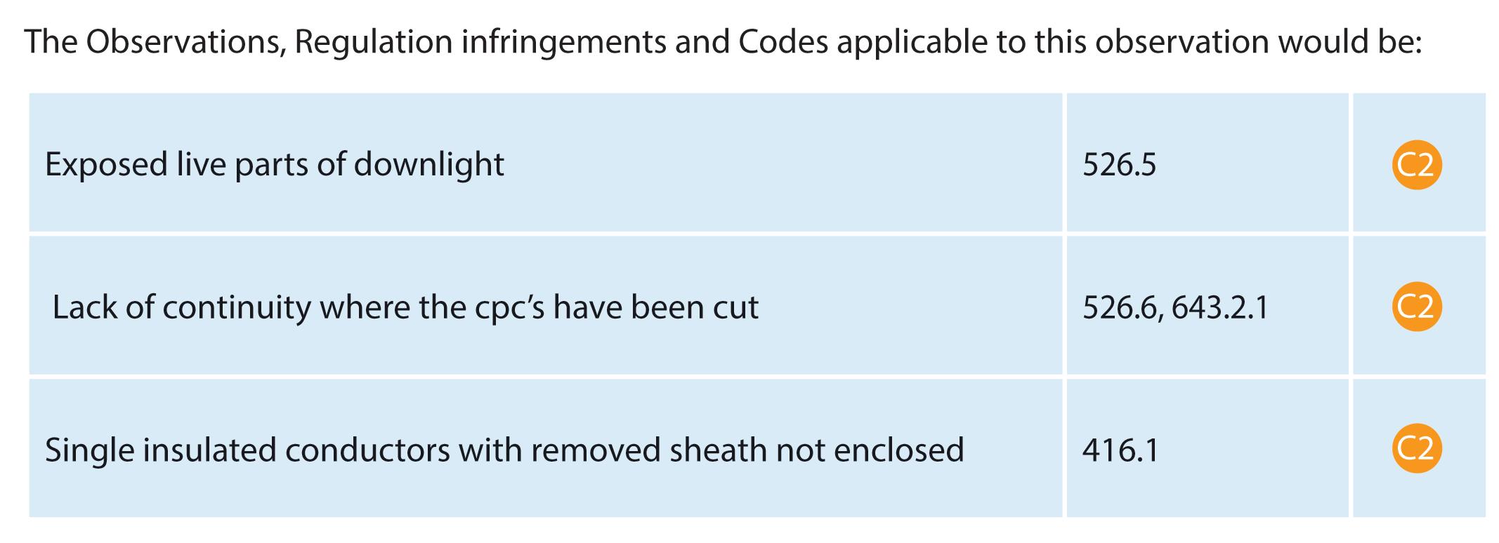
Therefore, the classification code would be a C2, Potentially dangerous – urgent remedial action required, for exposed live terminals of the connector above the downlight. ORDER
The A2:2022 18th Edition Codebreakers publication is priced at £22.00 (members) and £24.00 (non-members). It is available in both hard copy and digital versions * Price is VAT exempt and excludes postage and packaging.

As of September 2021, there has been a major overhaul to the energy ratings displayed on light bulbs, with the revision reflecting broader changes in the way energy efficiency is measured and regulated in the UK. The team at Enkin provides more detail.
The energy ratings displayed on bulbs are designed to help us understand how much energy that bulb uses, and how efficient it is in comparison to other options. These ratings are classified using lumens per watts; the higher the lumens, the higher the classification. This is displayed on the side of bulb packaging, with classifications from green to red, to easily identify which bulb is more energy efficient.
Fairly simple, right? Not quite. This classification has seen a drastic shift in recent years, and you might have noticed that the A++ energy rated bulb you usually purchase now has an energy rating of E. It can seem concerning, especially if you’re meticulous about saving energy in the home.
However, this isn’t a cause for concern. Bulbs have not suddenly become less efficient, the rating system has simply updated to reflect a new standard for industries to aim for when producing energy efficient bulbs.
Here’s how it works:
The most significant reason for the shift in energy ratings is the rapid development in lighting technology. Traditional incandescent bulbs, which were less efficient, have been largely replaced by LED lighting.
This newer technology consumes
significantly less energy and has a much longer lifespan, necessitating a re-evaluation of what constitutes an ‘efficient’ bulb.
However, the phase out of incandescent and halogen bulbs brought with it a new problem, as the vast majority of LED bulbs were being rated as A, A+ or A++, when compared to their highly inefficient predecessors.
With so many bulbs rated in the highest category for energy efficiency, there was no reason for manufacturers to develop more energy efficient technology.
Simply put, the new energy ratings incentivise producers to continue developing more energy efficient bulbs.
Globally, there has been a significant push to align industry standards when it comes to energy efficiency. Aligning the criteria used in different regions makes it easier for consumers to compare products.
In 2021 the EU took steps to achieve this by revising the energy labelling system, providing more accurate information in a much clearer way for the consumer.
The scale, which previously ranged from A+++ to G, was simplified to A to G, with no additional "+" categories. This change was made to account for the high efficiency of modern LEDs, ensuring the labels remain relevant and informative.
Environmental considerations
With the increasing emphasis on
reducing energy consumption to combat climate change and lower energy bills for consumers, the need for more stringent standards on energy ratings helps to drive the adoption of more efficient technologies.
This aids in reducing overall energy consumption, greenhouse gas emissions, and helps to save us all a few pennies on our energy bills.
What do these changes mean for you?
1. Easier comparisons
Revised energy ratings and clearer labelling with more accurate information makes it easier to compare the efficiency of different bulbs. The new system aims to paint a clearer picture of energy consumption, helping you to make a more informed decision when purchasing.
2. Incentivised efficiency
With manufacturers now being incentivised to create more energy efficient bulbs, older, less efficient bulbs will gradually be phased out, lending to a more energy efficient market for LED bulbs in general. Consumers are more likely to purchase a more efficient LED bulb, which proves to be more cost-effective over their lifespan, despite the higher upfront cost.
3. Environmental impact
Along with the long-term savings from using more sustainable LEDs, choosing
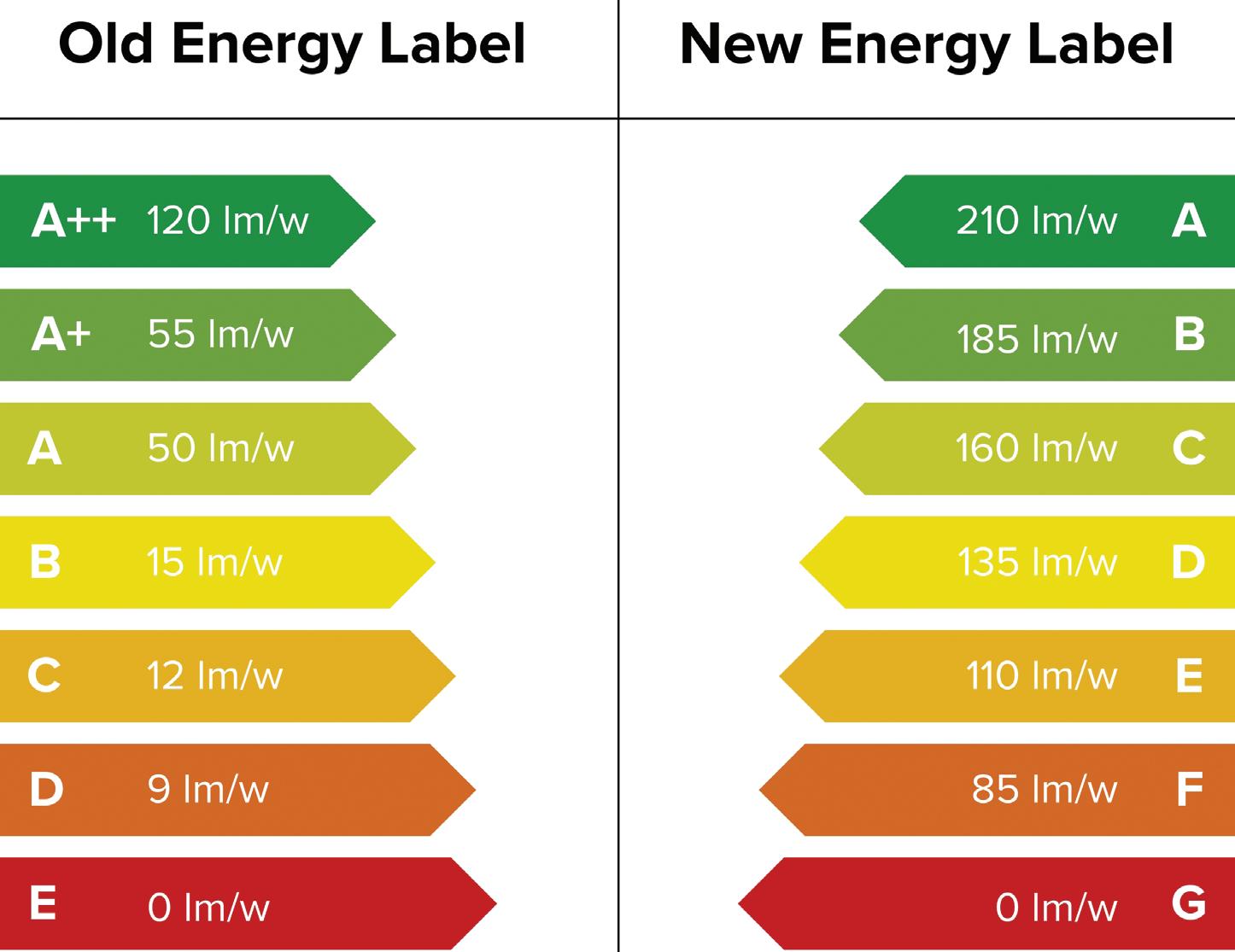
bulbs with a higher energy rating helps reduce your carbon footprint and contributes to broader environmental goals.
These recent changes in energy ratings on light bulbs reflect the ever-evolving landscape of lighting technology, as well as the global effort to promote energy efficiency and sustainability.
By being aware of these changes, and as technology continues to advance, we can make decisions that benefit both our wallets and the environment. We can expect to see more changes like this in future that will further fine-tune how we measure and communicate energy efficiency, so it’s crucial to stay informed.

The publication of Amendment 2 of BS 7671 (AMD2) introduced several changes to the requirements for insulation resistance testing within Part 6 of that standard. This article from the experts at NICEIC explains these changes and outlines the considerations for those carrying out such testing.
There is a fundamental requirement within Section 134 of BS 7671 that every electrical installation is subjected to appropriate inspection and testing:
● during construction; and
● on completion
before it is put into service to confirm compliance with the relevant requirements of that standard (134.2.1). This is supported by regulation 641.1 which calls for inspection and testing to be carried out both during the construction of the installation and on completion of the work. This requirement is particularly relevant to
“Any wiring can suffer damage to the insulation or conductors during the installation process or once it is installed, but prior to being energised.”
the insulation resistance testing of cables during construction.
The requirements for insulation resistance testing have been amended to clarify that all installed conductors must be subjected to testing at a voltage in excess of the voltage that
they will carry in normal service to confirm that they remain serviceable after being installed.
It is not sufficient to try and verify this by applying a DC test voltage which is more-or-less the same as the normal operating voltage. The use of a higher-than-normal operating voltage test is more likely to detect conductor or insulation damage.
Why do we carry out insulation resistance tests on cables?
Any wiring can suffer damage to the insulation or conductors during the installation process or once it is installed, but prior to being energised. Unfortunately, it is often overlooked that regulation 641.1 calls for inspection and
“Effective insulation of conductors is necessary to provide basic protection and to prevent short-circuits and earth faults.”
testing to be carried out, not only on completion, but also during construction.
Testing at relevant times during the construction phase helps to ensure that any damage that may have occurred is identified and rectified at an early stage of the project, rather than after completion, which would make any necessary remedial work much more intrusive and costly.
Effective insulation of conductors is necessary to provide basic protection and to prevent short-circuits and earth faults. Unintended leakage currents due to inadequate insulation can present a risk of electric shock to persons and livestock. This can also lead to further deterioration to the insulation and conductors if allowed to persist, which may present a fire risk.
It is important therefore that a test conducted at a voltage in excess of the voltage at which the circuit will subsequently operate, is carried out using a suitable test instrument according to BS EN 61557-2, to highlight any such damage.
What are the testing requirements in BS 7671?
Regulation 643.3.1 requires that the insulation resistance of installed circuits is measured:
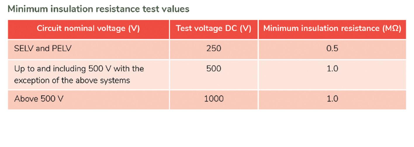
● between live conductors; and
● between live conductors and the protective conductor connected to the earthing arrangement, with the line and neutral conductors connected together, where appropriate.
This measurement shall take place at the appropriate DC test voltage given in Table 64 of BS 7671 , reproduced as Table 1 , according to the circuit’s nominal voltage at least once after the installation of the cables.
Regulation 643.3.3 has been modified and now states that:
● Where connected equipment is likely to influence the measurement or the result obtained from testing, or be damaged, the test at the appropriate DC test voltage given in Table 64, shall be applied prior to the connection of such equipment; and
● After connection of the equipment, a test at 250 V DC shall be applied between live conductors and the protective conductor connected to the earthing arrangement. The measured insulation resistance obtained from this test shall have a value of at least 1 MΩ.
Such testing carried out after the connection of the equipment is primarily to confirm the effectiveness of those connections.
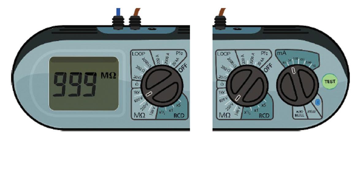
A new note to this requirement states that some manufacturer’s instructions may still advise that certain equipment must be disconnected prior
to carrying out the 250 V DC test to avoid its influencing any test results obtained.
Anyone carrying out inspection and testing of electrical installations designed and installed in accordance with the requirements of BS 7671:2018+A2:2022 (AMD2) must familiarise themselves with the changes made to the requirements for insulation resistance testing.
In the case of initial verification, all conductors shall be tested at least once after installation at the test voltage indicated in Table 64 of BS 7671, appropriate to the circuit’s nominal voltage. This should preferably be done prior to the connection of any equipment that is likely to influence the measurement or result of the test, or to be damaged by the test voltage.
This test is to verify that the conductors remain in a serviceable condition post-installation.
Subsequently, once equipment is connected, a test at 250 V DC shall be performed between the live conductors and the protective conductor connected to the earthing arrangement. This test verifies the connections made since the 500 V DC test was performed.
Although not stated in BS 7671, when carrying out testing during a periodic inspection, it would be logical to perform insulation resistance testing at 250 V DC initially due to the presence of items of connected equipment that may either be damaged by a higher applied test voltage or might influence the results obtained during testing.
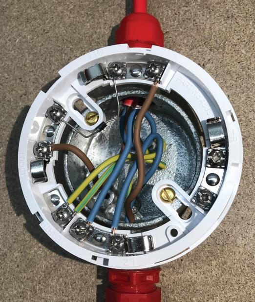
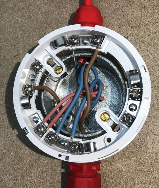
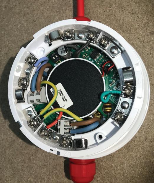
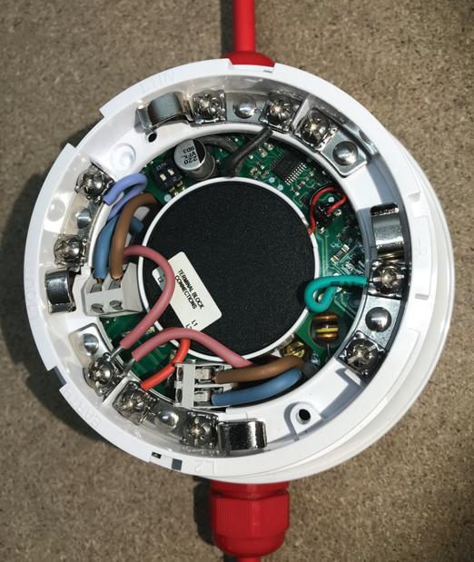
Following the latest fire industry regulatory updates, the team at Illumino Ignis explain more about why pink sleeving must now be used for functional earths.
Understanding the distinctions between functional earth and protective conductors is vital for fire detection and fire alarm system safety and functionality. The latest technical bulletin from the Fire Industry Association (FIA) shares the critical roles these conductors play, detailing the unique colour coding standards designed to prevent misidentification.
What are the changes?
The standard BS 7671:2018+A2 mandates that functional earth must be identifiable to avoid confusion with other earthing systems. Specifically, it specifies that functional earth conductors should be marked with pink sleeving (as per clause 514.4 & Table 51). This requirement now extends explicitly to fire alarm installations.
This recent amendment ensures that functional earths are easily distinguishable from other conductors. This prevents misconnection –such as inadvertently routing a protective earth through a functional earth cable –and guarantees the correct operation of the equipment they serve.
Previously, BS 7671 required that low-voltage cables be identifiable with pink sleeving. However, fire alarm installations were not specifically addressed, leading engineers to use
green and yellow cables.
Now, fire alarm installations are classified within low-voltage systems, clarifying the standard and preventing misunderstandings.
These additions have been made to protect electricians and fire alarm engineers from electrical safety hazards. When both protective and functional earths are sleeved in green and yellow, there is a significant risk of confusion.
These updates ensure that different types of earthing are easily and correctly identified, minimising the risk of installation and maintenance errors that could lead to equipment malfunctions.
The protective earth's primary role is to provide a safe path for fault currents to be directed to earth, allowing a large fault current to flow through the line conductor. This rapid fault current flow triggers the protective device to operate quickly, typically within 0.4 seconds.
If functional earth is included in this path, high fault currents may pass through fire detection and alarm equipment, potentially causing EMC spikes that damage sensitive electronics.
Therefore, a well-designed earthing system that keeps functional and protective earths separate is essential to
ensure safety and functionality in electrical installations.
The pink-coloured sleeving should be applied to the conductor's insulation, making it visibly distinct from other wires within the electrical installation.
This is particularly important in complex systems where multiple types of earthing are present, as it helps technicians and engineers quickly identify and correctly handle the functional earth conductors.
This is especially relevant in fire detection and fire alarm systems, where extra-low voltage (ELV) circuits also require functional earths to be identified with pink sleeving to ensure clarity and proper function of these critical safety systems.
This technical bulletin from the FIA Has been released to provide fire alarm engineers with the correct knowledge about which cables should be used, ensuring the integrity and safety of your fire safety systems.
By following these guidelines, outlined in BS 7671 and BS 5839-1, you can ensure the integrity and safety of your fire safety system installations.


Steve Humphreys, Technical Commercial Manager at NAPIT, explores fire performance cables in detail.
Acable’s fire performance is a key area for designers of electrical installations to consider. Although electrical designers are generally not fire safety experts, they should ensure that the installation complies with applicable building regulations, standards and guidance.
This may result in the designer selecting fire performance cables and wiring systems based on the physical building, its layout and intended use.
The client’s requirements and the specification produced by the architect may also require cables to be selected with fire safety in mind.
Cables with very limited fire performance may in fact contribute to a fire or be the reason a fire spreads more quickly and produces toxic fumes or smoke. Any circuits that are intended for emergency warning or escape, such as fire detection and emergency lighting, should be designed to ensure that the system functions as intended.
Amendment 2 of BS 7671:2018 highlighted the importance of fire safety design of electrical installations within
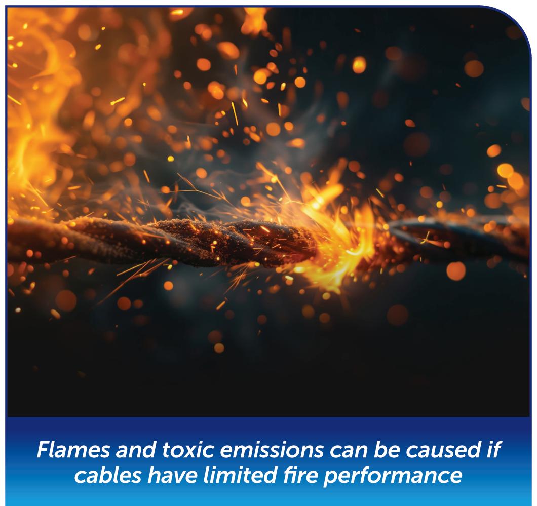
buildings. The fire safety of a building should now be documented, including details of the electrical system and the selection of cables with improved fire performance.
Types of fire performance cables
Thankfully, there is now a much wider
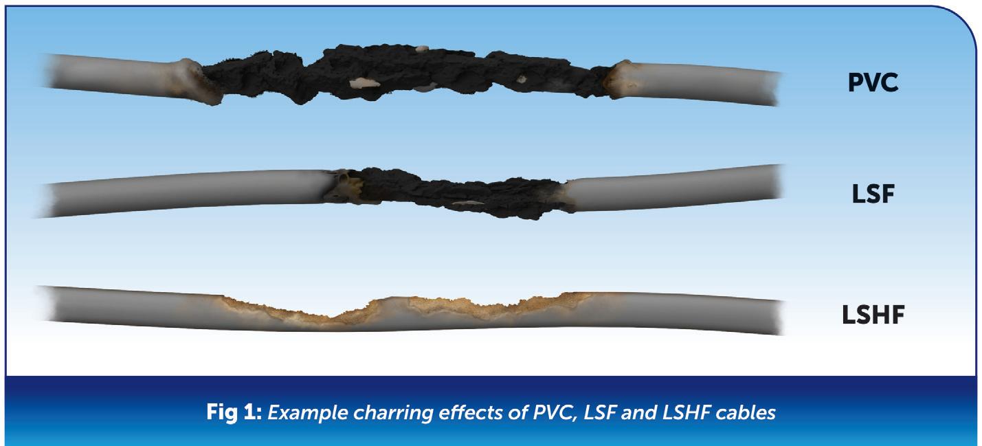
choice for designers and installers when it comes to selecting an appropriate fire performance cable. As mentioned earlier, this will depend on its use and application.
Fire performance cables generally fall into the following three categories:
● Low smoke emission cables
● Flame retardant cables
● Fire resistant cables
Low smoke emission cables
High-density opaque smoke can seriously impact visibility during a fire, and this could have very serious consequences for evacuation and firefighting procedures. There is also an added risk of toxic fumes within the smoke causing occupants to choke, possibly leading to a fatality.
Low smoke emission cables are designed to emit minimal smoke and, in
some cases, no halogen when exposed to fire. These cables are typically made with materials that contain low levels of halogens, such as fluorine, chlorine, bromine and iodine. These materials produce less smoke and toxic gas when burned compared to traditional cables, which often contain PVC (polyvinyl chloride) insulation and sheathing.
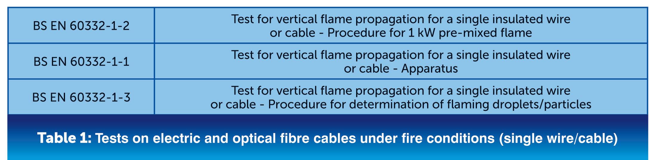
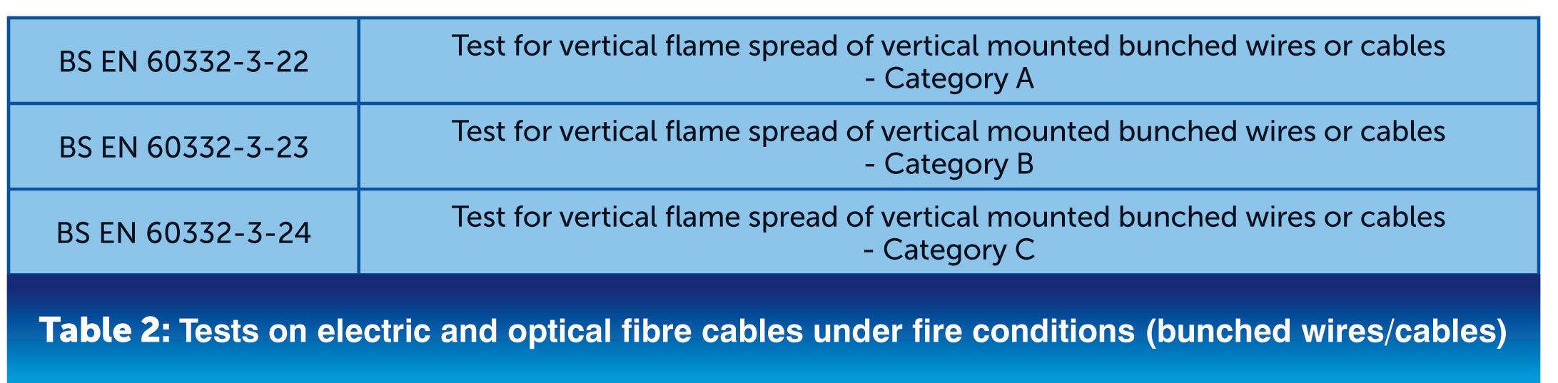
Where low smoke emission cables are used, they must be tested in accordance with BS EN 61034-2. A smoke density test assesses the level of light transmitted from one side of a chamber to the other with the cable under fire conditions. A minimum standard light transmittance level of 60% is required.
Most standard PVC cables, whether singles, sheathed or insulated, will have a low smoke emission variety. These are sometimes referred to as Low Smoke Halogen Free (LSHF) or Low Smoke and Fume (LSF) cables.
Designers still need to be careful, as there are key differences between LSHF and LSF cables. Some examples of how PVC, LSF and LSHF cables char when burnt are shown in Fig 1
LSHF cables have no PVC or halogen compounds. These cables do smoke when burnt but will produce less than 0.5% hydrogen chloride gas.
During a fire, the cable will produce a small amount of light grey smoke, however, this has greater visibility than the thick black smoke produced by other PVC cables.
LSF cables are made up of a modified
PVC compound. This compound produces less hydrogen chloride gas, around 20%, than standard PVC cables.
During a fire, the cable will produce thick black smoke due to the presence of PVC and halogen. This cable can sometimes be selected by mistake as it is assumed that it has the same fire performance properties as LSHF.
Flame retardant cables
Flame retardant cables are designed to be resistant to catching fire and restrict the spread of a fire by reducing the rate of combustion. They are constructed using materials that have inherent flame-retardant properties or by applying flame-retardant coatings or additives to the cable insulation.
These materials may include halogen-free compounds, fluoropolymers, or silicone rubber. In addition to producing very little smoke, these cables have self- extinguishing properties once the flame is removed. This prevents the fire from spreading
further along the cable length.
Flame retardant cables are required to meet specific safety standards and regulations depending on the application and location. Standard testing relating to flame retardant cables is divided into a number of categories, such as single and bunch wired. These are highlighted in Table 1 and Table 2.
BS EN 60332-3-22 (Category A) is the highest level of flame-retardant cable standard testing.
It is worth pointing out that the primary goal of a flame-retardant cable is to minimise the spread of fire. During a fire, it might also maintain the integrity of the circuit, but only for a certain amount of time.
However, this type of cable should not be used if the circuit is required to maintain circuit integrity and continue to work for a specific time under fire conditions.
Fire resistant cables are designed to maintain circuit integrity and continue to work for a specific time under fire conditions. Fire resistant cables are constructed using materials that can withstand high temperatures.
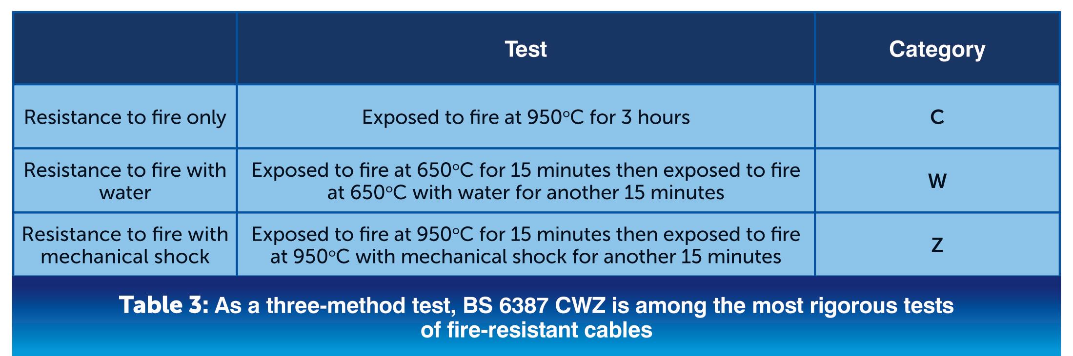
Common materials include mica tape, which acts as a fire barrier around the conductor, and
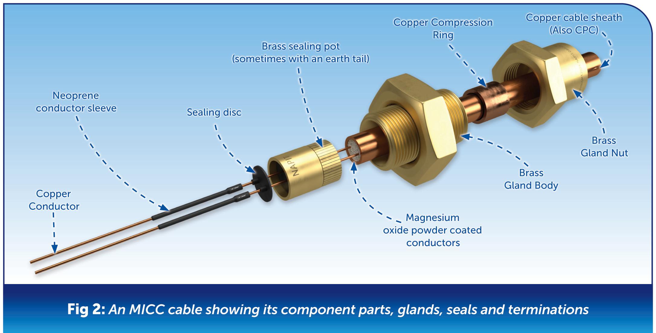
insulation made from silicone, glass, or thermoset compounds. These types of cables will also have low smoke, no halogen and non-toxic properties.
These cables can endure extreme temperatures, often up to 750°C or more for short periods of time, without losing their electrical integrity. This makes this type of cable ideal for applications such as:
● Fire alarms and safety systems
● Emergency lighting
● Critical power supplies
Fire resistant cables must adhere to specific standards, such as the IEC 60331, BS 6387 and others, which define the testing methods for fire resistance alone, fire resistance with water and fire resistance with mechanical shock. These tests ensure that the cables can perform under real fire conditions.
BS 6387 CWZ is one of the most stringent tests of fire resistant cables as it consists of three test methods, such as those highlighted in Table 3
Mineral insulated copper cable (MICC) is a good example of a fire-resistant cable. This type uses a copper conductor, a magnesium oxide insulator,
and a copper sheath. It is highly fire-resistant and can withstand temperatures up to 1,000°C. Because the magnesium oxide is hydroscopic (will absorb moisture from the atmosphere) specialist glands and seals are used to terminate the cable, as shown in Fig 2
When selecting cables for an electrical installation the designer needs to consider if fire performance cables are required for all or part of the installation. In light of fairly recent tragedies, such as the Grenfell Tower fire, it is more important than ever to select cables that meet fire safety standards and requirements.
There are now plenty of choices and types of fire performance cables to suit most applications and installations. BS 7671 clearly states that designers should work with other interested parties to ensure the fire safety of electrical installations is a prime consideration. Integrating fire performance cables into buildings provides enhanced resilience, reduces the impact of fire incidents and, most importantly, safeguards lives.


This article from the experts at NICEIC looks at electrical installations in medical locations, and will consider the scope of Section 710 of BS 7671 including some of the design requirements. Consideration will also be given to the use of system Grouping and how the classification of a safety service supply given in Section 560 is applied to such medical locations.
The intention of Section 710 is to provide enhanced reliability for the electrical installation, and greater electrical safety within the medical environment for both patients and medical staff.
The risk to a patient is greatly increased in a medical location due to:
● the threat from failure of the supply to medical equipment, especially that used for life support; and
● the natural reduction in body resistance inherent with open wounds, intrusive procedures and subsequent decline in patient defensive capacity either from induced medication or while anaesthetised.
As with all the special locations in Part 7, the requirements for Section 710 supplement or modify the general requirements of BS 7671 and are intended for those parts of the electrical
installation in locations providing patient care, diagnosis, treatment, and monitoring. The requirements do not apply to items of medical electrical equipment.
The scope of Section 710 outlines particular requirements applicable to patient healthcare centres and facilities including:
● hospitals;
● private clinics;
● medical and dental practices;
● dedicated medical rooms in the workplace; and
● patient medical research establishments.
The requirements may also be applied to veterinary clinics, where applicable.
Healthcare-related construction contracts must also meet the requirements specified in the supporting information for healthcare premises outlined in the Health Technical
Memorandum (HTM) 06-01 Electrical services supply and distribution, and 06-02 Electrical safety guidance for low voltage systems, published by the Department of Health.
Equivalent guidance documents are available for the devolved administrations: Scotland (SHTM), Wales (WHTM) and Northern Ireland (HTM) (Note 6 to regulation 710.1 refers).
Although, there are often subtle differences in the approach between BS 7671 and the specific HTM, the designer should always comply with the requirements of BS 7671
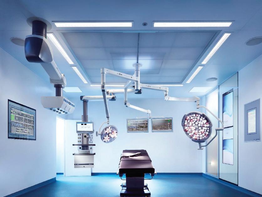
Where the standard does not provide sufficient information on a particular matter or detail, guidance in the relevant HTM should then be applied. However, such guidance should not contradict the requirements of BS 7671
Part 3 of BS 7671 outlines the characteristics that need to be assessed for all electrical installations.
The designer having responsibility of the electrical installation, within a medical location, is required to determine both the appropriate Group into which a particular medical location falls, and the classification that is to be applied to the electrical safety services in those locations.
The classification of a medical location is typically based on the:
● type of physical contact between the patient and the applied parts1 of medical equipment (ME) or ME systems;
● threat to patient safety in the event of a loss of supply; and
● purpose for which the location is to be used.
To identify the appropriate level of classification that should be applied,
based on the intended medical procedures likely to take place within the location, it is essential for the electrical installation designer to liaise with medical/clinical specialists (710.3).
To ensure safety in a medical location, where the location is to be used for multiple procedures or medical treatments, the requirements applicable to the most onerous usage should be applied.
The guidance given in Table 1 highlights the definitions for Groups 0, 1 and 2 locations identified in Part 2 of BS 7671 and provides, based on Annex A710 of Section 710, some examples of rooms likely to be included in each Group.
It remains the responsibility of the designer in consultation with the relevant clinical staff to determine the appropriate Group for a particular location. It should also be borne in mind that the listing is not definitive.
As described previously, the failure of an electrical supply in a medical location could cause danger to life. Appropriate safety services are therefore necessary to prevent such risk, and may typically include the provision for a standby supply for an operating theatre light.
Regulation 560.4.1 provides the classification of supplies for safety services. Section 710 requires such types of automatic supplies for safety services to be operational within a maximum changeover time designated for a particular area.
Table A710 of the annex to Section 710 provides guidance on the maximum permissible changeover times in typical medical locations.
For example, within bedrooms and massage rooms a changeover time
greater than 0.5 s and not exceeding 15 s is recommended while a time not exceeding 0.5 s is recommended for supplies to luminaires and life-support equipment in locations such as operating theatres.
The requirements for other sections in Part 7 of BS 7671 may also need to be considered, particularly where it is necessary to modify the electrical installation due to a change of utilization for the location. For example, where such intended work includes areas containing a bath or shower (701), or for mobile medical or transportable units (717).
Care should be taken to ensure that any such installations, or necessary work, do not influence or compromise the level of safety imposed by Section 710, including the effects from:
● fault current;
● electromagnetic interference EMI;
● electromagnetic compatibility EMC; or
● fire.
Although BS 7671 should not be applied retrospectively, when considering electrical work in an existing medical location, every intended alteration or addition should be preceded with a full analysis of risk to ensure that the intended work is appropriate and not liable to compromise the level of safety.
Summary
This article has outlined some of the considerations given in the scope of Section 710 of BS 7671 for various types of medical facilities. The requirements for specific Groups and safety service supply classifications utilised within a medical/healthcare environment have also been considered.
We would like to acknowledge and thank Brandon Medical for providing the image used within this article. GET MORE DETAILS ABOUT NICEIC REGISTRATION AT: WWW.RDR.LINK/EBH021
IN THIS REGULAR COLUMN, DR. TOM BROOKES, MD AT ZZEUS TRAINING AND CHAIRMAN OF THE FSA, ANSWERS YOUR QUESTIONS RELATED TO FIRE SAFETY. IN THIS EDITION HE LOOKS AT THE CORRECT CLIPPING DISTANCES FOR FIRE-RESISTANT CABLES.
What are the correct clipping distances for fire-resisting cables?
My manager has instructed us to clip at 1 metre intervals, however I’m concerned that this may compromise circuit integrity during a fire. Could you clarify the correct distances and the potential consequences of incorrect spacing?
When determining appropriate clipping distances for fire-resistant cables, BS 5839-1:2017 provides essential guidance for installing and supporting alarm cables, particularly in sections 26.2(f) and 26.2(g), and Clause 37, which addresses installation practices and workmanship.
A critical aspect of the standard is the emphasis on ensuring the circuit integrity of cables during a fire, which is vital for the safety of both building occupants and emergency services.
To prevent premature failure, the standard explicitly prohibits using plastic clips and ties as the primary means of support, which could melt in high temperatures. Instead, it advises following the recommendations provided by cable manufacturers for secure fixings.
The tragic events of the Harrow Court fire in Stevenage on 2nd February 2005 serves as a stark reminder of the consequences of incorrect cable fixings.
Falling cables, supported by non-fire-resistant fixings, played a significant role in the deaths of two firefighters. This tragedy underscores the critical need for fire-resistant cable supports, ensuring cables remain securely fixed during a fire.
Subclause 37.2(b) of BS 5839-1:2017 mandates that fixings must be secure and in accordance with the manufacturer’s guidelines. It also specifies that suspended ceilings shouldn’t be relied upon for supporting cables, as they can fail in fire conditions.
Cable manufacturers generally recommend fixing intervals of 300 mm for horizontal runs and 400 mm for vertical installations, especially for cables with diameters between 8 mm and 15 mm. These intervals are important for maintaining circuit integrity, as demonstrated by testing under BS 8434-2, which validates similar fixing arrangements for fire-resisting cables.
In certain circumstances, such as vertical cable drops in areas that are less accessible, slightly extended fixing intervals may be considered acceptable after thorough risk assessments by system designers and installers.
An example of this is the vertical drop of cables from a roof or floor to a device within a suspended ceiling. In these cases, the cable industry allows some flexibility, permitting vertical cable drops without fixing to structural elements, as long as the following conditions are met:
1. The maximum allowable vertical cable drop without fixing is 1 metre.
2. Fixings should be placed as close as practicably possible to the vertical drop to restrict cable movement and prevent slack.
3. Any spare cable loops intended for future re-termination must be securely fixed to avoid kinking.
4. The manufacturer’s minimum bending radius must be followed, particularly in cable loops, at device entry points, or where the cable changes direction beyond the last fixing.
5. Loop diameters should generally not exceed 150 mm, unless the manufacturer's recommendations specify otherwise.
6. Surplus horizontal cable should be kept to an absolute minimum.
Finally, BS 7671 contains a general requirement that wiring systems must be supported in a way that prevents premature collapse in the event of a fire. This provision further reinforces the prohibition on the use of plastic clips and ties for fire-resistant cables.
For more guidance on BS 7671, the IET On-Site Guide is a valuable resource, offering detailed advice on compliance and best practices for electrical installations, ensuring safety and reliability during fire events.
DO YOU HAVE A QUESTION YOU'D LIKE ANSWERED? EMAIL YOUR QUERIES TO: TOM@ZZEUS.ORG.UK
GET MORE DETAILS ABOUT ZZEUS TRAINING AND THE RANGE OF COURSES ON OFFER AT: WWW.RDR.LINK/EBH022


This type of installation work is down to a lack of understanding where the installer may not normally work with pvc/pvc cable and the need for green and yellow oversleeving for the bare copper circuit protective conductors. At least there was some knowledge, although misguided, for the need of the bare conductor to be provided with oversleeving.
The use of both red and black sleeving or, to correctly term it, stripped insulation, from the live conductors, creates even further confusion.
Within the electrical industry we are all aware that any protective conductor, with the exception of a functional earthing conductor, shall be a bi-colour combination of green-and-yellow.
Table 51 of BS 7671 provides the ‘Alphanumeric’ designation and the colour for identification of conductors which will remove any confusion with the function of all conductors within an electrical installation.
This lack of compliance with the requirements of BS 7671 can result in incorrect connections, unsafe installations and further investigation to determine and carry out rectification works to meet the correct identification of the conductors within the installation.
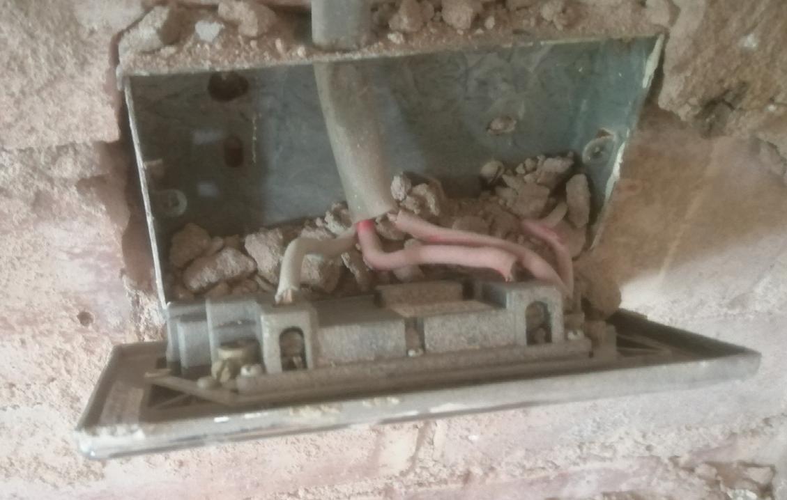

Therefore, the classification code would be a C2, Potentially dangerous – urgent remedial action required, for incorrect identification of conductors at socket-outlets and other points within the installation.
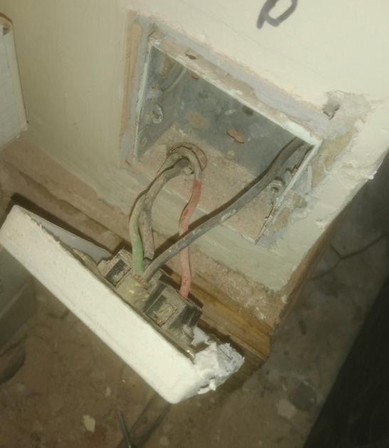
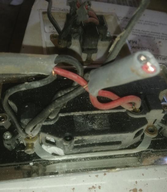
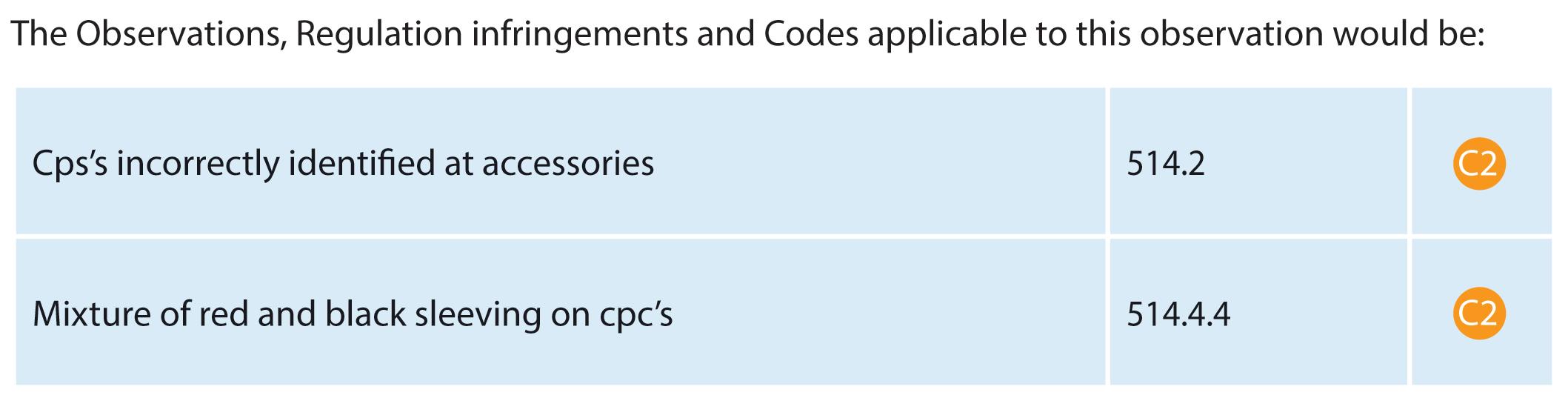
Updated for BS 7671:2018+A2:2022, NAPIT’s EICR Codebreakers publication is purpose-written to aid contractors, inspectors and clients, and now includes updates to align with Amendment 2 of the IET 18th Edition Wiring Regulations. The book is the perfect technical aid for electrical professionals and their customers.


Need help with cracking those all-important EICR codes? Every month the technical team at NAPIT will be studying your latest ‘Caught on Camera’ photos and offering advice on the next steps, should you find a similar installation. If you want the team at NAPIT to help crack your codes then send your pictures through to us at: pe@hamerville.co.uk


DARREN OVEREND: WE WERE CALLED OUT TO AN OUTDOOR LIGHTING JOINT BOX WHICH HAD BEEN REPORTED AS 'GETTING HOT’. THIS PICTURE MIGHT EXPLAIN
When designing an electrical installation any external influences that can affect installed equipment must be taken into account and the appropriate measures employed to prevent safety issues or damage occurring throughout the expected lifespan.
Although steel conduit boxes can be utilised for external installation, further steps would have needed to be taken to prevent ingress of moisture, water or condensation. The normal neoprene gaskets for fitting under the box lid, while providing some protection, would not eliminate water ingress or condensation.
The conduit box in the image displays a few issues, where the box has been installed vertically and has not been fitted with a suitable IP rated cable gland at the top. The evidence of silicon around the gland and within the box is evidence of the incompatibility for the location installed.
The evidence of water ingress, the build-up of corrosion and the apparent tracking between live conductors or to the earthed metalwork without the operation of the lighting circuit overcurrent protective device would lead to the creation of a mini water heater. If the circuit protective conductor has not been terminated, which is difficult to verify from a photograph, it could also be a contributory factor in the conduit box overheating.
Therefore, the classification code would be a C2, Potentially dangerous –urgent remedial action required, for lack of consideration for external influences, tracking fault between conductors and apparent lack of continuity of the circuit protective conductor.
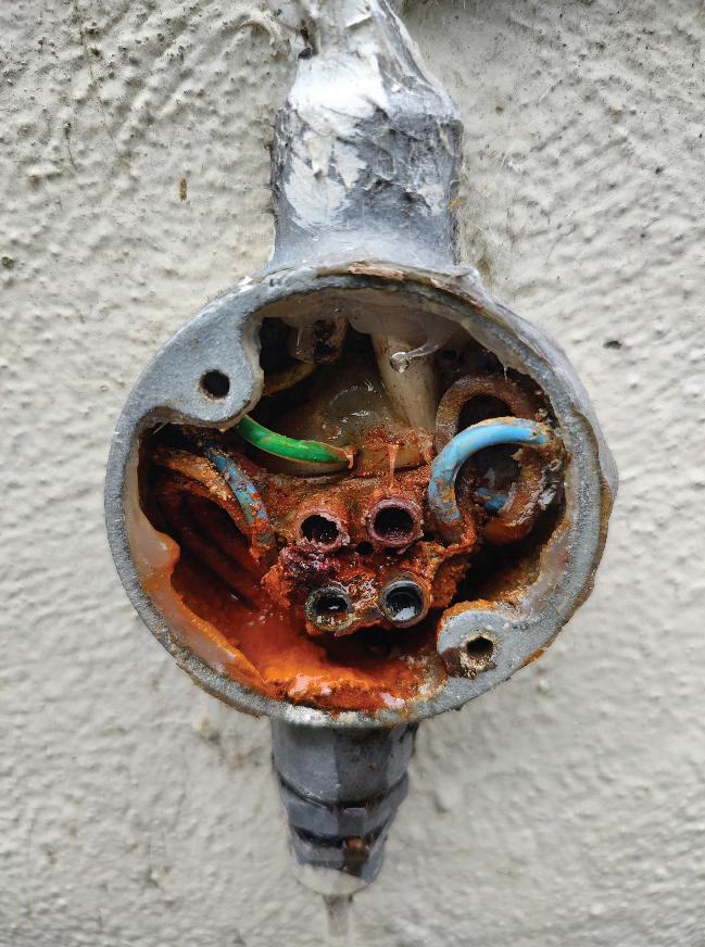

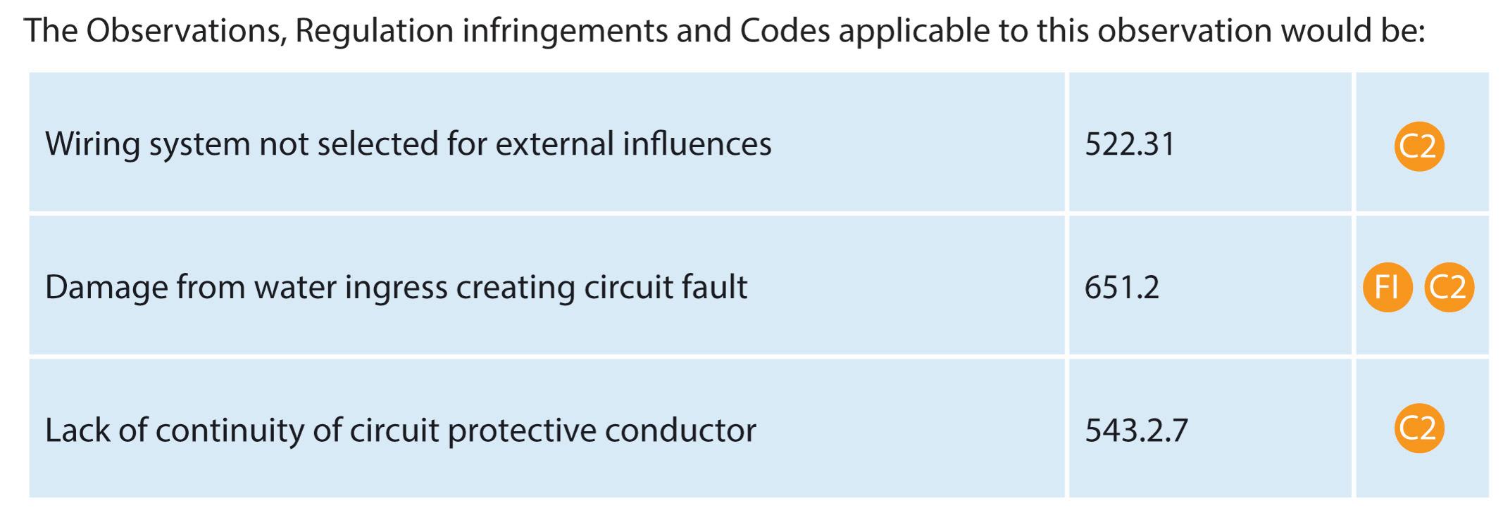
The A2:2022 18th Edition Codebreakers publication is priced at £22.00 (members) and £24.00 (non-members). It is available in both hard copy and digital versions * Price is VAT exempt and excludes postage and packaging.
Hager's Technical Training Manager, Paul Chaffers, discusses RCD Types and applications for electric vehicle charging installations whilst considering the requirements of BS 7671:2018+A3:2024.
RCD terminology
RCD has become a generic term used for many devices that protect against earth faults. With most devices available with different operating characteristics, it is essential that the correct choice is made.
For certain applications, the type and sensitivity may be prescribed, usually by BS 7671:2018+A3:2024 or may be provided as part of a design specification.
RCCB (Residual current operated circuit-breaker without Integral overcurrent protection)
RCCBs are frequently used in split-load consumer units, see Fig 1. They’re designed to make, carry, and break currents by means of mechanical switching and operate when the residual current reaches its set value.
As there’s no integral overcurrent protection provided, a suitably rated overcurrent protective device (OCPD) must be used for the associated final circuit(s). RCCBs are available for singlephase or three-phase applications (2 or 4-pole), usually with 30 mA, 100 mA or 300 mA sensitivity settings, with time delay options for 100 mA and 300 mA RCCBs.
RCCB overload protection
As well as providing overcurrent protection to any final circuits, Regulation 536.4.3.2 requires overload protection to be provided to those devices within a consumer unit that in themselves do not
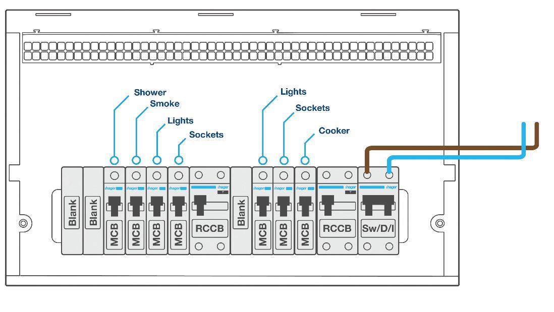
provide this protection. This will usually be the main switch and any RCCBs that are utilised within the enclosure.
Consumer units installed to a previous edition of BS 7671 may well contain 63 A RCCBs. Traditionally, diversity would have been used to assume that these RCCBs will not carry more than their rated current. However, Regulation 536.4.202 states that overload protection shall not solely be based on the use of diversity. This means that there must be an additional method for providing overload protection.
There are three options which can be used to apply this:
1. Ensure the rated current of the downstream devices does not exceed the rated current of the RCCB or switch. This option, however, could
easily be compromised should an additional circuit be added at a later time.
2. Ensure each RCCB and switch is suitably rated for the maximum possible incoming supply (i.e., 100 A). The sum of the individual circuit breakers is no longer important as the maximum current is restricted to 100 A by the supply cut-out fuse.
3. Use individual RCBOs for each circuit and not RCCBs. The rated current of the main switch is still of concern, but if 100 A, would be suitable due to the maximum supply available.
RCBO (Residual current operated circuit-breaker with integral overcurrent protection)
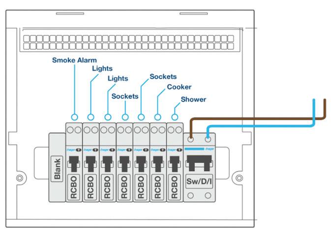
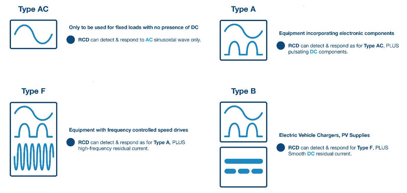
These are designed to make, carry, and break currents by mechanical switching and operate when the residual current reaches its set value. RCBOs can operate independently of any other protective device, and in addition to residual current protection, they provide protection against overloads and/or short-circuits.
RCBOs are commonly available 6 A to 45 A with B or C curve time/current characteristics. See Fig 2 for an example of individual circuit protection.
Regulation 531.3.3 states that different types of RCD exist and advises the appropriate device shall be selected depending on their behaviour in the presence of DC components.
Amendment 2 of the 18th Edition (2022) warned that Type AC RCDs shall only be used to serve fixed equipment where it is known that the load current contains no DC components.
This means that Type AC RCDs are not
classified as general purpose anymore; see Fig 3 for RCD Types and operating characteristics.
The issue of impairing (blinding) Type AC RCDs has become well-known in recent years, resulting in the widespread use of Type A RCDs. However, extra measures may be required when there is a known DC presence, for example in electric vehicle charging.
Regulation 722.531.3.101 requires each charging point to be individually protected, meaning it is not possible to use a spare way on a split-load consumer unit to supply electric vehicle charging points (EVCP).
Furthermore, unless a Type B RCD provides protection against DC fault currents, then Type A or F RCDs must be used in conjunction with a residual direct current detecting device (RDC-DD).
RDC-DD devices are often incorporated in Mode 3 charge points and can remove or initiate removal of the supply to electric vehicles in cases where
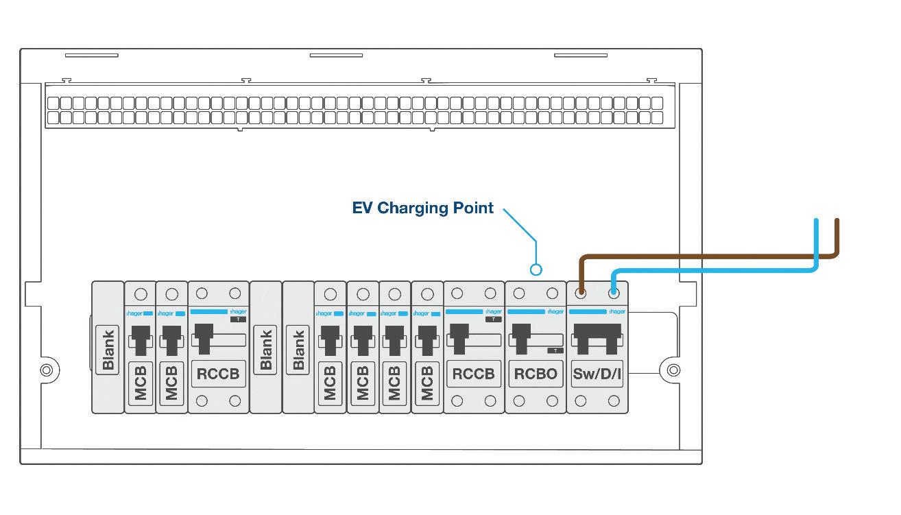
a smooth residual direct current equal to or above 6 mA is detected. The value of 6 mA was chosen to prevent impairing the correct operation of an upstream Type A RCD.
Imagine a Mode 3 charge point with built-in RDC-DD, incorrectly fed from a split load consumer unit Type A RCCB. It's possible that the charge point could add up to 6 mA of DC through the upstream RCCB in normal operation.
This is not a problem where individually protected, but any extra DC from other final circuits will now exceed what is deemed acceptable and safe for the shared Type A RCCB.
Where split load consumer units have high integrity configuration, it's possible to individually protect the EVCP, as illustrated in Fig 4
Because EV charging can take many hours with devices constantly loaded, it is important to check with manufacturers what measures are needed regarding applying rated diversity factors when taking into account the mutual thermal influences for the assembly arrangement.
Hager has conducted extensive testing in its ASTA RTL level 4 accredited laboratory (Telford factory) and can verify that a Hager 40 A RCBO or MCB is suitable to supply a 7 kW car charger when in the specific position that’s indicated in Fig 4
GET MORE DETAILS ABOUT HAGER’S FLEXIBLE ONLINE CPD ACCREDITED LEARNING COURSES BY VISITING: WWW.RDR.LINK/EBH023
Emergency lighting contributes to the safety of occupants during power outages or emergencies, providing illumination in critical areas, guiding occupants to exits safely and clearly.
It plays a critical role in the safety system of any building and as such, needs to be guaranteed to jump into action when required.
Proper installation and maintenance of emergency lighting systems are essential responsibilities, ensuring compliance with safety regulations and building codes. These systems are also a key aspect of risk management, protecting lives and property alike.
For electricians looking to learn more about emergency lighting, we’ll answer some key questions on its installation and ongoing maintenance.
This article should help build a core understanding of emergency lighting and mark a differentiation in the mind of the reader between aesthetic or practical lighting and emergency lighting.
QUESTION 1: How is emergency lighting powered?
Emergency lighting must be seen as a critical component of a safety system, not just a supplementary lighting feature. Its purpose is to provide illumination when
This article from the team at NVC Lighting gives an introduction to emergency lighting, its importance in the context of building safety and answers some key questions around its installation and maintenance.
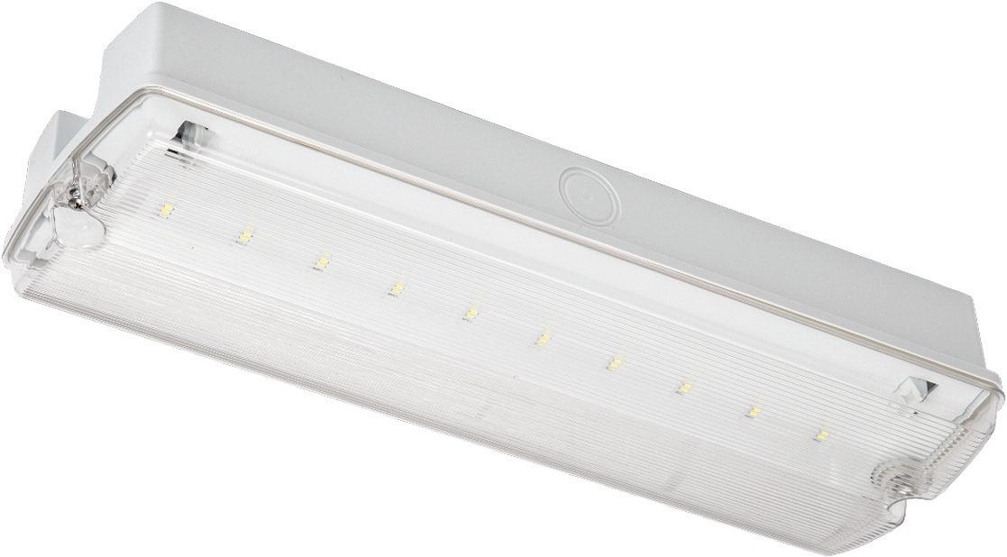
the main power supply fails, ensuring safe evacuation in an emergency.
Unlike standard lighting that might be controlled by a switch live, emergency lighting requires a permanent live power supply. This ensures that the lights are activated automatically if the main electricity is cut off, and that they remain functional, even when the building’s other lighting systems are turned off. This continuous power source is vital to safeguarding occupants during critical situations.
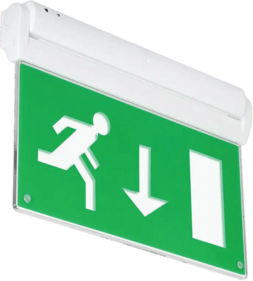
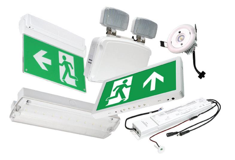
standards should emergency lighting adhere to?
The BS 5266 standard serves as a crucial code of practice for emergency lighting in the UK. While it is not a legal requirement on its own, adhering to this standard ensures compliance with all relevant legal obligations, including those within fire and safety regulations.
BS 5266 covers everything from system design and installation to maintenance and testing procedures, providing comprehensive guidelines for ensuring that emergency lighting is safe and effective.
Following this standard is essential to guarantee that the system performs as expected during emergencies, protecting both building occupants and employers from liability.
QUESTION 3: Whose responsibility is it to maintain emergency lighting?
Once the installation of an emergency lighting system is complete, it is crucial that a proper handover takes place to ensure the system is maintained correctly.
The building owner or manager typically takes responsibility for ongoing maintenance, but installers must provide thorough documentation.
There are two main types of testing systems: self-test and manual. Whichever method is used, proper upkeep is essential to ensure the lighting system remains functional in an emergency.
An emergency lighting system’s role in the context of a building is all about functionality –there isn’t an aesthetic
design consideration to be debated, and there isn’t a need for buildings to have the latest cutting-edge, pioneering technology.
What’s paramount though is that the system does exactly what it’s installed to do when it is needed.
Aside from this, the wider adoption of the ‘Golden Thread’ in construction means that it is going to be more important than ever before that safety information relating to emergency lighting is closely monitored and recorded.
Records of these test results, as well as any updates, faults or fixes, need to be accurately recorded and traceable in order to contribute towards creating a full picture of a building’s safety critical system.
Self-test systems automatically run checks and notify users of any faults, while manual systems require regular testing by personnel.
Testing and maintenance comes in the form of monthly ‘switch tests’ and an annual duration test. A switch test uses a momentary power interruption to show the lighting works under loss of power condition.
Duration tests are an annual requirement lasting three hours, where your primary light circuit must be switched off and your emergency lights left on for the full duration, with any defects to be reported and resolved as soon as possible.
On completion of a monthly or annual test, indicator LEDs and, where utilised, an audible buzzer will signal the status of the fitting.
This automated approach offers greater peace of mind, as well as reducing costs, but it is crucial that the information being received is utilised – and tracked – properly, so that any system failings are identified as quickly as possible and rectified.
LiFe PO4 (Lithium Iron Phosphate) batteries offer several advantages for emergency lighting systems.
They have a longer lifespan compared to traditional lead-acid batteries, often lasting up to eight years with proper maintenance and optimum conditions.
LiFe PO4 batteries are also more efficient, providing higher energy density in a lighter form, and they charge faster, offering a sustainable and cost-effective solution for emergency lighting systems.
An effective emergency lighting set-up consists of several key components, each serving a specific function to ensure safety during a power failure:
luminaires
Light fixtures designed to operate during an emergency, either through maintained (always on) or non-maintained (only on during power loss) configurations.
Illuminated signage showing clear paths to exits, which remain lit during emergencies, guiding people safely out of the building.
Battery back-up systems
Essential for powering emergency lights when the main power supply fails. Modern systems often use long-lasting LiFe PO4 batteries.
Either manual or self-testing, to regularly check that all emergency lighting is functioning as required.
Centralised panels that monitor the status of the emergency lighting system, allowing for system-wide checks and reporting on faults.
Each of these products works together to provide comprehensive emergency lighting coverage.

Electrical formulae and its application can be an area that apprentices, trainees and electricians can find both baffling and frustrating. However, it is essential in everything we do, from selecting the correctly sized protective devices, to designing and installing complex electrical installations.
I think back to my teaching days as an electrical lecturer and remember the look of dread on the learners’ faces as we covered science and principles involving maths subjects, such as algebra and trigonometry.
The availability of software applications for things such as circuit design have certainly made life easier, but it is extremely important to understand the basic building blocks of electrical formula to help us learn and become better electricians and designers.
Probably the most common and well-known formula is Ohm’s Law. In 1826, Georg Simon Ohm published details of an experiment in which he investigated the relationship between current, voltage and resistance. The formula is easily remembered by using the Ohms Law triangle as displayed in Fig 1.
Ohm’s Law states that if you have two of the values you can always find the third. In order to see this, we can use the following example:
Example:
“We have a circuit where the current is 32 A and we have a resistance of 0.5 Ω. What is the voltage?”
V = I x R, which gives us:
V = 32 x 0.5 = 16 V
The same method can be applied when
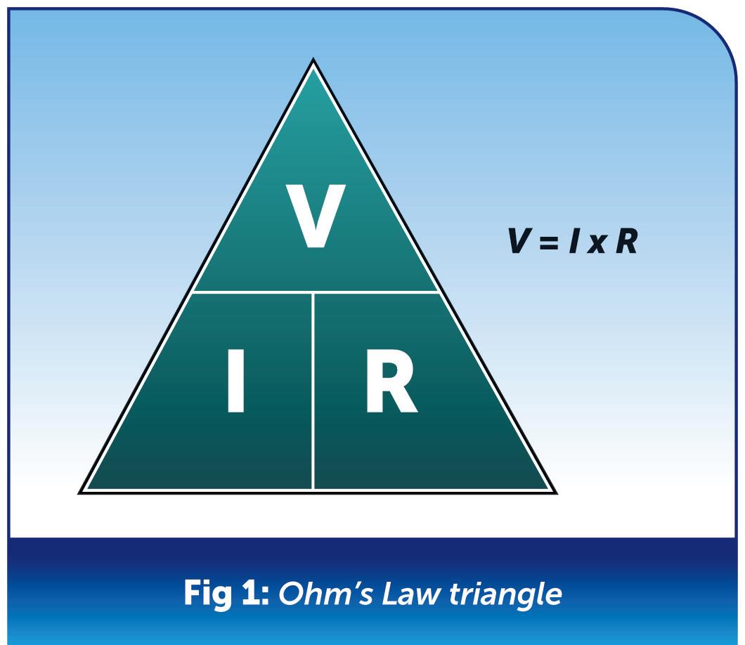
we need to calculate the power in a circuit. We use a slightly different triangle that contains the values power in watts (W), current in amps (I) and voltage (V) as shown in Fig 2.
Example:
“We have a circuit where the power is 3000 W and the current is 13 A. What is the voltage?”
V = P ÷ I, which gives:
V = 3000 ÷ 13 = 230 V
The power triangle is particularly useful for finding out the current of a particular appliance and then sizing a fuse accordingly.
We can also calculate the values of voltage, current, resistance and power using the handy formula wheel shown in Fig 3
Whilst handy triangles and wheels can help us with formulae, it’s always good to be able to do it ourselves using
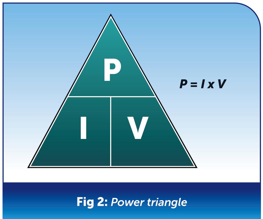
“By using a logical and methodical approach, electrical formulae and calculations can be a very useful tool to meet the requirements of BS 7671 and ensure that our electrical installations are safe and compliant.”
transposition. There are many ways of transposing a formula but the simplest way is to use the opposite rule
Rule 1: The opposite of addition (+) is subtraction (-)
Rule 2: The opposite of multiplication (×) is division (÷)
Rule 3: The opposite of squaring (x2) is square root (√)
Rule 4: The most important rule to remember is whatever you do to one side you need to do to the other side i.e. either side of the equals sign.
We can now apply this rule to find any value in a formula as shown below in the following examples.
Example 1:
“As we saw earlier Ohm’s Law states that V = I x R. However, what if we need to find the current (I)?”
Step 1: Firstly, we need to get I by itself, so we simply put I first in the rearranged formula: I =
Step 2: Next, we can move the original value that was before the equals sign (or on its own) to the other
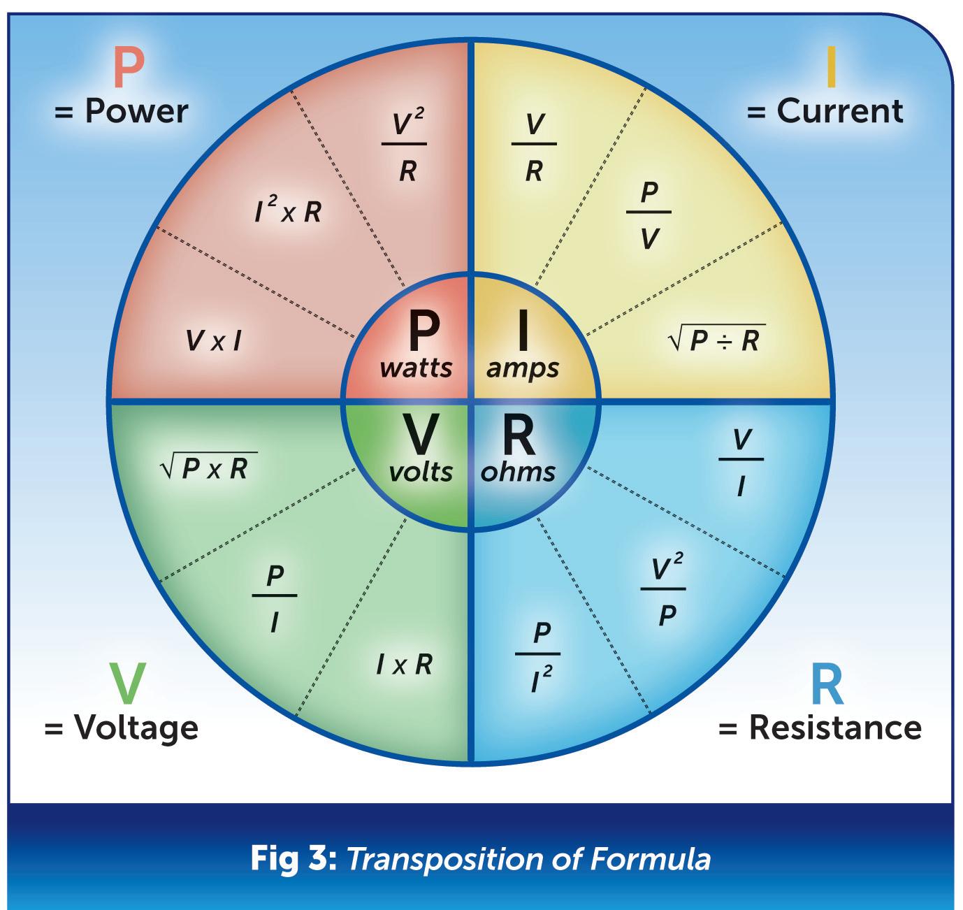
side of the equals sign, in this case it was V I = V
Step 3: Lastly, we take the remaining value, which is R, and apply opposite rule 2. This means that we move it from the top (multiply) to the bottom (divide) and underneath V: I = V or I = V ÷ R R
Example 2:
A harder example would be to find b from the formula: a2 + b2 = c
Step 1: Firstly, we need to get b2 by itself, so we simply put it first in the rearranged formula. b2 =
Step 2: Next, we can move the original value that was before the equals sign (or on its own) to the other side of the equals sign, in this case it was c: b2 = c
Step 3: Next, we take the remaining value, which is a2, and apply opposite rule 1. This means that the + (addition) now becomes(minus): b2 = c - a2
There is one more step to do because we need to find b not b2

Step 4: Therefore, using the opposite rule 3 to remove the square from b2 we apply square root.
However, whatever we do to one side, we need to do to the other side to give:
b = √c - a2
So far, we haven’t really applied these formulae practically to help us in our day-to-day work. Let’s look at a worked example using the adiabatic equation.
The adiabatic equation is very useful for finding a protective conductor size required for a circuit if we do not use the tabulated values in BS 7671.
It is important to establish the correct size of our protective conductor to ensure it has a large enough cross-sectional area (CSA). This is because it needs to carry any fault current to disconnect our protective device before the cable is damaged.
Adiabatic equation
S = √I 2 t k
S is the size or CSA of the conductor in mm2 (see Fig 4) t is the time in seconds
I is the fault current in amps k is a factor for temperature and resistivity etc. for different types of cable
However, for this example, let’s say that we already know the size of the conductor but we want to know the time it takes for the conductor to reach its limiting temperature (normally 70˚C for polyvinyl chloride (PVC) thermoplastic cable).
Firstly, we have to transpose or rearrange the original formula and get t on its own.
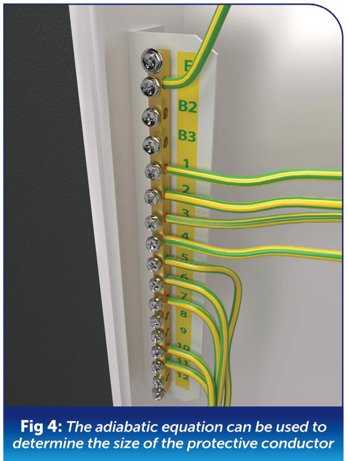
Example 3:
Step 1: We need to get t by itself. To make life easier it would be better to get rid of the k from the bottom right-hand side first. We do this by multiplying k on the right-hand side, which cancels out, but remember that we need to also do it on the left-hand side:
S x k = √I 2 t
Step 2: Next, we can get rid of the square root on the right-hand side by squaring it by itself and then do the same on the left-hand side:
S2 x k2 = I2t
Step 3: Next, we can get rid of I2 on the right-hand side by dividing it by itself and then do the same on the left-hand side, so we end up with:
“It is important to establish the correct size of our protective conductor to ensure it has a large enough cross-sectional area (CSA).”
“The adiabatic equation is very useful for finding a protective conductor size required for a circuit if we do not use the tabulated values in BS 7671.”
Let’s now apply some real-life values for a final circuit on a TN system with a maximum disconnection time of 0.4 seconds as follows:
S = 4 mm2 (CSA of the circuit protective conductor (CPC))
k = factor is 115
I = fault current is 650 amps
t = 42 x1152
650 2
t = 211600 422500
t = 0.5 seconds
So, we can see that our CPC will carry the fault current for 0.5 seconds before it is damaged. As our protective device will operate in less than that, within 0.4 seconds, the CPC size is satisfactory.
Conclusion
Hopefully, you can now see the value of formulae within electrical installations and circuit design. The maths side of working out circuit design doesn’t need to be something to shy away from. By using a logical and methodical approach, electrical formulae and calculations can be a very useful tool to meet the requirements of BS 7671 and ensure that our electrical installations are safe and compliant.
The age of properties causes numerous issues surrounding the presence of asbestos, with the substance found either within the fabric of the building or used in the Artex.
Asbestos was commonly used in Artex up until the early 2000s, when it was then banned due to health concerns. Even though asbestos is no longer used in Artex, there are still a number of health and safety concerns around painting over Artex as it could contain asbestos fibres. Therefore, it is also important to assess the risks before painting over any Artex.
Due to the range of risks associated with working with asbestos, and the lack of contractors qualified to work with it, housing providers across the country are installing battery powered (F1) alarms in place of mains powered (D1 & D2) alarms.
BS 5839-6 recommends the use of a D1 or D2 system which is defined as one or more mains powered detectors, each with a tamper-proof standby battery
supply. In contrast, an F1 system consists of one or more battery powered detectors powered by a tamper-proof primary battery.
The significant issue with an F1 system is the lack of secondary power supply, meaning that there would be no failsafe or notification of a failure. Hardwired alarms are connected to a consistent power supply and, as such, are known to be more dependable than battery-operated fire alarms. Furthermore, working fire alarms also double the chance of occupants escaping from a home fire (source: nationalsafetyinspections.co.uk)
One of the common obstacles regarding mains powered alarms would be interconnectivity of the alarms. The requirement for physical cables between alarms can be a major job if asbestos is present.
An alternative method
One method to overcome this is through Radio Frequency (RF) interconnectivity, which only requires power from a local lighting circuit, massively reducing the
inconvenience and upheaval associated with tricky wiring runs.
It is therefore important to recognise that the switch to F1 should only be used as a temporary measure, until the property can be properly assessed and upgraded to D1 or D2, as recommended by the British Standard.
Resident safety is paramount, and we should never take a backwards step when it comes to home life safety.
GET MORE SUPPORT FROM AICO ON STANDARDS AND LEGISLATION BY VISITING: WWW.RDR.LINK/EBH026
SECTION END
SCAN THE QR CODE TO CLAIM YOUR CPD CREDIT FOR THIS
SECTION OR VISIT: WWW.RDR.LINK/ EBH027


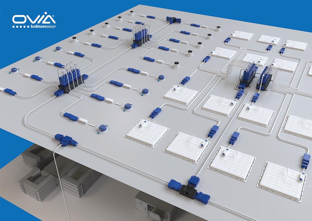
Jake Green, Head of Technical Engagement with Scolmore Group, looks at some of the problems associated with inferior quality connector products which don’t meet the required standards and therefore could represent a safety hazard.
Connectors are a method of joining one conductor to another and are capable of passing larger currents and voltages. A poor connection passing such currents can cause high resistance faults which could generate enough heat to degrade insulation which, in turn, can lead to a breakdown in the circuit and, in extreme cases, result in fire.
In light of this recent influx of inferior copies we would like to draw attention to the inter-compatibility of connectors and look at some of the standards that installation couplers should be conforming to, as well as some of the associated dangers and risks.
Standard IEC EN 61535 – relates to the installation of couplers intended for permanent connection in fixed installations. Clause 9 focuses on
dangerous compatibility.
Clause 9.1 An installation coupler system shall be designed and constructed so that unintended or improper connection is prevented.
It should be noted that unintended or improper connections include single pole connection, except for earth-to-earth connection. Compliance is checked by inspection and the following test. It shall not be possible to insert the installation male connector into the installation female connector resulting in a dangerous situation.
Engagement of the installation male and installation female connector is attempted in any unintended configuration using a force of 80 N for installation couplers marked as 10 A, 16 A, 20 A; or 120 N for installation couplers marked as 25 A and 32 A. The force shall be applied
on the same axis of the connection for one minute during which time the installation male and installation female connector contacts shall not engage.
Clause 9.2 It shall not be possible, within a given installation coupler system, to engage an installation male connector with an installation female connector:
● with a different number of live poles: exceptions may be admitted for installation female connectors which are specially constructed for the purpose of allowing engagement with installation male connectors of a lower number of poles, provided that no dangerous situation can arise.
● without earthing contact if the
installation male connector is an installation male connector with earthing contact.
● with different phase to neutral voltage ratings or different rated currents
Compliance is checked by the test according to 9.1.
Clause 9.3 Installation couplers of different systems from the same manufacturer shall not be dangerously compatible. Compliance is checked by the test according to 9.1.
Clause 9.4 Installation couplers according to this standard shall not be compatible with systems specified in standard sheets of IEC 60309, IEC 60320, IEC 60906 and with the national household plug and socket-outlet systems of the country where the product is placed on the market. Compliance is checked by manual test and in case of doubt by examination of drawings.
Ovia’s unique Flow connector is designed to prevent unintended or improper connection.
Incorrect polarity of connections could be considered as unintended or improper connection and could result in a dangerous situation.
If the polarity of a connection is incorrect then the appliance/fixture connected will either not work, resulting in time spent fault finding or, in some cases, appliance/fixtures can remain live, even if the power switch is turned off to them.
Clause 12 of the standard deals with construction
Clause 12.10 Installation couplers shall be provided with retaining means which engages automatically when the installation coupler or cap is connected, and which is capable of disengagement for disconnecting. It shall only be possible to render the means of retention ineffective by a deliberate or intentional act.
For installation couplers classified in accordance with 7.4.1 intended for installation in a readily accessible location the means of disengagement shall only be made by the use of a key or tool.
Compliance is checked by the following test:
The fully engaged installation coupler shall be subjected to a smooth axial traction force of 80 N for a period of one minute, during which the retaining device shall be fully engaged. The installation coupler shall not loosen or become disconnected.
Should the installation coupler loosen, this may result in the earthing integrity of a circuit not being maintained. In the unfortunate event that something goes wrong –such as a short or fault with an appliance –it may be possible to expose someone to a serious shock hazard, as it may impair or prevent operation of protective devices in the circuit.
We have highlighted some of the standards that installation couplers should be conforming to. Safety is a critical market requirement, and it is vital that manufacturers identify the required regulations and develop products that meet the required standards.
All of our products are independently third party verified to provide the reassurance and confidence that the products being sold or installed are safe and fit for the intended purpose. Not all manufacturers can say the same.
The Ovia Click Flow connector range is engineered to make the wiring of complex lighting circuits easier and safer using a combination of distribution hubs, managements boxes and the vast combination of connectors that make up the Flow range.
Frank Bertie, Managing Director at NAPIT, discusses bonding issues and extraneous-conductive-parts in electrical installations.
Bonding requirements of BS 7671
Whenever we have discussions, whether received on the NAPIT Technical Helpline, at NAPIT EXPO events, or on the NAPIT webinars, they normally involve main and supplementary equipotential bonding in all types of premises.
This article will examine the bonding practice in general and the requirements in BS 7671 for main equipotential and supplementary bonding.
So, what is bonding?
As we all know, bonding and earthing are not the same thing. Although the same green and yellow conductors are used in earthing and bonding, we should be aware that their functions are fundamentally different. The two are as different as chalk and cheese.
In BS 7671 Part 2 where the definitions are listed, earthing is defined as follows:
● Connection of the exposed-conductive-parts of an installation to the main earthing terminal of that installation.
It should be noted that bonding is not covered in its own right within the definitions, but the term ‘Bonding Conductor’ has been listed as ‘a protective conductor providing equipotential bonding’. So, this leads us to ‘Equipotential
bonding’, which offers a fuller explanation of the function of bonding, which is defined as follows:
● Electrical connection maintaining various exposed-conductive-parts and extraneous-conductive-parts at substantially the same potential (see also Protective equipotential bonding).
The use of protective earthing and protective bonding in electrical installations is one of the most widely used methods of giving protection against electric shock from the metalwork of an electrical installation that has become energised ‘LIVE’ due to the development of a fault.
This method is called Automatic Disconnection of Supply, which is abbreviated to ADS, and is described in Regulation 411.1:
(i) basic protection is provided by basic insulation of live parts or by barriers or enclosures, in accordance with Section 416; and
(ii) fault protection is provided by protective earthing, protective equipotential bonding and automatic disconnection in case of a fault, in accordance with Regulations 411.3 to 411.6.
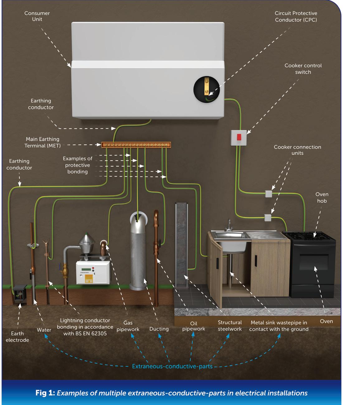
As a simpler method of describing this, bonding is the process of connecting the metalwork associated with an electrical installation with metalwork that is not associated with an electrical installation with green and yellow protective conductors of appropriate size.
Such metalwork defined in BS 7671 as exposed-conductive-parts are integral to the electrical installation and include the metal casings of equipment, such as containment, distribution boards and a range of appliances. This would also include accessories such as metal switch plates and metal socket outlets but would not extend to non-metallic accessories with metal screws.
Where we have other metalwork, which is defined in BS 7671 as extraneous- conductive-parts, that would consist of metallic water pipes, gas pipes and ducting.
The objective of equipotential bonding is to create an area or zone within an electrical installation where there is a single voltage throughout (voltage was formerly known as potential). A person receives an electric shock by touching or being in contact with two different voltages at the same time.
It is this difference in voltage which causes an electric current to flow through a person, resulting in the person experiencing an electric shock.
The requirements for carrying out equipotential bonding seek to remove or at least to minimise voltage differences within the electrical installation by creating an equipotential zone within those areas. In simple terms, equipotential means one

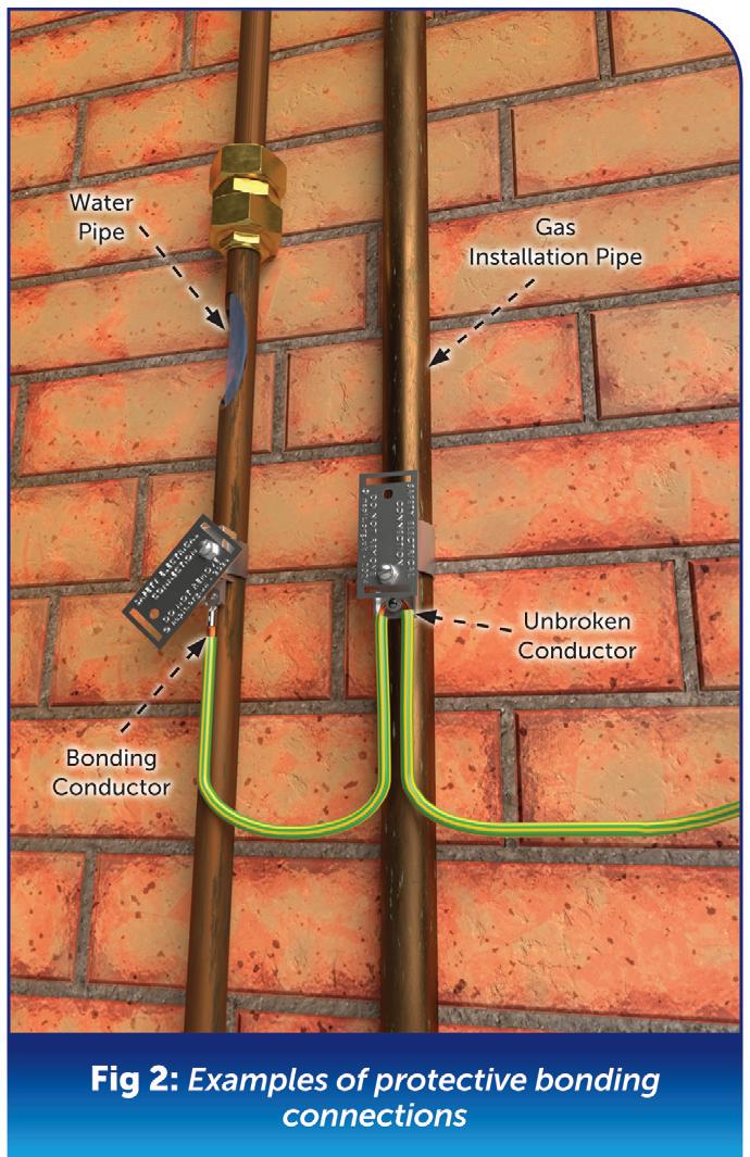
potential or one voltage. Therefore, it is evident that protective conductors used for earthing serve the purpose of carrying fault current.
Equipotential bonding conductors serve the purpose of providing protection by ensuring that all of the metalwork is of approximately the same potential.
Main bonding, or to give it its full title, main equipotential bonding, is required to be carried out on all metallic services and structures that fall within the BS 7671 Part 2’s definition of extraneous-conductive-parts, as shown in Fig 1
BS 7671 Regulation 544.1 outlines the requirements for main protective bonding generally, with Regulation 544.1.1 specifying the conductor sizes for the main protective bonding.
Table 1 shows these requirements regarding the cross-sectional area (csa) of the main protective bonding conductors when linked to the sizing of the main earthing conductor for TT/TN-S systems.
In determining the csa of the main protective bonding conductors, we need to consider the type of supply, since there are differences between TT/TN-S and TN-C-S systems.
Although the reliability of TN-S systems cannot be assumed to be purely separate earths in the current situation, the csa of the main protective bonding conductors in TN-S systems should
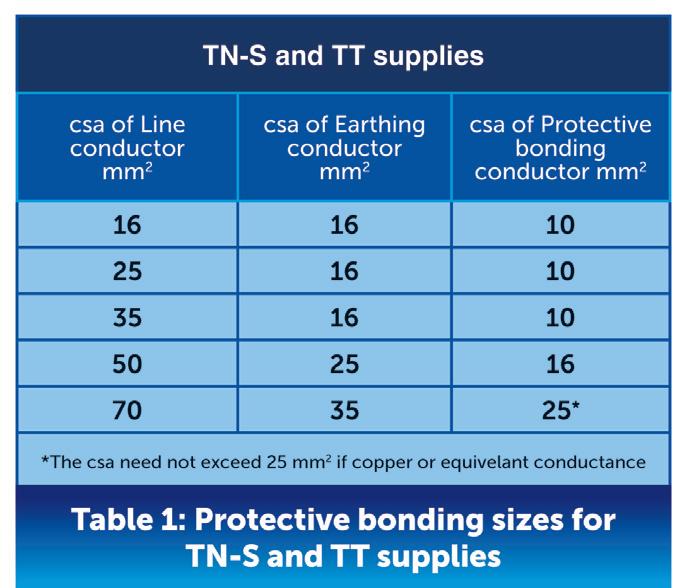
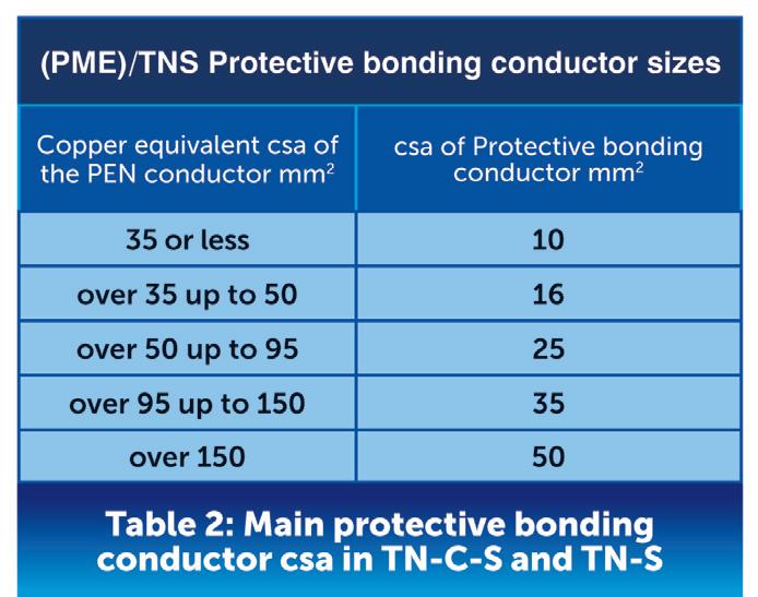
follow the requirements for TN-C-S as shown in Table 2
There are different options for the installation of main equipotential bonding conductors where they can be separately installed to each extraneous-conductive-part, several examples of these can be seen in Fig 2 Alternatively, they can be connected as a continuous main protective bonding conductor from the main earthing terminal to each extraneous-conductive-part without a break in the conductor.
As per Regulation 544.1.2, all main protective bonding connections shall be made as near as practicable to the entry point to the premises.
This also applies to the installation of meters, where the connection, where practicable, should be within 600 mm of the meter outlet union.
When sizing, installing, connecting and locating the main protective bonding conductors, it is imperative to consider the requirements of Regulation 544.1 in the design process.
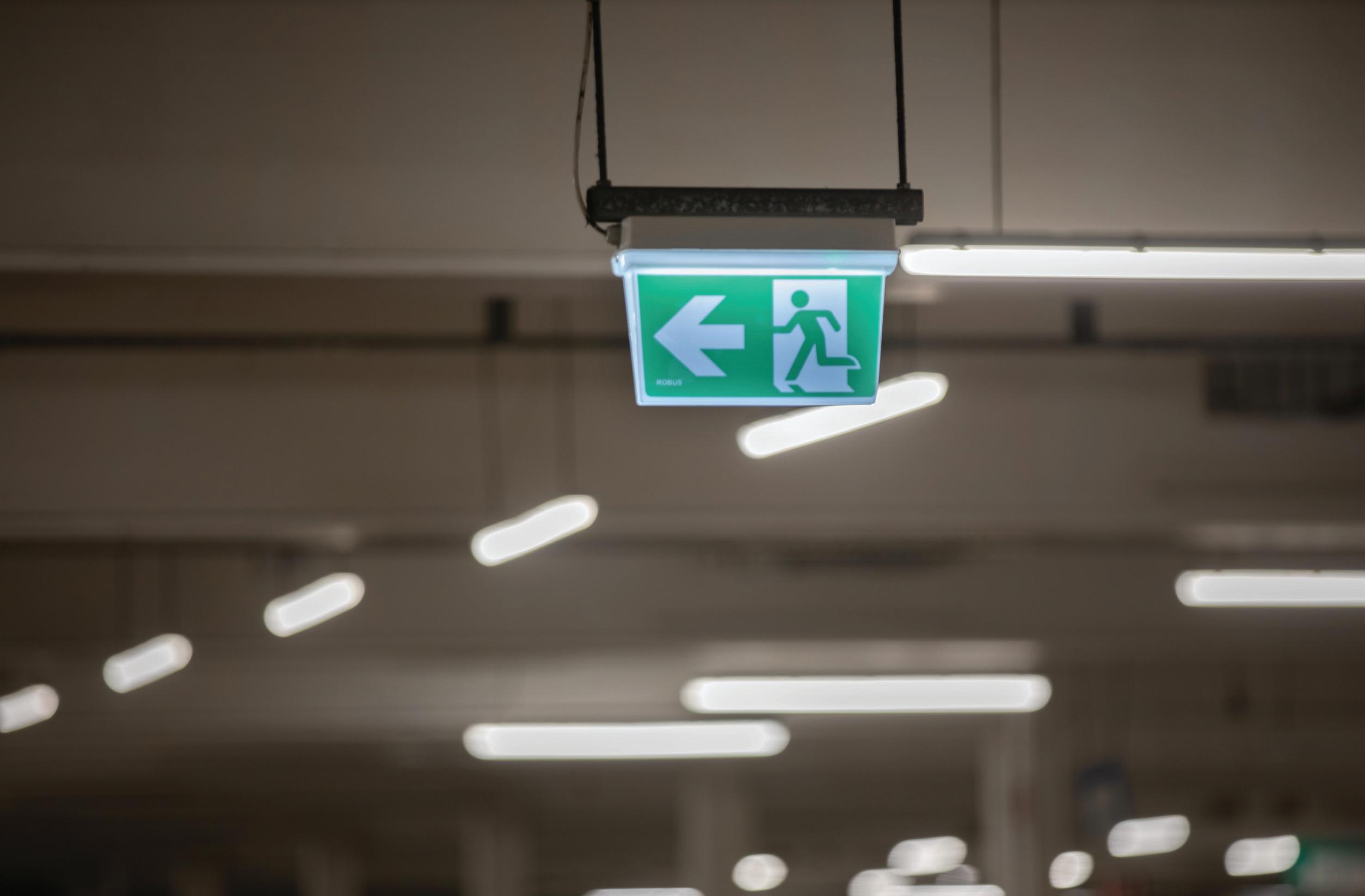
The experts at ROBUS offer some pointers on verifying the quality of the emergency lighting products you’re considering fitting.
You wouldn’t buy the cheapest parachute in the store, so why buy the cheapest emergency lighting? After all, both are designed as life-saving devices!
That said, it’s true that without knowing what to look for, it can be difficult to discern the difference in the quality of emergency lighting. The rule of thumb, “If it looks too good to be true (too cheap!), then it probably is,” will only take you so far.
So, how can you verify the quality of your emergency products?
The Lighting Industry Association (LIA) and Industry Committee for Emergency Lighting (ICEL) are making it easier than ever for electricians to identify high-quality lighting products through the enhanced ICEL Product Certification Scheme. This scheme provides independent verification of emergency products, ensuring that certified products meet stringent safety standards.
The rigorous review process consists of different tests and assessments, and for some lighting manufacturers, obtaining
this new certification will require a significant investment.
However, for companies that already have high quality standards embedded in the development of their emergency lighting, this will be a simple adjustment. For example, ROBUS has been incorporating the glow wire test into its product development process for years.
The glow wire test for emergency lighting, outlined by ICEL in alignment with international standards such as IEC
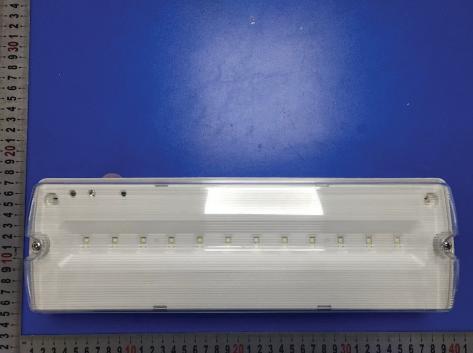
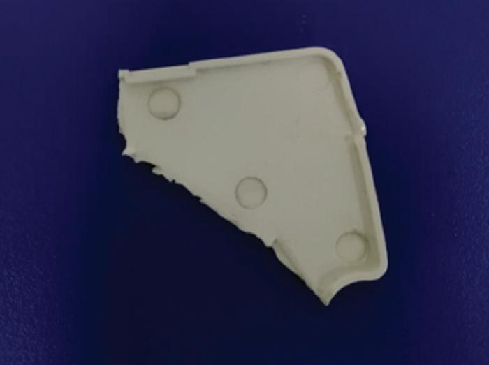
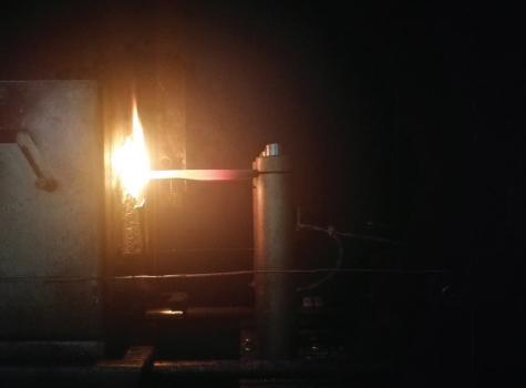
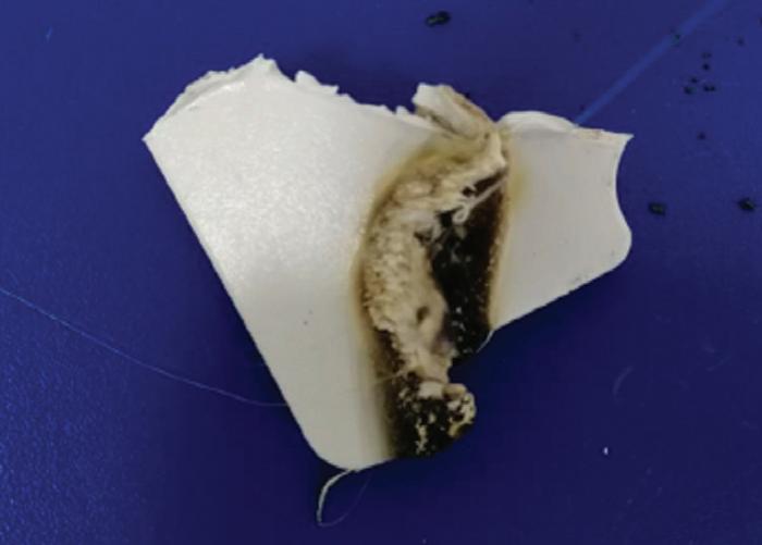
60598-2-22, is a vital safety evaluation. This test assesses the fire resistance of electrical components, focusing on the materials used in emergency lighting systems.
Let’s see why this matters…
Imagine a building experiencing an electrical fault that causes wires to overheat. In a worst-case scenario, the heat could cause nearby components to catch fire, potentially leading to a dangerous situation, especially in an emergency.
Now, consider that the building’s emergency lighting system needs to guide people to safety during this event. If the materials used in the emergency lighting system are not fire-resistant, they could ignite or melt, rendering the lights useless (even dangerous) when they’re needed most.
This is where the glow wire test becomes crucial. By ensuring that the components of emergency lighting systems can withstand high temperatures without catching fire, the test helps to prevent such failures.
Let’s take EBLANA, a popular bulkhead from ROBUS, as an example to understand how the glow wire test works in practice.
For any test or experiment, it is important to ensure standardised conditions for a fair assessment, establish agreed-upon acceptance criteria, and specify the test equipment.
Here’s how this was outlined in the official glow wire test documentation for the ROBUS EBLANA:
Parts are subjected to a test using nickel-chromium glow-wire heated to 850°C. The test apparatus and test procedure shall be those described in IEC 60695-2-11. Any flame or glowing of the sample shall extinguish within 30 seconds of withdrawing the glow wire, and any burning or molten drop shall not ignite the underlying parts specified in IEC 60695-2-11.
Acceptance criteria
Extinguish within 30 seconds and any burning or molten drop shall not ignite the underlying parts.
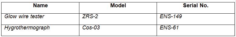
Once these elements are all in place, the test can begin. The test procedure is as follows:
● Heating the wire: the glow wire is electrically heated to 850°C.
● Application: the heated wire is pressed against the material being tested for a set duration, usually around 30 seconds.
● Observation: the material is monitored for any signs of ignition, how long the flame lasts, and whether any flaming material drips.
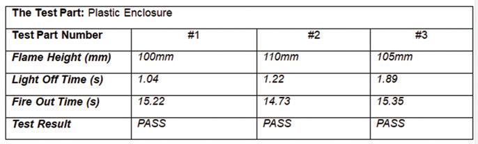
That’s a 100% pass result!
It's important to note that the French version of EN IEC 60598-1 requires a glow wire test with the wire heated to 850°C for luminaires intended for use in stairwells or horizontal travel paths. This 850°C standard is also recommended as best practice for emergency lighting on escape routes, as outlined in ICEL Schemes and I.S3217.
The glow wire test is just one part of the ICEL Product Certification Scheme review process. The scheme involves a detailed assessment of both the products and their accompanying technical documentation, ensuring that the manufacturers' claims are fully validated. It covers a broad range of emergency lighting products, including luminaires, control gears, and batteries. So, next time you’re stocking up on emergency lighting look out for the ICEL Certification mark – you might just save someone’s life.
BS 7671 permits an unfused spur (or cable branch) from a 30 A or 32 A ring final circuit supplying accessories conforming to the relevant part(s) of the BS 1363 series to be wired with thermoplastic (PVC) or thermosetting insulated copper line and neutral conductors of cross-sectional area as small as 2.5 mm² (433.1.204) where each accessory forming part of the ring final circuit itself is supplied via two such 2.5 mm² conductors. This article from the experts at NICEIC explains why this practice is acceptable.
Designers and installers will recognise that the current-carrying capacity of 2.5 mm² thermoplastic (PVC) insulated copper conductors is generally less than the 30 A or 32 A rated current of the fuse or circuit-breaker at the origin of the ring circuit, particularly once the installation method and any relevant installation factors have been taken into account.
This is also the case for cables employing thermosetting insulation where, additionally, they are selected on the basis of their conductor operating temperature not exceeding 70°C as is generally necessary for compatibility with the accessories to which they are connected.
Consequently, the circuit protective device cannot protect the conductors of the unfused spur against overload current; if the spur conductors were to become overloaded, this may result in damage to the insulation, sheath, the immediate surroundings of the cable, or to connected accessories, due to the
temperature of the conductors rising to above their rated value.
Why is it permitted to use 2.5 mm² conductors for an unfused spur?
Referring to regulation 433.1.204, the following conditions apply to the wiring of a ring final circuit:
● The current-carrying capacity of the cable, corrected for the particular installation conditions (IZ) must not be less than 20 A, and
● The circuit design, under intended conditions of use, should be such that the load current in any part of the circuit is unlikely to exceed the current-carrying capacity of the cable (IZ) for long periods of time (typically in excess of one hour).
Where this is the case, it can be taken that the condition given in indent (ii) of regulation 433.3.1 for the omission of overload protection is met.
It should be noted, however, that a conductor size of greater than 2.5 mm² may be required in order to meet voltage
drop limits, particularly for long cable runs (see Section 525).
What measures can be taken to make overload of the spur sufficiently unlikely for compliance with BS 7671? In general, it can be taken that the live conductors of a spur are not likely to carry overload current for long periods of time where the spur feeds only:
“Additionally, sufficient numbers of socket-outlets should be provided and suitably distributed throughout the installation to provide reasonable sharing of load current around the ring final circuit (553.1.7).”
● One single or one twin socket-outlet, or
● One or more items of fixed equipment supplied via a fused connection unit, or
● One or more socket-outlets supplied via a fused connection unit.
Additionally, sufficient numbers of socket-outlets should be provided and suitably distributed throughout the installation to provide reasonable sharing of load current around the ring final circuit (553.1.7).
What about the possibility of short-circuit?
Referring to indent (ii) of regulation 433.3.1, overload protection may be omitted based on the grounds that conductors will not be subjected to sustained overload, subject to said conductors being protected against fault current in accordance with the requirements of Section 434.
Using the adiabatic equation given in regulation 434.5.2, it can be seen that any of the 30 A or 32 A fuses or circuit-breakers (including those incorporated in RCBOs) listed in regulation 433.1.204 for use as the protective device for a ring final circuit will protect the 2.5 mm² live thermoplastic or thermosetting insulated copper conductors of an unfused spur against short-circuit current.
And what about earth-fault?
In order to determine whether the 30 A or 32 A protective device will protect the, typically, 1.5 mm² circuit protective conductor (cpc) within a 2.5 mm² BS 6004 flat twin & earth cable the adiabatic equation given in regulation 543.1.3 should be used.
This will show that any of the 30 A or 32 A fuses or circuit-breakers (including those incorporated in RCBOs) listed in regulation 433.1.204 for use as the protective device for a ring final circuit
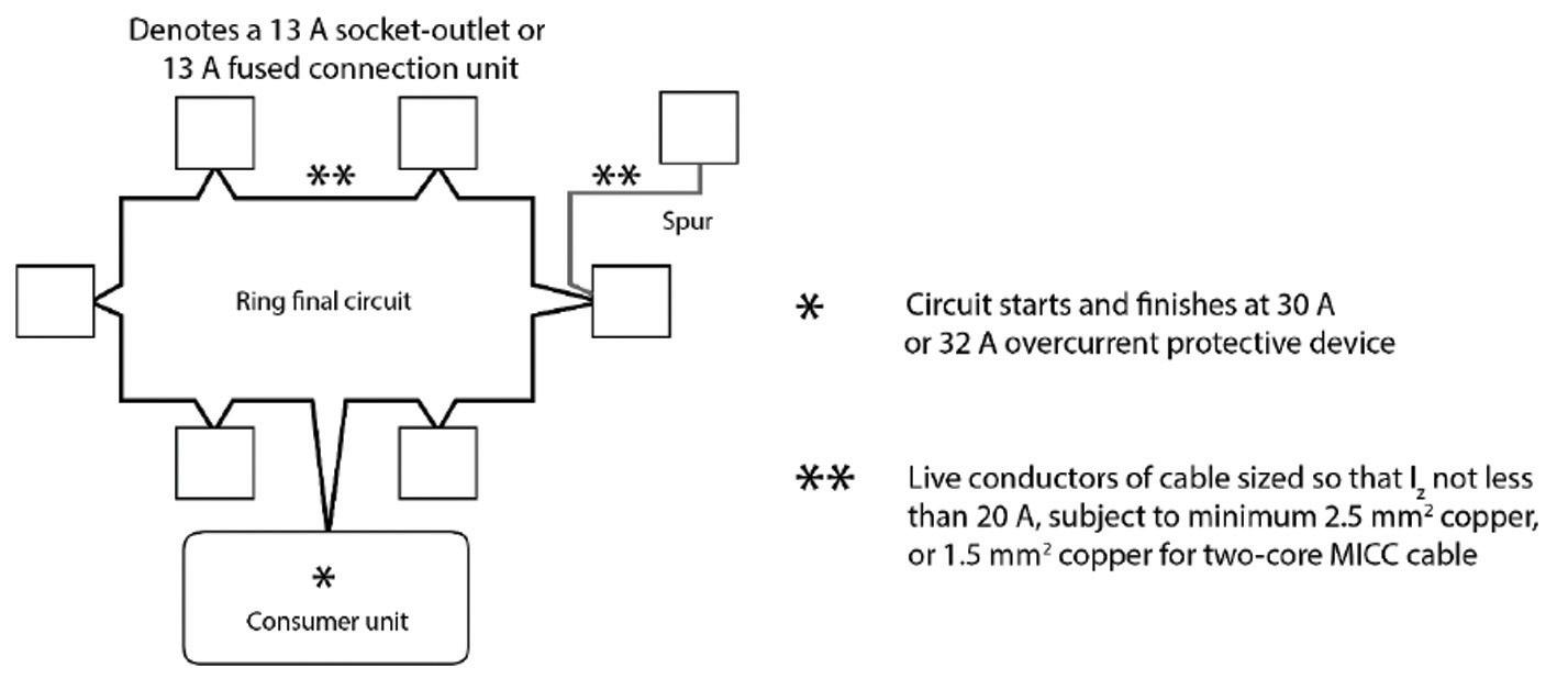
will protect the 1.5 mm² cpc, provided that the earth fault loop impedance (ZS) at the points supplied by the spur is within the maximum value required by BS 7671 to provide a 0.4 s disconnection time.
Further guidance on the installation of ring and radial final circuits for household and similar premises in accordance with regulation group 433.1 is given in Appendix 15 of BS 7671
Electrical Safety First, in conjunction with a number of industry partners, including NICEIC, have produced guidance on the minimum provision of electrical socket-outlets in the home which may be downloaded free-of-charge at: www.electricalsafetyfirst.org.uk/media /1204/guidance-on-minimum-provision -socketsv2.pdf
Summary
BS 7671 allows the use of 2.5 mm² thermoplastic and thermosetting insulated copper conductors for the connection of unfused spurs from 30 A or 32 A ring final circuits, provided certain conditions are met.
Although 2.5 mm² conductors typically have a lower current-carrying capacity than the circuit’s protective
“Electrical Safety First, in conjunction with a number of industry partners, have produced guidance on the minimum provision of electrical socket-outlets in the home which may be downloaded free of charge...”
device rating, regulation 433.1.204 permits their use when the circuit design ensures that load currents are unlikely to cause overload.
Measures such as, limiting the spur to supply single outlets of fixed equipment can prevent such overload. Applying the adiabatic equation demonstrates that the requirements for protection against short circuits and earth faults are met.
PAULO ALVES: I FOUND THIS GEM ON A RECENT EICR. 2 X SHOWERS ON ONE MCB ALERTED MY FEARS ORIGINALLY, AND THIS IS WHAT I UNCOVERED –LIGHTING TAKEN OFF THE SPLICED IN SUPPLY. HE’D ALSO CUT THE 10 MM TO GET 2 X CONDUCTORS INTO ONE TERMINAL. WHEN I CONFRONTED THE INDIVIDUAL, I WAS TOLD THAT HE DOESN’T DO ELECTRICAL WORK.

Within BS 7671 there’s a requirement for equipment to comply with British or Harmonised Standards. Where they do not, the designer or other person responsible will confirm that it is to the same degree of safety. It is obvious that the person responsible for this poor installation has no knowledge or understanding of electrical safety.
The junction box used is not suitable for external use; even with the on-site modification, duct tape does not feature in the IP rating table. The use of either pvc conduit or pvc waste pipe for the cable containment, again utilising duct tape for securing, is not a proprietary installation method,
The joint in a shower cable to allow branching off for an additional shower will lead to overloading of the circuit. Reducing the copper of a conductor to allow termination into a terminal again will have the additional risk, which could lead to heat build-up and potential fire.
Using a shower circuit to feed a lighting circuit from within the shower enclosure fails to meet the requirements for overcurrent protection. The lack of provision for cable restraints and the
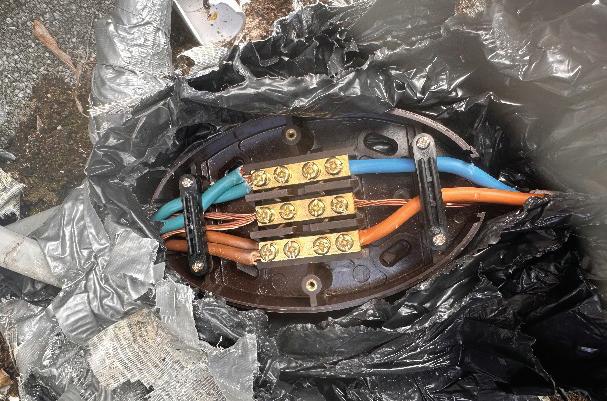
damage to the bottom left of the shower will allow ingress of water to the electrical terminals of the shower.
Lack of circuit protective conductor sleeving and the method of connection shows a disregard for electrical safety.
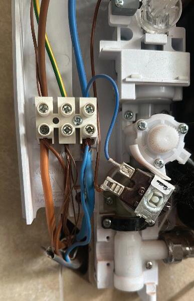
Therefore, the classification code would be a C1, Danger present – Risk of Injury, immediate remedial action required, due to the exposed live parts within a special location.


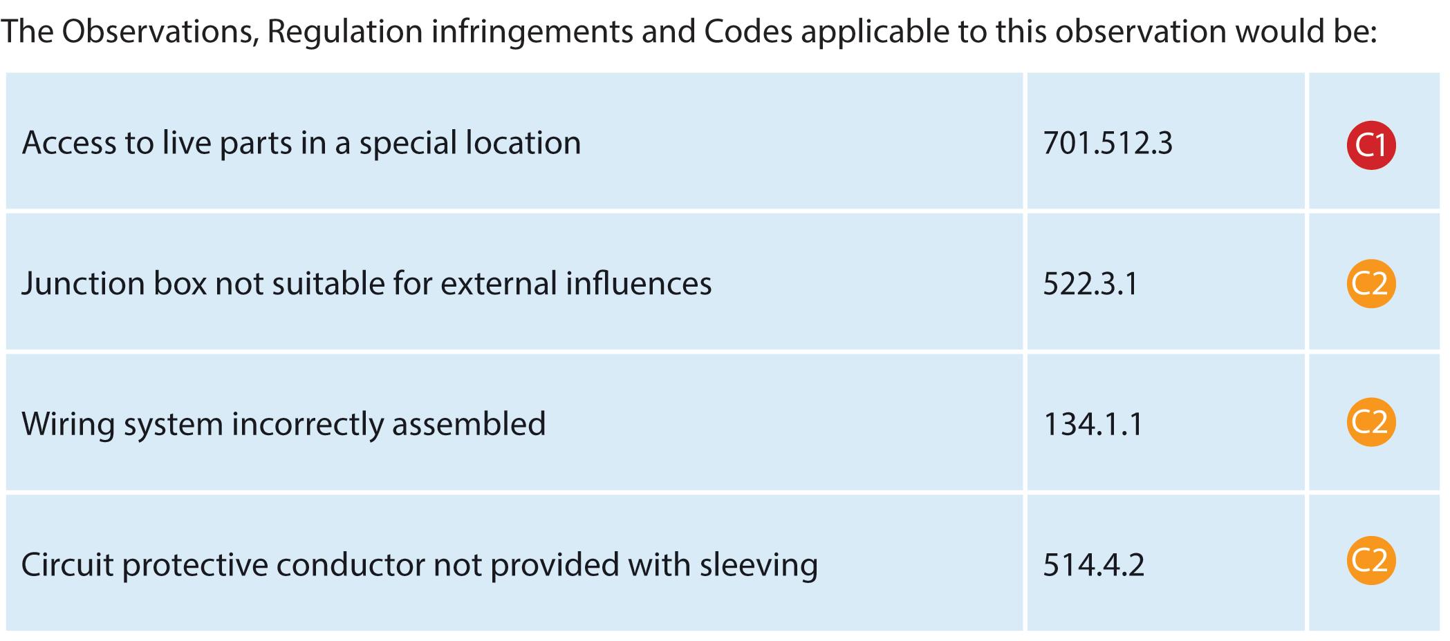


Updated for BS 7671:2018+A2:2022, NAPIT’s EICR Codebreakers publication is purpose-written to aid contractors, inspectors and clients, and now includes updates to align with Amendment 2 of the IET 18th Edition Wiring Regulations. The book is the perfect technical aid for electrical professionals and their customers.


Need help with cracking those all-important EICR codes? Every month the technical team at NAPIT will be studying your latest ‘Caught on Camera’ photos and offering advice on the next steps, should you find a similar installation. If you want the team at NAPIT to help crack your codes then send your pictures through to us at: pe@hamerville.co.uk

STEVEN DOBSON: THIS WAS FOUND ON A RECENT EICR – I’D IMAGINE THAT ISOLATING WILL BE A PROBLEM! ONE OF THE IMAGES SHOWS THE BOTTOM OF THE DB – I’M SURE THE BUSBAR SHOULD BE HERE?!
Every item of equipment is provided with manufacturer’s information, with the more complex sections having a detailed assembly sheet. It’s obvious that this installer didn’t follow such information, which has resulted in a dangerous situation.
This does appear to be an old installation (the plastic consumer unit gives it away), which is all the more worrying as the installation would have been in this state for some time with the client blissfully unaware of the dangers.
In residential premises the double-pole isolator is an essential item of equipment, as it allows a non-technical person to be able to safely isolate the supply. It would also be used for any fire and rescue services to be able to safely isolate when attending an emergency.
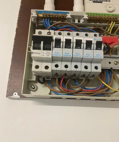
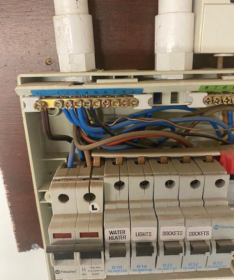
So, the double-pole isolator has effectively been bypassed where the busbar has been connected to the incoming line terminal on the top side of the consumer unit along with all the circuit-breakers.
There is excessive copper showing on the connections to the isolator and the circuit breakers. The use of red insulation tape as a means to prevent contact with live parts fails to meet product standard requirements. Although there is exposed live copper busbar on the consumer unit cover, there does not appear to be any unused entry holes or missing blanks, so this would not be considered as a C1.
The most dangerous aspect of this installation is that the isolation of the double-pole main switch will isolate the neutral conductor but not the line conductor, therefore energising the entire installation for the line and neutral conductors. It would provide the impression that the installation was de-energised with the equipment not functioning, but the conductors would still be energised and could cause an electric shock for anyone coming into contact with conductors or terminals.
Therefore, the classification code would be a C1 , Danger present – Risk of Injury, immediate remedial action required , for lack of safe isolation, incorrect installation of the link busbar, and a circuit protective conductor not sleeved where exposed live parts a re present.


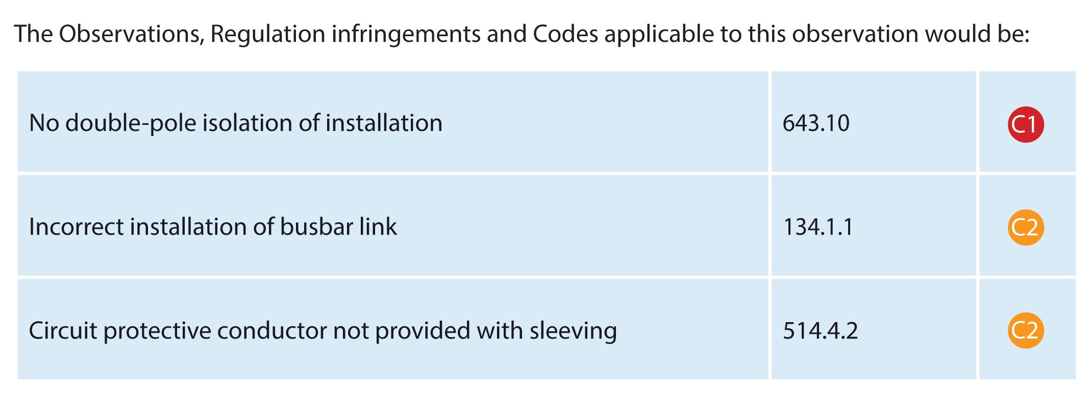

The A2:2022 18th Edition Codebreakers publication is priced at £22.00 (members) and £24.00 (non-members). It is available in both hard copy and digital versions * Price is VAT exempt and excludes postage and packaging.
It can be difficult for an electrical contractor to determine whether a single electrode will be sufficient to be able to gain an adequate value of resistance prior to its installation and test. Here, Jake Green Head of Technical Engagement, Scolmore Group, looks at how the earth electrode resistance might be improved as part of a planned approach to installation.
Earth electrode resistance is affected by several factors. These include:
● Climate conditions (wet/dry/frozen ground)
● Soil type (soil resistivity)
● Shape of the earth electrode (rod/plate/strip)
● Depth of burial
● Number of electrodes.
BS 7430: 2011+A1:2015 Code of practice for protective earthing of electrical installations provides recommendations and guidance
on meeting the requirements for the earthing of electrical installations.
Soil conditions
To calculate the expected earth electrode resistance generally assumes a homogenous soil (of a common type) rather than the more likely multiple layers as an electrode is driven into the ground.
Table 1 of BS 7430 (pictured on page 85) provides examples of soil resistivity for differing soil types. The table is no substitute for measuring the soil resistivity on-site.
The examples show that where the
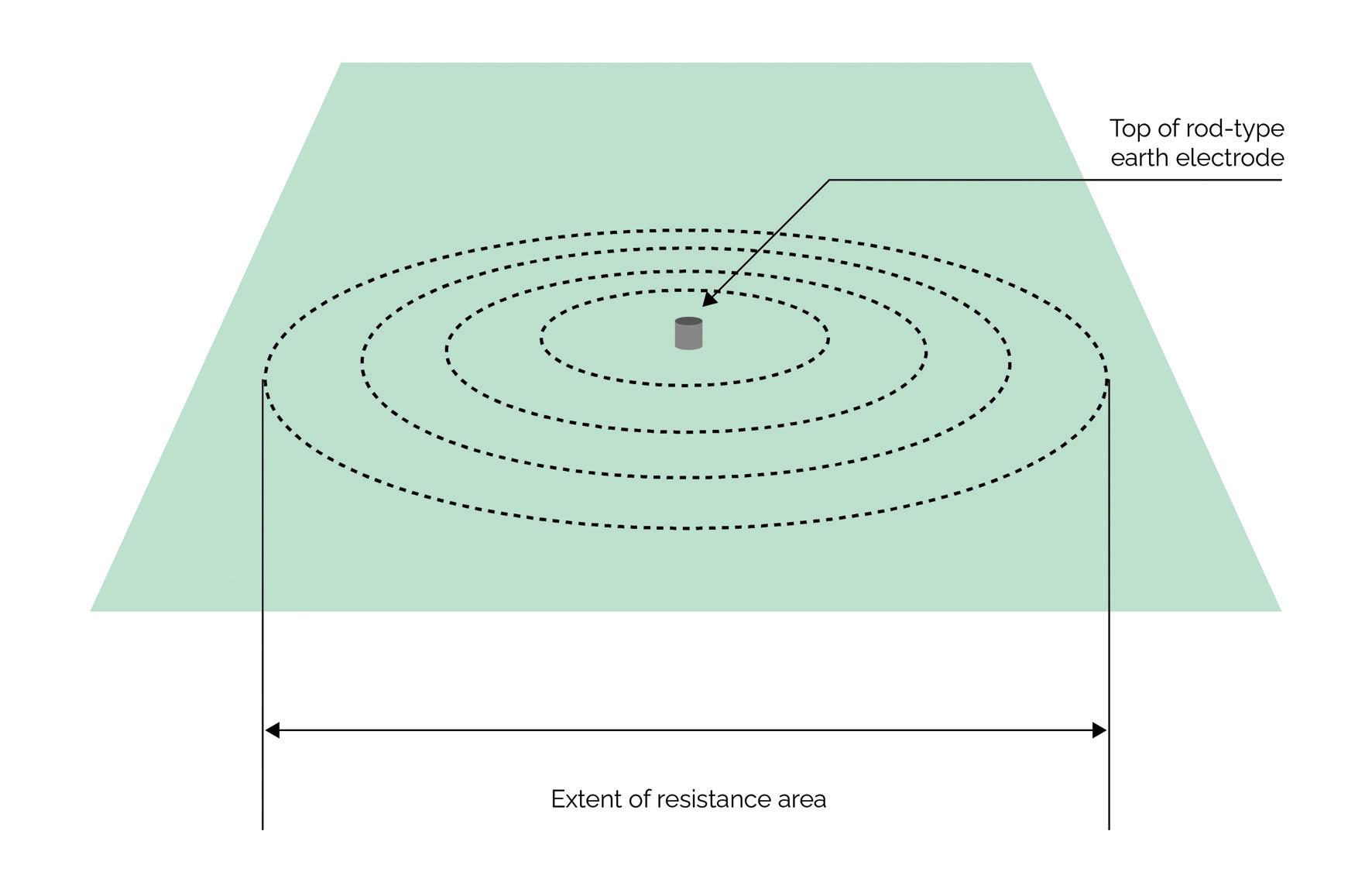
resistivity is naturally high (e.g. chalk/granite) it is difficult to create the conditions where the earth electrode resistance can be reduced significantly in value.
Earth electrode
BS 7430 recognises that the earth electrode must be robust, and that the earthing system remains safe.
The approximate resistance of a rod-type earth electrode may be calculated using: Where:
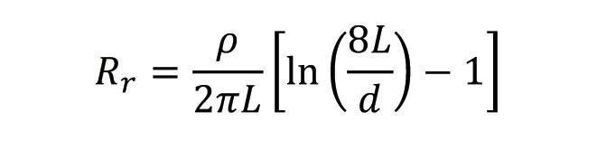
ρ = soil resistivity (Ωm)
L = length of the electrode (m)
d = diameter of the rod (m)
Calculation allows the designer and installer to determine before work is carried out whether, or not, a single electrode driven to a specific depth will be sufficient.
Example:
Consider doubling the depth of an earth rod from 2 m to 4 m in a chalk soil having a resistivity of 60 Ωm. The diameter of the rod is 38.5 mm.
2 m depth
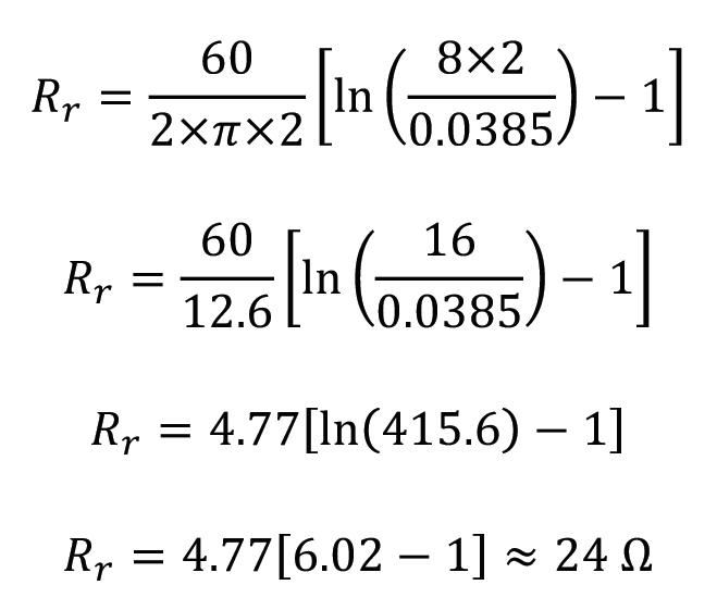
4 m depth
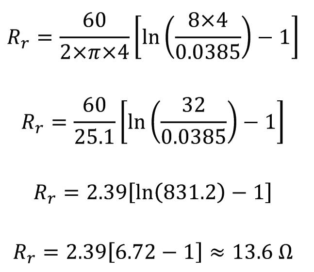
Based on this calculation, doubling the depth of the rod will improve the earth electrode resistance in a uniform soil, but will not halve the value.
Increasing the diameter of the rod will have very little impact on the overall earth electrode resistance; depth is the key factor in reducing the earth electrode resistance. The limiting factors on increasing the depth of an earth rod are mechanical strength as the rod is driven into the ground, and the varying soil strata.
There will be times, for instance with the
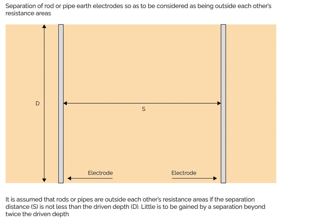
earlier example in chalk, where it isn’t possible to drive an earth rod deeper to reduce the earth electrode resistance. Where a reduction in earth electrode resistance is required, multiple earth electrodes (rods/plates etc.) can be installed in parallel with one another.
Where the soil is of a similar nature and where the electrodes are installed outside of the resistance area of each rod, the approximate resistance is the reciprocal of the number of rods employed.
Consider the previous example where the resistance was 24 Ω for an earth rod at a depth of 2 m. If a second rod were to be installed at the same depth and at, say, 6 m from the original rod, the resistance would fall to approximately 12 Ω (1/2). Were a third rod to be added the resistance would fall to approximately 8 Ω (1/3).
It is assumed that rods or pipes are outside each other’s resistance areas if the separation distance is not less than the driven depth. E.g. if the driven depth is 2 m then the separation distance should be at least 2 m. Little benefit exists once a distance of twice the driven depth exists.
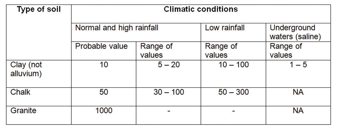
There are a series of formulae in BS 7430 to aid the designer in determining the most effective configuration for parallel electrodes, plates, mesh or strip electrodes. Figure 15 in BS 7430 highlights five such configurations, including:
● Triangular (three rods)
● Two strips at right angles
● Three strips set at 120° meeting at the star point
● Four strips set in a cruciform, and
● Square (four rods at each corner).
Conclusion
There are other methods of reducing the resistance of the earth electrode including, for example, the use of structural steelwork and encasing electrodes in low resistivity material. However, these methods are beyond the scope of this article.
Prior assessment of the proposed installation method and selection of electrode will enable the designer and installer to avoid a ‘hit and miss’ approach to the earthing of installations using earth electrodes.
SECTION END SCAN THE QR CODE TO CLAIM YOUR CPD CREDIT FOR THIS SECTION OR VISIT: WWW.RDR.LINK/ EBI044