4 minute read
DC Motor Controller—The Lesson of the Jones Switch


releasing the pedal means the motor is off (no creep). Pressing the pedal to a certain point sets a certain motor voltage, which means a certain speed. Pressing hard gives you a constant rate of acceleration (because the controller is in current limit; constant current 5 constant torque). Release the pedal, and it simply coasts (unless you have regenerative braking, in which case you can configure what it does).
DC Motor Controller—The Lesson of the Jones Switch
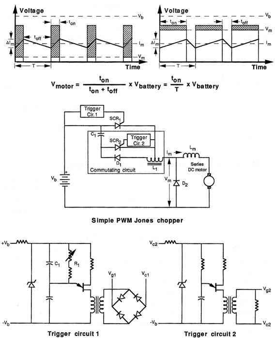
The easiest way to vary the DC voltage delivered to a DC motor is to divide its steady, nonvarying DC component into smaller pieces (see Figure 7-1). The average of the number or size of these pieces will be a resultant DC voltage that the motor “thinks” it is receiving. At the top left of Figure 7-1, the value of the voltage delivered to the motor is
Vmotor 5 ((ton)/(ton
1 toff)) 3 Vbattery 5 (ton/T) 3 Vbattery 5 KdcVb
(1) This equation shows that the voltage delivered to the motor is proportional to the amount of time the pulse is on versus the total length of the period. As toff >> t on in the left-hand graph, the average voltage (V) the motor receives is only equal to a small
Figure 7-1 Summary of Jones switch PWM chopper controller characteristics.
value. But in the right half of the graph, ton >> toff and V m is a much larger value—nearly equal to Vb—for the battery voltage. If you vary ton while holding T (the total period) constant, you have the principle of pulse width modulation or PWM. (If you vary T while holding ton constant, you have frequency modulation.) For a fixed ratio, a duty cycle of Kdc might be defined (far right or the equation above). PWM, or chopper control, as it is customarily called, allows you easily to control a DC motor by electronically chopping the voltage to it.
The earliest solid-state DC motor chopper controllers used SCR devices. These were technically primitive compared to today’s solid-state controllers, but typically offered greater efficiency, faster response, lower maintenance, smaller size, and lower cost than the motor-generator sets or gas tube approaches they replaced.
The Jones chopper circuit shown in the middle of Figure 7-1, adapted from an early GE SCR manual, is one of the simplest variations. Earlier, similar PWM circuits were also built in transformerless style using transistors. The Jones chopper is easy to look at and analyze, and its basic lessons apply to all PWM controllers.
It might be viewed as:
• An SCR (SCR1) controlled by a commutating circuit (SCR2 and trigger circuit 2) that controls the t on/toff time and a trigger circuit (trigger circuit 1) that controls the period T or frequency. • The diode D2 connected across the series DC motor’s terminals—usually called a free-wheeling diode—performs two important functions in this and other circuits where the pulsed output is inductive. • It “smooths” motor current I m and enables it to continue to flow when SCR1 is not conducting (top of Figure 7-1), and prevents the inductive-current-generated high-voltage spikes, which could potentially damage the transistors, from appearing across the motor when SCR1 is turned off. • Diode D1 prevents the L1–C1 combination from oscillating. Other than the SCRs and diodes, the key circuit elements are the center tapped autotransformer (both windings have the same number of turns, inductance, etc.), whose inductance is simply labeled L1 in Figure 7-1, the capacitor labeled C1, and the combined series motor and external inductance labeled L m .
The frequency of the chopper is controlled by the R1–C1 combination (where R1 is the sum of the fixed and variable resistors in that branch of the circuit) in trigger circuit 1 shown at the bottom left of Figure 7-1. In this case, a unijunction transistor forms the heart of a relaxation oscillator whose period is controlled by the RC time constant such that f 51/(R1C1) where R is resistance in ohms and C is capacitance in farads.
For a 2-kHz chopping frequency, you might choose C1 5 0.1 µF,
R1 5 1/(2 3 103 3 0.1 3 10–6) 5 5 3 103 5 5 kilohms
The switching frequency in a modern controller is derived from a crystal, not an RC oscillator. Stability under varying load and environmental conditions becomes more critical as power levels increase. This rudimentary example is simply for demonstration purposes.
From a design standpoint, the important elements in the circuit are
• The battery voltage Vb • The maximum motor current I m to be commutated
• The turn-off time of SCR1 • The voltage rating of SCR1 • The values for C1, L1 • The value for L m to minimize the ripple current in the motor armature DI m .
Motorola still has this product, which is now made by ON Semiconductor (www. onsemi.com/pub/Collateral/MC33033-F.PDF).
These are the basics. You have a highly modular, very superior solution to the Jones chopper, and you aren’t even breathing hard. As newer components are introduced, you can take advantage of them just by plugging them into the drive or power stages. You can easily change the frequency or even the motor speed control circuitry if it suits your purposes better.
As for the options, in Figure 7-2 there are two additional circuit boxes:
• Current limit control • RPM feedback control
Current limit control monitors motor armature current 1m and feeds a signal back to the shutdown command input on the PWM chip if it goes beyond a preset level.
The Jones chopper circuit was a popular early electric vehicle controller, even though it was an incomplete circuit. Like equivalent circuits of its vintage, it was inexpensive and easy to make (with relatively few components).
However, the disadvantages almost outweigh buying off-the-shelf controllers. They are relatively unsophisticated. Jones Chopper is even potentially dangerous to your series
Figure 7-2 Real controller design using LM3524.

