1 minute read
Mounting and Testing Your Electric Motor


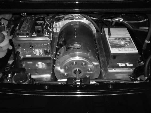
Figure 10-13 See how the motor is mounted into the compar tment from Figure 10-9.
Hubs (with or without pilot bearing, etc.) are going to differ widely in size and shape for different vehicle, transmission, and motor types, yet their function is the same. You must determine what you need in your particular case. Call KTA Services, Jim Harris, or your local mechanic to help you if you’re not sure. This is not the time and place to be shy.
In Figure 10-13, Paul Little created this great compartment that allows the motor to fit very nicely into the compartment.
Mounting and Testing Your Electric Motor
Depending on your accumulated skill and luck, your motor installation can either go smoothly the first time or involve several cut-and-try iterations. The basic approach is to mount the hub on the motor, attach the motor to its adapter plate, attach the flywheel to the hub, measure the critical distance to make sure it’s exactly the same as it is for the internal combustion engine (add spacers as needed, etc.), and then attach this completed assembly to the transmission. The winch used to take out the internal combustion engine is probably the easiest way to install your motor assembly into your vehicle (the completed assembly weighs upwards of 150 lbs. with a 20-hp series DC motor), but a floor jack (elevate the front of the vehicle on jack stands first) or engine-lifting dolly will also work. The installation step is basically the reverse of the removal step: attach the assembly at two points, then slide the motor up and toward the transmission until the shafts are in alignment. When everything fits exactly, tighten the bolts on the transmission and on the motor mounts.
For a quick test, first jack up the vehicle so its front- or rear-drive wheels are off the ground. Then put a 2/0 cable in place across the motor’s A2-S2 terminals. Attach

