
4 minute read
Construction
74 Hacking Electronics
use higher-brightness LEDs or power the project from a lower voltage. If you do decide on this, recalculate the values for R3 and R4 and try it out on the breadboard layout. The 555 timer IC needs a supply voltage between 4.5V and 16V, and the output can supply up to 200mA.
Construction
Step 1. Cut the Stripboard to Size
There is no point in having a large bit of stripboard with just a few components on it, so the first thing we need to do is cut the stripboard to the right size. In this case, it’s ten strips each of 17 holes. Stripboard doesn’t actually cut very well. You can use a rotary tool, but wear a mask because the dust from the stripboard is nasty and you really do not want it in your lungs. I find the easiest way to cut stripboard is actually to score it with a craft knife and metal ruler on both sides and then break it over the edge of your work surface.
Score it across the holes, not between them. When the board is cut, the copper underside will look like Figure 4-23.
Figure 4-23 A stripboard cut to size
Step 2. Make the Breaks in the Tracks
A good tip is to use a permanent marker and put a dot in the top left corner. Otherwise, it is very easy to get the board turned around, resulting in breaks and links being put in the wrong place.
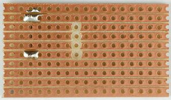
To make the breaks, count the position in rows and columns of the break from the top of the board layout and then push a bit of wire so you can identify the right hole on the copper side of the stripboard (Figure 4-24a). Using a drill bit, just “twizzle” it between thumb and forefinger to cut through the copper track. It usually only takes a couple of twists (Figure 4-24b and c).
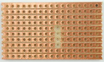
When you have cut all four breaks, the bottom side of the breadboard should look like Figure 4-25. Check very carefully that none of the burrs from the copper have lodged between the tracks and that the breaks are complete. Photographing the board and then zooming in is a great way of actually checking the board.
CHAPTER 4: LEDs 75

(a) (b)

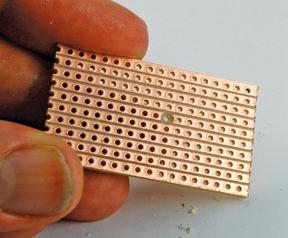
(c) Figure 4-24 Cutting a track on stripboard
Figure 4-25 The stripboard with breaks cut
Step 3. Make the Wire Links
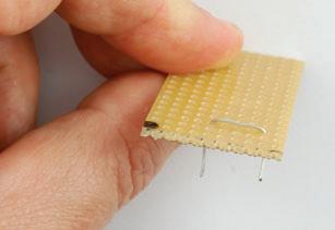
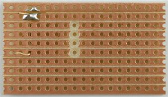
A golden rule of any type of circuit board construction, including when using stripboard, is to start with the lowest-lying components. This is so that when you turn the board on its back to solder it, the thing being soldered will stay in place through the weight of the board. In this case, the first thing to solder is the links. Strip and cut solid-core wire to slightly longer than the length of the link. Bend it into a U-shape and push it through the holes at the top, counting the rows and columns to get the right holes (Figure 4-26a). Some people get very skilled at bending the wires with pliers to just the right length. I find it easier to bend the wires with a bit of a curve so they will kind of squash into the right holes. I find this easier than trying to get the length just right from the start. Turn the board over (see how the wire is held in place) and solder the wire by holding the iron to the point where the wire emerges from the hole. Heat it for a second or two and then apply the solder until it slows along the track, covering the hole and wire (Figure 4-26b and c). Repeat this process for the other end of the lead and then snip off the excess wire (Figure 4-26d and e). When you have soldered all the links, your board should look like the one in Figure 4-27.
76 Hacking Electronics
(a) (b)

(c)
(e) (d)
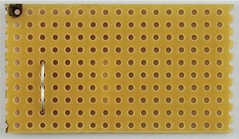
Figure 4-26 Soldering the links
Step 4. Resistors
The resistors are the next lowest components to the board, so solder these next, in the same way as you did the links. When they are all soldered, the stripboard should look like Figure 4-28.


