1 minute read
You Will Need
CHAPTER 9: Audio Hacks 225
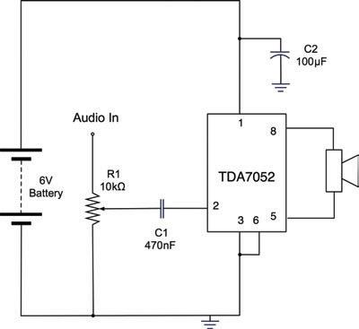
Figure 9-14 A typical TDA7052 amplifier schematic
An alternative to making your own amplifier is to buy a ready-made module. You will find these available for a wide range of different powers and in mono and stereo configurations. eBay is a good source for such modules, as are SparkFun (BOB-11044) and Adafruit (product ID 987). These modules often use an advanced type of design called “class-D,” which is far more efficient in its use of energy than the module we are going to build. Figure 9-14 shows the typical schematic for a TDA7052 amplifier. R1 acts as a volume control, reducing the signal before amplification.
C1 is used to pass the audio signal on to the input to the amplifier IC without passing on any bias voltage that the signal may have from the audio device producing the signal. For this reason, when you use a capacitor like this, it is called a coupling capacitor.
C2 is used to provide a reservoir of charge that can be drawn on quickly by the amplifier when it needs it for very rapid changes in the power supplied to the speaker. This capacitor should be positioned close to the IC.
You Will Need
To build the amplifier module, you will need the following.
Quantity Name Item Appendix Code 1 IC1 TDA7052 S9 1 R1 10kΩ variable resistor K1, R1 1 C1 470nF capacitor C3 1 C2 100µF capacitor K1, C2 1 8Ω speaker H14 1 Stripboard H3


