34 minute read
Capacitive-Touch Gain-Controlled Personal Amplifier
from CC_261_201
by Hiba Dweib
FEATUREARTICLE
Advertisement
Two Camosun College graduates designed an inexpensive do-it-yourself personal audio amplifier. The design features capacitive sensing, digital-signal mixing, and high-quality sound.
When did you stop thinking about how consumer and modern to get kids excited to build it, but without being too expensive or electronics looked on the outside and ask yourself what happens on the inside? For many consumers, unfortunately, this epiphany will never take place. Most people will live their lives buying, using, and disposing of electronics without ever knowing how they actually work. But for some, this will happen naturally and their curiosity will give them the energy to explore to their hearts’ content. We intend to engage and inspire these inquisitive-minded tech enthusiasts.
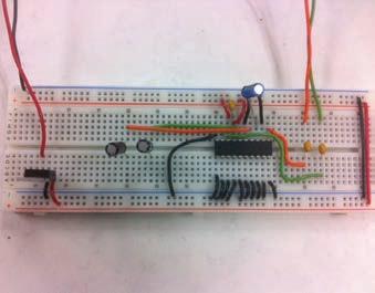
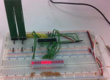
While studying at Camosun College in Canada, we were tasked with creating a “no-experience-needed” electronics kit that would appeal to middle/high school students. The students would be given a crash course in soldering, so we had to make it as solder-friendly as possible. For this reason, we weren’t allowed to use surface-mount components. We could only use through-hole components. This was because the last thing we needed was a bunch of eighth graders, buzzing on sugar, armed with heat guns! The kit also needed to be sleek time consuming. Since every kid and his dog owns an iPod, MP3 player, or some other type of personal audio device, it made sense to build a personal audio amplifier (see Photo 1). The tough choices were how we were going to make it stand out enough to attract kids who already own high-end electronics and how we were going to do it with a budget of around $40.
SHOW ME THE PARTS
Our first concern was how we were going to mix and amplify the
low-power audio input signals from iPods, microphones, and electric guitars. We decided to have a couple of different inputs, and we wanted stereo and mono outputs. After doing some extensive research, we chose the Cypress Semiconductor CY8C29466-24PXI programmable system-on-chip (PSoC). This enabled us to digitally mix and vary the lowpower amplification using the programmable gain amplifiers and switched capacitor blocks. It also came in a convenient 28-pin DIP package that followed our design guidelines. Not only was it perfect for our design, but the product and a) b) Photo 1a—This is the capacitive-touch stage of the personal audio amplifier. b—Here you see the power-amplification stage of the personal audio amplifier.
developer online support forums for all of Cypress’s products were very helpful.
Let’s face it: mechanical switches and potentiometers are fast becoming obsolete in the world of consumer electronics (not to mention costly when compared to other alternatives). This is why we decided to use capacitive-touch sensing to control the lowpower gain. Why turn a potentiometer or push a switch when your finger comes preequipped with conductive electrolytes? We accomplished this capacitive touch using Microchip Technology’s mTouch Sensing Solutions series of 8-bit microcontrollers. The project was originally done on the PIC16F1939 (40-pin DIP) microcontroller, but after we were confident that we could implement it on a smaller chip, we ended up going with the PIC16F1938 (28-pin DIP) microcontroller. This
SCBLOCK Mic in PGA Mono SCBLOCK
Aux in Right in SCBLOCK Figure 1—Audio mixer flowchart enabled us to have one capacitive slider for gain control and two capacitive buttons for choosing which input channel to control. Who doesn’t like a little bit of a light show? We used the same aforementioned PIC, but implemented it as a voltage unit meter. This meter averaged out our output signal level and indicated via LEDs the peaks in the music played. Essentially, while you listen to your favorite beats, the amplifier will beat with you! For this project, we used a total of three different microcontrollers. “Why didn’t they just implement it all into one?” you might ask. We needed through-hole chips, which limited the amount of microcontrollers we had at our disposal. The capacitive sensing and VU meter all could have been implemented in one PIC, but due to time constraints (and the VU meter being a late addition), it was easier to just have it on two. We also wanted to show two totally different types of implementation styles. So, when students are taught about the amplifier they can get a good handle on the different types of products that are out there (e.g., PICs versus PSoCs).
Left in Left/Mono out PGA
Right/Mono out P0[7] P0[5] P0[3] P0[1] P2[3] AGNDIn RefIn P2[1]
P0[6] P0[4] P0[2] P0[0] P2[6] P2[4] P2[2] P2[0]
Array input configuration
AC10[1:0] AC11[1:0] AC12[1:0] AC13[1:0]
ACB00
ASC10
ASC20 Block array
ACB01 ACB02
ASC11
ASC21 ASC12
ASD22 ACB03
ASD13
ASC23
BRING ON THE POWER
This amp needed to have a bit of kick when it came to the output. We’re not talking about eardrum-bursting power, but we wanted to have decent quality with enough power to fill an average-sized room with sound. We decided to go with a Class AB audio amplifier—the TPA1517 from Texas Instruments (TI) to be exact. The TPA1517 is a stereo audio-power amplifier that contains two identical amplifiers capable of delivering 6 W per channel of continuous average power into a 4-Ω load. This quality chip is easy to implement. And at only a couple of bucks, it’s an affordable choice!
Interface to digital system Ref Hi Ref Lo AGND Analog reference
Reference generators
M8C Interface (address bus, data bus, etc.) AGNDIn RefIn Bandgap
KICK IT INTO REVERSE
“Wait a minute. So you’re telling me by dragging a few funny-colored blocks around and writing a couple lines of code you can create a mixer with controllable gain via UART?” The simple answer is, yes! After wading through datasheets the size of a three-series novel just so we could set up a few simple I/O and peripheral functions, our prayers were answered! Thanks to Cypress’sPSoC Designer 5.1, you can have what used to take a couple
Port_0_0 Port_0_1 Port_0_2 Port_0_3 Port_0_4 Port_0_5 Port_0_6 Port_0_7 Port_2_0 Port_2_1 Port_2_2 Port_2_3 2 DCB33
Port_0_1
AGND ACB00 Aux in Gain
Input
AnalogBus Reference
ASC10
Monoleft
SCBLK ACMux BMuxCompBus
AnalogBus
ASD20 2
0
Comparator 0
Buf0 Port_0_6
AGND ACB01 Mic in Gain
Input
AnalogBusReference
ASD11
Mono
SCBLK AMux BMuxCompBus
AnalogBus
ASC21 2
1
Comparator 1
Buf1 Port_0_7 Port_0_0
AGND ACB02 VUPGA Gain
Input
AnalogBus Reference
ASC12 2
2
Comparator 2 ACB03
ASD13
ASD22 ASC23
MonoRight
SCBLK ACMux BMuxCompBus
AnalogBus
Buf2 Buf3
Figure 3—The analog user module block routing system
3
Comparator 3 Comparator 0-3 VC 1-3 SysClk*2 CPU_32_kHz
Port_0_2 Port_0_3 Port_0_4 Port_0_5
hours done within minutes! Its free Designer IDE enables because the mTouch controller would only be sending data you to quickly implement what you want how you want to the PSoC. it. It has a huge library of precharacterized user modules, The good thing about these user modules is that each of which is the equivalent to an embedded programmer’s dream toolbox. Not only did it have everything we needed, but we only used a tiny fraction of the thousands of design possibilities available to the user.
The DesignerIDE has a small learning curve. There are online tutorials that take you through making a simple project, as well as implementing some of the more advanced techniques available to the user. For this project, we used three different user modules: the programmable gain amplifier (PGA), the switched capacitor (SCBLOCK), and the universal asynchronous receiver/transmitter (UART) blocks. The PGAs were used to buffer the inputs, as well as to provide gain control over our inputs. We chose to use these for a microphone input and an auxiliary input. The SCBLOCKs were used to take in our player inputs, as well as to mix our microphone and auxiliary inputs together with our } player inputs. Refer to Figure 1 for the physical representation of the mixer design flow. The UART user module comes complete with a transmitter block and a receiver block. We only needed the receiver Listing 1—This button decode routine enables us to store the data depending on which channel button is last selected. It also controls how the volume control meter works. (Listing continued on p. 17) #elif defined SLIDER_FOUR_PLUS_8KEY signed long SliderTemp, PercentTemp; unsigned int SliderNumerator, SliderDenominator; unsigned int Aux; unsigned int Mic; SliderMax = SLIDER_MAX; //——————————————————————————— // Convert 4 button slider to 0-to-255 for a percentage // pressed. LEDs light up like bar graph based on % //——————————————————————————— if(LED11 == 0){ if (ChannelNumber == NumberChannels-1) { if (ButtonState[Button0] == Pressed || ButtonState[Button1] == Pressed || ButtonState[Button2] == Pressed || ButtonState[Button3] == Pressed) { // Any of the 4ch slider sensors as pressed will trigger this slider to computation to occur Decode4ChSlider(); TXREG = xabs; AuxStore = xabs; } else { xabs = 0xFFFF; SliderPosition = xabs; Aux = xabs; } if (Aux != 0xFFFF) { if ( Aux > 25 ) LED1 = 0; else LED1 = 1; if ( Aux > 50 ) LED2 = 0; else LED2 = 1;
if ( Aux > 75 ) LED3 = 0; else LED3 = 1; if ( Aux > 100 ) LED4 = 0; else LED4 = 1; if ( Aux > 125 ) LED5 = 0; else LED5 = 1; if ( Aux > 150 ) LED6 = 0; else LED6 = 1; if ( Aux > 175 ) LED7 = 0; else LED7 = 1; if ( Aux > 200 ) LED8 = 0; else LED8 = 1; if ( Aux > 225 ) LED9 = 0; else LED9 = 1; if ( Aux > 250 ) LED10= 0; else LED10= 1;
} else{ if ( AuxStore > 25 ) LED1 = 0; else LED1 = 1; if ( AuxStore > 50 ) LED2 = 0; else LED2 = 1; if ( AuxStore > 75 ) LED3 = 0; else LED3 = 1; if ( AuxStore > 100 ) LED4 = 0; else LED4 = 1; if ( AuxStore > 125 ) LED5 = 0; else LED5 = 1; if ( AuxStore > 150 ) LED6 = 0; else LED6 = 1; if ( AuxStore > 175 ) LED7 = 0; else LED7 = 1; if ( AuxStore > 200 ) LED8 = 0; else LED8 = 1; if ( AuxStore > 225 ) LED9 = 0; else LED9 = 1; if ( AuxStore > 250 ) LED10= 0; else LED10= 1;
} } if(LED11 == 1){ if (ChannelNumber == NumberChannels-1) {
if (ButtonState[Button0] == Pressed || ButtonState[Button1] == Pressed || ButtonState[Button2] == Pressed || ButtonState[Button3] == Pressed) { // Any of the 4ch slider sensors as pressed will trigger this slider to computation to occur Decode4ChSlider(); TXREG = xabs; MicStore = xabs; } else { xabs = 0xFFFF;
SliderPosition = xabs; Mic = xabs;
if (Mic != 0xFFFF) { if ( Mic > 25 ) LED1 = 0; else LED1 = 1; if ( Mic > 50 ) LED2 = 0; else LED2 = 1; if ( Mic > 75 ) LED3 = 0; else LED3 = 1; if ( Mic > 100 ) LED4 = 0; else LED4 = 1; if ( Mic > 125 ) LED5 = 0; else LED5 = 1; if ( Mic > 150 ) LED6 = 0; else LED6 = 1; if ( Mic > 175 ) LED7 = 0; else LED7 = 1; if ( Mic > 200 ) LED8 = 0; else LED8 = 1; if ( Mic > 225 ) LED9 = 0; else LED9 = 1; if ( Mic > 250 ) LED10= 0; else LED10= 1;
} else{ if ( MicStore > 25 ) LED1 = 0; else LED1 = 1; if ( MicStore > 50 ) LED2 = 0; else LED2 = 1; if ( MicStore > 75 ) LED3 = 0; else LED3 = 1; if ( MicStore > 100 ) LED4 = 0; else LED4 = 1; if ( MicStore > 125 ) LED5 = 0; else LED5 = 1; if ( MicStore > 150 ) LED6 = 0; else LED6 = 1; if ( MicStore > 175 ) LED7 = 0; else LED7 = 1; if ( MicStore > 200 ) LED8 = 0; else LED8 = 1; if ( MicStore > 225 ) LED9 = 0; else LED9 = 1; if ( MicStore > 250 ) LED10= 0; else LED10= 1;
them comes with a complete datasheet usually no longer than 10 pages. It tells you which resources the particular block uses, how it works, how to configure it, and most importantly how to use the application programming interface (API) routines. These come complete with sample code to get you up in running quickly in either C or Assembly languages. In a nutshell, you place the user modules you need, configure them to fit your design, and write the initialization code to start and power up the module. Seems pretty cut-and-dried, doesn’t it?
THE PUZZLE BEGINS
As nice as the PSoC Designer 5.1 IDE sounds, it does have its limitations. After placing blocks in the design environment, it’s necessary to connect them to input pins, connect certain blocks to others, and ultimately connect them to the output pins. This is easier said than done. Yes, we know there are probably a hundred ways we could have done our design, but we wanted to follow the design flow in Figure 1 as closely as possible. The design limitations only permit certain blocks to be configured to connect to other blocks. There are also certain inputs that are only available to certain blocks. To get a better understanding of this concept, the analog system block diagram is shown in Figure 2.
Since microphones and auxiliary devices usually don’t have their own gain control, we knew we had to handle that with the PGA blocks. This gave us 100% control over the signal level from these inputs that entered the TI amplifier. Most personal music players have a volume control, so as much as it would be nice to have a capacitive volume control for this input, it wasn’t entirely necessary. For this reason and because of block connection limitations, we decided to use SC blocks for these inputs.
After fighting with the design IDE to get the design exactly the way we wanted it, it always came down to that last connection you needed from block A to block B. The IDE routing limitations made some connections impossible. To say the least, we weren’t going to let the machines win, even if it meant cheating. If we couldn’t connect one block to another, we would just connect the output of a block to a pin, and do the same for the input of the block we wanted to connect to. Then we just externally jumped a wire from pin A to pin B. Take that, design limitations! Refer to Figure 3 for our analog block design layout.
Configuring the UART user module for the PSoC was a piece of cake. The user module datasheet says the clock to the UART should be eight times the baud clock.So, for a 9600 data rate (which we used), the clock to the UART should be 76.8 kHz (i.e., 8 × 9600). This can be easily derived by using divisions of the system clock. PSoC 1 enables the user to divide the 24-MHz clock almost every way needed. For a 9600 bps, we use a divider of 312 on the system clock, which results in a clock of 76.923 kHz against the requirement of 76.8 kHz. Pretty close and within an acceptable range of error, too.
PUTTING CONDUCTIVE ELECTROLYTES TO WORK
Working with capacitive sensing was something we had never done before. Thanks to the mTouch Capacitive Touch Evaluation Kit from Microchip Technology, we were able to get up and running in a matter of minutes! The kit is a simple platform for developing a variety of capacitivetouch sensing applications using PIC16F, PIC18F, PIC24F, and PIC32 microcontrollers. Since we are using the PIC16F series of microcontrollers, this kit was a good way to help us understand how capacitive sensing works. The kit comes complete with preprogrammed boards and sample code that enables you to use capacitive-touch features right out of the box. Using the sample code as a base, we manipulated the code to start implementing our own features.
So, how does capacitive sensing work in conjunction with microcontrollers? Touching a copper sensor pad on a printed circuit board (PCB)—which has a nominal capacitance—creates an additional parallel capacitance essentially coupled to ground. This adds to the total overall capacitance generated by the touch sensor which is used to detect a finger press. The capacitance generated by the touch sensor is used in conjunction with a dual comparator with SR latch peripherals. This creates a relaxation oscillator that has a particular frequency of oscillation. The frequency of this oscillator is measured in a fixed interval using the Timer1 and Timer0 peripherals. Any shift in frequency caused by the user’s touch is detected and validated in the software. Sounds easy right?
As previously mentioned, we had a capacitive slider and two capacitive buttons. The slider was used to control the gain in the PSoC and the buttons were used to determine which channel (either auxiliary or microphone) was being controlled. Using a four-section slider, the input data is converted to 0 to 255 for a percentage pressed. This then updates correlating display LEDs in a bar graph fashion. We used storage variables to store the value of the slider data with each different input. This meant when a button was pushed to go to a certain channel, its last changed value was kept and shown on the LED display. Refer to Listing 1 for the manipulated source code that enabled us to do this.
Configuring the UART for the PIC was a simple task. We just had to enable some bits as outlined in the datasheet and set the data rate to match what we set up
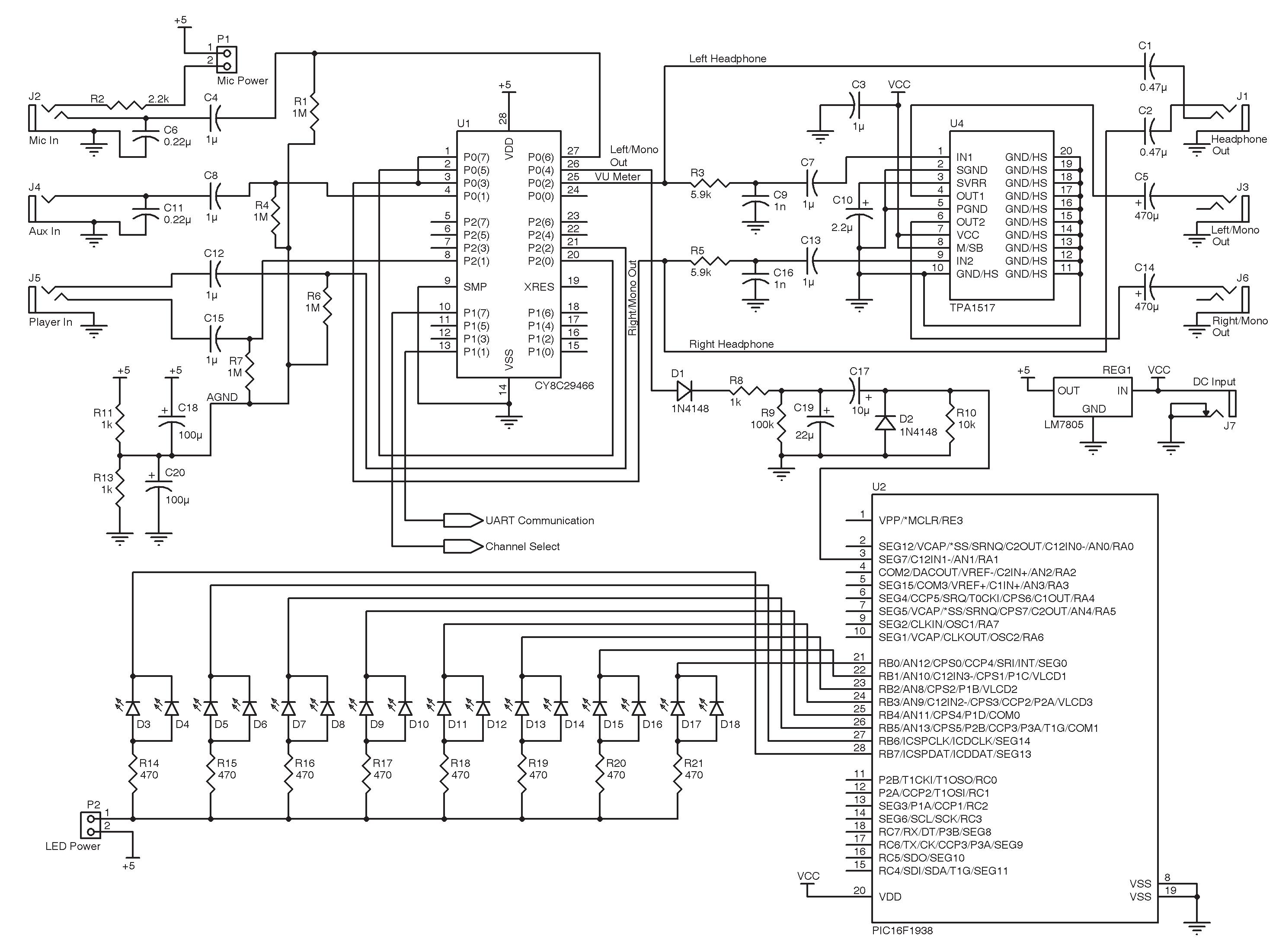
Figure 4—PodAmp schematic continued from p. 19
This meant if we used a pad with a diameter of 10 mm, a space of 0.5 mm between the pad and the ground plane should be sufficient. Because the larger the pad, the more capacitance (and therefore better touch accuracy), we made our buttons with a touchpad size of around 10 mm (give or take a couple millimeters). We figured this would be sufficient because it gave enough room for a finger to touch the pad without interfering without anything else.
Creating the slider was something we weren’t too sure about. We followed the 1/20 ratio for spacing between each pad which gave us confidence that the sensor would be robust. After looking at a few different types of sliders, we decided to use a four-channel slider and started from scratch. As for length, we used a 3” slider. This was a sufficient size for a finger to comfortably slide up and down and gave a nice feeling as far as gain-control resolution goes.
The good thing about making capacitive sliders is that any problems due to the actual slider can usually be fixed within the code. If your slider/button isn’t sensitive enough (depending on how you made it) you can increase the sensitivity within the code. You can also change what each button does when it is pressed. This gives the user many different options that are eliminated when using a fixed analog button.
PUMP UP THE VOLUME
Implementing the Class AB amplifier chip from TI was pretty straightforward. As long as you follow the datasheet, you should be up and running within a couple of minutes. The nifty thing about this chip is that it comes with a muting pin. We didn’t use it for our design, but by simply adding another capacitive button we could have easily implemented it as an extra feature for our amp.
When it comes to quality of sound, this chip was amazing. They always say “you get what you pay for,” but in this case, for the couple of bucks, we got a lot more than we bargained for. This chip can output some pretty loud and clear audio when using 4-Ω speakers. Figure 4 is the final schematic.
WHEN IT ALL COMES TOGETHER
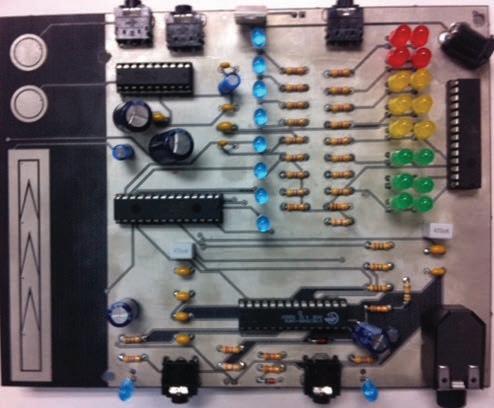
Once the PCB has been made, using a simple 5-V regulator and a 12-V/1-A (or 9-V) DC power supply, everything on the board will have sufficient power. We mounted the PCB on an angled piece of Plexiglas (like a < shape) as a stand and then
put a laminated piece of paper in between the Plexiglas and the PCB to indicate the different I/O which can be customized to each individual (see Photo 2).
Programming headers were never implemented onto this project. This was because, for our purposes, the kit comes preprogrammed. If a student wants to change or explore the firmware, they can easily pop out the microcontroller and construct their own programming headers via a breadboard. The benefit of having through-hole microcontrollers is that by using 28- and 40-pin sockets on the PCB the chips are easily accessible to students in the event of a burnt chip or otherwise.
How many personal amplifiers are out there that have capacitive sensing, digital-signal mixing, and good quality sound for only around $40? The answer is simply none. Having the ability to take new technology and implement it into your own design for a fraction of the price is an amazing skill! This project will hopefully teach students as much as it has taught us. Knowing your way around the world of electronics definitely has some great benefits, and we want to inspire young minds to explore it! I
Coleton Denninger (coletondenninger@gmail.com) and Jeremy Lichtenfeld (jeremy.lichtenfeld@gmail.com) both studied at Camosun College in Victoria, BC. They earned Electronics Engineering Technology diplomas and are planning to continue their studies at the University of Victoria. Cypress Semiconductor Corp., “AN16833: PSoC 1 –Signal Mixing with PSoC Switched Capacitor Blocks,” www.cypress.com/?rID=2925.
Microchip Technology, Inc., “AN1250: Microchip CTMU for Capacitive Touch Applications,” 2009, ww1.microchip.com/downloads/en/AppNotes/ 01250a.pdf.
Texas Instruments, Inc., “TPA1517: 6-W Stereo Audio Power Amplifier,” 2007, http://focus.ti.com/lit/ds/ symlink/tpa1517.pdf.
SOURCES
CY8C29466-24PXI PSoC and PSoC Designer integrated development environment
Cypress Semiconductor Corp. | www.cypress.com
PIC16F1939 and PIC16F1938 Microcontrollers and mTouch Capacitive-touch evaluation kit
Microchip Technology, Inc. | www.microchip.com
TPA1517NE Class-AB audio amplifier Texas Instruments, Inc. | www.ti.com

Electronics Engineering for the People
An Interview with David L. Jones
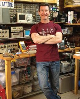
David L. Jones is a risk taker. In addition to jumping off cliffs in the name of product testing, the long-time engineer recently switched to full-time blogging. In February 2012, Dave and I discussed his passion for electronics, his product review process, and what it means to be a full-time video blogger.—Nan Price, Associate Editor
NAN: Tell us a little about where you live and work. NAN: Tell us about some of your early projects.
DAVE: I live in the Hills district of Sydney, Australia, and I was born and raised in the Sydney suburbs. I have just purchased a 50-square-meter office space to use as the new EEVblog lab, moving out of my garage lab which was a tiny 4 square meters. The funny thing is, the surface area of my new benches alone is bigger than my entire previous lab, what a luxury.
I used to shoot most of my videos in the non-air-conditioned corner of my garage, so in summertime you could actually see the sweat running down my face in the videos! DAVE: Given that it was over 30 years ago, it’s hard to recall I’m afraid. Unfortunately, I just didn’t think to use a (film) camera back then to record stuff, it just wasn’t something that you did as a kid. The family camera only came out on special occasions. So those projects have been lost in the annals of time.
My first big published magazine project was a digital storage oscilloscope (DSO) adapter for PCs, in a 1993 issue of Electronics Australia. I originally designed this in the late 1980s. (See “electronics.alternatezone.com, http://alternate zone.com/electronics/dsoa.htm.)
NAN: When did you first start working with electronics?
DAVE: The video story can be found at “EEVblog #54 –Electronics – When I was a boy...” www.youtube.com/ watch?v=XpayYlJdbJk.
I was very young, maybe six or so, when I was taking apart stuff to see how it worked, so my parents got me a 50-in-1 Tandy (RadioShack) electronics kit and that was it, I was hooked, electronics became my life. And indeed, this seems to be fairly typical of how many engineers of the era got started.
By the time I was eight, I already had my own lab and was working on my own projects. All my pocket money went into tools, parts, and magazines.
The electronics magazine industry was everything back then before the Internet and communications revolution. I would eagerly await every issue of the Australian electronics magazines like Electronics Australia, Electronics Today International (ETI), Applied and Australian Electronics Monthly (AEM), Talking Electronics, and later Silicon Chip.
NAN: You have many interests and talents. What made you choose engineering as your full-time gig?
DAVE: There was no choice, electronics has been my main hobby since I can remember, so electronics engineering was all I ever wanted to do to. I’ve branched out into a few other hobbies over the years, but electronics has always remained what I’ve wanted to do.
NAN: The Electronics Engineering Video Blog—EEVBlog—is touted as “an off-thecuff video blog for electronics engineers, hobbyists, hackers, and makers.” Tell us about EEVBlog and what inspired you to begin it.
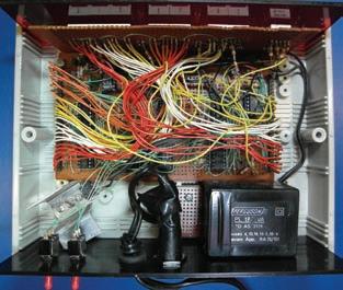
DAVE: I’ve always been into sharing my electronics, either through magazines, via my website, or on newsgroups, so I guess it’s natural that I’d end up doing One of Dave’s old projects from the something like this. 1980s. It’s a classic rat’s nest Veroboard In early 2009 I saw that (Wordpressconstruction using items from his junk bin. type) blogs were really taking off for all

Dave does ad hoc reviews of many types of multimeters
sorts of topics and some people were even doing “video blogs” on YouTube.
I wondered if there were any blogs for electronics, and after a search I found a lot of text-based blogs, but it seemed like no one was doing a video blog about electronics, like a weekly show that people could watch. Whilst some text blogs were quite good, they all had a very similar look and feel, and I didn’t see much value in having “just another text blog.” And, just like the magazines of old (and current), you don’t really get to know the person behind the blog. You just have their (usually carefully thought through and edited) words and maybe a small photo on the About page. But what are they like in real life? Are they dull and boring? Enthusiastic? Passionate? Quirky? Funny?
I had been watching some (unrelated to engineering) video blogs, and they really seemed much more exciting than text blogs, and you really did get to love (or hate!) the personality. So I thought it’d be fun to do an electronics video blog and blaze a new trail and see what happened.
Being fairly impulsive, I didn’t think about it much; I just dusted off a horrible old 320 × 240 webcam, sat down in front of my computer, and recorded 10 minutes (the YouTube limit back then) of whatever came into my head. I figured a product review, a book review, a chip review, and some industry news was a good mix. But the result was horrible, I hated it!
But not being someone who cared about embarrassing myself though, I knew enough to know that you have to start somewhere, even if you don’t like it, and it’s not what you intended. I wrote a post to the aus.electronics usenet group with a link to the video, and hit send before I could think it through twice.
To my surprise, about 50 people watched it and said they were waiting for the next episode. And they only gave positive feedback about how to improve it. So for the next episode, I moved the camera into my lab to make it look a bit more authentic, and the blog has continued onward and upward ever since.
I’ve had constant linear growth since then, and now have a regular weekly audience of over 10,000 viewers and over 4 million views on YouTube. Not to mention that it’s now my full-time job.
The “off the cuff” part came about due to my natural tendency to just impulsively rant. I couldn’t act, let alone write or read scripts on camera, so I just hit record and let it happen. And that’s the way the blog is still done to this day—hit record and talk.
I’m still amazed at how my life has changed over the last few years, all from a simple impulsive YouTube video that I thought wouldn’t get any views at all. I really did expect to go cold on the idea pretty quickly, but from all the positive comments received, I found it fun to bring out a new episode each week knowing that people were waiting for it.
NAN: Your blog’s tagline is: “No script. No fear. All opinion.” That pretty much sums it up. Tell us about your review process. Do companies send you products? Do you purchase things you might need for your own projects and then test and review them?
either owned or could get my hands on through work or wherever, but now companies are realizing the value of my blog and sending me gear for review.
So there was no pressure early on to “tone it down” and not “tell it like it is” from the start, which is my natural behavior—often to my detriment, that means I’m not really management material. So I built up a bit of a reputation for telling it like it is.
Some companies are still too scared to participate though, because of my unorthodox “tell it like it is” reviews and teardowns. Marketing people in these companies still aren’t used to the new social media approach, as they are used to magazines and websites that simply regurgitate their marketing copy, so they don’t know how to handle “bad press” when someone doesn’t like their product or something goes wrong.
But the smart companies have figured out that even if their product publicly fails (I’ve had review gear actually blow up!), then they have found they can get even more respect by publicly responding to the incident and fixing the problem. After all, engineers understand that things fail, and small things get overlooked, and it’s how a company responds that matters.
So what would previously be considered a marketing disaster—having 10,000 people watch a video of their new product blowing up—they are learning to accept the risk and stand by their product.
My review process is pretty ad hoc. I use the product on and off for a bit if possible, and then sit in front of the camera and just rattle off comments on each feature and design aspect I can find.
It’s actually pretty easy for me to get a “feel” for the product almost immediately, so most of my comments are of the “gut feel” type.
Naturally, marketing departments don’t like that approach, and often won’t agree with anything negative I say. But what’s a good review without some personal opinion?
NAN: What were, say, the top three products you reviewed?
DAVE: The Fluke 28-II multimeter is pretty memorable. Fluke gave me one and said I could do what I liked with it. Given that it was advertised as waterproof and drop proof to 3 m, I set about to test that in a fun way. So I took it through a canyon trip here in the Blue Mountains, throwing it down waterfalls, and jumping off cliffs into pools with the multimeter hanging from my harness. It survived that, so then I proceeded to abuse it some more by throwing it out of a moving car and dropping it from various heights until I finally got it to fail, well above its rated spec. An amazingly rugged meter.
It’s always fun when review products fail, and there seems to be somewhat of an EEVblog curse here, where many products I get seem to be the outliers on the manufacturing bell curve and have an issue in some way. It was hard to beat the Extech Instruments RC200 SMD Tweezer multimeter for this, with it actually blowing up in my hand as I measured the mains wall socket. It turned out there was a design oversight in the unit which, as luck would have it, I was the first to discover. But to Extech’s credit, they investigated, admitted the problem, and redesigned the product in record time.
It’s not every day you get to drop a $30,000 oscilloscope, but that’s exactly what I did with Tektronix’s new MDO4000. They originally were very hesitant to let me do a teardown of the product, as they were scared I would break their precious $30,000 scope, but at the 11th hour they finally relented. So I thought it’d be fun to give them a scare. They didn’t say I couldn’t drop it, so that’s what I did—and I had them very worried for a while about what condition they’d get it back in! (Note: No oscilloscope was actually harmed in the filming of that video, thanks to some prestidigitation.)
NAN: You mentioned in EEVblog #231 that 2011 was big year for you. You took many “gambles,” including becoming a father, switching to full-time blogging, and purchasing an office lab. As the first quarter of 2012 comes to a close, how are these changes affecting you?
DAVE: The big change is positive, in that now I have some of my life back. When I was working full time and doing the blog on the side, it was consuming most of my spare time, so to now get my weekends back has been a big improvement in family relations. Something I’m sure any midnight engineer can relate to. Little Sagan has changed things a lot, for the better, coming along just as I went full time, my best project by far! (See “EEVblog #175 - Project Sagan,” www.youtube.com/watch?v=dzrtEYmuQJQ.)
NAN: Your videos are viewed as many as 6,000 times a day. What types of responses do you get from viewers?
DAVE: Most are positive, but unfortunately anonymity on the Inter- µWatch concept design net does also bring out the worst in people, so you have to learn to ignore the negative comments, which can be quite harsh.
One thing I’ve found rather disheartening is that the high volume of comments and e-mail means I can no longer keep up with replying to everyone’s questions. And I have always enjoyed helping people out with any questions they might have—right back to the early pre-Internet magazine days when I would handwrite a reply, stick it in an envelope, and lick a stamp.
And, thanks to continuous growth, that’s now upwards of 8,000 to 10,000 views per day, thanks to YouTube being the world’s second biggest search engine.

NAN: You also mentioned that your plan for 2012 is to “settle into your lab.” Tell us a little about your lab. What types of projects are you currently working on?
DAVE: I’m working on a novel power-supply kit, in which I’m now up to Part 9 in a video design series for. I’m working on (hopefully) the world’s first canyon navigating quadcopter with a friend of mine. And building a Makerbot 3-D printer as well.
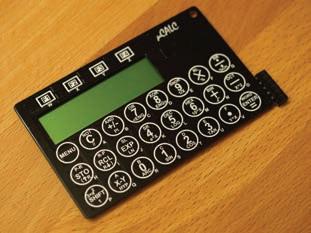
Plus, I’ve always got many abandoned projects that never saw the light of day that I occasionally resurrect and work on again, like my µWatch, the world’s first credit-card size scientific calculator watch using all off-the-shelf parts and techniques, my µCalc, which is a spin-off from the µWatch, and other small projects.
Like many design engineers I’m sure, I have a rather short attention span, so I’ve got a lot more half-finished projects than finished! (See “EEWeb Pulse,” EEWeb.com, Issue 18, 2011, http://s.eeweb.com/pulse/eeweb-pulse-2011-18.pdf.)
NAN: An interesting recent project featured on your blog is the µCurrent. Tell us more about it and how you typically come to feature projects.
DAVE: This is actually an old design I did before I started the blog, and had published in the Australian Silicon Chip magazine. Like many projects, it grew out of a personal need to accurately measure current in a project, where it just so happened that the multimeter’s burden voltage was causing a big problem.
Sure, I could have overcome that the traditional way by winding up the wick on the power supply and using several meters to compensate for the burden voltage, but that’s not very elegant.
I looked around and couldn’t find a product that would
I thought an Aussie/Yank combo with a Johnson of High-Speed Digital Design, clash of personalities might work well A Handbook of Black Magic fame was on show. But more importantly, Chris very memorable. He spoke well and seemed enthusiastic, which is the main regaled us with many industry stories. requirement for a project such as this. So I drafted an e-mail to him about my idea NAN: What was the last electronicsfor a show, but I didn’t send it because I design related product you purchased wasn’t sure if I had the time to commit and what type of project did you use to both projects. it for?
A few weeks later, again by coincidence, Chris contacted me for an inter- Dave’s in-progress µCalc project DAVE: I decided to include Arduino view he wanted to do with me. So I told compatibility in my new power supply him about the co-hosted show idea, and why not answer project (an Atmel ATmega328) so it would possibly appeal the questions on the show as a start? We both liked the to a broader range of beginners. But I initially thought that idea, and like my video blog, didn’t really think about it turned out to be a big mistake when Murphy ensured that too much. We just picked up some mics, made a Skype I struck every bug in the Atmel AVR and Arduino tools! call, and hit record. And that recording became our first show. At the time it didn’t have a name, so we just mar- NAN: Full-time blogging is a rather new endeavor for you. keted it on our respective blogs as the Dave Jones & Chris Where do you see yourself in the next five to 10 years? Gammell Show. The show was popular and we got quite a bit of feedback, and within time the show would get a DAVE: I honestly don’t know what the future will hold, name, its own website, and now a loyal following as the and that’s the great thing about it. If you told me two years world’s most popular electronics radio show. ago that I would be a full-time engineering video blogger, I would have just chuckled. Five to 10 years is too far in the NAN: Who has been your favorite or most memorable guest? future. I have a hard time trying to predict next month let alone that far ahead, so I don’t try. I just do what I enjoy, DAVE: The best shows are always when we have guests on do it my way, and see where it goes. Because if you aren’t who have many interesting stories to tell. Dr. Howard doing what you enjoy, then I don’t see the point. I


$10.00 each
(Qty 100)
The gridARM™ System on a Chip (SOC) is a high performance, low cost, low power, highly integrated single chip with 10 / 100 / 1000 Mbps Ethernet, USB, CAN, Serial, SRAM Memory, SPI, I2C, RTC and internal peripherals designed to provide a complete solution for embedded applications.
THE NETWORKING EXPERTS
800.975.4743 USA • 1 630.245.1445
gridconnect.com/gridarm.html
Leaders in the embedded and networking marketplace providing network hardware, high quality software and services

