31 minute read
Contract Manufacturing

from NE_22_11_20
by Hiba Dweib

Bouncing back
After years of offshoring, the UK’s contract electronics manufacturers are seeing strong order books. By Graham Pitcher.
Advertisement
The impression given by a range of national media is that UK manufacturing, in general, is on the ropes. But when it comes to the electronics sector, nothing could be farther from the truth; certainly in the opinion of Phil Inness, chairman of the Electronic Manufacturing Services Association (EMSA) group within trade association Intellect and managing director of Bedford based manufacturer Axis Electronics.
He believes the UK contract electronics market is probably worth £1.4billion a year. “The market is in pretty good shape,” he observed, “and is certainly growing in excess of 5% a year.” In his role as EMSA chair, he sits down on a quarterly basis with the members to see how things are going. “Most companies are positive,” he reported, “and have been for the last year. As far as we can tell, order books are as strong as they have ever been.” The one potential dark cloud on the horizon is a decline in business. “Some comments were made at our last meeting about a ‘softening’ in demand, but those companies have been unable to quantify their feeling.”
The performance of the UK’s contract manufacturing sector is encouraging, given the degree of offshoring which has taken place over the last decade. “There has been a mass migration of work offshore in the last 10 years,” Inness noted. “Some of this should have gone overseas without question,” he accepted, “while some should not have, but did. Companies now realise that offshoring isn’t going to be a fix for all evils and there is much cleverer decision changes, they have to keep up and the industry, as a whole, is much closer to the leading edge than it has been and more capable of responding to customers’ needs.”
With the technology in place, Inness believes that EMS companies don’t necessarily have to sell. “It’s all about giving the customer what they need so they can sell their products on the global
making today.”
The challenge of offshoring has seen the UK EMS sector improving its efficiency in the last five years, Inness believes. “There are now a lot of good UK companies that can do a good job at a good price,” he asserted. “When you compare that to the risks involved in offshoring, it makes sense to keep the work here in the UK.”
Inness reflected that many companies jumped on the offshoring bandwagon without giving the move enough thought. “They may have realised certain savings, but then ended up with obsolete stock or found the work was wrong and had to be put right, with all the time delays involved. Now, there’s smarter procurement; if someone wants 73 units, they can order 73 units from a UK company and have no wastage. If you go offshore, you may have to order 100 units or more to get the price breaks.”
He sees three distinct bands of EMS business. “At one extreme, there’s high volume consumer. At the other, low volume, high reliability. And in the middle is a large amount of business up for grabs.”
Vying for this business are some 250 companies, broadly grouped into four bands. “There are the multinational names,” Inness said, “then 10 companies or so turning over roughly £50million a year. Below them is a group of probably 50 or 60 companies doing between £5m and £20m a year, then the rest.”
In general, said Inness, the UK’s EMS sector is recruiting and investing. “Companies continue to invest in new production equipment. As technology
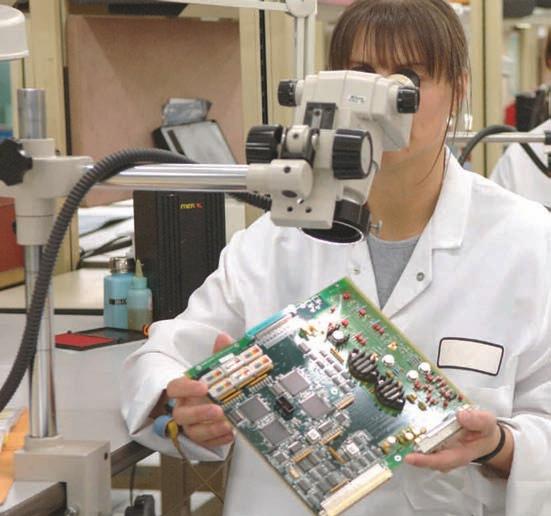
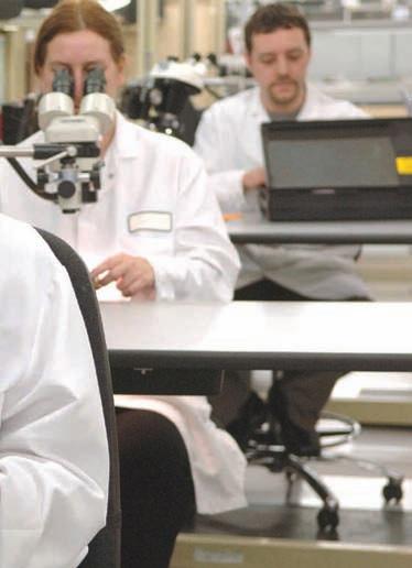
Top: EMS companies need to provide products to specification, on time and at a competitive price
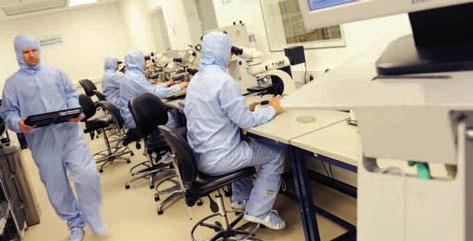
Above: Axis has a Class 10,000 cleanroom, supporting bare die attach, wire bonding and integration for rf products
market. They want top quality products made as quickly as possible at a competitive price.”
With new markets opening up, Inness believes it’s a good time for the UK EMS sector. “Renewable energy is bringing opportunities, as is wireless technology. I’m also hearing good stories about medical, but I have yet to see anything of substance.” Underpinning everything,
however, is the traditional strength of the aerospace and defence sector. He described business here as revolving around ‘a basket of products, some of which have been around for ages’. “But there is leading edge business emerging and a lot of embedded computing.” Even so, he believes companies still need to be ‘clever’. “There’s a range of requirements which need to be met in order to get business from new customers.”
One item on the agenda at the next meeting of EMSA may well be trying to improve the sector’s visibility within Intellect. Although one of Intellect’s groups, EMSA is not always immediately obvious to Intellect members. “Intellect has a large membership,” Inness pointed out, “and we want to get more benefit from those companies.” He also noted that, during the last six months, EMSA has been working more closely with Intellect’s PCB Manufacturing Group.
As far as Axis Electronics is concerned, business is good. “We grew revenues by 50% in our last financial year and are 20% ahead of the same time last year,” Inness said. “There’s a strong order book across all sectors and what’s driving this is customers we got involved with a couple of years ago placing business.”
Headcount is also growing. “We are now around 160 people,” he continued, “which is almost double that of 18 months ago.” Yet Inness admits that getting the top quality people needed to run the business remains a challenge.
Here, he suggests the Government could do more to help by providing tax credits against training costs. “People are losing their jobs in the public sector and we’re struggling to get skilled employees. Let’s get some support to help us retrain them.”
Business is also growing through making better use of existing equipment, including additional manufacturing shifts. “But we’re also boosting our security classification and the additional services we offer – such as microelectronics design, conformal coating, environmental screening and product repair – are making meaningful contributions.” Axis is also ‘pushing hard’ on the SC21 defence supply chain initiative.
But, like small businesses around the country, Axis faces the challenge of making changes and growing at the same time. “Trying to overlay business improvement is challenging,” Inness admitted.
Inness’ recipe for contract manufacturing success is to invest in technology and people and to have the right processes. “You have to look after all three,” he contended. He acknowledges this involves climbing a learning curve. “Successful companies are following the principles,” he noted, “while some aren’t, but will get there.” His worry is that some companies will not. “They will go ‘pop’,” he believes, “but there won’t be too many of them.”
Neither has Axis had problems in getting access to the money it needs to expand. “Few members of EMSA have complained about the lack of access to funds. Banks have the money,” Inness believed, “and it’s a great time for EMS companies to invest.”
Now, having broadly put its house in order, it seems UK companies are beginning to win high volume manufacturing contracts that, only recently, would have been placed in the Far East without second thought. How times change. www.axis-electronics.com www.intellectuk.com

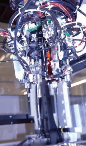
Investing in the latest technology is critical for EMS success


Making the link
Plugging things into computers used to be something of a lottery; the chances were that things simply wouldn’t work; maybe an obscure setting had not made correctly. And even if the peripheral could be ‘seen’ by the host PC, that didn’t always mean it would work in the way you expected.
Over the years, the computer industry has been good at overcoming issues like this and the solution that has dominated the market since the late 1990s is the Universal Serial Bus, or USB. With a bit of help from the operating system, USB brought plug and play to the PC and to a wide range of peripherals.
Where, in the old days, one peripheral occupied one port, USB enabled daisychaining – in theory, you could attach 127 devices to one port – and the emergence of the USB stick, the portable memory device without which, it seems, we cannot survive.
USB wasn’t, however, the ‘slam dunk’ that it appears. Competition came from Firewire, which could support up to 400Mbit/s at a time when USB only offered up to 12Mbit/s. USB won through when version 2.0 was launched, despite the fact that Apple was a major Firewire supporter. In the end, Apple climbed on the USB bandwagon in 2003.
Now, the unrelenting thirst for bandwidth is pushing the development of USB version 3.0, but the gestation period has been long; work started in the mid 2000s and it is only now that USB 3.0 enabled devices are appearing. But the wait should be worthwhile; USB3.0 brings data transfer rates of up to 5Gbit/s.
Even so, there’s always an opportunity for Apple to ‘go its own way’ and it has recently – in association with Intel – brought out Thunderbolt, said to be capable of handling 20Gbit/s, with a 100Gbit/s version on the drawing board. Whether Thunderbolt will make a dent on USB’s dominance of the PC world remains to be seen, but Apple’s interest in any market holds the potential of moulds being broken.
Graham Pitcher, Editor, New Electronics Have you thought how difficult life would be without USB connection? This common interface specification allows plug and play connectivity at data rates approaching 240Mbit/s.
While the industry is readying itself for USB3.0 and even faster data rates, another contender has appeared. Digi-Key is pleased to partner with New Electronics to look at the future for serial communications.

Mark Larson, President, Digi-Key
As an extension of its commitment to providing top quality product, Digi-Key is pleased to partner with New Electronics to provide relevant, useful information to UK engineers.
Long-running serial
When you consider how difficult it was to hook up peripherals to a PC in the late 1980s and early 1990s, it is little wonder that the Universal Serial Bus (USB) should have been such a success. Users had to wrestle with arcane interrupt and address selections to attach more than a couple of serial or parallel peripherals to a computer, often with unpredictable results and rarely entirely successfully.
Realising that, with the move to Windows, things wouldn’t get better if PCs were stuck with RS232 serial and IEEE1284 parallel ports, seven companies clubbed together to try to improve I/O. When the first USB silicon appeared a year later, it promised a much easier life for PC users, although it took several more years for the interface to be adopted widely.
One problem was that, although USB was supposed to support more than 100 peripherals connected to a single host port through a tree of intermediates, in practice, this did not turn out so well. It took an update to version 1.1 for the specification to be robust enough to handle hubs. It was only after version 1.1 appeared that USB ports came into widespread use, roughly coinciding with the release of Windows 98.
In USBv1, peripherals could support either Low Speed, with a 1.5Mbit/s transfer rate, or a 12Mbit/s rate with the highly confusing name: Full Speed. Consumers naturally assumed that Full Speed-capable USB 2.0 hubs and devices would support the later revision’s higher maximum data rate when, in fact, they would only run at up to 12Mbit/s.
Over time, USB has competed more strongly with the IEEE1394 Firewire interface championed by Apple, which the introduction of USB 2.0. Partly because it was intended to be used for hard drives, Firewire has a comparatively complex command set and has built-in support for direct memory access (DMA) transfers. USB, by contrast, generally used programmed I/O to send and retrieve words from the interface, although the adoption of the Open Host Controller Interface (OHCI) did allow the controller to offload some transfer functions from the host processor.
The second major version of USB appeared in 2000 – offering a top claimed datarate of 480Mbit/s. To distinguish High-Speed peripherals from the existing Low-Speed and slightly ironically named Full-Speed devices, the USB Implementer’s Forum developed a ‘chirping’ protocol that the newer devices could recognise but which would not confuse older interface controllers. Once set, the host would treat the device as a High-Speed slave until the next reset.
USB 2.0 was made a firm standard in 2001, quickly turning into a mainstream offering on PCs and peripherals. Even Apple, which held out against offering USB 2.0 ports on its machines – largely

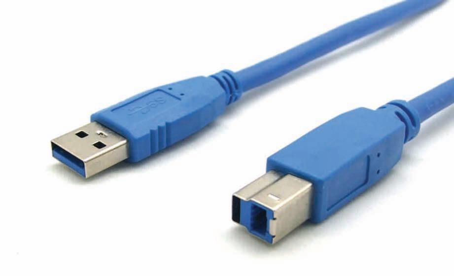
USB 3.0 cables have nine wires instead of the previous four. The cables also feature modified connectors. spent close to a decade in development before appearing as standard on Macs. Apple wound up adopting USB – putting ports on its machines before the 1.1 revision was complete – ahead of its favoured I/O standard. At the time, the two interfaces occupied different parts of the market.
Firewire was designed to daisychain a comparatively low number of peripherals, instead of attaching them through hubs. The big difference was the peak datarate. The low-voltage differential swing (LVDS) interface represented, at the time, a marked change in the way that I/O worked electrically. The reduction in voltage swing, to just 350mW in each wire, reduced electromagnetic interface dramatically and allowed comparatively high datarates. At introduction, Firewire could pass up to 400Mbit/s, allowing it to be used as a replacement for the SCSI bus – Apple’s original intended application for the I/O standard.
Another key difference from USB is the amount of host intervention needed – something that helped Firewire maintain a small, but significant, grip on audio and video peripherals even after
USB3_RX
USB3_TX GND
D–D+ VBUS
GND

Chris Edwards explores the world of serial communications between PCs and peripherals
Fig 1: How mixed USB systems communicate
CPU
Host controller
HS USB host controller SS DRAM
FS hub SS HS SS HS
LS FS
SuperSpeed Links
High-Speed Links
Full-Speed Links
Low-Speed Links
because it already had high-speed peripheral support through FireWire –started to support it from 2003.
The dramatic success of USB 2.0 is, in some ways, a problem for its successors. There is not such a huge pent-up demand for a new interface as there was for USB 2.0. However, there are applications such as high-end audio and video storage and capture systems that can make use of additional bandwidth, not least because real-world datarates on USB 2.0 tend to top out at around 240Mbit/s.
USB 3.0 has taken a while to get to where it is now. Development work started in the mid-2000s, with an initial specification appearing in 2008. Even now, it is only just beginning to appear on PCs and high-speed peripherals. The interface is not expected to make it into Intel’s motherboard chipsets until Panther Point arrives in 2012.
USB 3.0 does make extensive changes to the protocol, but maintains separate signal lines for USB 2.0 and 1.1 compatible devices. It even needs a slightly silly name to distinguish its protocol from the High Speed and Full Speed modes of its predecessors: SuperSpeed.
To improve bandwidth, USB 3.0 adopts much of the physical layer from PCIExpress 2.0, such as the 8B/10B encoding system and data scrambling to reduce electromagnetic interference. The scrambling technique prevents repetitive bit patterns, such as 10101010, from generating strong frequency peaks. A further change is that connections are no longer half-duplex: there are separate data lines for transmit and receive, which should make better use of the maximum available data rate of 5Gbit/s than USB 2.0 can make of its nominal 480Mbit/s.
More advanced forms of LVDS signalling have made it possible to transmit at several gigabits per second over a differential pair through the use of pre-emphasis and active equalisation. But the SuperSpeed protocol is very sensitive to cable length such that the distance from the USB controller in a host chipset to the connector at the edge of the PCB is now a major source of performance loss. For this reason, some of the electrical conditioning is moving out of the chipset and closer to the cable. Manufacturers are now selling redrivers that provide a boost for weakened signal just before it crosses from the connector to the cable.
A further change is that packets are no longer broadcast across a tree of devices (see fig 1). Hubs will route packets directly to the target device so that other devices in the tree are not forced to wake from sleep to check on a packet any time something appears on the bus, as with USB 2.0.
The data-transfer protocol is more streamlined for SuperSpeed, partly thanks to the adoption of the full simplex model (see fig 2). In previous forms of USB, data transfer involved a multistage
SS HS
SS
LS SS
HS hub
HS LS
FS
In USB 3.0, hubs will route packets directly to the target device so that other devices in the tree are not forced to wake from sleep
handshake. First, the host would send an IN-token packet to initiate the transfer. Once the slave had responded, the host would send an ACK packet and, in the case of high-speed transfers, would probably immediately follow that with another IN-token. In SuperSpeed, ACK packets have multiple functions. Instead of sending an IN-token, a SuperSpeed host will kick off a transfer using one form of ACK. Once it has received the payload, it will send another ACK that contains a command for the next chunk of data and keep doing so until it sends a final ACK that does not request additional data. There is a similar change for outgoing packets that helps to reduce protocol overhead on the bus.
Higher-speed peripherals can take advantage of data bursting in which the host asks for a number of data packets to be sent in sequence. The host can request as many as 16, sending a subsequent ACK only when all of those packets have been received.
One of the key changes in USB 3.0 is to reduce the number of times a host polls peripherals to see if they have data to send or are still operating on the bus and have not been disconnected (fig 2). Because of the master-slave organisation of USB, a peripheral can only send data when polled by the host with an IN-token. As the host has no idea when data might arrive, it simply polls on a regular basis at a frequency set by the operating system. Windows usually defaults to 125Hz for mice.
If the mouse receives an IN-token and it has not detected any movement since the last one, it will send a NAK packet, telling the host nothing has happened. The host will simply wait for another 8ms before sending another IN-token to see if anything has changed in the meantime. The SuperSpeed mechanism handles the situation somewhat better. For example, if the peripheral is a disk drive responding to a read
command from the operating system, it will have to wait for the head to reach the correct tracks and for data to start streaming back.
If the host sends an ACK request immediately after issuing the read command, the data will not be ready. Under SuperSpeed, the drive will send a NRDY packet saying, in effect, it has nothing to send yet. However, instead of being forced to wait until the next time the host asks for data, the peripheral can, without prompting, send an ERDY packet. The host will then respond immediately by transmitting a new ACK request and the peripheral will start sending the data. Because it reduces the amount of polling needed, the new mechanism improves link-power management dramatically for peripherals with bursty, intermittent behaviour.
Although USB 3.0 increases the amount of power that a hub can deliver to a peripheral – 900mA, instead of 500mA – it also has features to prevent power consumption from spiralling out of control and to deal better with peripherals that need to sleep to save power.
To maintain synchronisation, SuperSpeed devices have to transmit
The USB 3.0 type A connector, left, and the type B connector, right. Type B parts feature modified USB 2.0 type B connectors, with SuperSpeed pins added on top. All USB 3.0 connectors are coloured blue to aid identification packets constantly. This is because the equalisation system uses electrical training sequences to ensure the receiver can detect bit transitions properly and these are maintained through idle sequences once a link is established. Unfortunately, this translates into a big source of energy consumption. To overcome this, if a peripheral does not need to send data for a while, it can tell the host it is moving into a low-power mode and will retrain the link when it becomes active again.
There are three power-down modes in USB 3.0. U1 is a fast-recovery state, where the node can reduce the frequency of keep-alive transmissions but return to normal transmission within microseconds. U2 offers a bigger power saving, but a slower recovery – this time measured in milliseconds. U3 is suspend mode, which extends recovery time further, but is still of the order of milliseconds. It can only be entered into under software control, whereas U1 and U2 can be implemented using hardware timers.
The transition to USB 3.0 has provided
Earlier in 2011, Apple launched MacBook Pro computers sporting an interface called Thunderbolt. Developed primarily by Intel, the plan for Thunderbolt had been to use optical signalling to increase bandwidth to, ultimately, 100Gbit/s
Fig 2: Comparing back to back IN transactions
Host controller
6
4
ACK
IN token DATA
5
3
1
ACK
IN token DATA 2
High speed
5
3
1
Host controller
ACK header
ACK header
ACK header DATA Hdr+ payload
4
DATA Hdr+ payload 2
Super speed
another opportunity for Apple to go its own way. Earlier in 2011, the company launched a series of MacBook Pro computers sporting an interface called Thunderbolt. Developed primarily by Intel under the name Light Peak, the original plan for Thunderbolt had been to use optical signalling to increase bandwidth to, ultimately, 100Gbit/s. But the light went out on Light Peak when Intel claimed it could hit the initial target datarate of 10Gbit/s using more advanced signalling over differential copper pairs.
The cabling requirements for Thunderbolt, although not yet publicly disclosed, are even more stringent than for SuperSpeed USB as a consequence of the higher datarate. Signal conditioning now goes inside the cable itself – just behind each connector – so it can be calibrated for the correct electrical performance at the factory. Manufacturers such as Gennum are offering signal conditioners that will fit onto a tiny PCB that can be attached to the connector.
Like FireWire – and in contrast to USB – Thunderbolt is a peer-to-peer technology. There is no master at the top of the tree that is needed to initiate transfers. This decision for USB demanded a key change to the protocol to allow peripherals, such as cameras or phones, to sometimes act as masters so that they could transfer pictures to an external storage device without calling for intervention from a host PC. The OnThe-Go (OTG) variant of the USB standard allows peripherals to turn into masters when necessary.
The situation for role reversal on USB 2.0 is slightly more complex than it at first seems, due to the way the roles are reversed at the electrical signalling level and not just through an additional logical protocol.
The peer-to-peer nature of FireWire enables, for example, the target disk mode supported by Macintosh computers. Using Firewire, one computer can access another’s disk drives over the bus, with the remote machine effectively taking control of the other without direct intervention from the target machine’s OS. However, the DMA support and peerto-peer nature of FireWire and Thunderbolt threaten to open a security hole in computers. Using DMA, it is possible for a remote machine to access any physical area of memory in the target machine that is reachable by its FireWire DMA controller. A proof of concept attack was demonstrated in 2006.
In principle, a hacker could walk up to unprotected machine, attach a FireWire peripheral and minutes later walk away with sensitive data found on the target computer. The target machine might expect DMA transfers from FireWire to be made to known I/O buffers. But, as normally implemented, the DMA controller does not limit access to only those areas. They could be parts of the machine dedicated to kernel operations.
In practice, OSs such as OS X lock access to FireWire DMA if a password has been set and protection activated by the screensaver. It is currently unclear whether protective steps have been taken for Thunderbolt or how vulnerable it is to attack.
A bigger concern for Apple and Intel is whether the additional promised bandwidth will convince peripheral makers to support Thunderbolt or stick with USB 3.0 which, despite its slow start, is likely to dominate the PC industry within the next five years.
One of the key changes in USB 3.0 is to reduce the number of times a host polls peripherals
Power to the people
The fuel cell is one of those technologies that never quite makes it to the mainstream. Yet it is almost as old as the battery that many want it to replace. Sir William Grove, who devised the first one in 1839, called it a ‘gas voltaic battery’. Knowing that it was possible to split water molecules into oxygen and hydrogen by passing an electric current through the liquid, he found it was possible to reverse the process: combine oxygen and hydrogen to produce water and electricity. It took 50 years for the term ‘fuel cell’ to appear, when Ludwig Mond and Charles Langer worked on developing a commercially viable version.
NASA has used fuel cells for decades. But the alkaline fuel cells employed in the space programme had one clear design objective: to provide high energy density. The water they produced was also handy side benefit: it could be drunk by the astronauts. Operating cost, however, was not an primary concern.
Devised by British engineer Francis Thomas Bacon and subsequently named after him, the alkaline fuel cell (see fig 1) uses a solution of potassium hydroxide in water and stored in a porous solid matrix. Oxygen and hydrogen are pumped in as a charge is applied. Hydrogen introduced at the anode decomposes into protons and electrons. The electrons pass through an electrical connection to the load; the positive ions combine with negatively charged hydroxyl ions that pass through the electrolyte solution to produce water that is then pumped out of the system.
Unfortunately, CO2 and even water itself poison the process, so the cell has to be sealed from the atmosphere. Because the unit has to be sealed, NASA
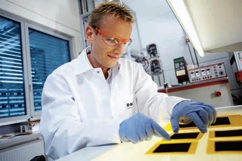
A BASF researcher working on catalytic exchange membrane materials for proton exchange fuel cells could get away with using asbestos as the matrix for the electrolyte chemical. The catalysts needed for the cell can also be pretty cheap, using metals such as nickel. The Apollo programme employed platinum for its higher efficiency.
Overall, the cell is very efficient: only around 30% of the energy it generates is lost. But the cost of sealing and maintaining the purity of the chemicals needed makes the alkaline design an
Fig 1: An alkaline fuel cell
Electron flow unlikely candidate for the fuel cell of the future.
One way around the problem of alkaline fuel cells is to change the electrolyte. The approach that the US Department of Energy reckons will work best for future vehicles is the polymerbased proton-exchange membrane. Instead of using a porous ceramic soaked in electrolyte, this uses a thin plastic membrane not unlike clingfilm in overall look and feel, although it is normally a fluoropolymer like Teflon rather than polyethylene. The idea is to allow protons to pass through the membrane, but to block electrons so electron transfer occurs only by completing an electrical circuit from anode to cathode.
Fluoropolymers are good electrical insulators, but can be turned into ionic conductors. For example, DuPont’s Nafion puts sulphonic acid groups onto a Teflon polymer backbone. Protons on the acidic nodes can hop from one to the
Load
Hydrogen
Water Hydroxyl ions
Anode Electrolyte Cathode Oxygen
Despite holding great promise, Chris Edwards finds the fuel cell has yet to breakthrough.
Fig 2: The proton exchange membrane fuel cell
6e–Load
6e–
CO2 Water, unused methanol/water
Fuel methanol/ water CO2 + 6H
H2O + CH3OH
Anode (–electrode) H+
H+
H+
H+
H+
H+ H+
H+
H+
H+
H+
H+
Proton exchange membrane 3H2O
6H+ + 3/2 02
Cathode (+electrode) Water, unused air
Oxidant air (oxygen)
other and, in an electric field, will tend to move one way through the membrane towards the cathode.
The fuel cell can work at relatively low temperatures compared with other designs: 100°C is normal for a protonexchange membrane design. Because the electrolyte can be reduced to a thin membrane, the cell is relatively compact and easy to scale up for large power densities. It also starts up quite quickly and is not poisoned by gases such as carbon monoxide. These factors make the proton-exchange membrane cell (see fig 2) the most likely option for hydrogen powered vehicles, even though the 50% operating efficiency for today’s designs is much lower than the Bacon cell’s.
The big problem with the protonexchange cell is its reliance on hydrogen. As a component of water, hydrogen is hardly scarce, but it takes a lot of energy to obtain molecular hydrogen and then transport and store it. Research is under way to find more economic ways to liberate hydrogen from water. One possibility is biotechnology.
Schemes such as the EU-funded BioModularH2 project have been formed to develop organisms that feed on sunlight to power the production of hydrogen from water or feedstock chemicals such as acetates. Bacteria that crack water in hydrogen and oxygen exist – many are nitrogen-fixing species already useful in agriculture that produce hydrogen as a part of the process. However, they produce relatively little gas compared with the amount of energy and food they consume, so scientists are trying to redesign the enzymes they use to make them more efficient: the best naturally occurring hydrogen producing enzymes are, unfortunately, poisoned by oxygen.
Some researchers are trying to tweak the enzymes to make them less sensitive to oxygen; so far with limited success. Another approach is to stick with the natural enzyme and increase production by engineering proteins that are efficient at removing oxygen before it can do any harm. These hydrogen producers are longer-term options: noone is looking at a time-scale shorter than ten years before even pilot production.
Even if hydrogen becomes easy to produce, it remains a poor choice for portable applications which are saddled with slow-to-evolve battery technology. However, mildly acidic organic liquids, such as ethanol and methanol, make good substitutes for molecular hydrogen as they will donate protons for these reactions. The direct ethanol fuel cell can even use the same type of protonexchange membrane as the hydrogen version. One big advantage of using ethanol is that a biomass industry has been established. The ethanol group remains on the anode side to be oxidised into carbon dioxide, donating protons that can cross over to the cathode as part of the process.
The most promising candidate for portable devices remains the direct methanol fuel cell. Here, methanol is dissolved in water, with the recombination of ions taking place at the cathode. However, this is the cell’s main drawback – because methanol has to cross from anode to cathode, the reaction is much slower and even less efficient than the proton-exchange cells. Today’s designs also tend to produce less than 0.5V.
Fuel cells suffer from polarisation which means that as current density increases the voltage tends to drop. Close to peak current, the voltage can drop off dramatically because of losses from the
The proton-exchange membrane cell is the most likely option for hydrogen powered vehicles
Fig 3: A generic fuel cell
Fuel in
Depleted oxidant and product gases out Load
2e–
H2
Positive ions 0.5O2
H2O
Anode Negative ions
Electrolyte membrane H2O
Cathode Oxidant in
Depleted oxidant and product gases out
effects of transporting a high concentration of fuel across the electrolyte – it starts to take a long while to refresh the chemical at the interface and remove the waste products. As a result, cells need to be stacked to develop a usable voltage. In portable systems, this is likely to be achieved through a large number of cells constructed using microfluidic techniques to prevent the size of the cell from spiralling out of control.
Although methanol is both toxic and flammable, the International Civil Aviation Organisation’s dangerous goods panel voted in late 2005 to let passengers carry micro fuel cells and fuel cartridges onto airplanes. The US Department of Transportation decided in 2008 to allow up methanol cartridges, of an approved design, to carry up to 200ml in liquid –twice that of the current volume allowed for cosmetics in carry-on baggage. However, the problem for methanol fuel cells remains less one of fear of an airline ban, more their real-world performance.
Fuel-cell construction is trickier than with proton-exchange designs because it needs to use water to dilute the methanol and encourage the protons and the methanoate groups to disassociate. As water adds to the weight, it makes more sense to recycle the liquid, rather than to supply it fresh. That adds complexity to the design. Also carbon dioxide needs to be removed efficiently from the solution that passes out of the fuel cell.
Although the aim is ultimately to power laptops and phones, the main target for methanol fuel cells currently lies in military applications: replacing bulky batteries for backpack radios and other battlefield electronics.
If the fuel cell does not need to go anywhere, the options expand considerably. Stationary, grid-based cells might provide short-term generating capacity to cope with peaks in demand or for reversible systems as alternatives for batteries in power networks that have a large proportion of generation based on
Military applications remain the most immediate target for methanol based fuel cells, replacing bulky batteries for battlefield electronics renewables. As they can be fixed in place and shielded, they can use more extreme fuels and processes.
For example, the protonic ceramic fuel cell needs to operate at more than 700°C in order to oxidise gas-phase molecules electrochemically. These ions can pass through a porous, solid electrolyte without demanding the use of a liquid that might leak out over time and contaminate the ground. However, this design has a low current density, although this can be increased with a thicker electrolyte layer. As it can support an efficiency of up to 65% using pipeline-borne natural gas, this is one looks to be a good candidate for gridbased cells.
Another technology suited to use in stationary cells is the phosphoric-acid fuel cell. While this operates at 200°C and uses the corrosive acid as an electrode, pilot plants have been built and are being tested at a number of sites.
Although large cells such as these work at high temperatures, some researchers have pursued the option of using the solid-oxide design in portable products. The Fraunhofer Institute has developed one that uses methane as its fuel source, although it is aimed primarily at military systems that need 100W. However, the Massachusetts Institute of Technology has developed one using that uses infrared light, generated by incandescent gas as an intermediate form of energy, although efficiency was just 5%.
Even though parts of the industry seem to have settled on mainstream architectures, such as proton-exchange or direct methanol, more than 170 years since its invention, the options for the fuel cell are still pretty open.


