6 minute read
FORE WORD


My interest in digital fabrication stems from my love for art, topics of identity, activism and architecture. Where these four intersect, is how I understand digital fabrication with the help of my favorite book: Race and Technology by Ruha Benjamin. As a Sudanese woman, it is empowering to know how much agency we actually have when it comes to design and the intentionality behind it, when we are learning by immersing ourselves in this field. I am constantly trying to push my understanding of how I work with art, digital fabrication and architecture and how that directly relates to artivism. This summer, I had the privelege of working with the OPN Innovation Team and find ways to 3D print through Revit and Rhino Inside Revit. 3D Models have existed as a form of communicating an idea or concept. With the use of innovative practices of digital fabrication, we can now build models much faster than before. The value in 3D models is in their ability to spark conversations because they become immediately more accessible across various levels of knowledge. To be able to hold a drawing in your hand to understand a building is remarkable. What is even better is that this journal of successes and failures can show you that anyone is capable of doing this!
Programs Used: plate is clear
Advertisement
1B Ensure that the filament (add kinds of filament from Design Hour) is associated with the correct print core (the extruder that is compatible with printing the material)
1C Proceed to Step 2A
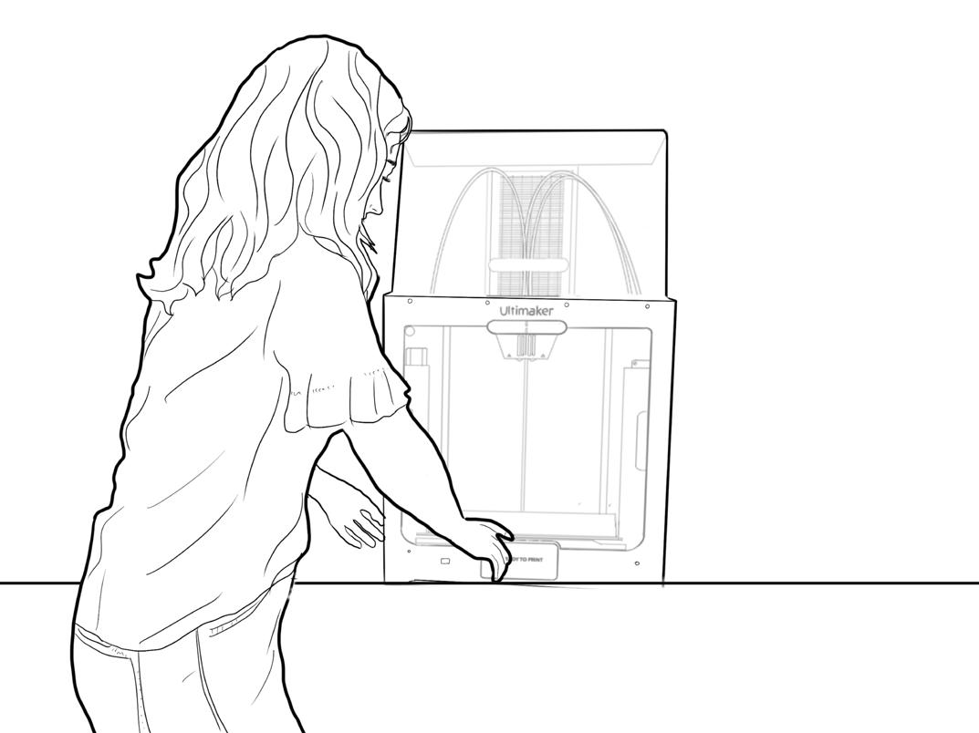
2A Loading the filament is a simple process by selecting the machine icon (icon) and following the steps on the screen.
2B After ensuring that the material is fully loaded and has extruded properly, send your file to print over the cloud on the CURA software
2C Prep the build plate by gluing the base with the avail able glue sticks! Purple is cool!
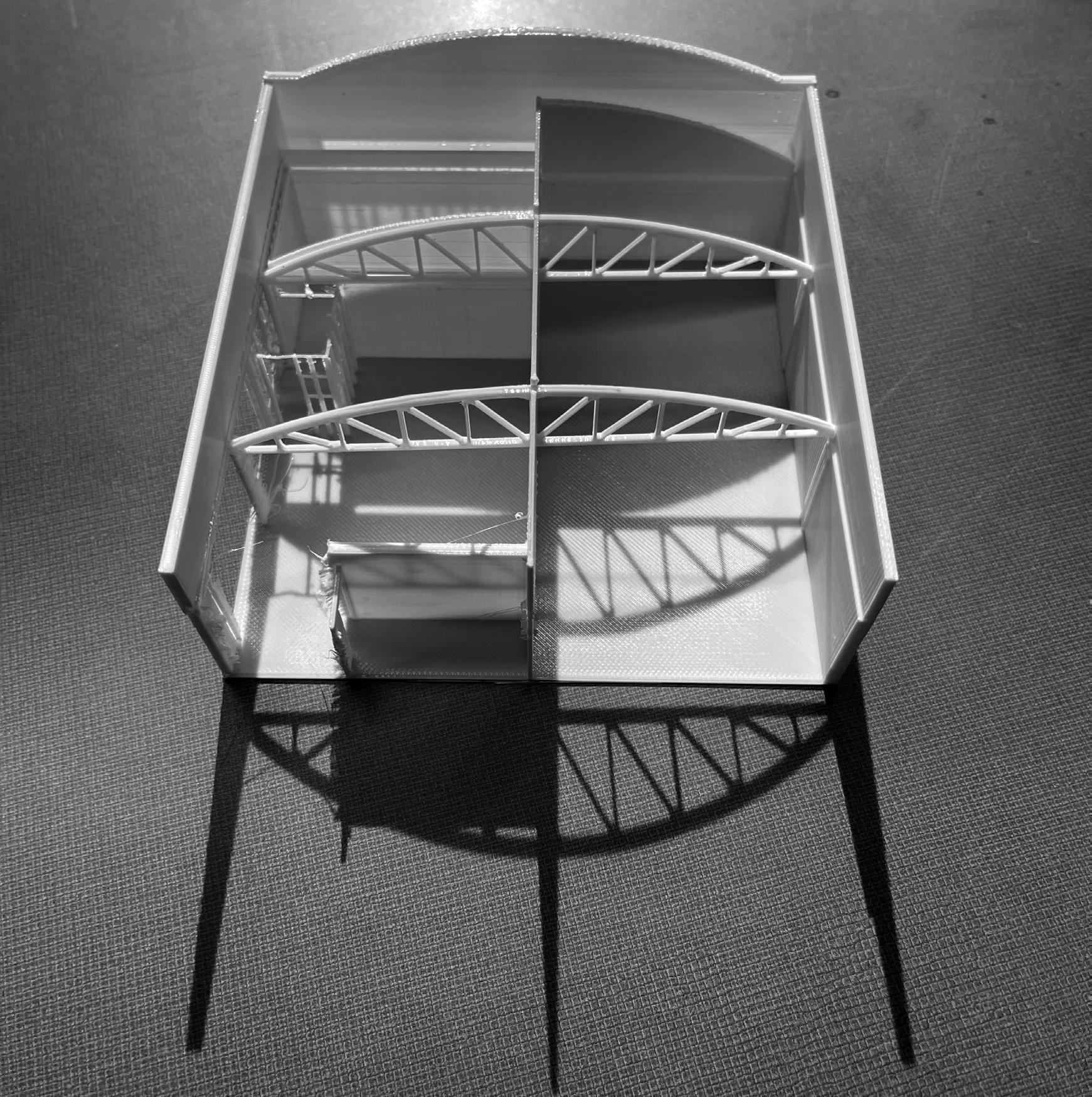
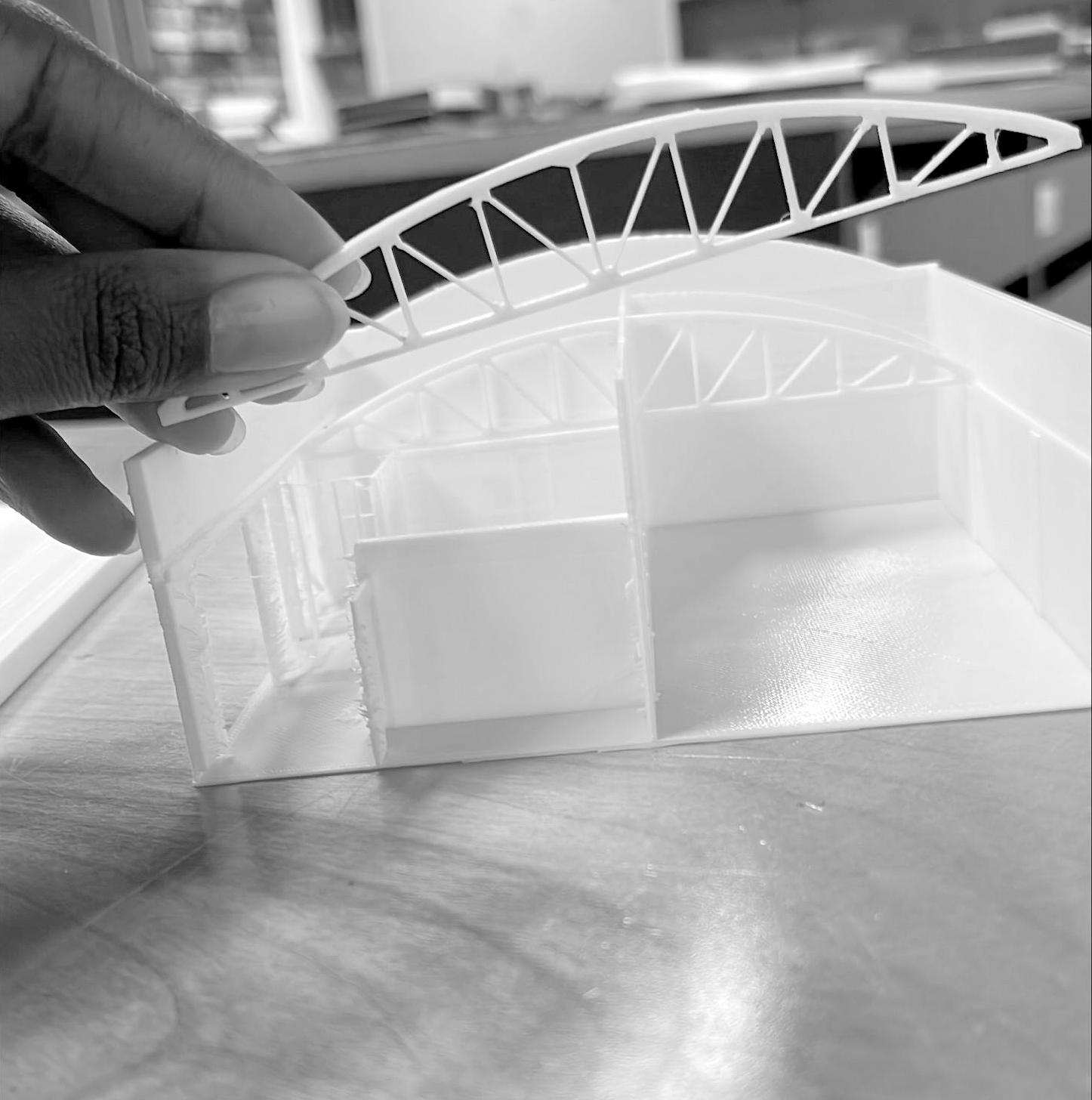
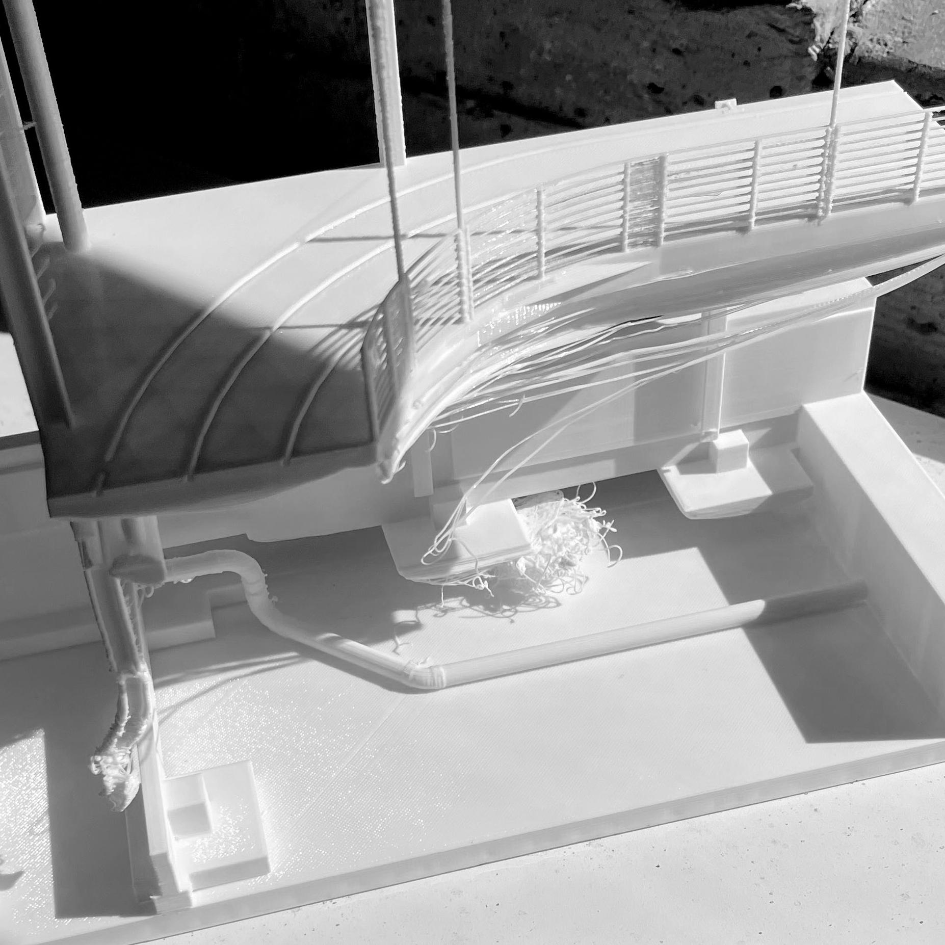
Multipart Section Model
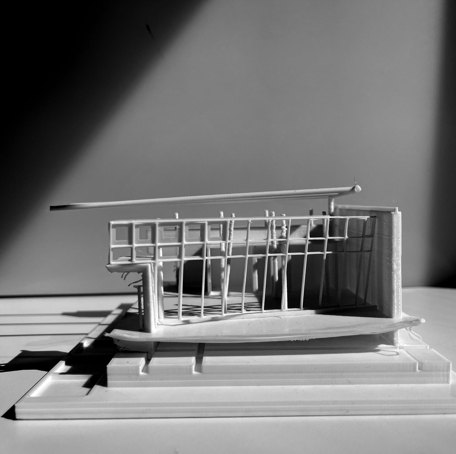
PREP TIME 5 HR
PRINT TIME 16HR
Clean Up 8hr Soak In Soap
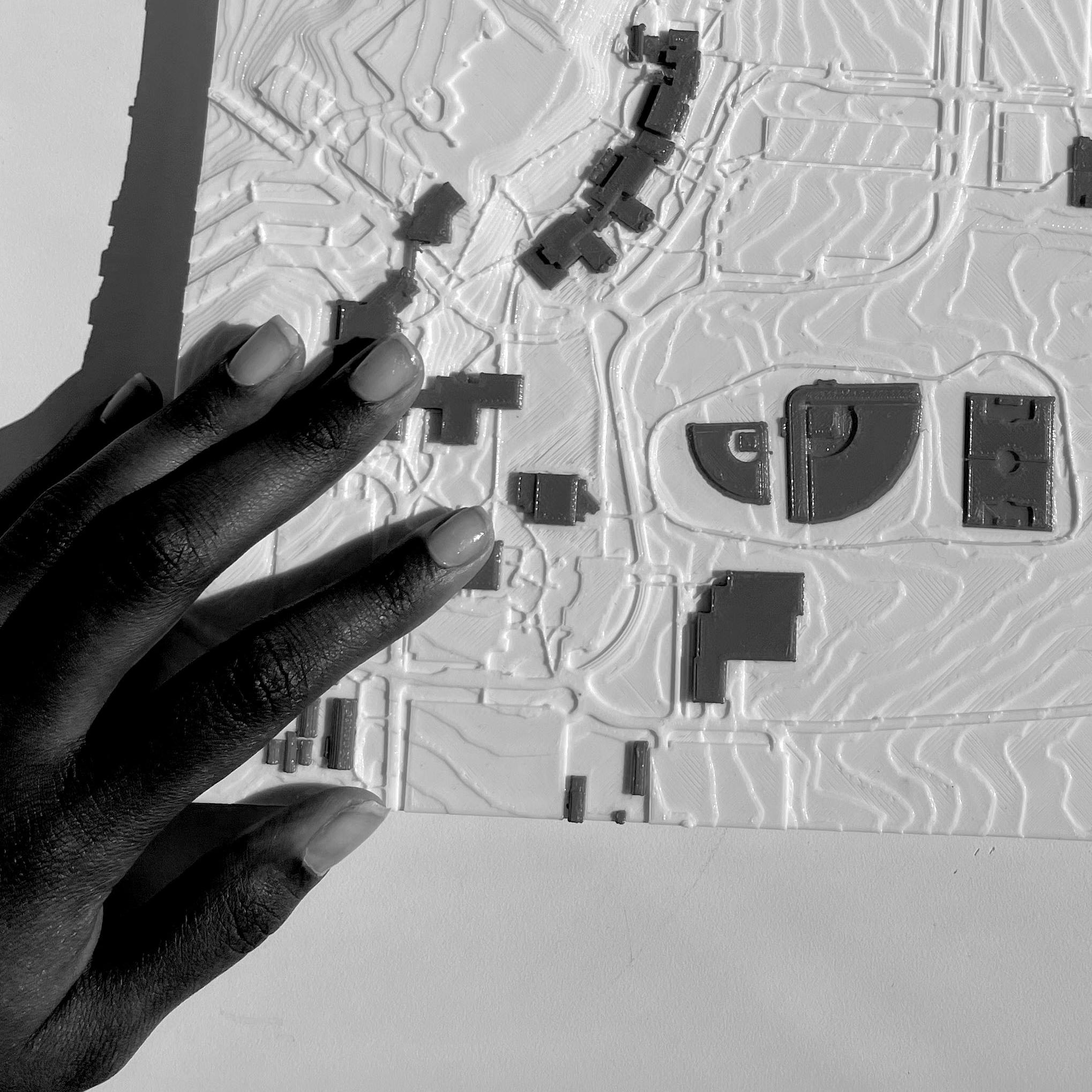
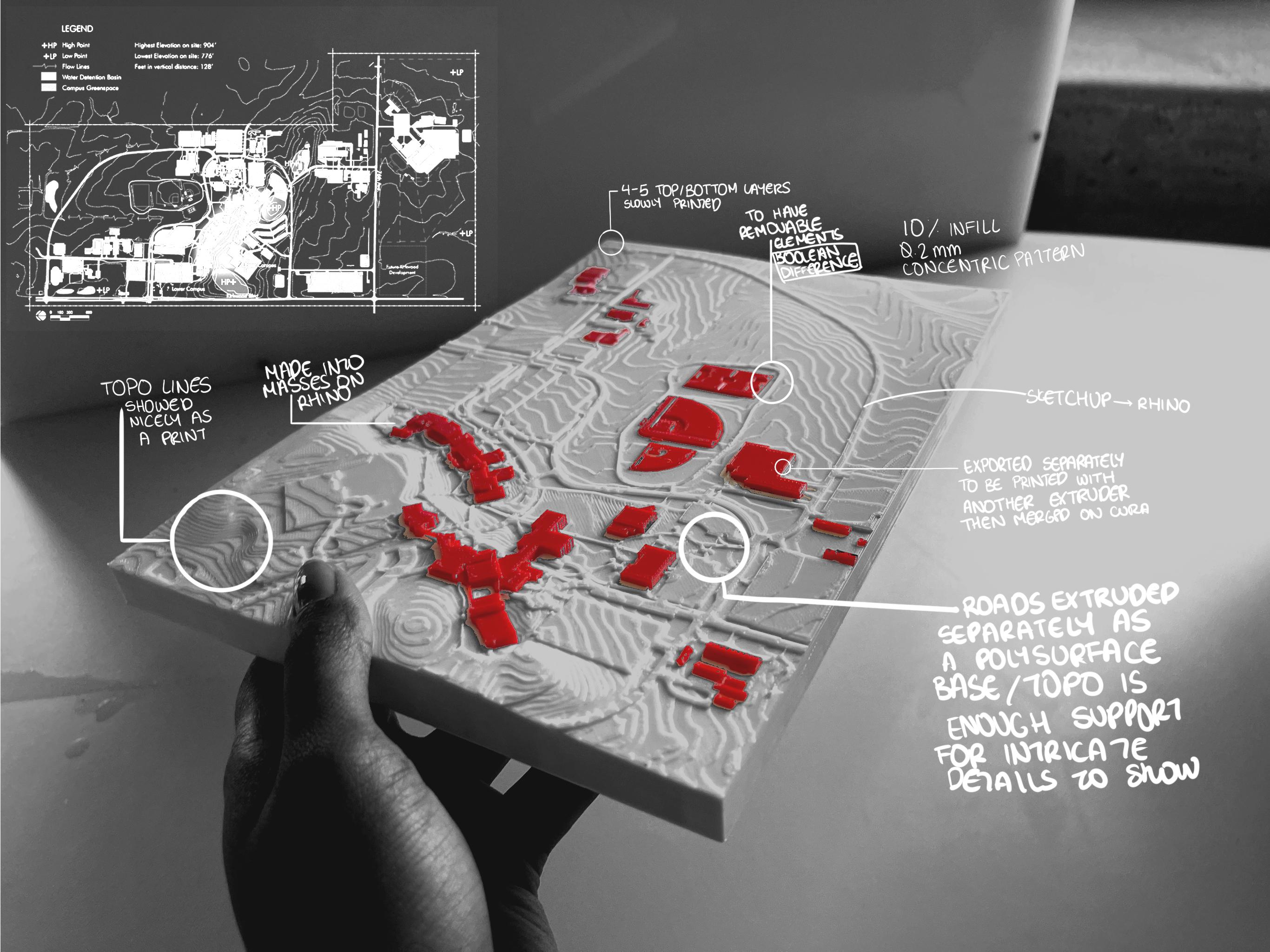
HOW TO PREP USING SKETCHUP + RHINO

1 2 3
In SketchUp:
1A Isolate just the ground surface (roads + site topography)
1B Select the entire ground surface and Ctrl + C to Copy.
1C Then in a new SketchUp File go to Edit > Paste in Place and save the file.
Next to export the roads:
2A Given all roads have the same material, right click a road to see a menu and then go to Select > All with Same Material. Then Ctrl + C to Copy the roads.
2B Then in a new Sketchup File, go to Edit > Paste in Place and save the file. This will give you just the roads in the exact position as the base file for easier exporting/manipulation.
Now Open Rhino:
3A Go to File > Import and select the SketchUp file of the entire base.
3B he file will import as open meshes. Select all meshes and then use the “Join” command to make 1 open mesh.
3C Next, we need to create new border for the base. In top view, use the “Rectangle” command to draw new boundaries. Then find this curve and extrude it so that is completely intersects the open mesh. Use the “MeshSplit” command and select the extruded rectangle as the object to split and then the site mesh as the cutting object.
3D Repeat the process again, this time selecting the site mesh as the object to split and the extrud ed rectangle as the cutting object.
3E Draw a rectangle mesh on the bottom of the base and then join the site mesh, sides, and bottom mesh to create 1 mesh.
3F Use the “FillMeshHoles” or “MatchMeshEdge” commands to decrease the amount of naked edg es. (more naked edges = bad)
CONTRIBUTORS’ QUOTES
“Design and construction have always been connected, but with varying levels of abstraction throughout the process. We have gone from individual artisans and builders that design as they build to a more commodified process where designers produce instructions to another party on what to build. With all its efficiencies, a lot of knowledge can be lost by these groups communicating less. With the advent of digital fabrication techniques and rapid prototyping, designers can have more meaningful dialogue with everyone in the design process by removing abstraction where necessary and understanding better how even the smallest design decisions impact the space they are creating.”
“Digital fabrication is a new lens by which we can look at buildings. It can offer a dynamic way to develop perspective on currently working concepts through adding the physical restraints commonly not present in digital solutions.”
“Digital fabrication has the potential to have far reaching impacts on the construction industry and how we address the climate. By building more intelligently and efficiently, we have the capability to reduce waste and create unique design solutions that address multiple problems at once.”
3A Loading the filament is a simple process by selecting the machine icon (icon) and following the steps on the screen.
2B After ensuring that the material is fully loaded and has extruded properly, send your file to print over the cloud on the CURA software
4A After your print has completed and cooled down, carefully remove the glass plate from the base (CAUTION: HOT)

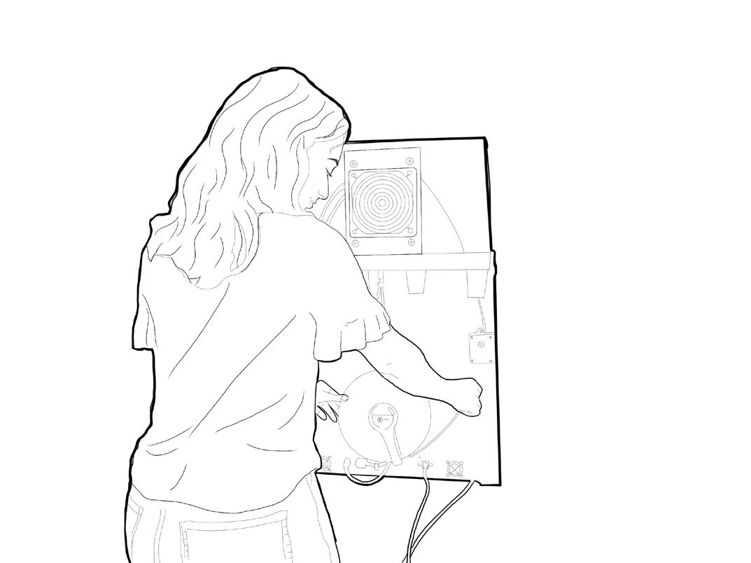
4B Now for the removal process! There are a couple of ways to get your build off the plate.
1. Rinse the back of the glass plate with cold water to cool down the print
2. Run warm water over the build to debond the glue
3. These steps might make this one easier: Using the scrape tool to remove the print. Carefully but firmly scraping your build off the plate requires some force, but be careful to not let the tool slip or from damaging the glass plate.
4C Yay! The print is completed and looks great. If you have used (PVA) dissolvable filament proceed to step 4 you have not, proceed to step
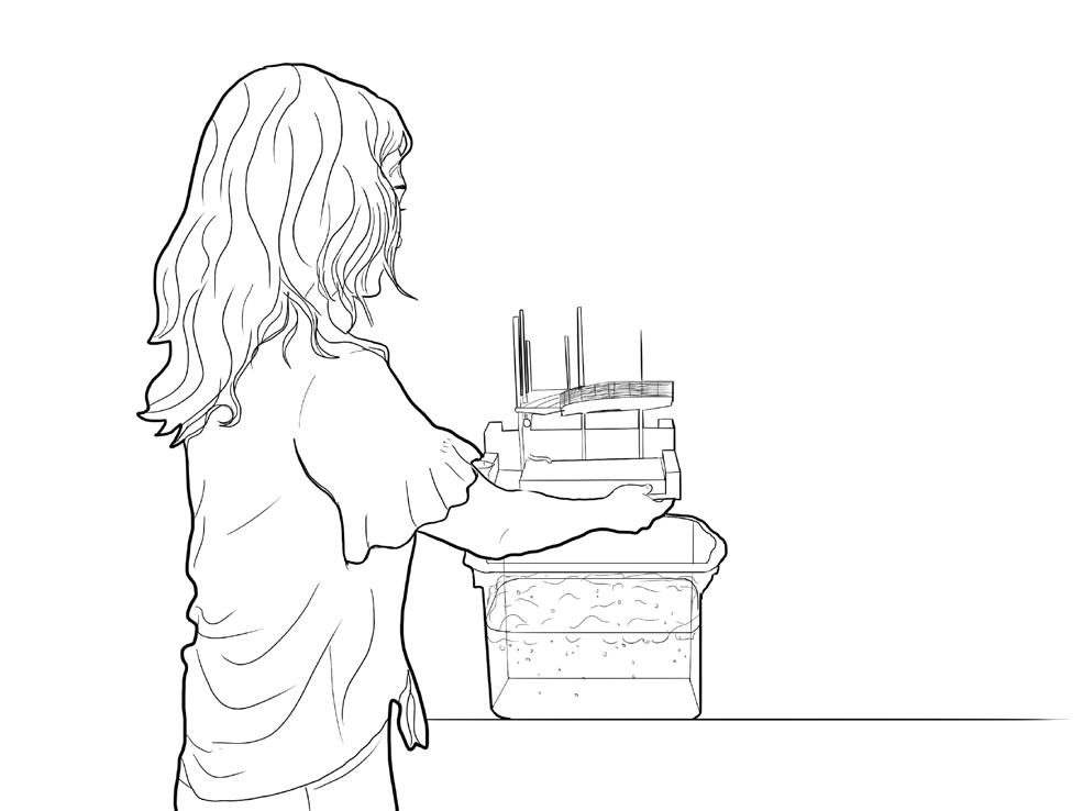
4A Fill a tub with lukewarm water + dish soap and carefully place your awesome print into the tub. Fill smaller tub or container with water and place over the print to prevent from floating to the top
4B PVA will dissolve in lukewarm water + dishsoap. It is best to leave your print overnight to completely dissolve supports
4C After your print’s supports are completely dissolved, let your print airdry and dispose of water into utility sink to prevent blockages. If your print needs further clean up from intricate dense supports then feel free to either break off with needlenose pliers or let it soak some more! Enjoy!
DIGITAL FABRICATION
IOWA STATE UNIVERSITY COMPUTATION + CONSTRUCTION LAB
3D PRINTING + CASTING

CNC + CASTING
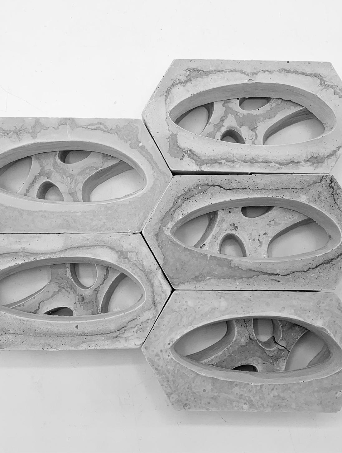
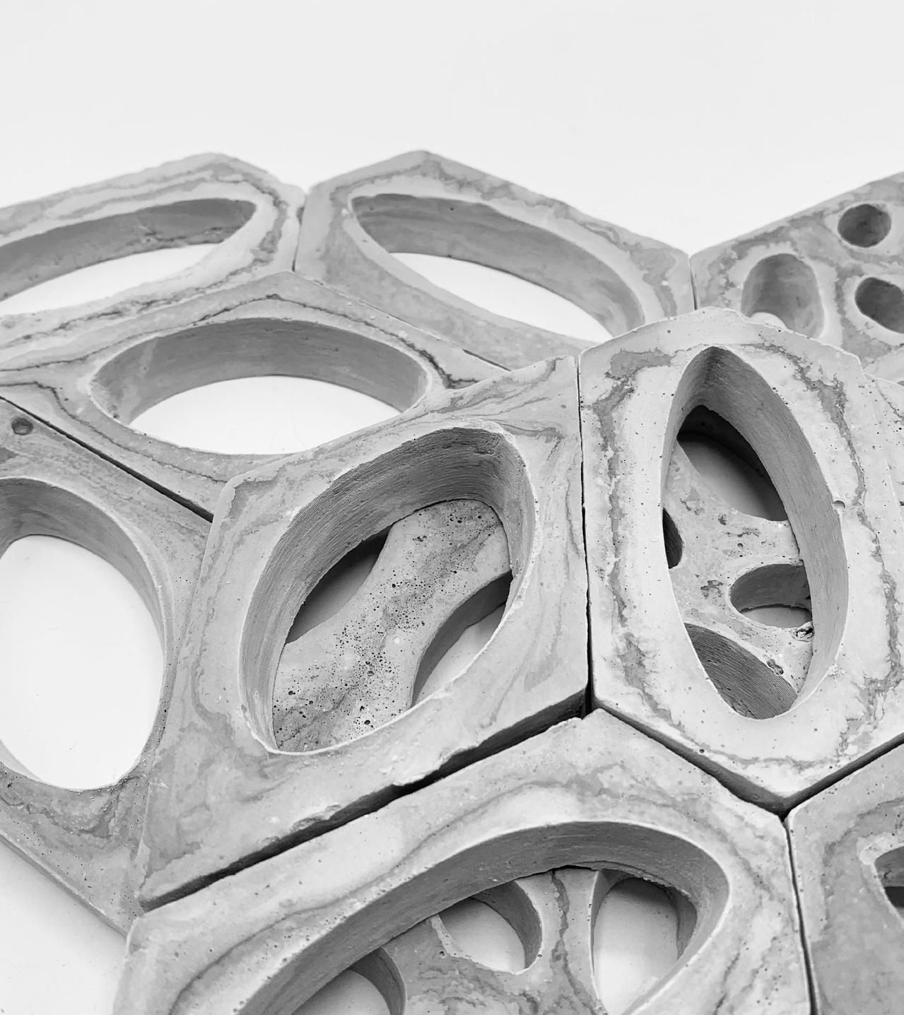
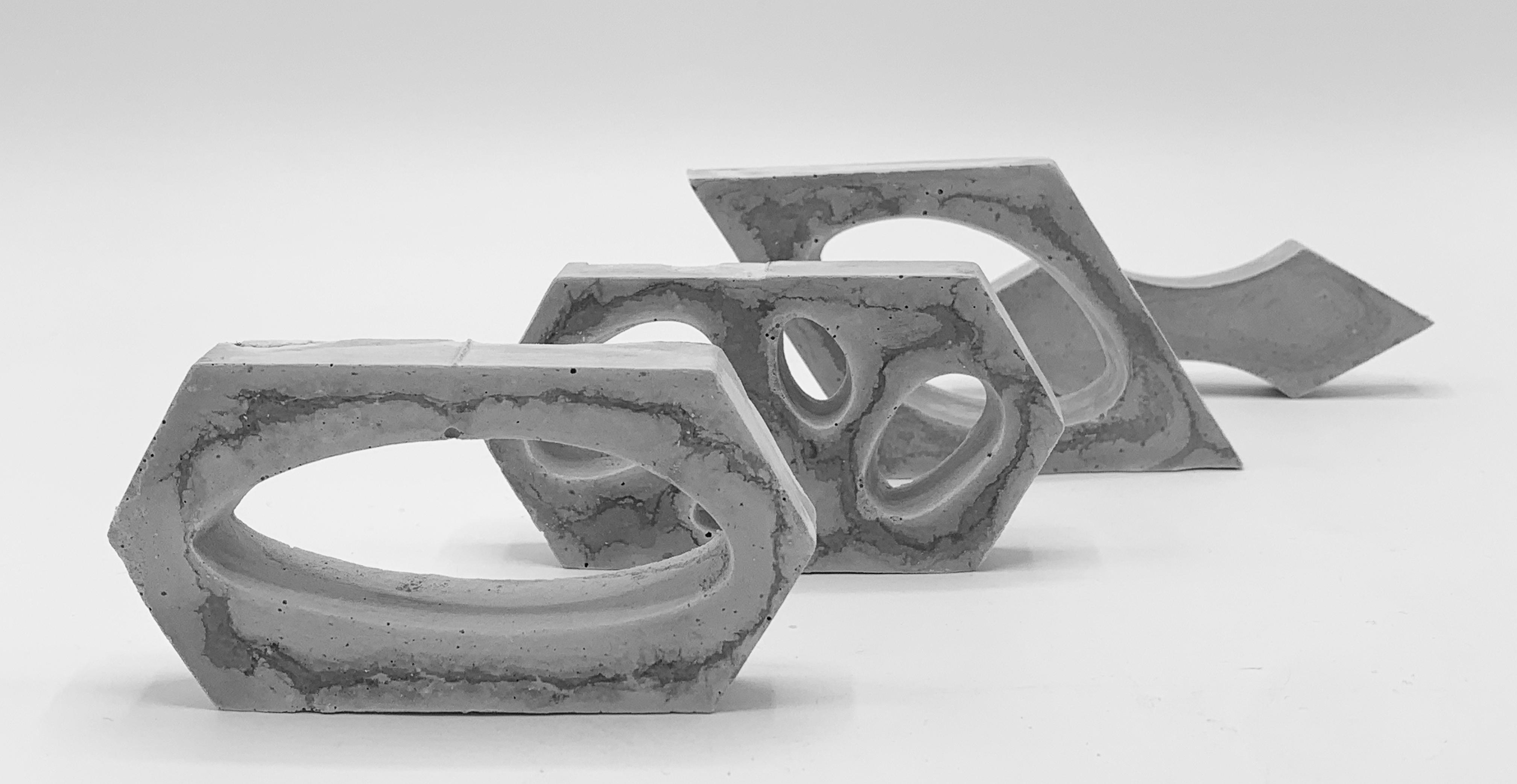
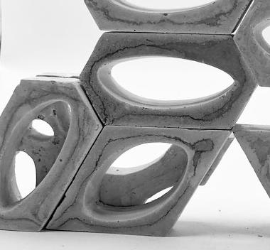
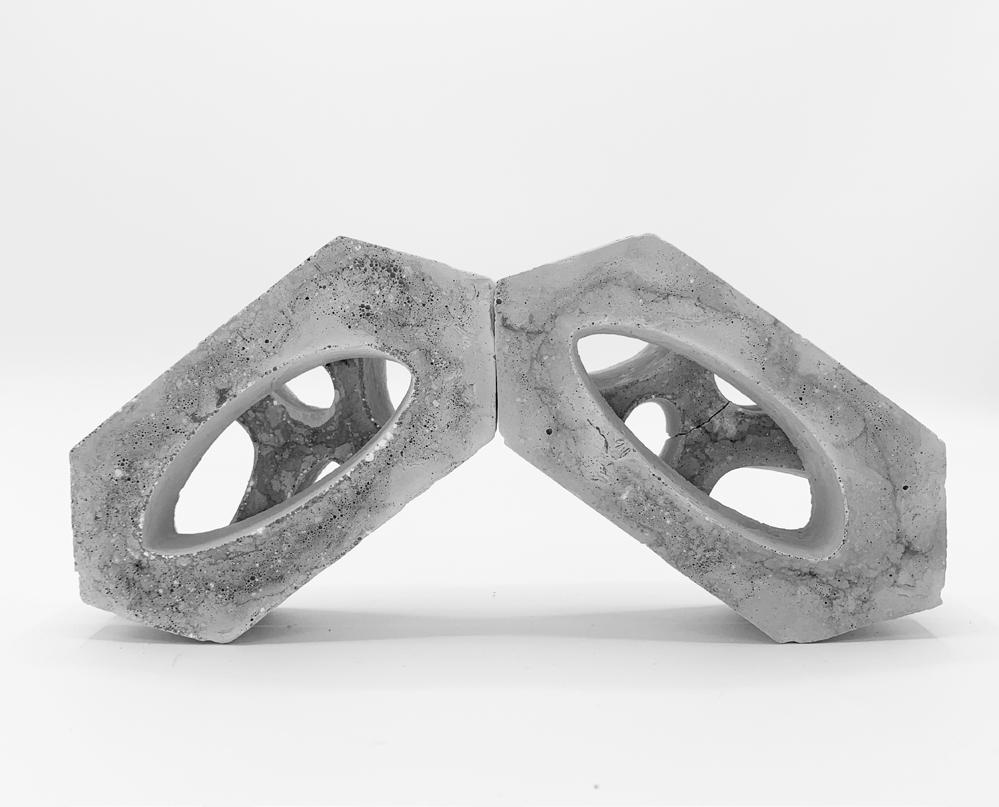
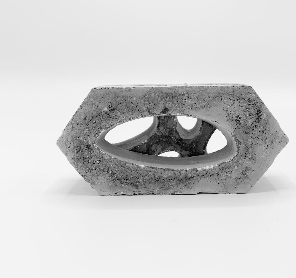
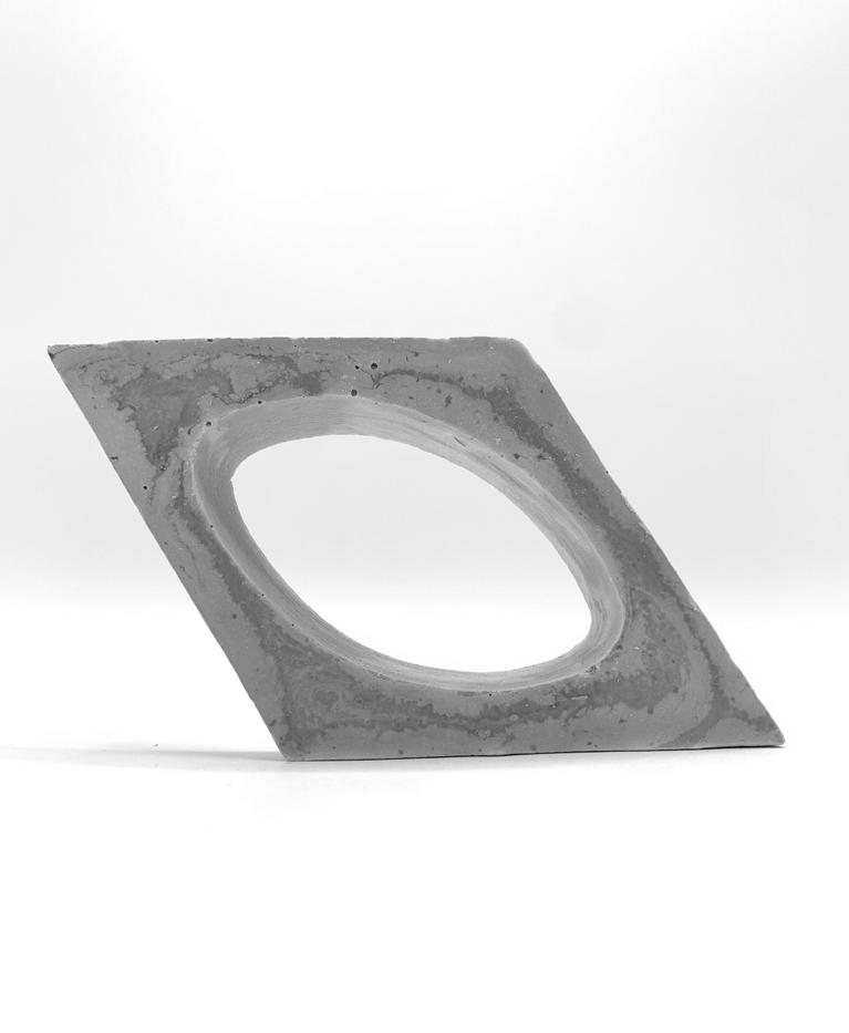
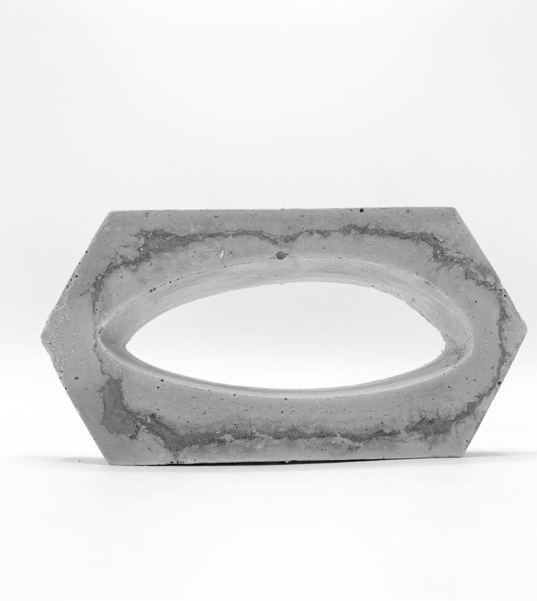
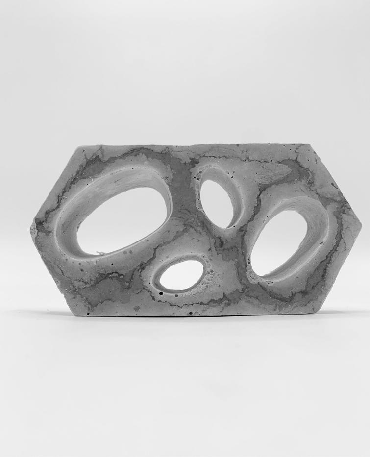
CERAMIC 3D PRINTING the mold the cast the module
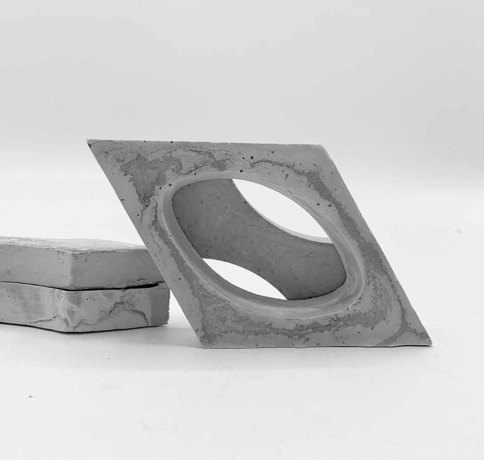

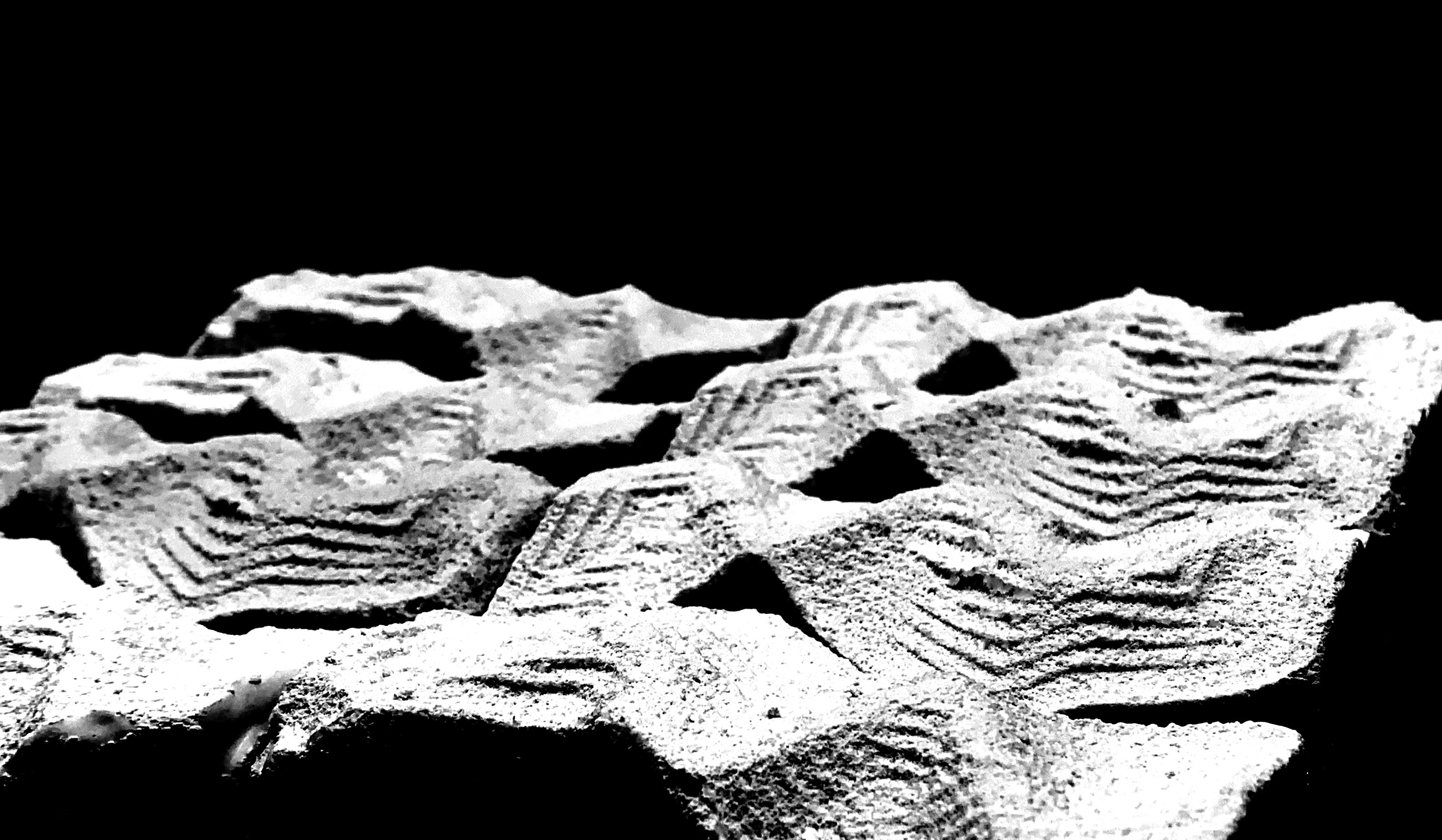
In our final iteration, we made fine adjustments to our previous test molds (adjusting the angle, void placements, etc.). We also decided to add two new shapes: a diamond with one central void and a diamond with voids taken out of two sides. In assembly, these shapes all fit together into one large hexagon, with the diamonds in the center. Along with our two iterations of hexagons, these two versions of diamonds also allow us to layer the pieces on top of one another, mimicking the effect of our precedent Mashrabiya panels and paneled façade.When casting these molds, we ran into some issues with 3D printing and scaling, and had to print some molds multiple times because they would not fit together properly. In addition, we experienced some issues with void placement specifically on the hexagon with four voids. Some points within the shape had become too thin, as we had altered the outside shape just a tad, which then affected the placement of the voids within the containing shape. This particular shape gave us a lot of trouble, we were sure that it would work because it had before, but removing the cast from the mold without breaking it was difficult. The inclusion of many pieces within one cast created a lot of pressure on each internal piece as the concrete expanded as it dried. However, even though we had several unexpected challenges with these final casts, we eventually got the casting method down and were able to cast many successful pieces. The result of these casts was an array of intricate assemblies comprised of simple, crisp modules. We were very happy with the flexibility and variation of our pieces, as well as the fact that we had kept many of our central design principles from the very first iteration. The forms we created were simple, showed a relationship to organic forms (present in the voids), had variable transparency, fit together almost seamlessly, created depth and layering, and utilized void both in assembly and through each individual module.

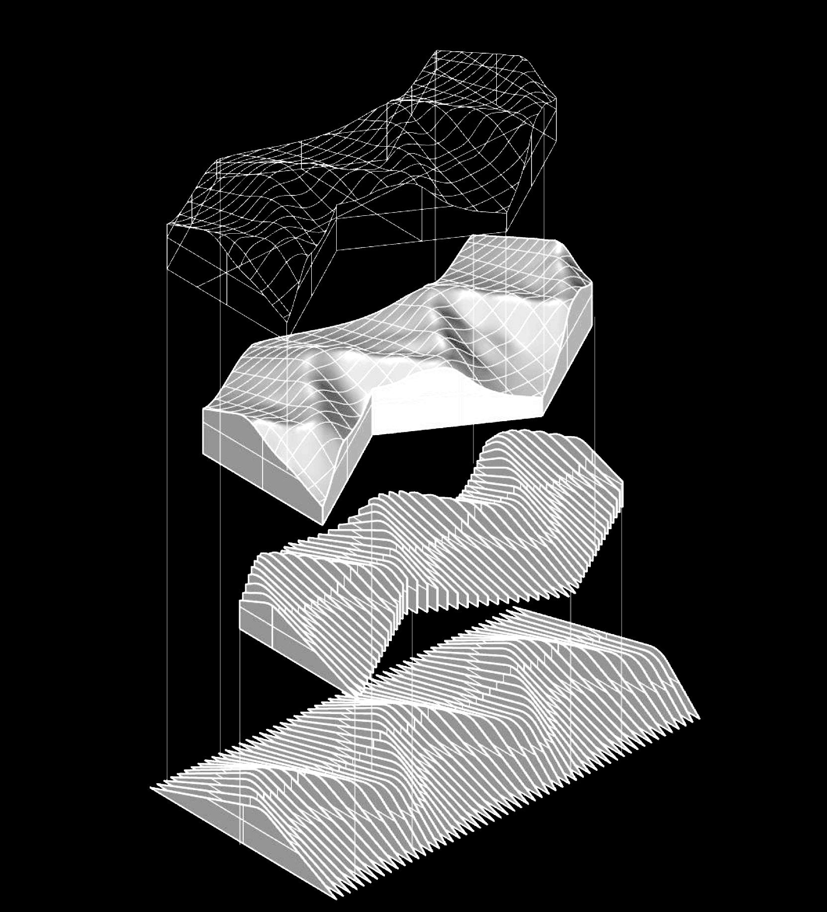
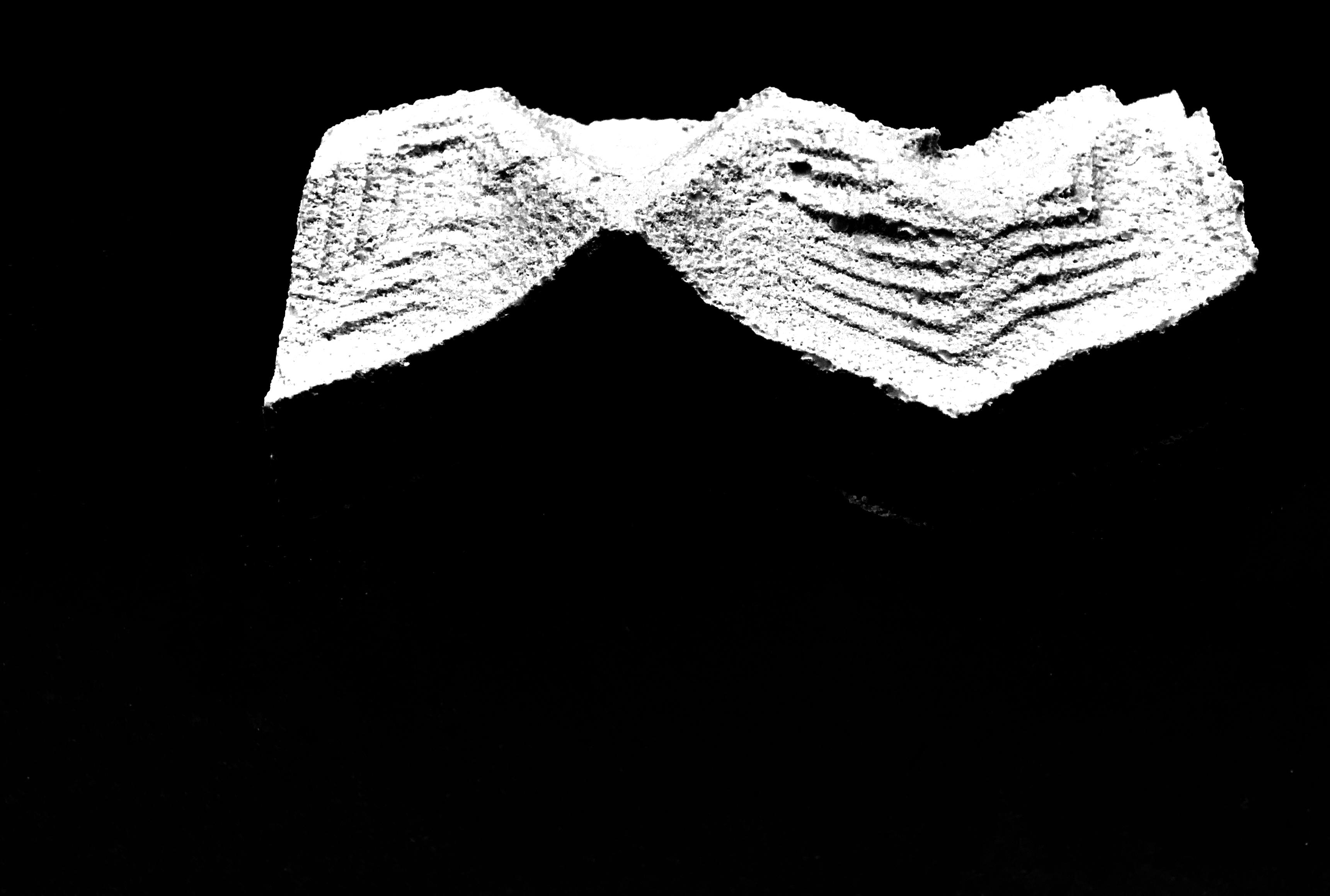
This project challenges our ability to think through the process of fabrication in a sequence that operates backwards to Project 1. Rather than creating the negative of our project, we needed to consider the positive to be CNC milled to then become a negative mold when casting silicone. This process of adding and subtracting forms influenced our final iteration- an organic texture that is confined to a rigid geometry. An undulating module that represents the additive and subtractive nature of the process of this project, first began with deconstructing our understanding of modularity through curved forms. Using grasshopper to generate a script that achieves an organic form with parametrics inspired the rest of the project. We then had to simplify our iterations to get to a conclusion of understanding.