11. First fix (carpentry, M&E services, drylining, fire stopping and windows) – P72
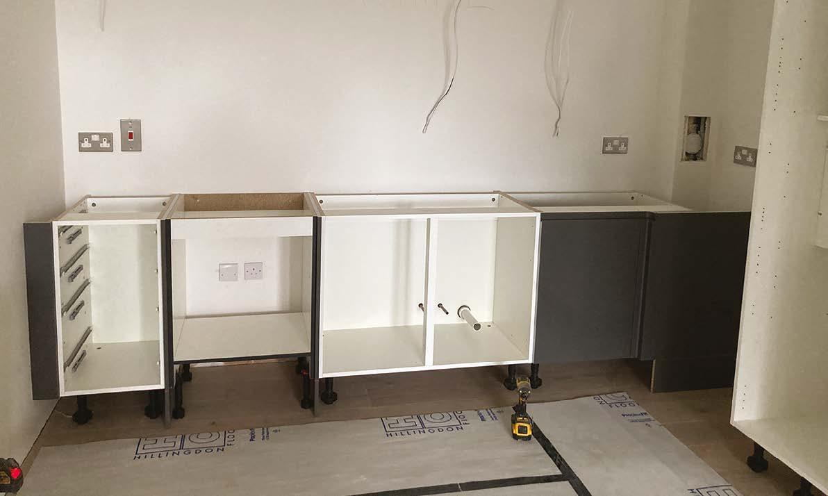
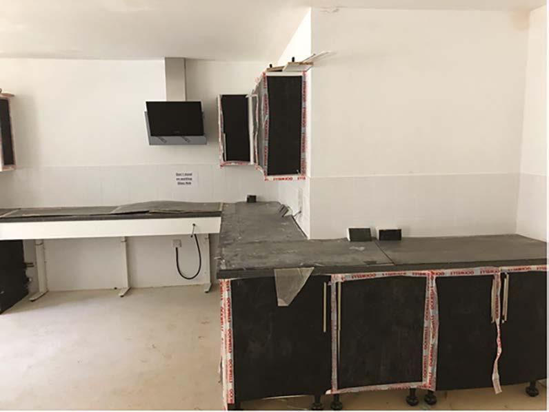
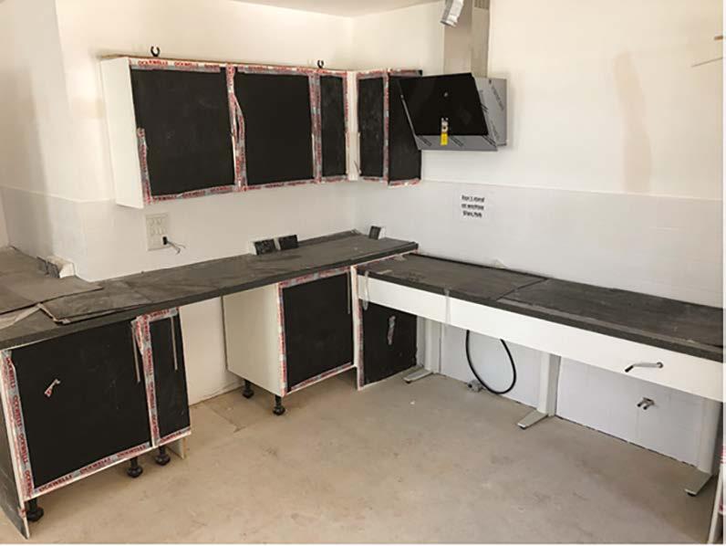
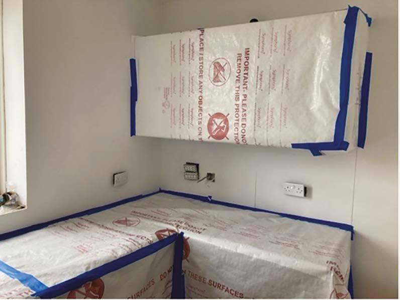
12. Second fix (carpentry, kitchens, M&E) – P93
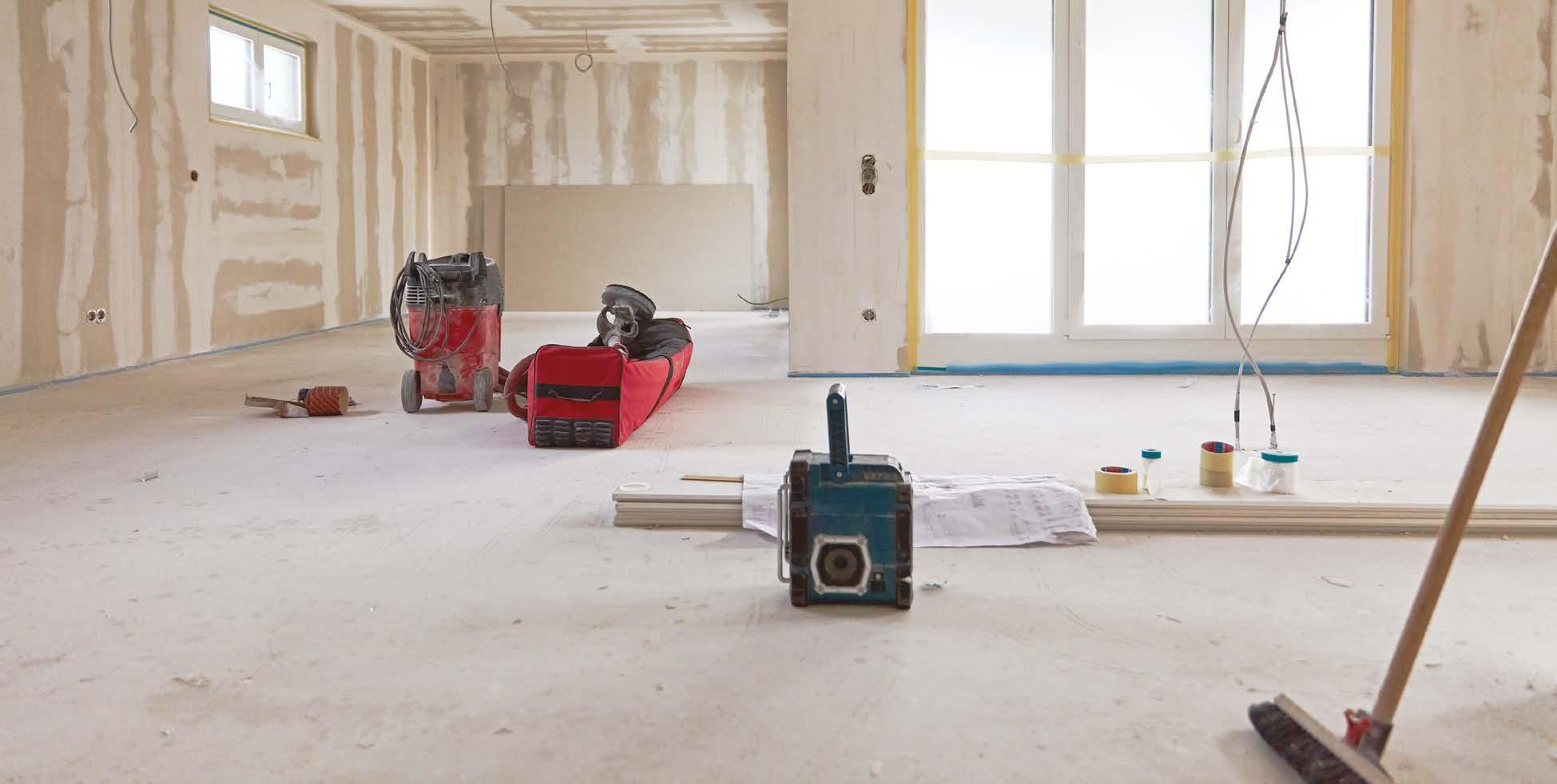
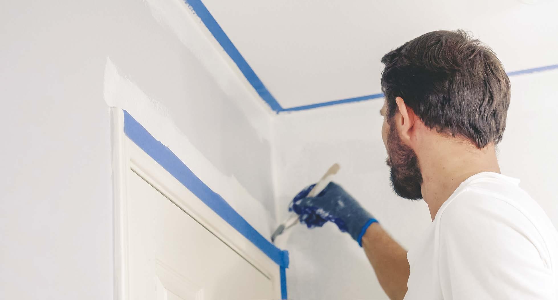
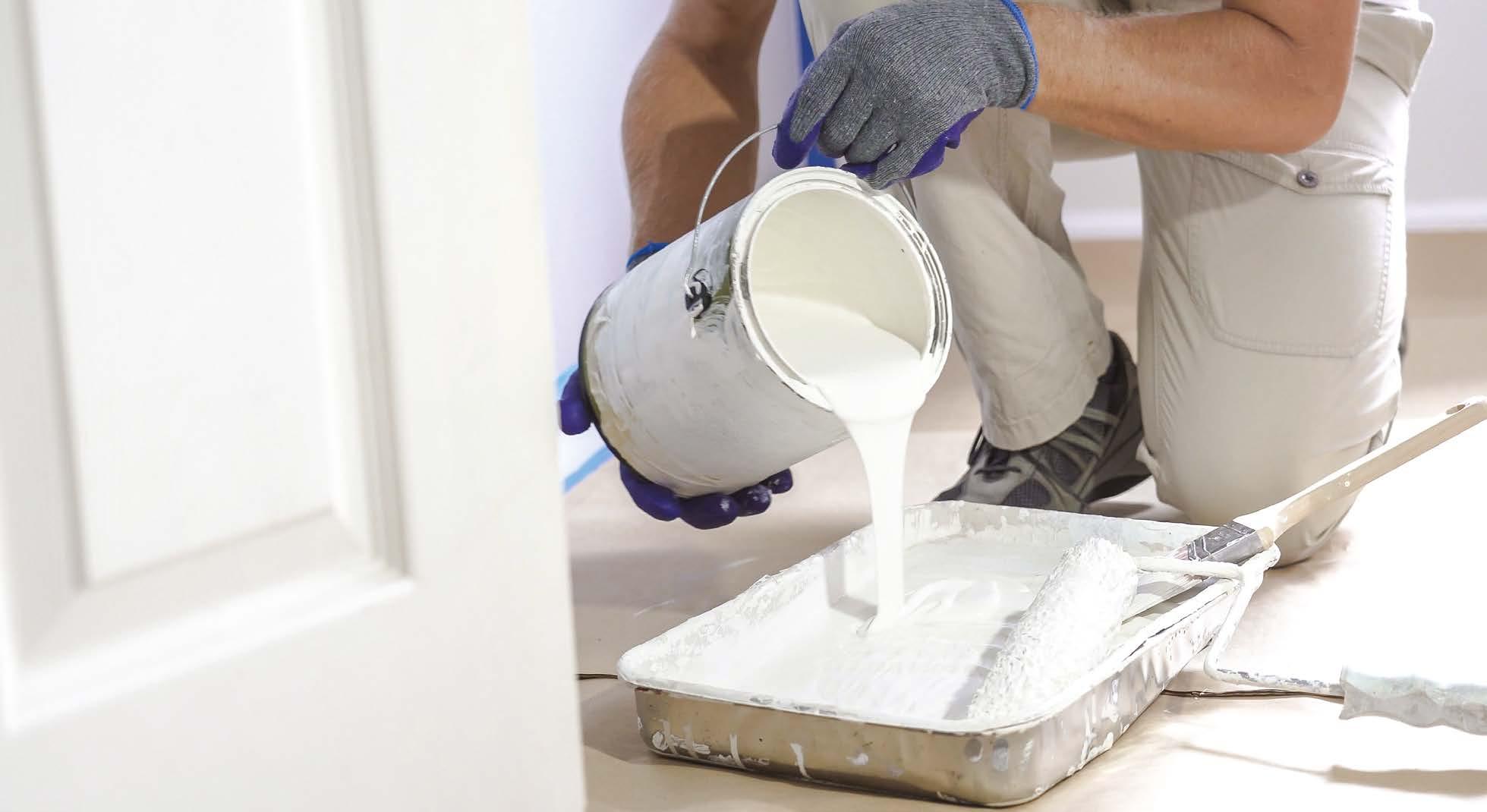
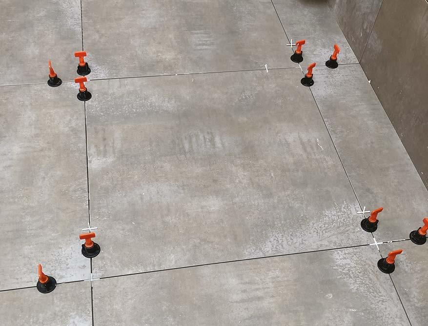
13. Finishes – P110
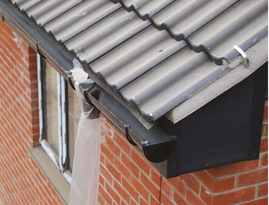
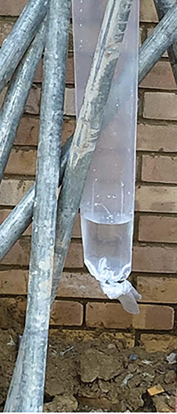
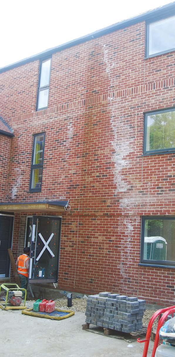
14. Moisture and mould in new homes – P126
15. External works – P128
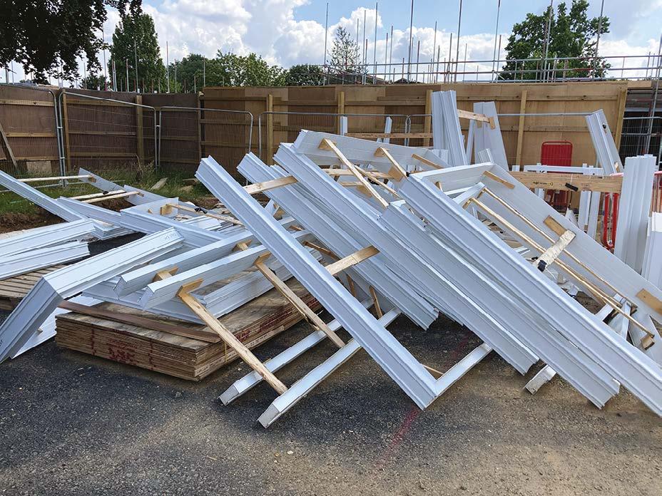
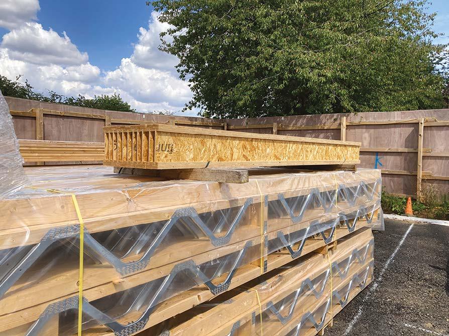
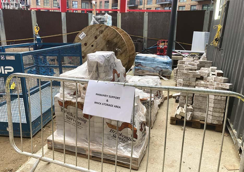
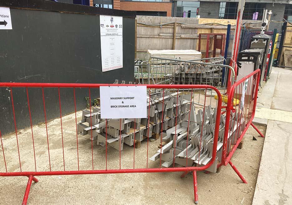
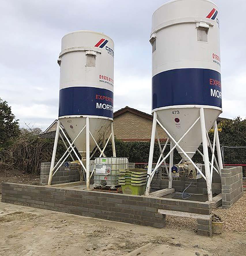
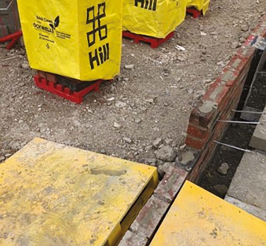
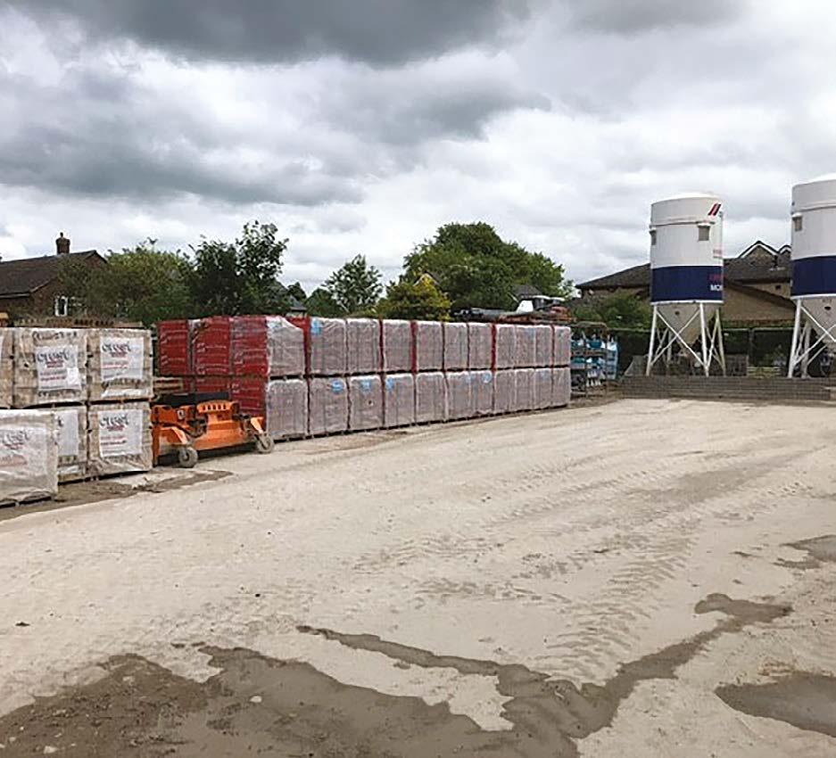
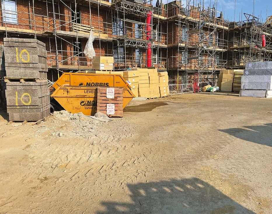
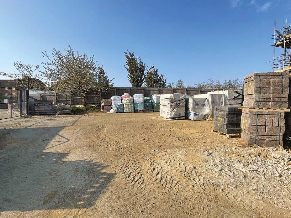
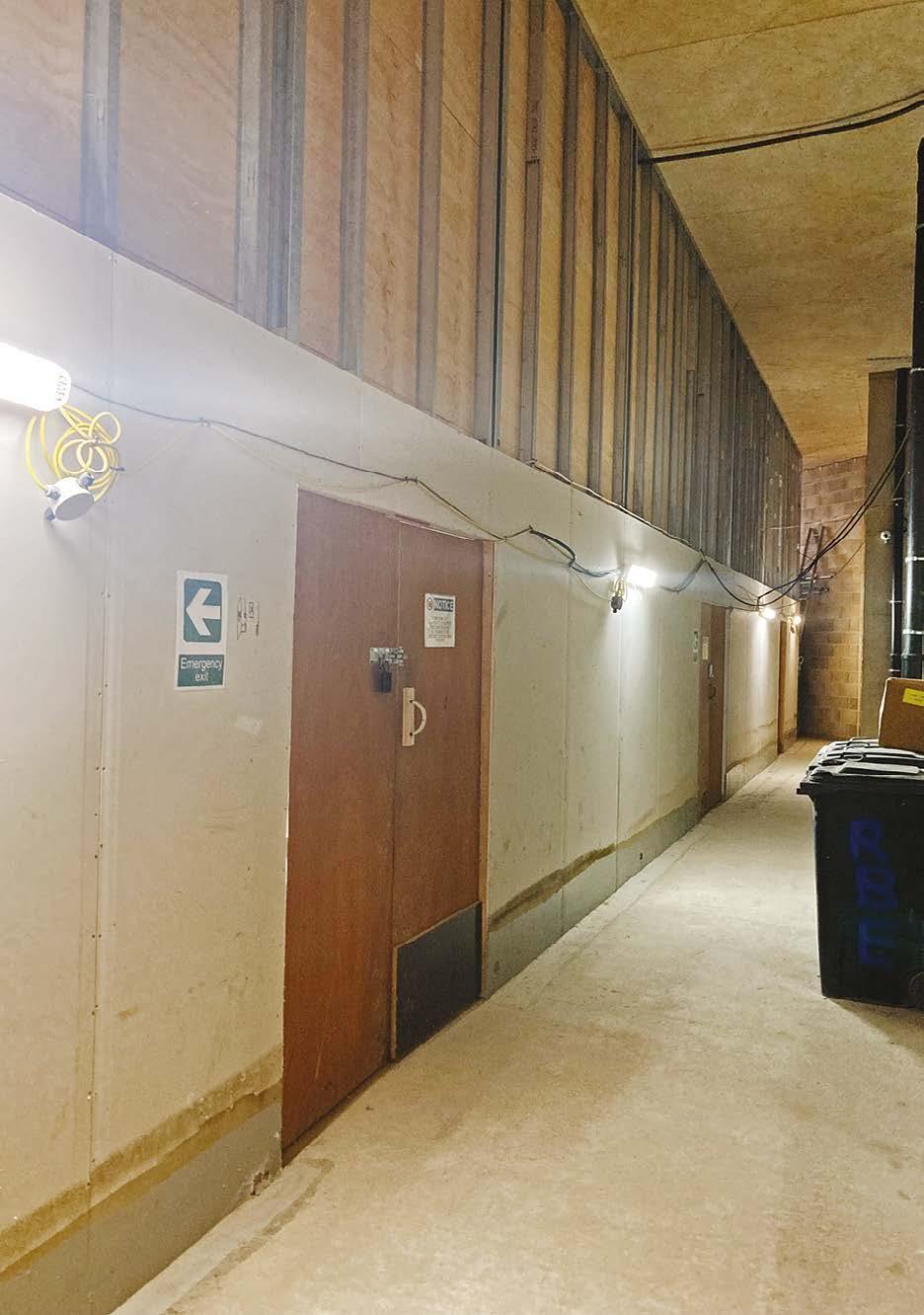
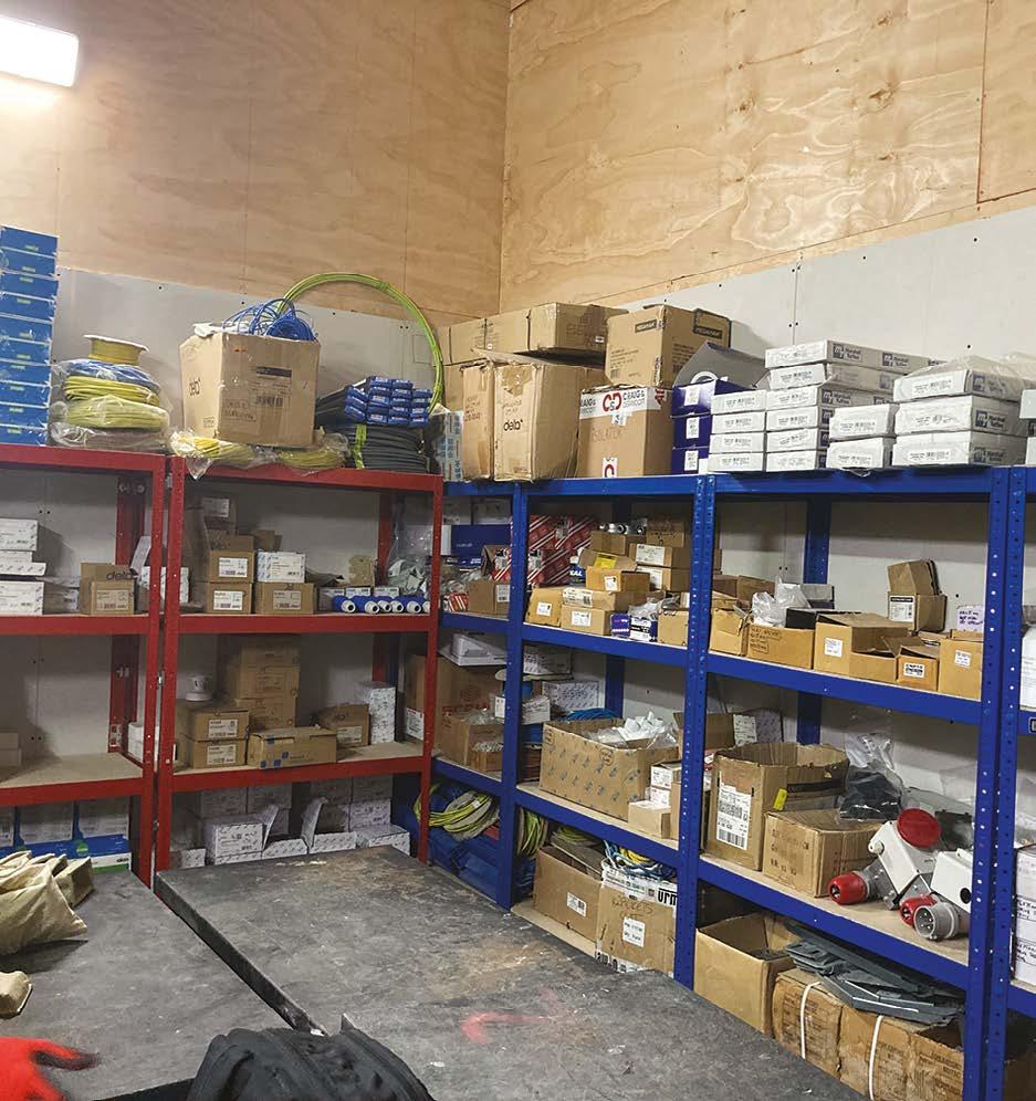
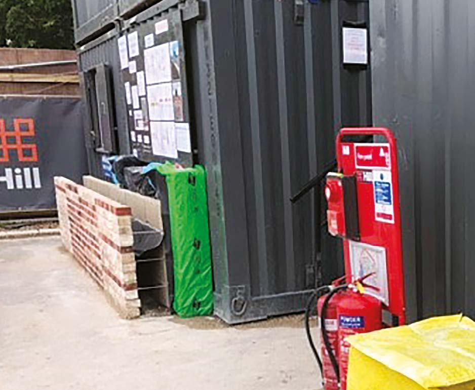
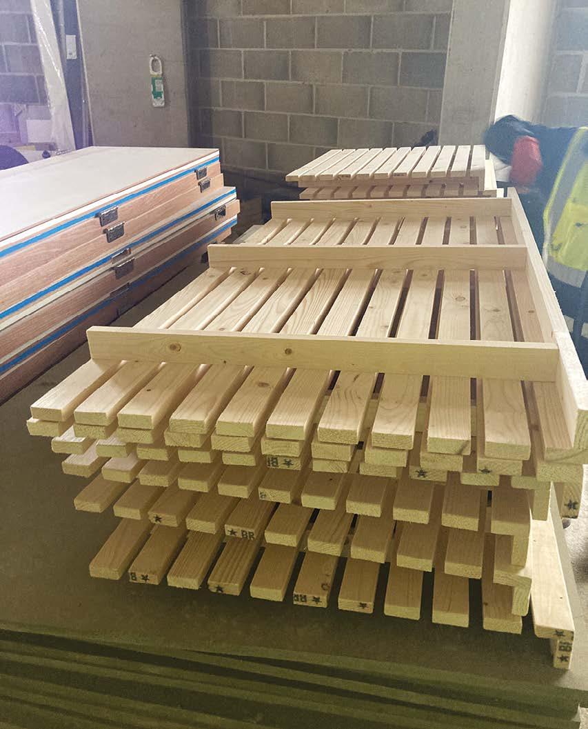
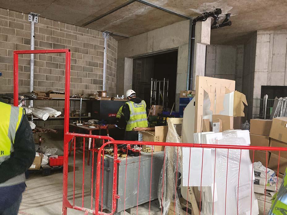
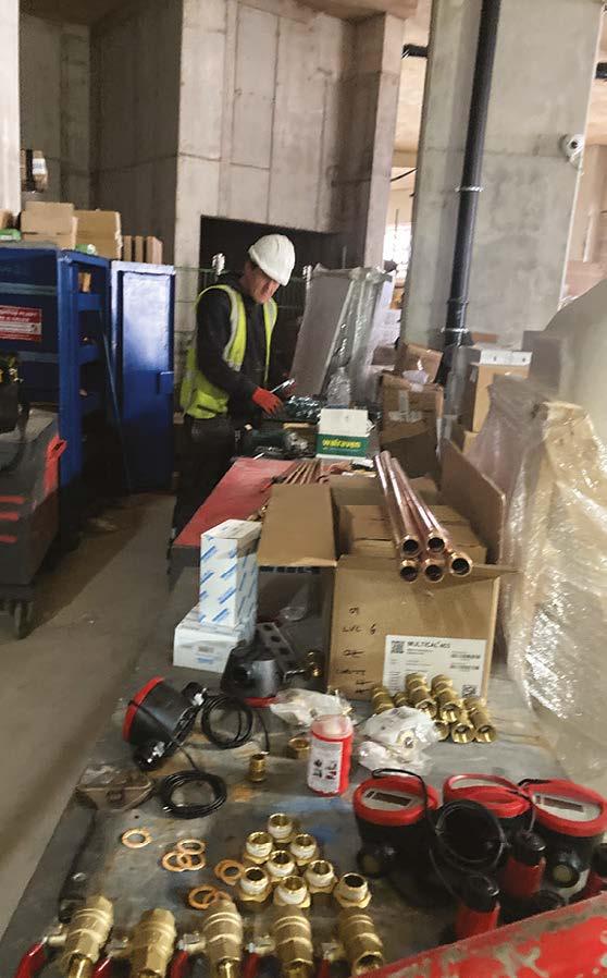
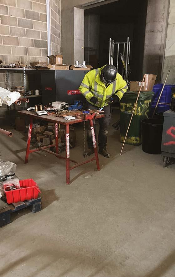
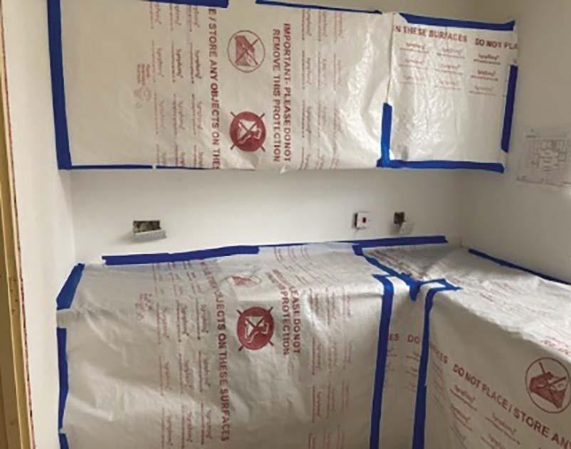
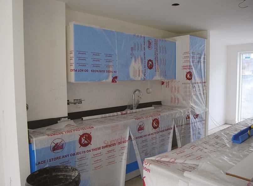
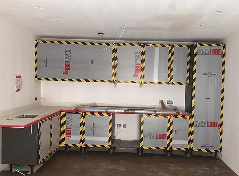
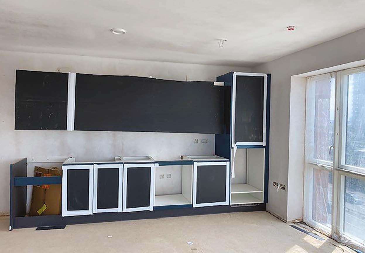
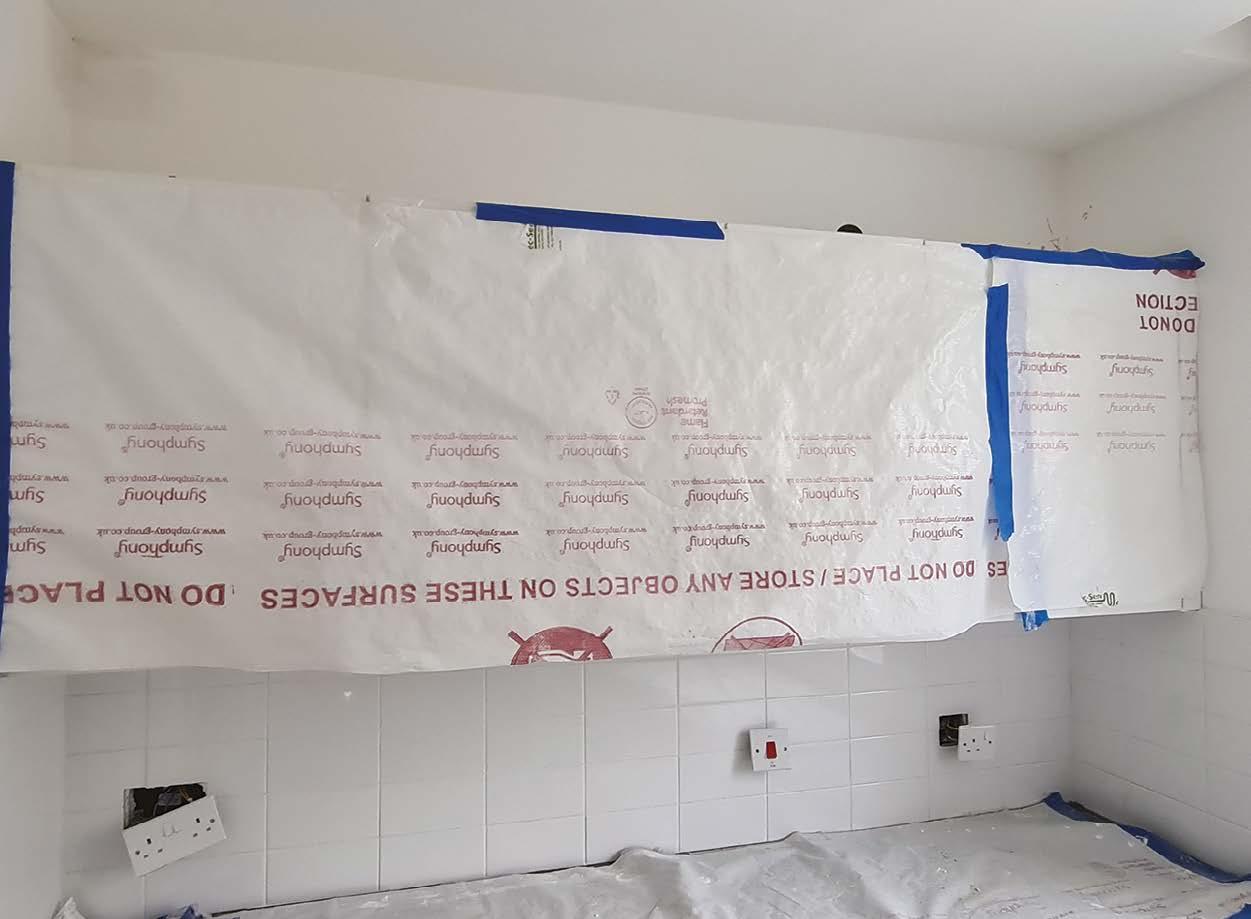
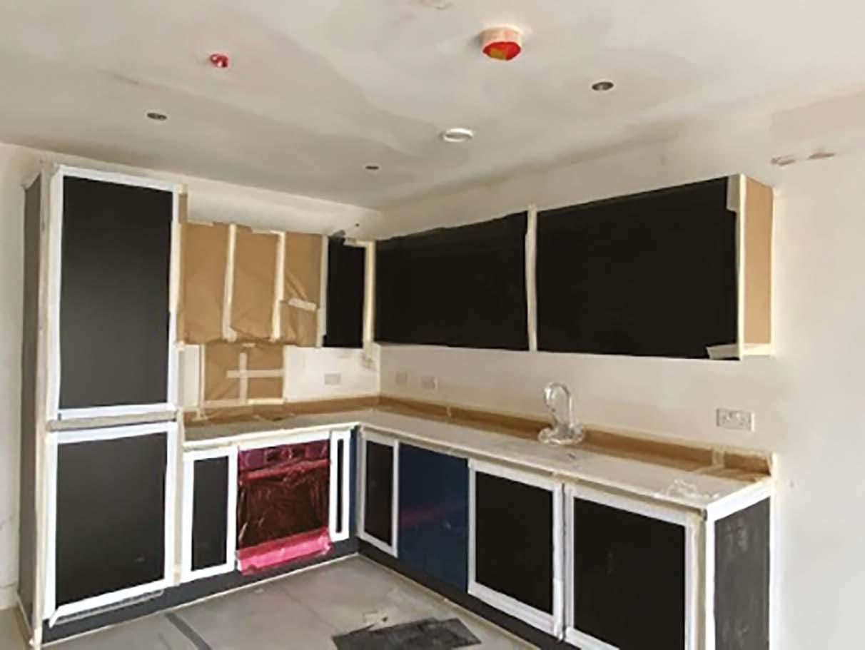
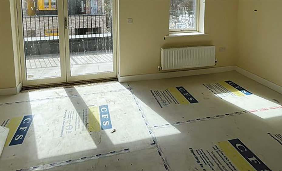
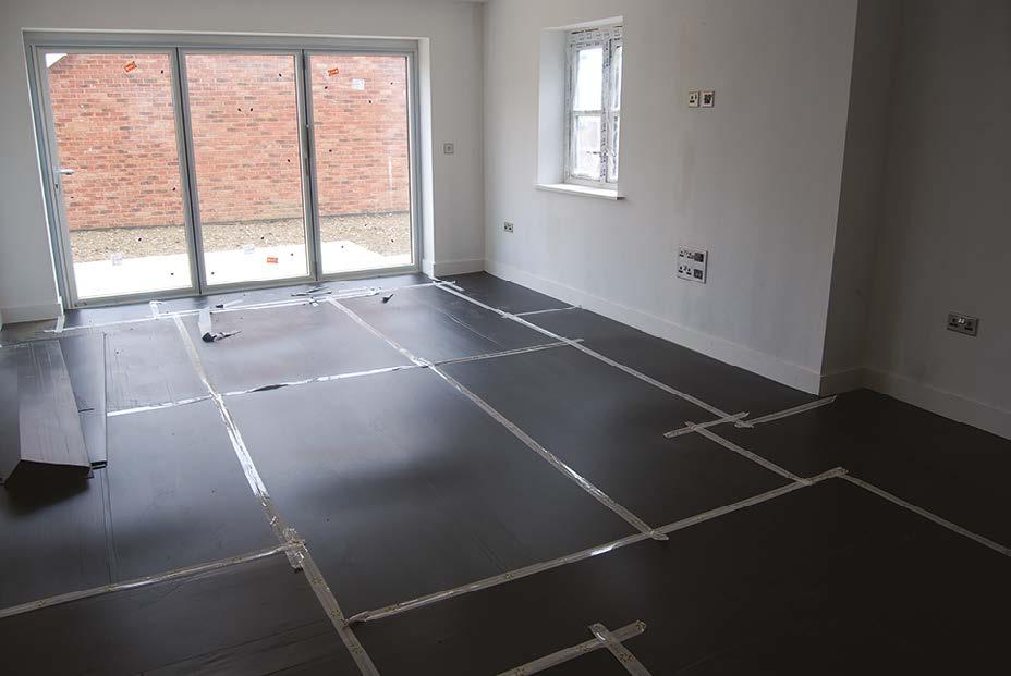
16. Materials storage, organisation and protection – P129
Hill Good Practice Guide
Hill has established an enviable reputation for the quality of the new homes it builds.
This reputation has resulted in continued recognition through multiple industry awards, including the prestigious WhatHouse? Housebuilder of the Year Award three times in the last decade, and our status as a 5* housebuilder.
Our reputation for an uncompromising approach to quality has been hard earned, but like all good reputations, it is only as good as our last project and is easily lost.
As our business grows, we face challenges ensuring quality is maintained consistently across all corners of the Group and it is extremely important that best practice is shared.
To assist in delivering consistently high quality across our business, this Good Practice Guide, which establishes clear standards and best practices, should be used as a benchmark across all Hill sites.
I hope this document will be useful to you in maintaining our quality reputation for decades to come.
Andy Hill, OBE Group Chief Executive
All of us within The Hill Group strive to deliver high-quality new homes, whether large premium-spec homes or smaller affordable homes for social housing providers. Here at Hill, our quality standards are tenure blind, with all of our homes benefitting from robust quality systems and expectations.
The difference between providing average quality and good or exceptional quality typically boils down to the uncompromising standards and attention to detail from our teams.
We have launched this Good Practice Guide to provide clear benchmark examples of good or exemplary works, highlighting what minimum standards we expect at Hill and to rebuff some who might think that such quality is impossible to achieve.
We should all strive to match the quality standards included in this guide and deliver this consistently across each and every Hill Group project.
Remember that the quality of the homes we build is not just a ‘production issue’. Delivering quality is very much a team effort and other departments also play an important role in delivering highquality finished homes.
It is recognised that specifications do vary across projects and the homes we build. Good quality is however a universal message and the content of this guide can be applied across all types of developments.
For ease of reference, this guide is divided into recognised key work stages. This should enable the chapters to be applied to relevant subcontractor works packages.
I hope you find this guide useful in delivering quality standards that make you proud to be part of Team Hill.
Andy Mullins, FCIOB, C.Build E FCABE Group Head of Quality
3. Managing Quality
The Hill Process
Hill have a robust quality control procedure which includes the inspection and recording of constructed works via checklists on a digitised platform. This feeds into the ‘Golden thread of Information’ as evidence that we have constructed the works in accordance with the drawings and specifications.
Our process relies on our supply chain to sign off completed work stages that we verify through spot checking. The frequency of verification depends on the criticality of the works in question and our trust in the competence and thoroughness of the subcontractors concerned.
Additionally, we have specific ‘hold point’ inspections that are required to be completed before works can progress beyond that point.
These hold point inspections are:
1. Pre-Plaster
2. Pre-Decoration
3. Final Inspection Commissioning Checklist (FICC)
4. Ready To Move In (RTMI) – applicable on Hill Residential projects only.
y Structure
y Roof
y 1st fix
y Fire stopping
y Close up walls and ceilings
y Plastering
y 2nd fix
y Fittings
y Vinyl floring
y Tiling
y Decoration
y Soft flooring
y Commissioning
y Finals
to move in (RTMI)
How do you make a difference?
Having a structured quality process only goes so far in delivering quality. In relation to quality, what sets our best performing managers apart from the rest?
y Plan ahead: Think ahead and brush up on your technical knowledge where required prior to each work stage commencing. Engage with sources of help and support where needed.
y Briefing: At every opportunity, when a new element of work is underway, meet with the subcontractor and discuss what you expect from them. Run through the design and also any relevant Hill technical policies, this Good Practice Guice, NHBC / LABC technical standards and other sources of guidance.
y Benchmarking: Agree with the subcontractor that the works are to only to progress to a preagreed stage, at which point this work is to be inspected by our site manager to ensure that it is of sufficiently high standard. This bar must be set high, as it is to be expected that standards may slip slightly from this over time – so give yourself some headroom. Involve others in this if necessary such as our Quality Team (including M&E) and third party ‘experts’. Remember that NHBC offer a benchmarking inspection at the first key stage inspections. Periodically these benchmark inspections may have to be repeated if quality slippage is observed or if there has been a change of operatives / supervision.
y Create unofficial mini-hold points to ensure that you give yourself early opportunities to intervene should action be needed. A regular gentle ‘touch of the tiller’ will always deliver better results than less frequent major course corrections. Check quality regularly and often.
y Set consistently high standards and be a proactive manager rather than a passive, reactive one. Do not accept or turn a blind eye to poor quality work and do not be afraid to implement a zero tolerance and reject or instruct works to be re-built. Make sure your subcontractors know what your high standards are, and the consequences for them if they stray from this. Walk the walk, make a difference and seek support if you need it.
y Share best practice and create a winning team culture. Celebrate and praise good work.
y Where necessary, escalate issues to senior subcontractor management and don’t forget to make an effort to share praise with them too.
4. Seasonal working
Working in all different weather conditions is unavoidable, as projects commence and progress at all times of the year and throughout all seasons.
Technical Guidance BQ036 covers ‘Cold Weather Working’ and the necessary precautions needed when working through cold winter months.
It is anticipated that our winters will become milder and wetter and summers hotter and drier in the future, which poses additional challenges.
Weather condition:
Cold: Refer to Technical Guidance BQ036 ‘Cold Weather Working.’
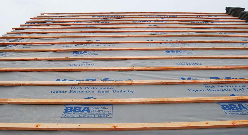
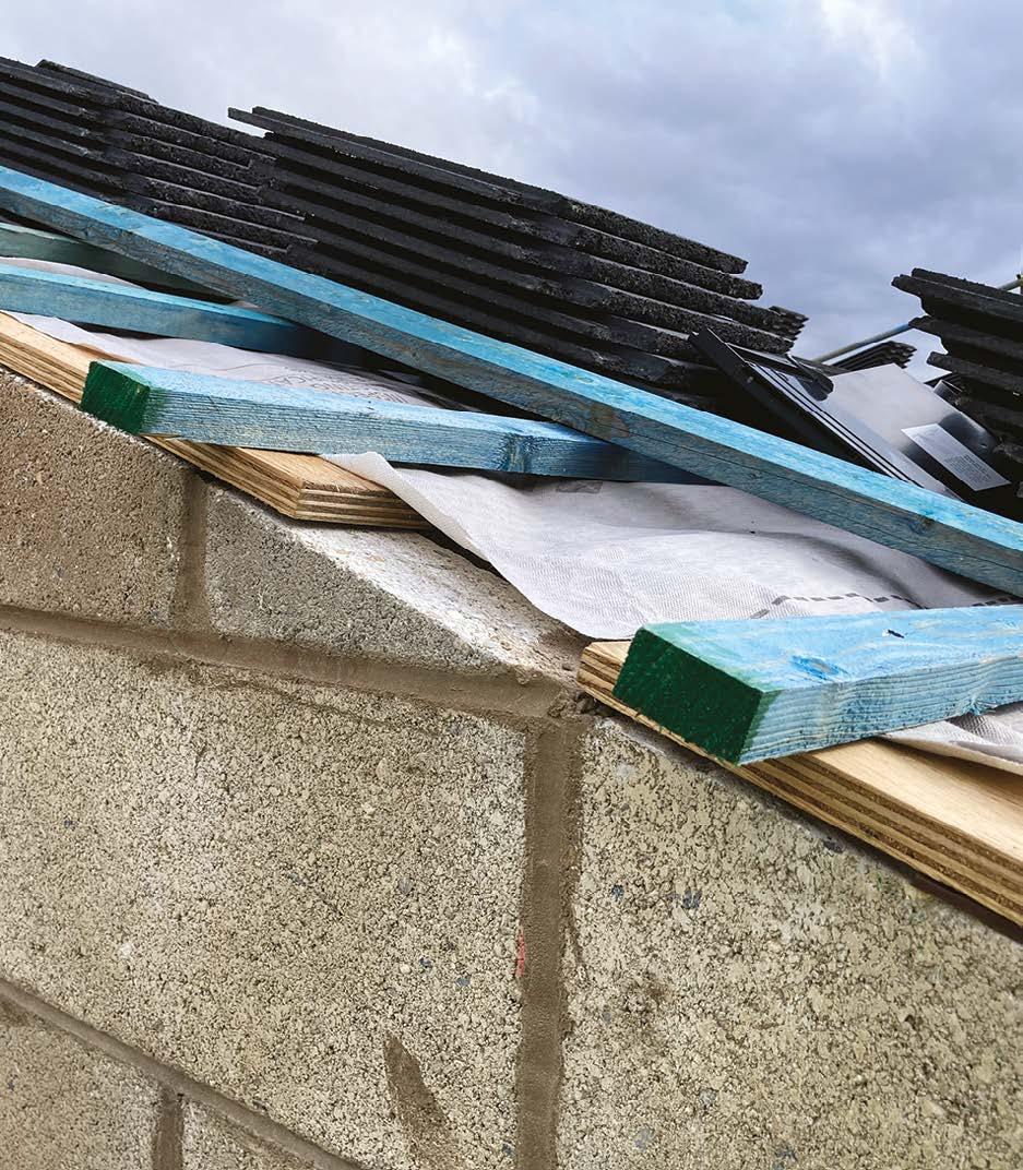
Wet: Consider the specification of products or systems as some require dry weatherproof conditions that may be practically impossible to achieve in wet conditions. In some cases products are wholly unsuitable for application in wet conditions (e.g. self-adhesive waterproof tanking membranes or hydrophilic strips). Ensure that materials are stored to prevent them becoming water damaged, excessively wet or contaminated by wet ground.
Walls and insulation should be protected from rainwater to limit the amount of water that is built in to the structure – and that has to subsequently dry out.
Ensure that internal materials are stored and installed in weather tight conditions.
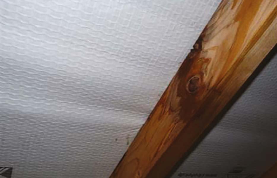
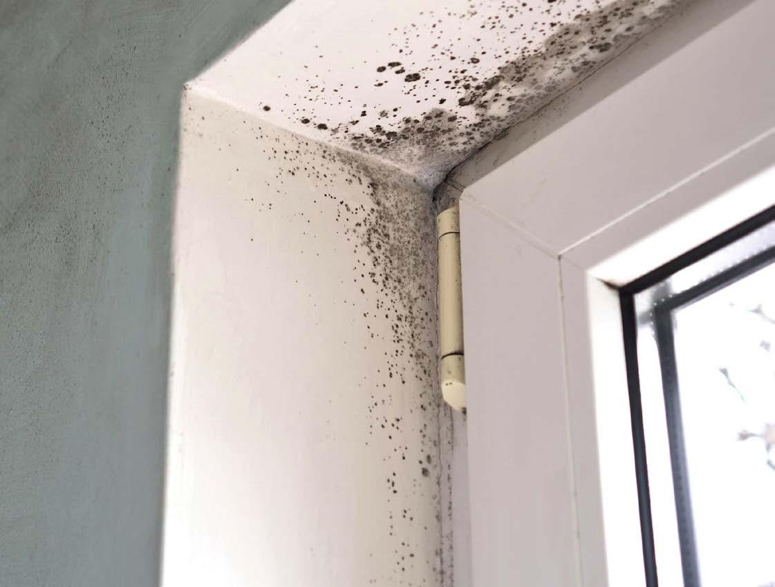
To avoid black mould, ensure that the structure has dried out sufficiently before drylining or applying dot and dab plasterboard (the walls should be <16% moisture content) and provide dehumidifiers, heating and ventilation to assist drying out where required.
Wind: Wind can damage partially constructed structural elements, sometimes catastrophically.
It can also have an accelerated drying effect on water-based products, which may prevent correct hydration or cause excessive drying shrinkage. Working time (before a product dries or sets) may also be reduced, causing application issues.
Geography and topography of the site may also play a part as some sites are more exposed to wind than others.
In such cases, temporary screening should be reviewed to mitigate this issue.
Hot weather: Much the same as wind, excessive heat can reduce working time and cause an accelerated drying/curing. This will however affect works internally and in sheltered areas as well as external works.
In many cases, product manufacturers do not endorse application of products in direct summer sunlight and screening may be required.
Substrates may need to be wetted if they have become too dry, to avoid excessive suction of moisture from subsequent applications (e.g. plaster or render), preventing correct hydration.
Paint and surface finishes may dry too quickly and may require thinning to aid workability. Manufactures instructions should always be followed when thinning products.
Short days: Some processes require time for a partial set/cure to occur prior to finishing (e.g. pointing a wet verge). On short winter days, particularly working externally, there is a short window of opportunity to carry out such work and it is important that works are not started too late in the day, such that they cannot be satisfactorily completed during the working day/ available light. Cold, damp weather may also slow this process down, compounding the problem.
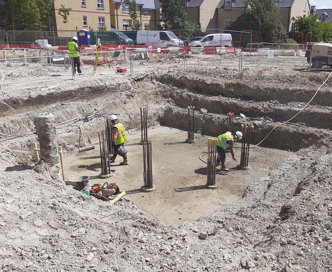
5. Foundations
The organisation, management and quality of foundations and substructures is arguably one of the most important work stages on any project.
All subsequent works rely on solid foundations; if we get this wrong, all else fails. This initial work activity is more significant than any other work stage for additional reasons.
It is the opportunity for us to ‘set out our stall’ and start as we mean to go on. Maintaining quality on a site that has set off on the right foot is much easier than trying to re-establish quality on a site without robust quality management control established from the outset.
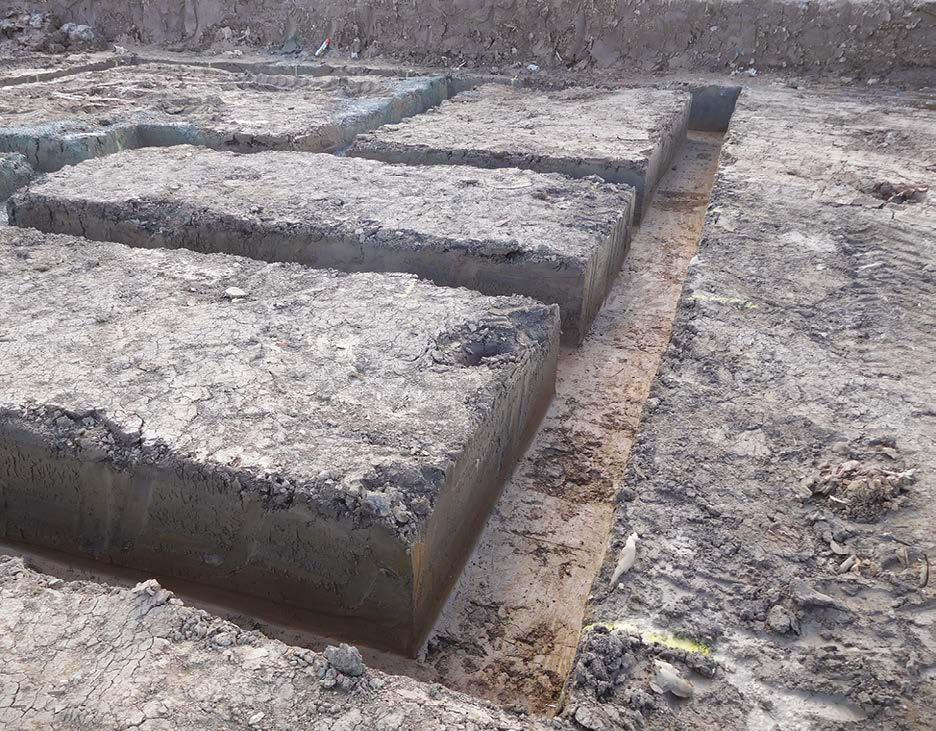
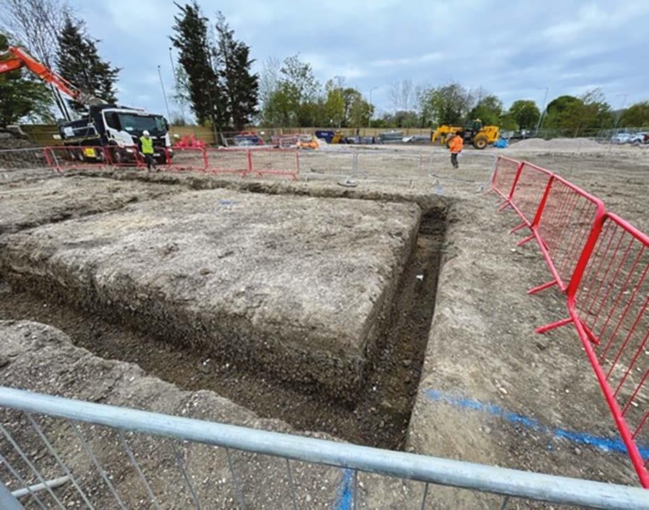
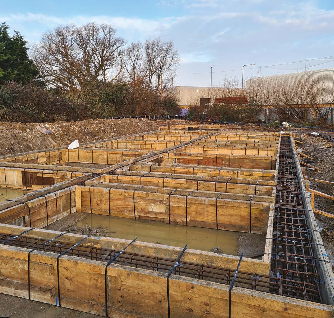
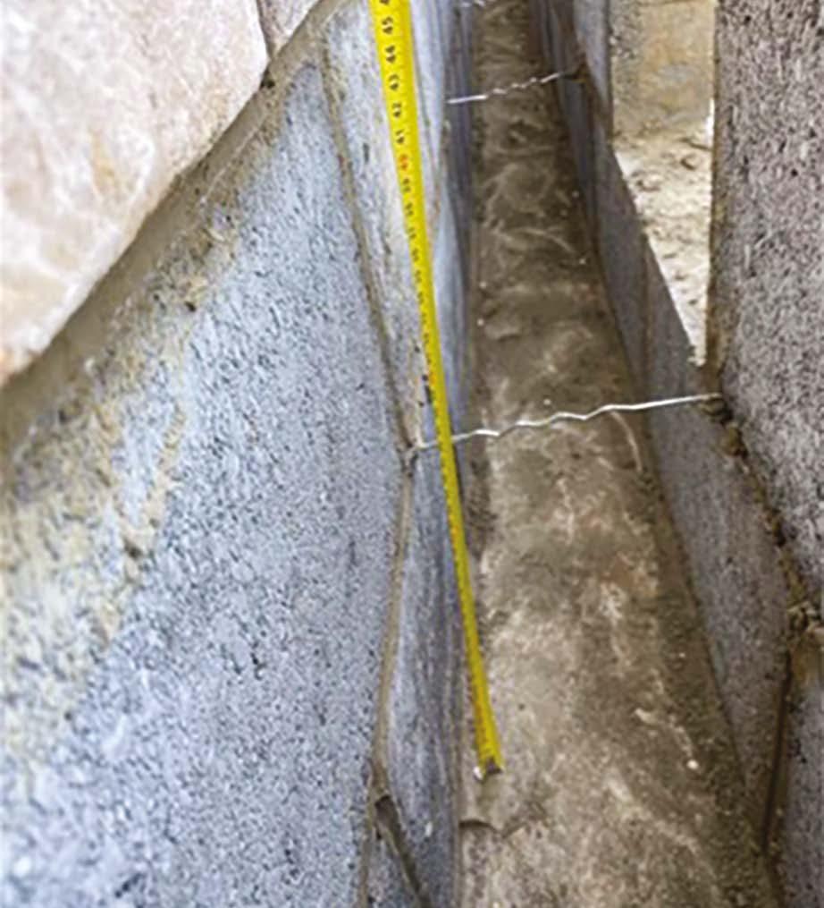
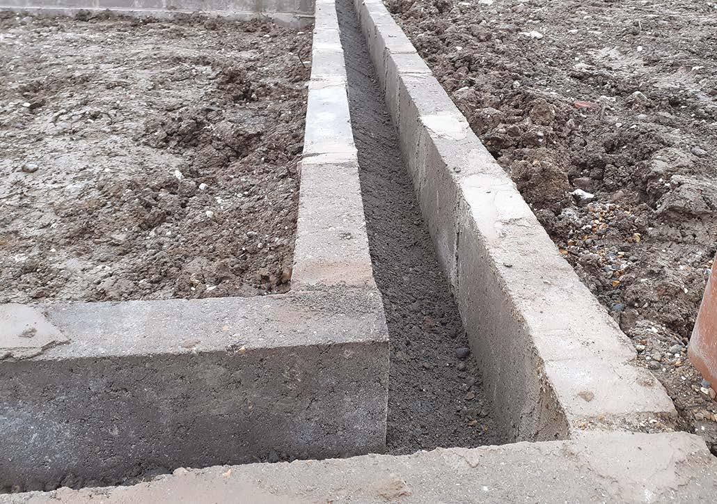
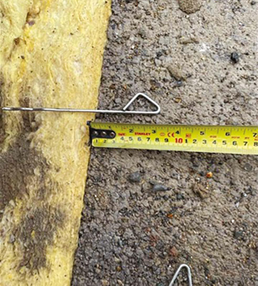
TRENCH / STRIP FOUNDATIONS
Formation
y Trench cut cleanly (appreciated that in these images they are formed in solid clay).
y Vertical trench sides.
y Clean and level trench bottom.
y Clean and level shoulders and working area around the trench / oversite.
y No loose material near top of trench that may fall into the excavation.
y Trenches straight and setting out checked.
y Trenches are free of standing water before concrete pouring.
y Finished concrete levels confirmed.
Foundation and substructure works are also challenging to manage as they are typically bespoke in design, with different design solutions adopted depending on the building design and ground conditions present on any particular site.
Additionally, the type of ground conditions and seasonal weather conditions can severely impact working conditions, which may impact quality. These should be considered when selecting the optimum design solution for a project as ‘buildability’ is an important aspect of quality. It is inappropriate to specify products that require ‘factory’ cleanliness in excavations in clay through winter months, as this may be impossible to achieve.
Where applicable, ensure that stepped strip foundations are formed as noted in Approved Document A, Diagram 21.
ELEVATION OF STEPPED FOUNDATION
Foundations should unite at each change in level
Approved Document A, Diagram 21
Minimum overlap L = twice height of step, or thickness of foundation or 300mm, whichever is greater.
S should not be greater than T
(For trench fill foundations, minimum overlap L = twice height of step, or 1m, whichever is greater)
Concreting
y Stop ends, construction (day) joints and steps in levels established, where applicable, with formwork and setting out checked.
y Reinforcement installed where designed, including at construction (day) joints to suit the engineer’s requirements.
y Concrete finished with a smooth float finish.
y Any concrete overspill removed from the surrounding oversite.
y Temporary weather sheeting is to be applied when heavy rain is expected before the initial set.
y Cold weather blankets are to be applied where required to protect from frost.
5. Foundations
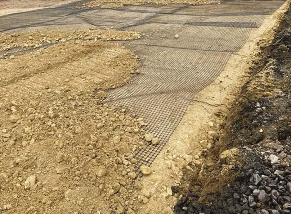
Piled Foundations
A temporary piling mat is to be installed in layers and compacted as per the temporary works engineer’s design.
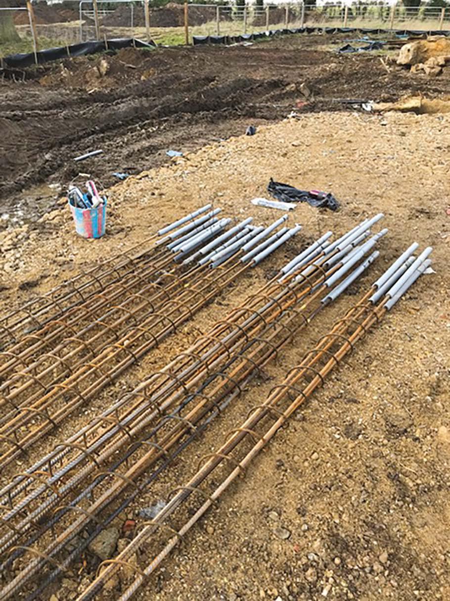
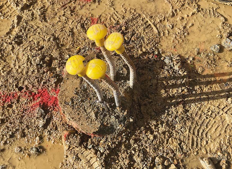
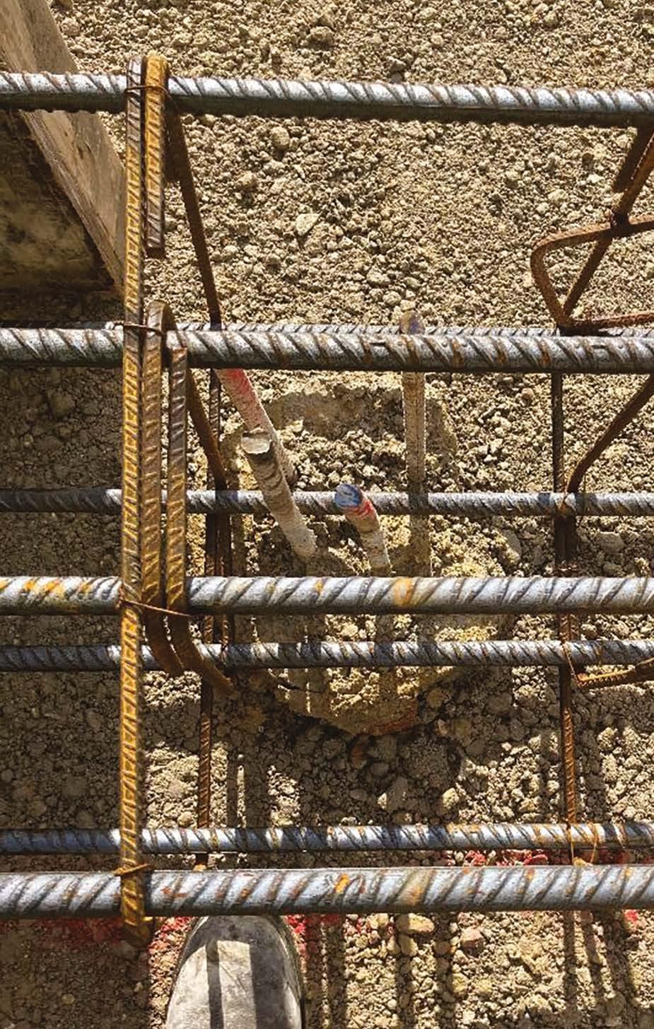
Pile reinforcement
y Cages are clean and free of contamination.
y Cages are rigidly tied and contain the specified reinforcement bars and links.
y Protective insulation is to be applied to permit correct reinforcement projection and lap.
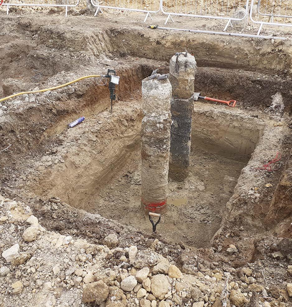
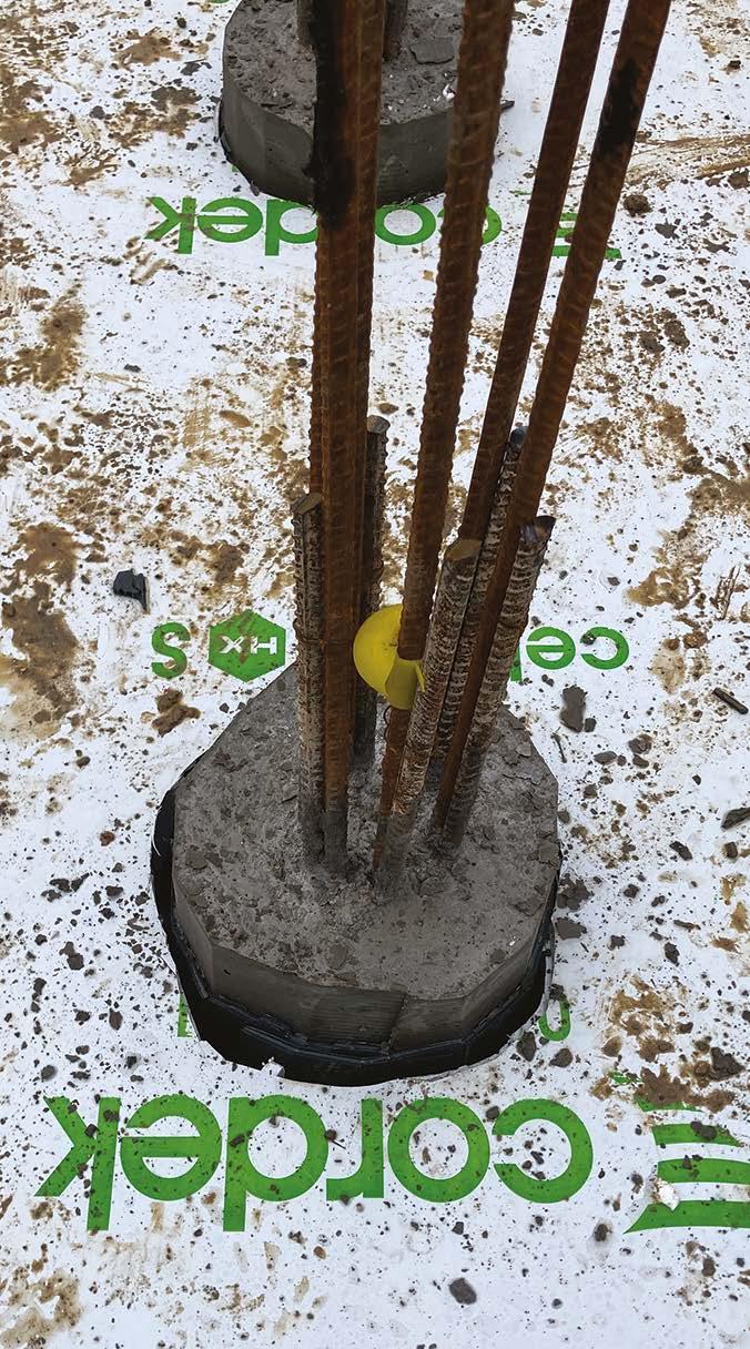
Pile Preparation
Piles are to be carefully cut down to the pile cap formation level, with close attention to ensure that the piles are not damaged. When cut, piles present a flat, level-bearing surface.
The pile is being carefully cut down, with debonding insulation over the reinforcement to the correct level.
Could this be better? Mushroom caps are missing and the excavation needs tidying.
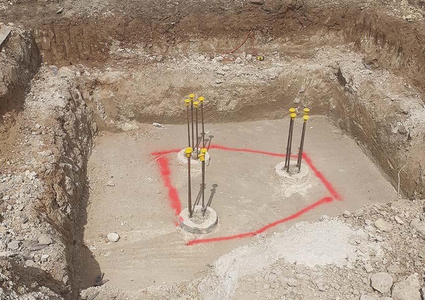
Piles have been carefully cut down to the required level. Temporary mushroom caps have been provided to the reinforcement. The formation level is clean and level.
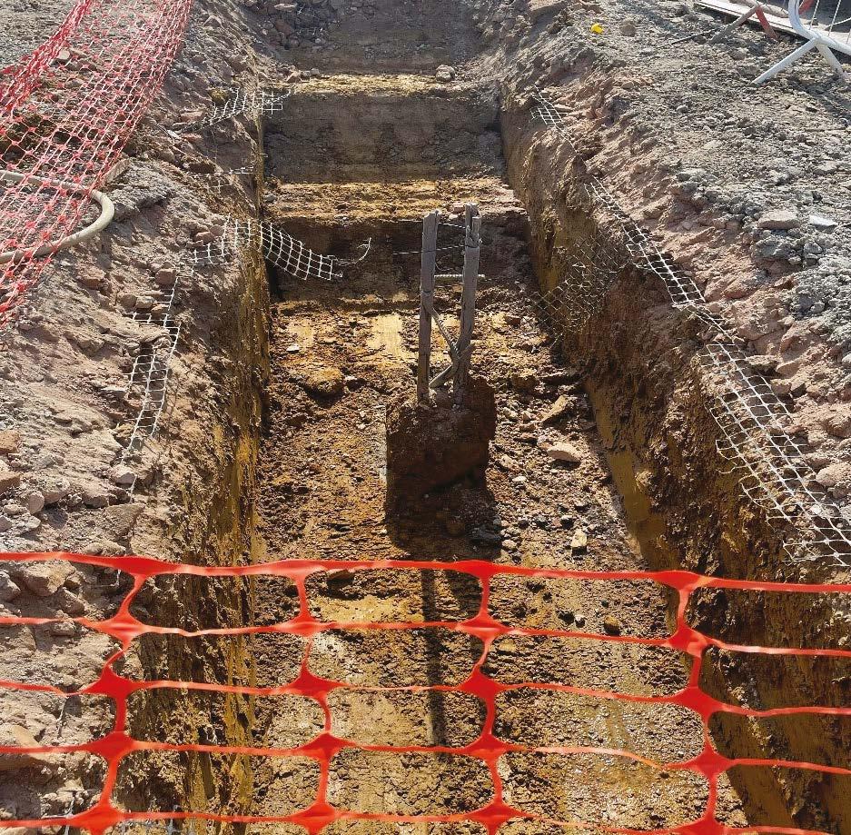
Issues to avoid – Refer to the structural engineer in all such cases.
The pile-bearing head is damaged, preventing a transfer of load to the pile across its full cross-sectional area.
Reinforcement is not placed symmetrically within the pile and pilebearing face is damaged.
The pile head is damaged and not set out correctly relative to the ground beam. The engineer will need consulting where piles are outside the stated setting out deviation.
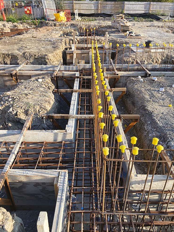
5. Foundations
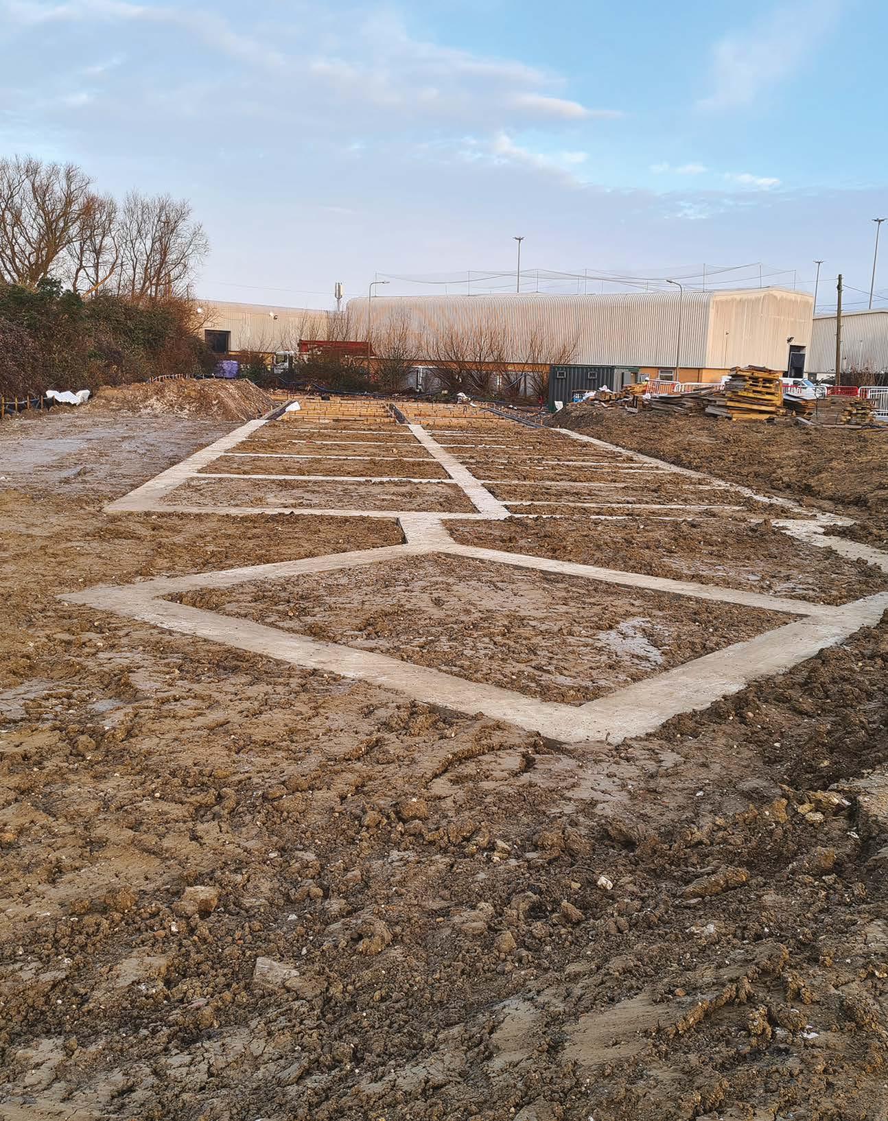
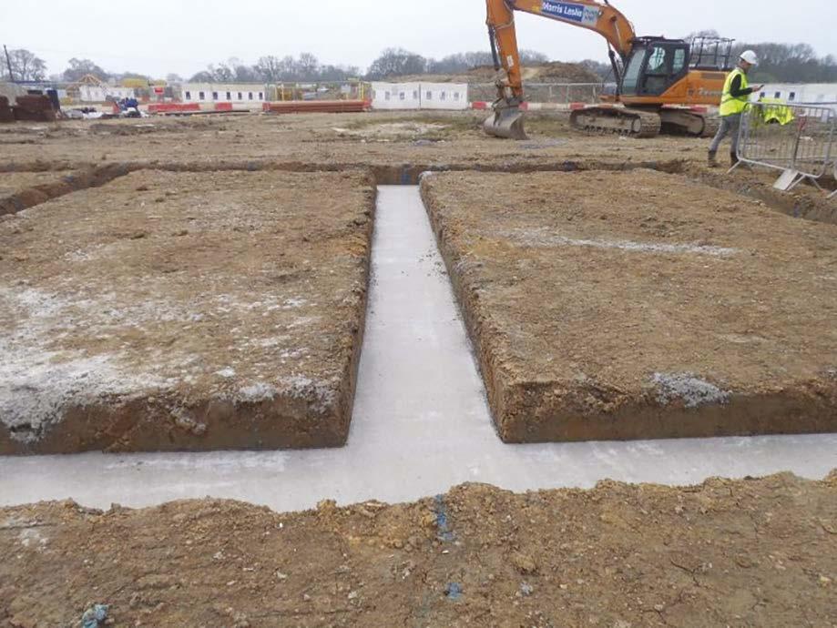
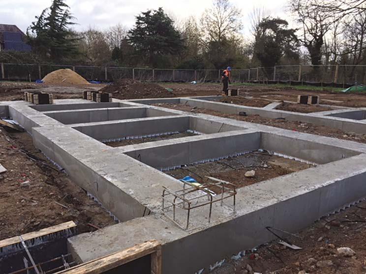
Ground Beams, Pile Caps and RC Ground-bearing slabs
Ensure that the formation excavation is level and clean and that the piles project above the formation level in accordance with the engineer’s design with a clean flat-topped pile head.
Beams and pile caps should be designed with vertical sides to avoid unintended loads being transferred to the ground. Where shutters are used, these must be straight and vertical.
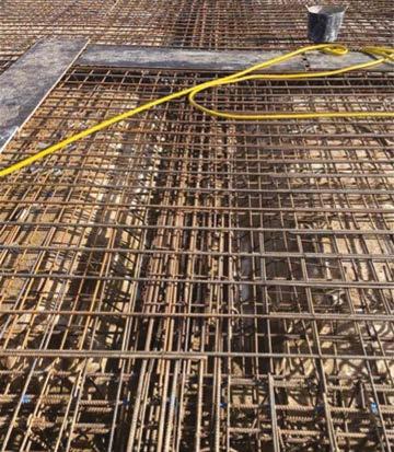
Checks should include:
y Reinforcement bars and mesh installed in accordance with design.
y Minimum laps achieved (typically 40d – check with Engineer).
y Cleanliness of reinforcement or flaky rust.
y Cleanliness of blinding/formation and shutters –remove debris and standing water.
y Reinforcement adequately tied to prevent deformation during the concreting operation.
y Adequate cover is provided using robust spacers.
y Provision of thermal blankets and/or heaters in cold weather.
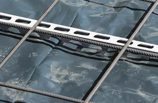
Anti-heave boards
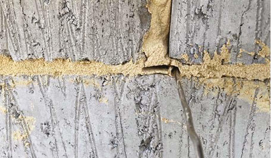
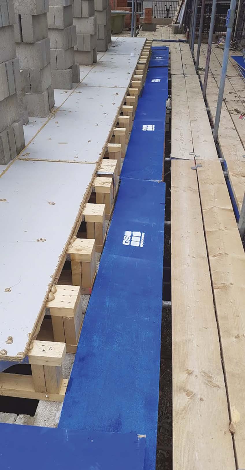
On many developments (generally containing expansive clay soils), compressible/void forming boards are installed to prevent ground heave damaging elements of the substructure. It is important that hard spots of grout or concrete are not created within these compressible or void-forming boards at board joints or where these boards are cut around pile heads etc. Joints and gaps must be sealed with suitable tape, expanding compressible foam, mastic or some other sealant. The method of sealing should be discussed and agreed with your engineer.
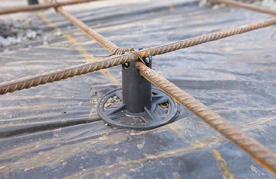
Spacers / Concrete Cover
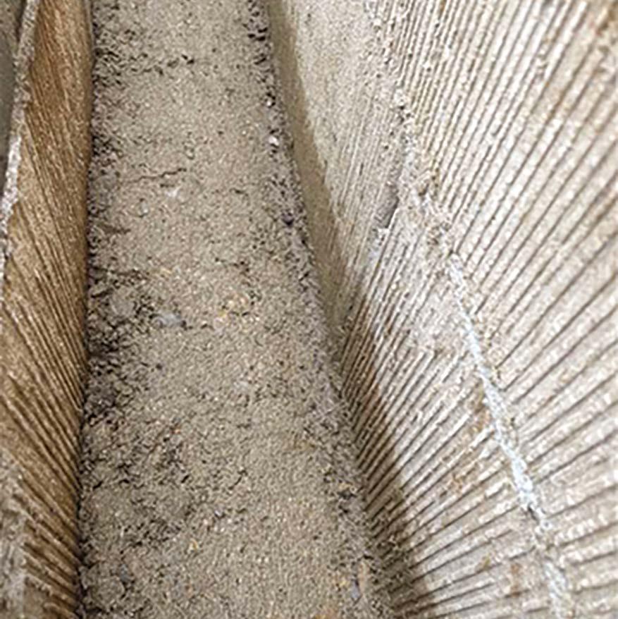
Void former has been cut around the pile head, but not sealed against grout loss causing a hard spot around the pile.
Spacers are required to ensure that the minimum concrete cover to reinforcement is achieved. These can be made from concrete (max 50mm x 50mm) or proprietary plastic tack spacers (max 350mm length to avoid restricting the aggregate flow within the spacer profile). Spacer must be staggered to prevent the formation of a plane of weakness in the concrete.
Spacers staggered to avoid planes of weakness
Technical images source: nhbc-standards.co.uk
Joints between void-former boards sealed with tape.
Spacer layout
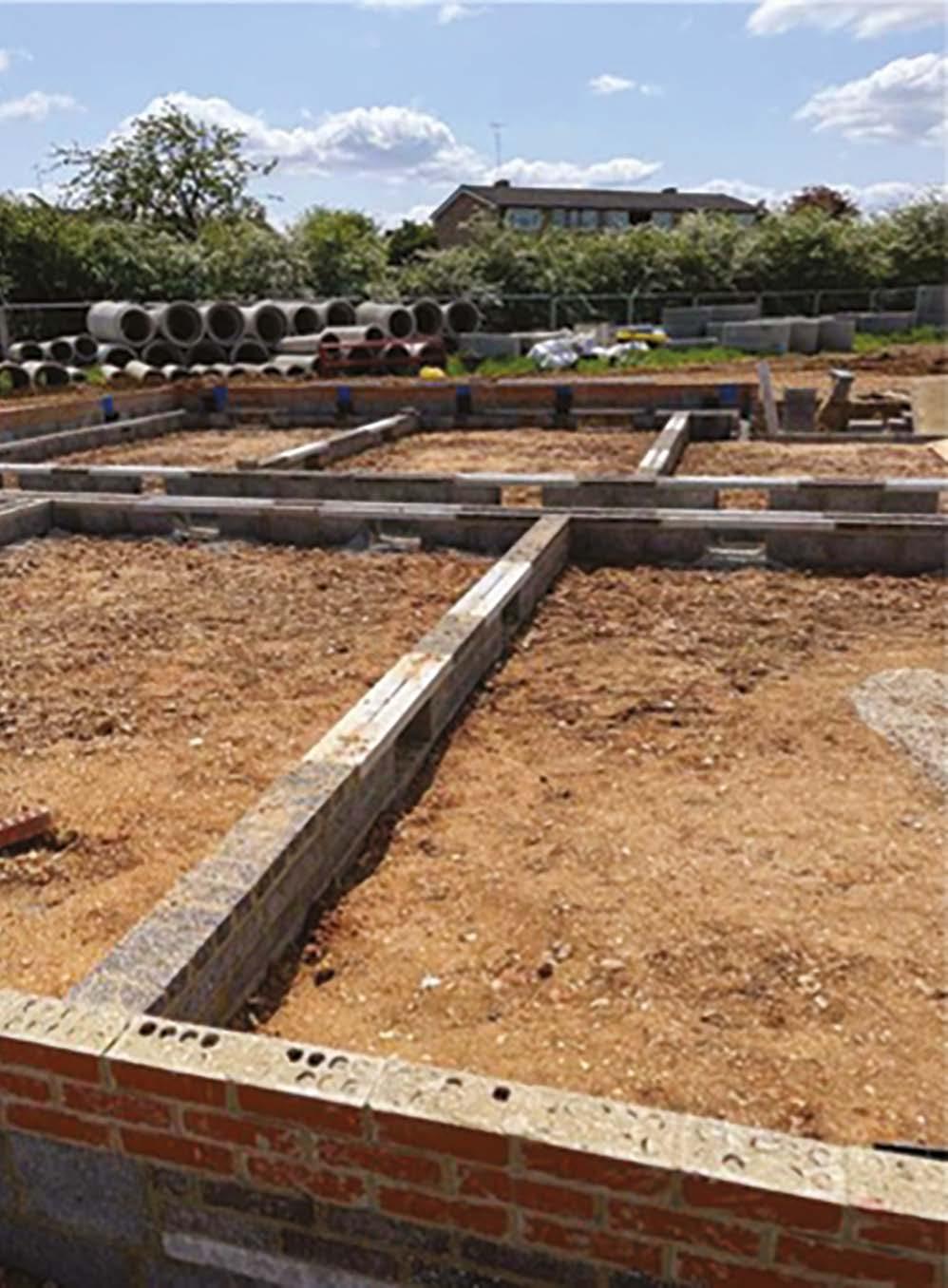
6. Substructures
Every effort must be made to provide a good working environment for substructure operations, including clean level ground with safe access.
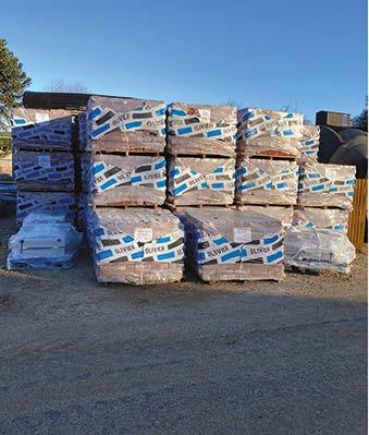
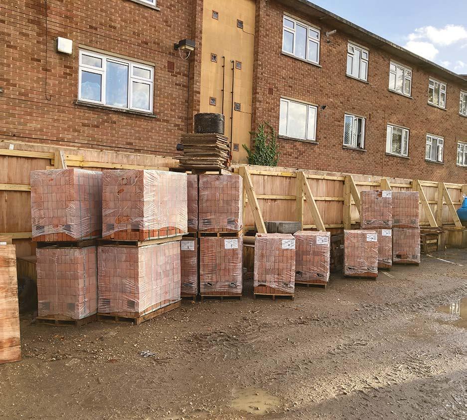
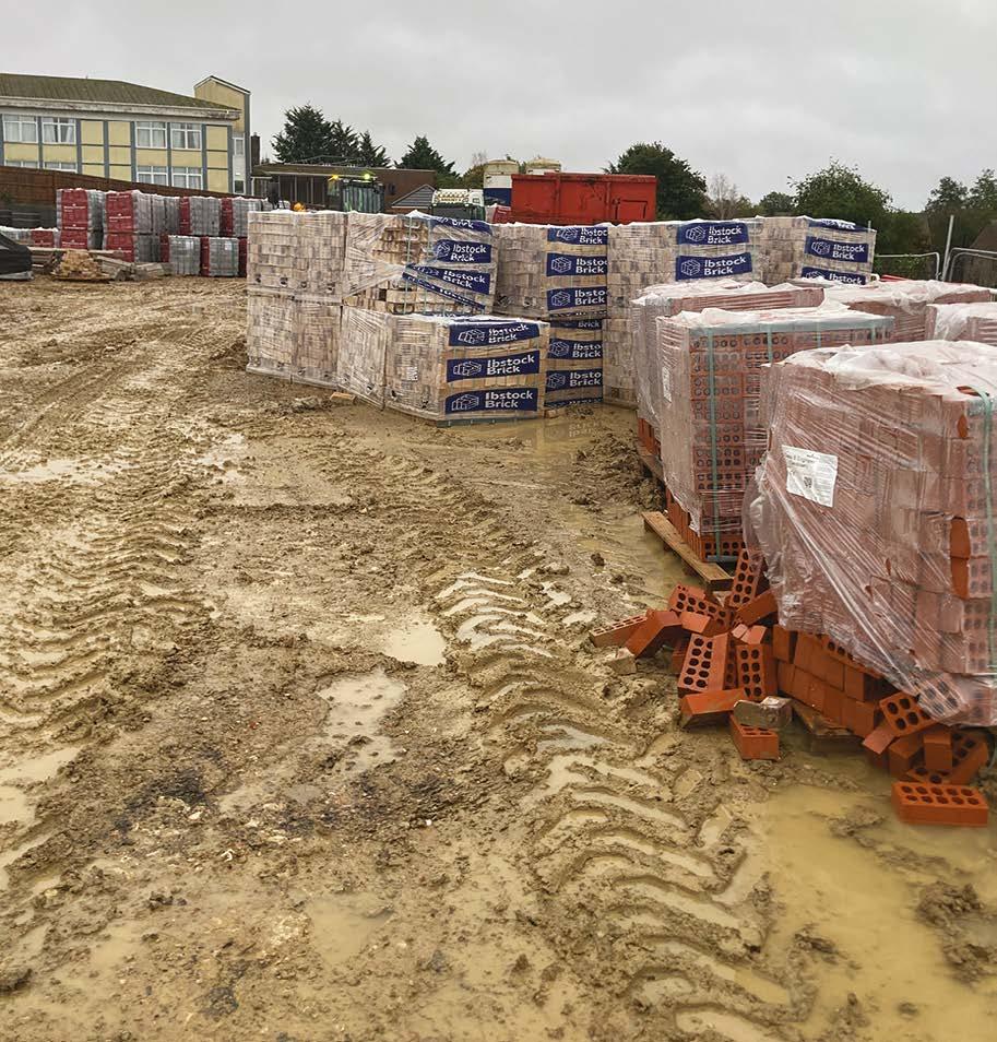
Bricks and blocks should be protected from inclement weather and stored on pallets up off the ground.
Mortar used below DPC must be as specified by the engineer. This may include sulphate resisting cement of other properties relevant to the prevailing ground conditions.
The concrete fill should slope externally and be free from debris, mortar or rubbish.
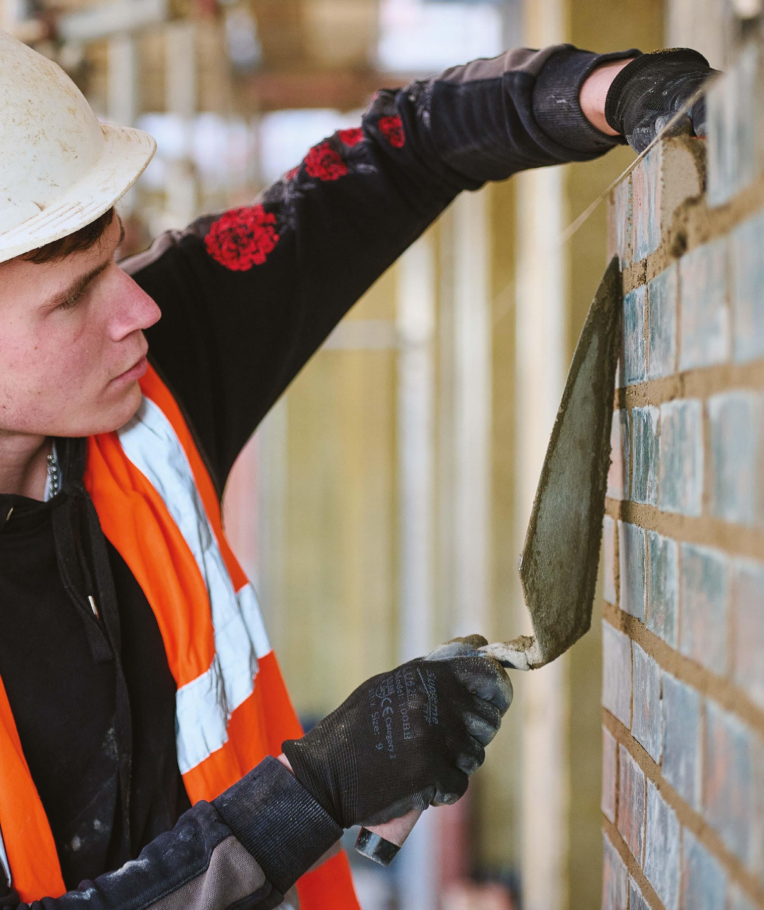
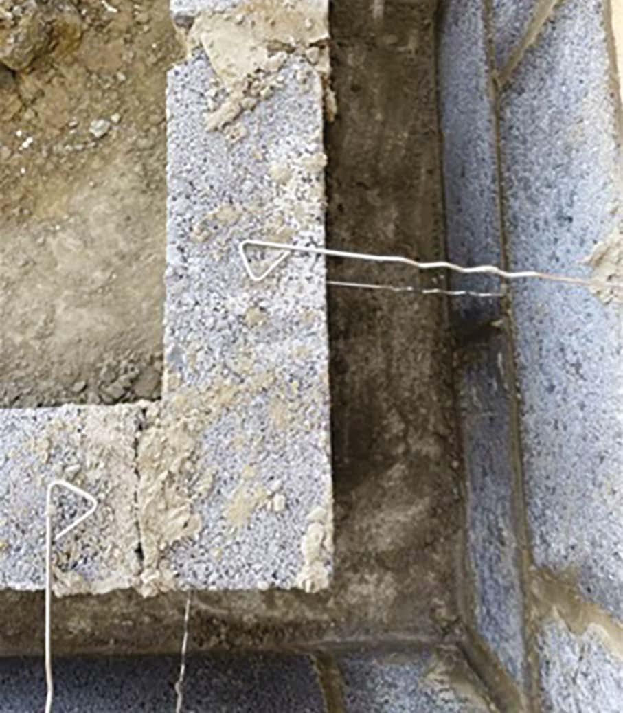
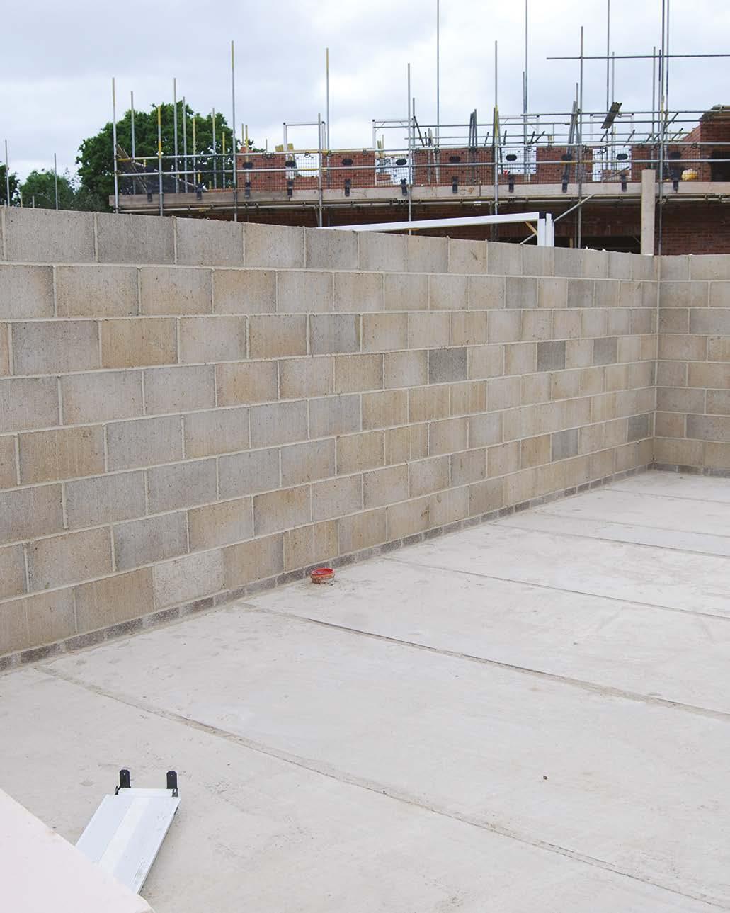
Substructure masonry
This should be carefully set out and checked. Setting out errors at this point will impact all further works.
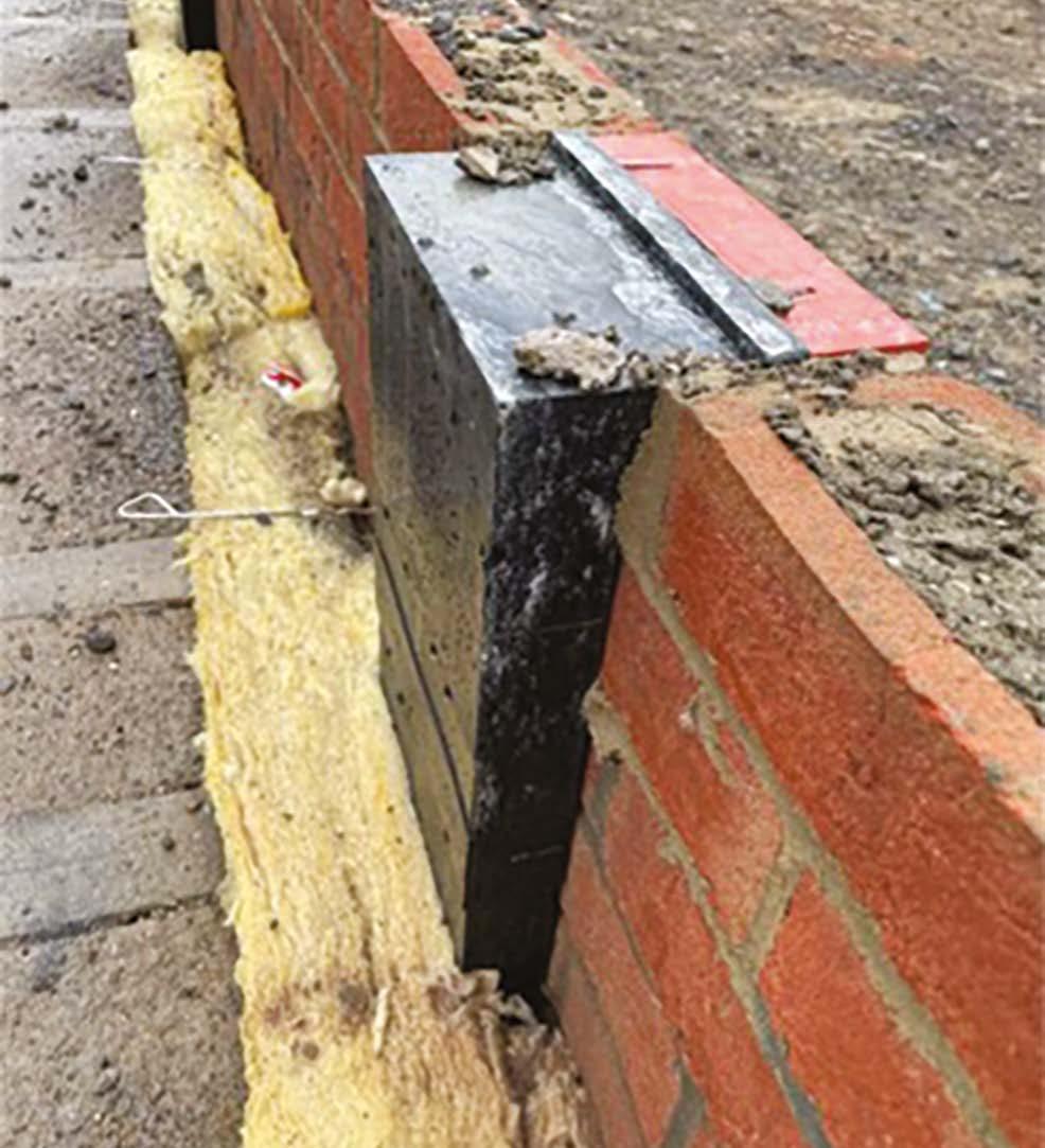
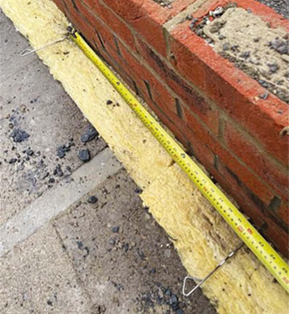
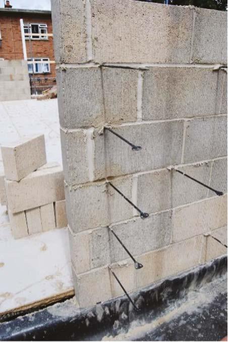
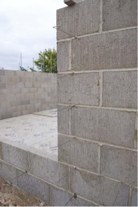
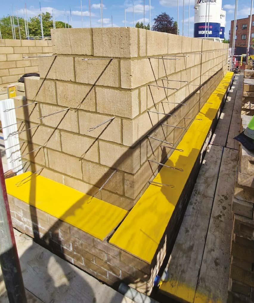
Substructure masonry should be constructed to the same standard as superstructure work, with consistent joints, fully filled and brick tie spaces at 900mm horizontally and 450mm vertically in a diamond pattern.
Where cavity walls are constructed below ground, these are to be concrete filled no higher than 225mm from DPC level.
Wall ties should be installed with a minimum of 50mm embedment.
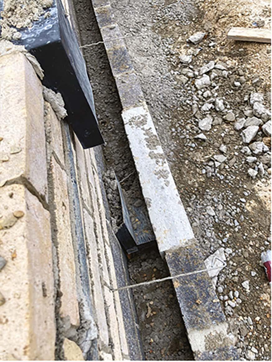
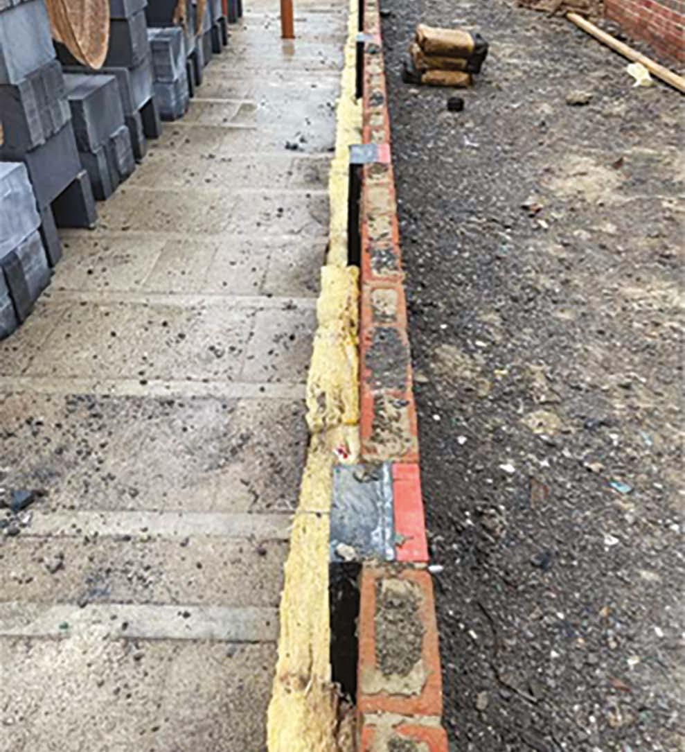
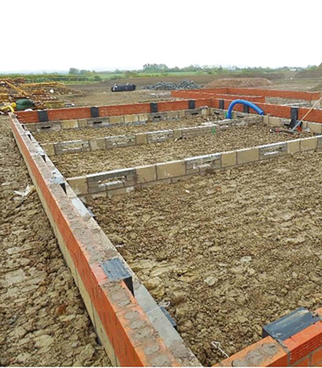
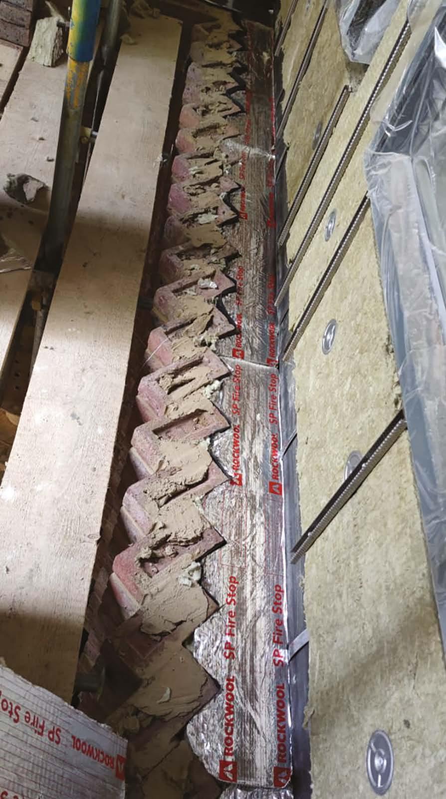
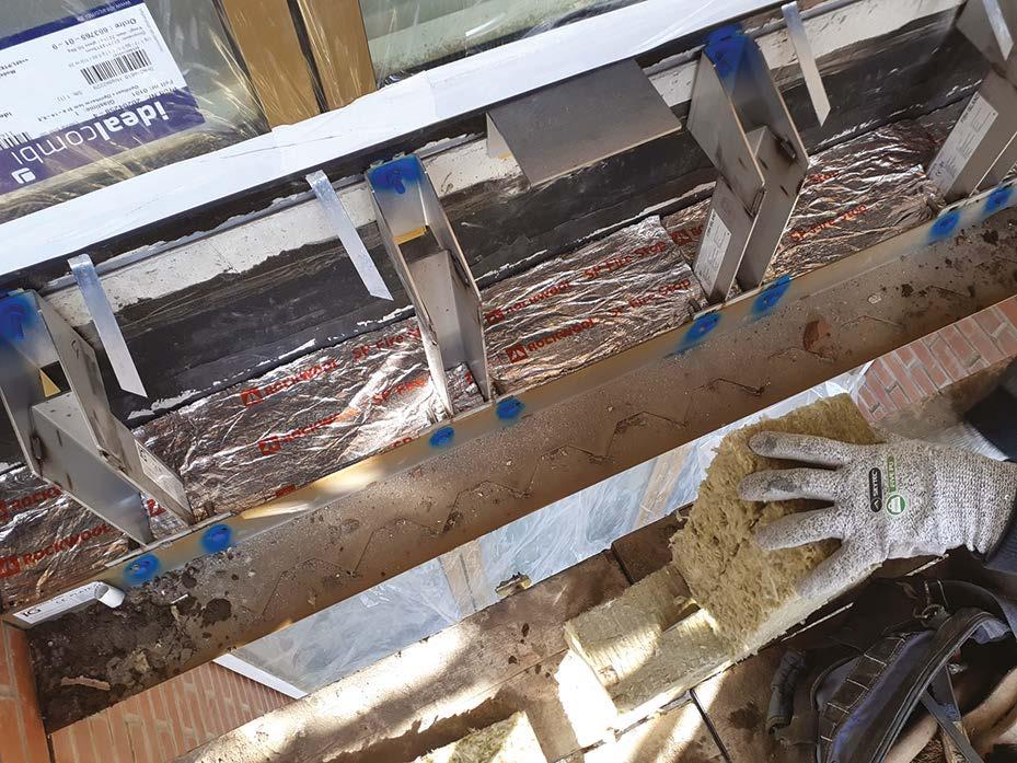
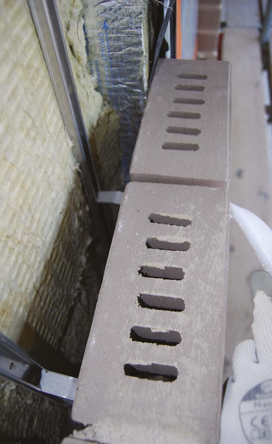
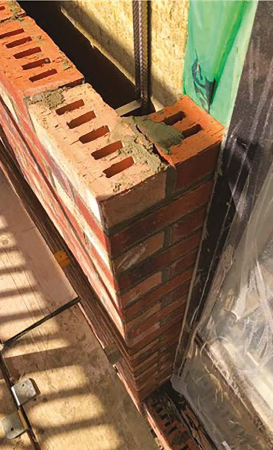
Cavity wall insulation must be certified for use below DPC.
Where installed, this should be tight fitting, with no air gaps present. The insulation should be installed in accordance with the manufacturer’s instructions.
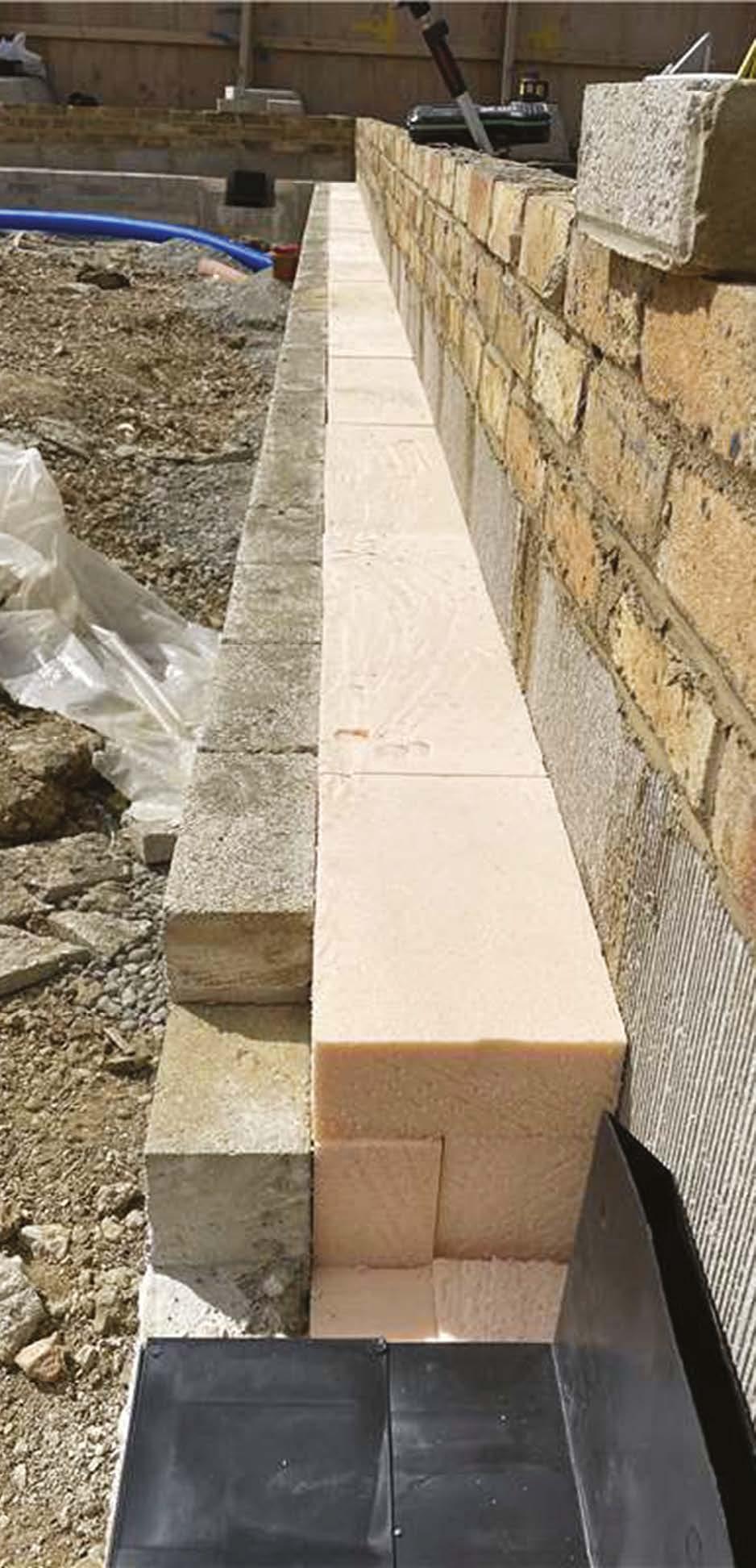
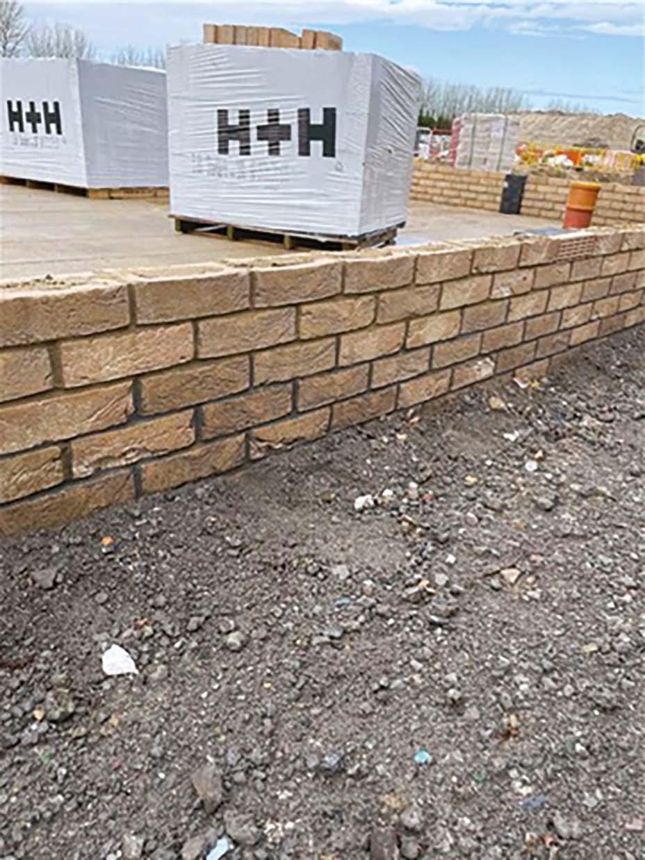
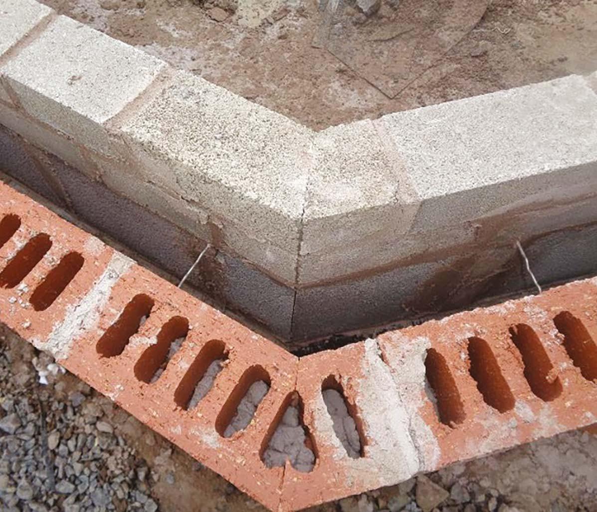
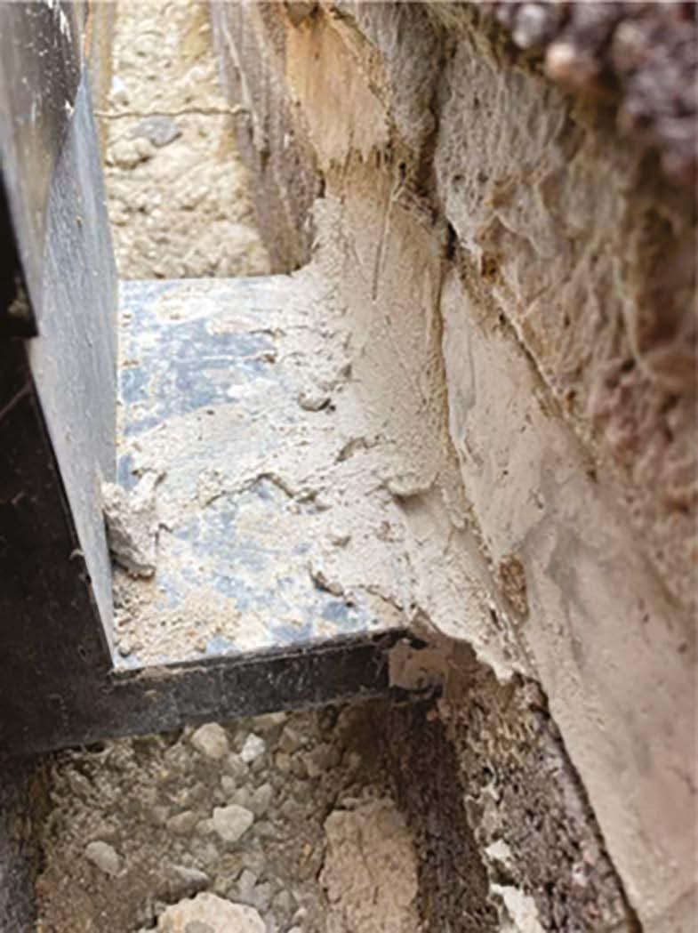
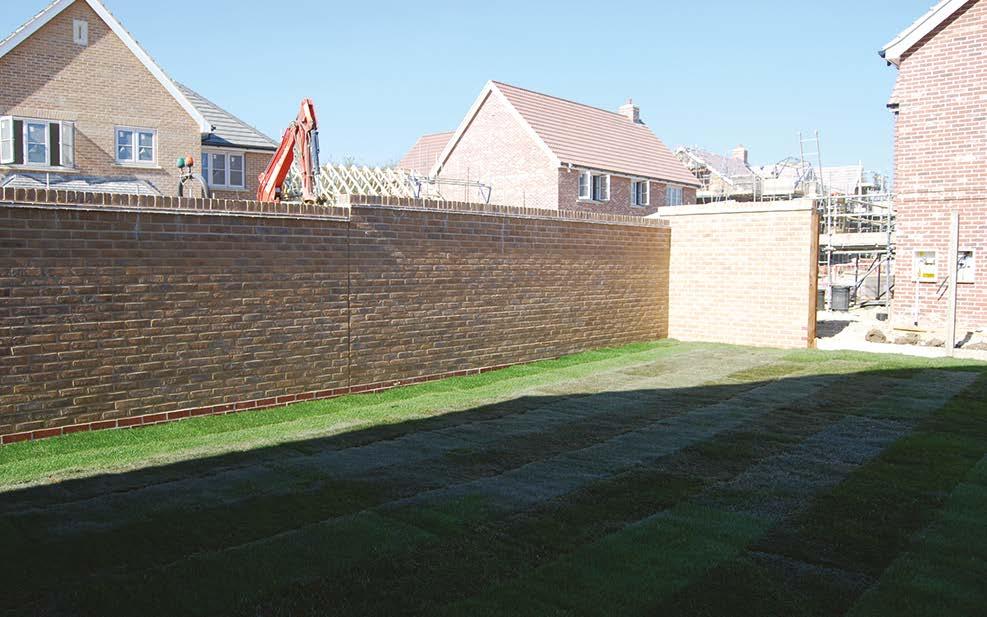
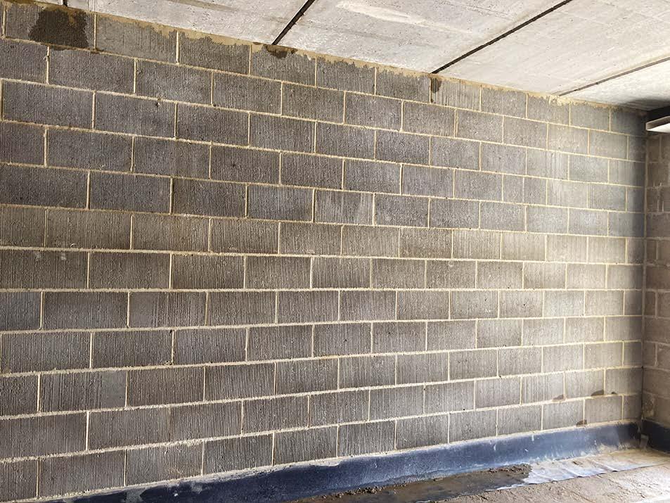
In this image, care has been taken to ensure that the installation is close fitting with neat masonry. Joints, including those to the cavity face, have been ironed and finished to ensure that these are fully filled.
A level working area and high-quality workmanship have resulted in excellent quality 'splash course' brickwork.
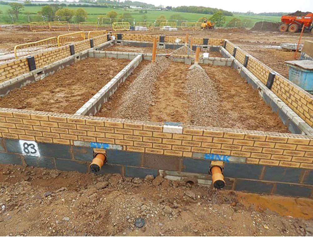
6. Substructures
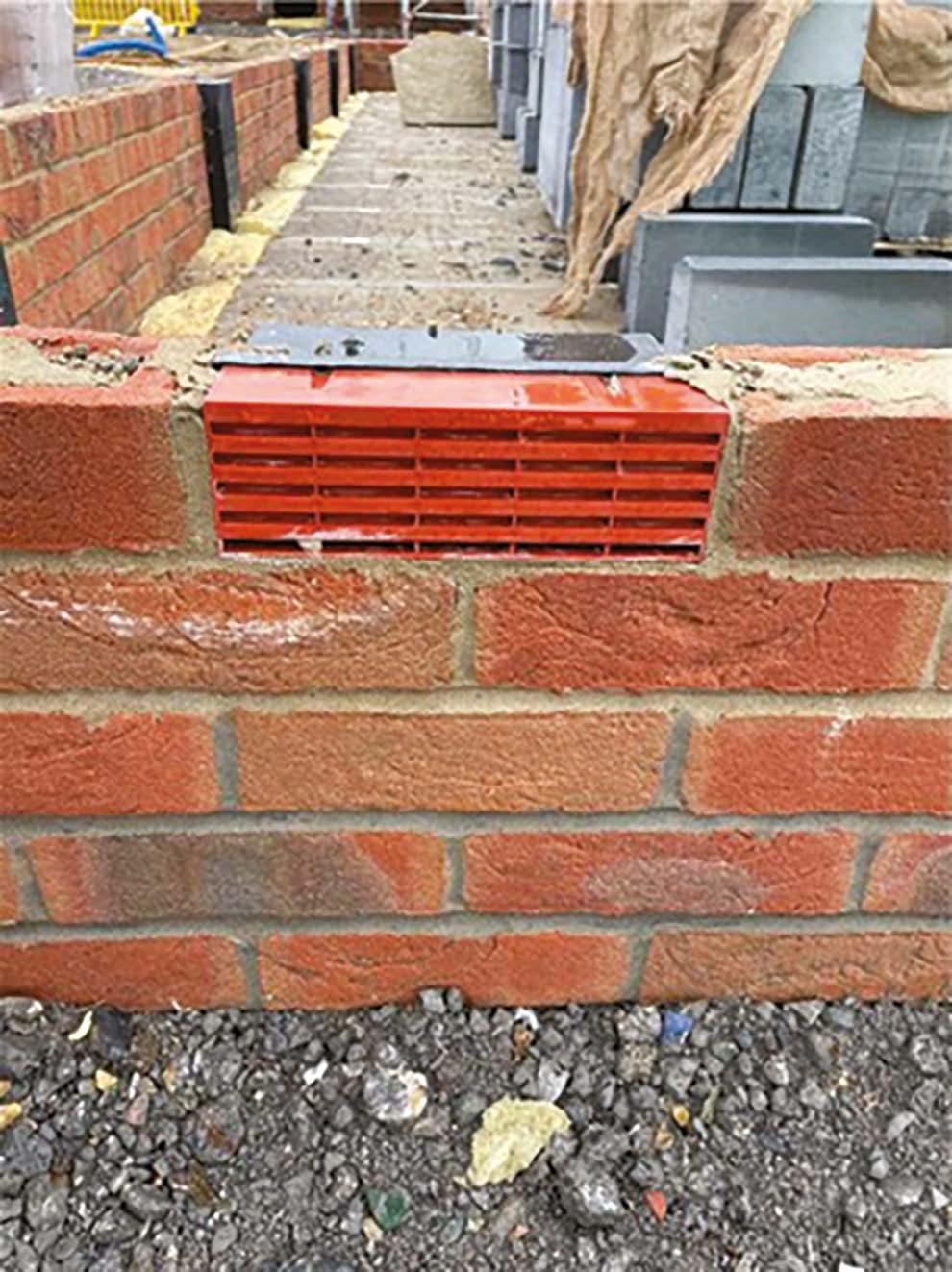
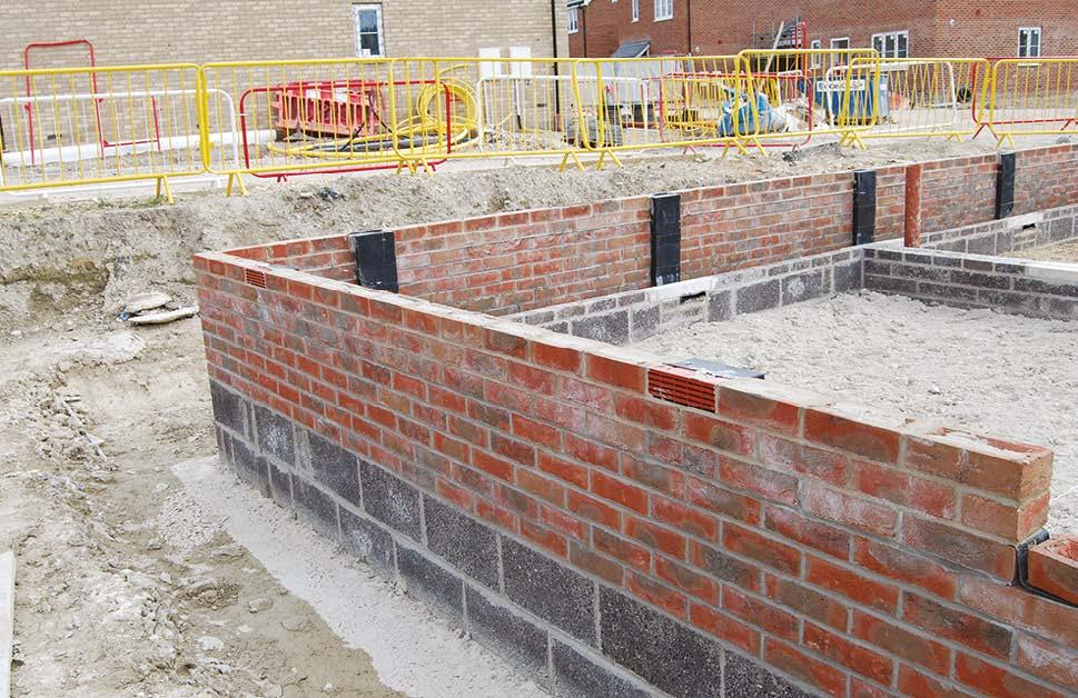
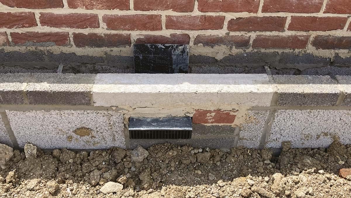
Care has been taken to align this airbrick neatly within the bond of the wall.
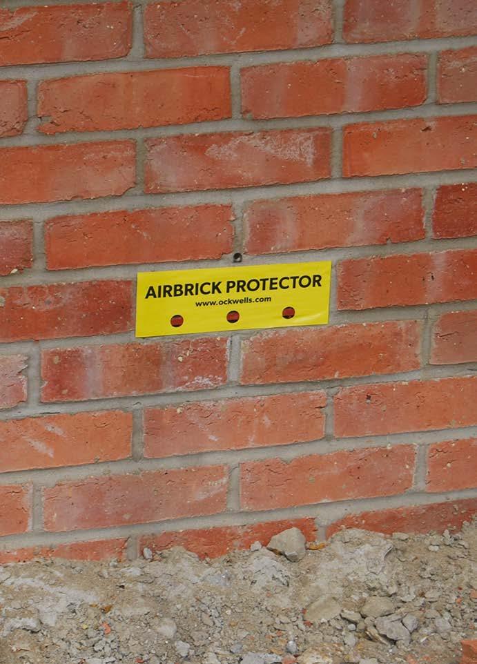
Air brick protection is a good way to keep airbricks clean and free from mortar and minor damage.
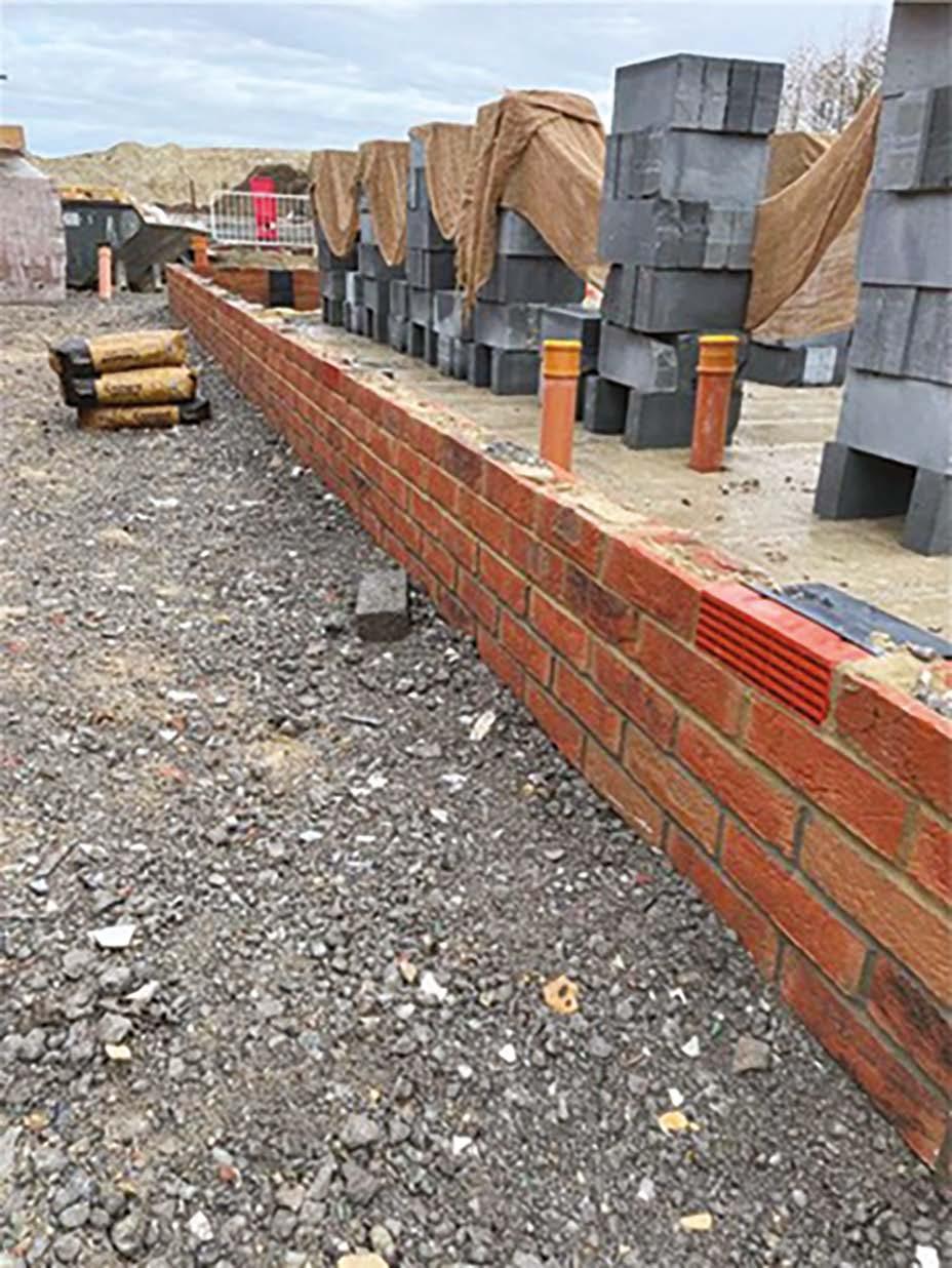
Very neat substructure masonry has been achieved to this bay window.
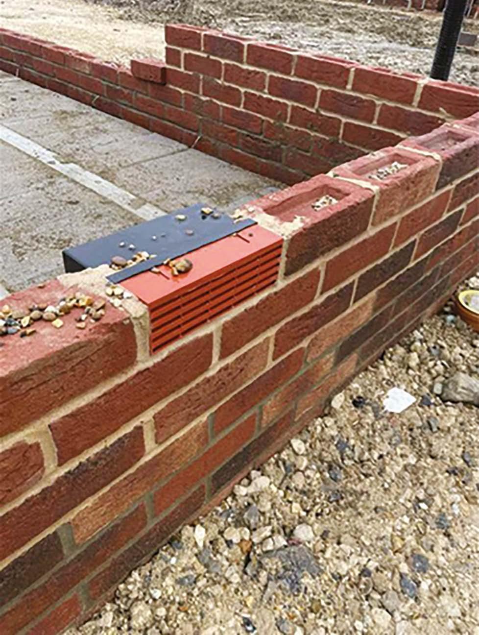
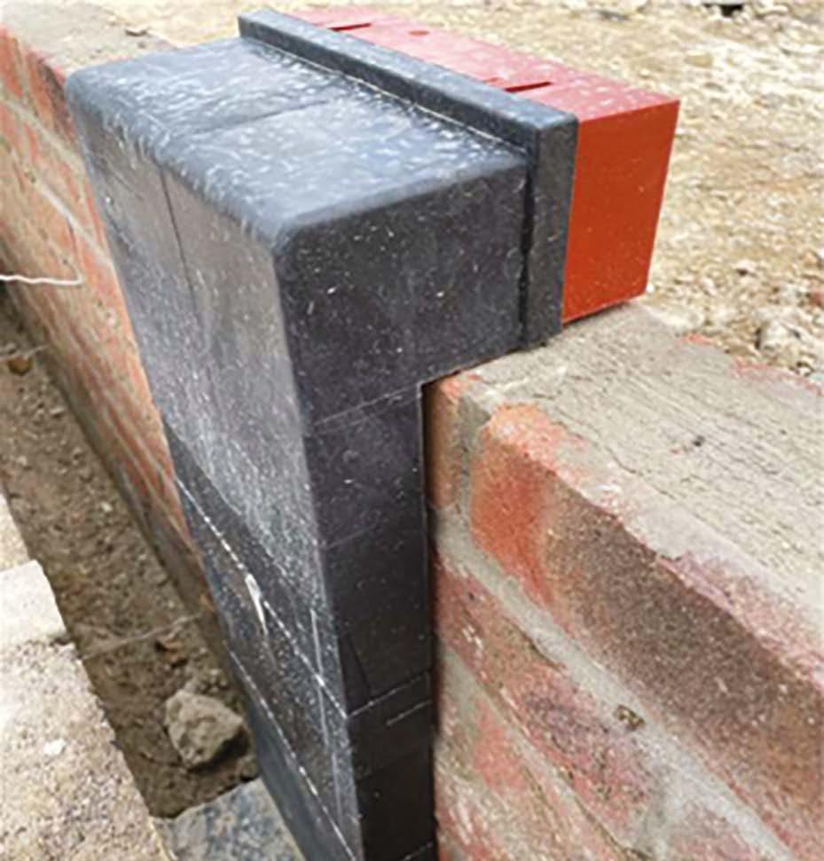
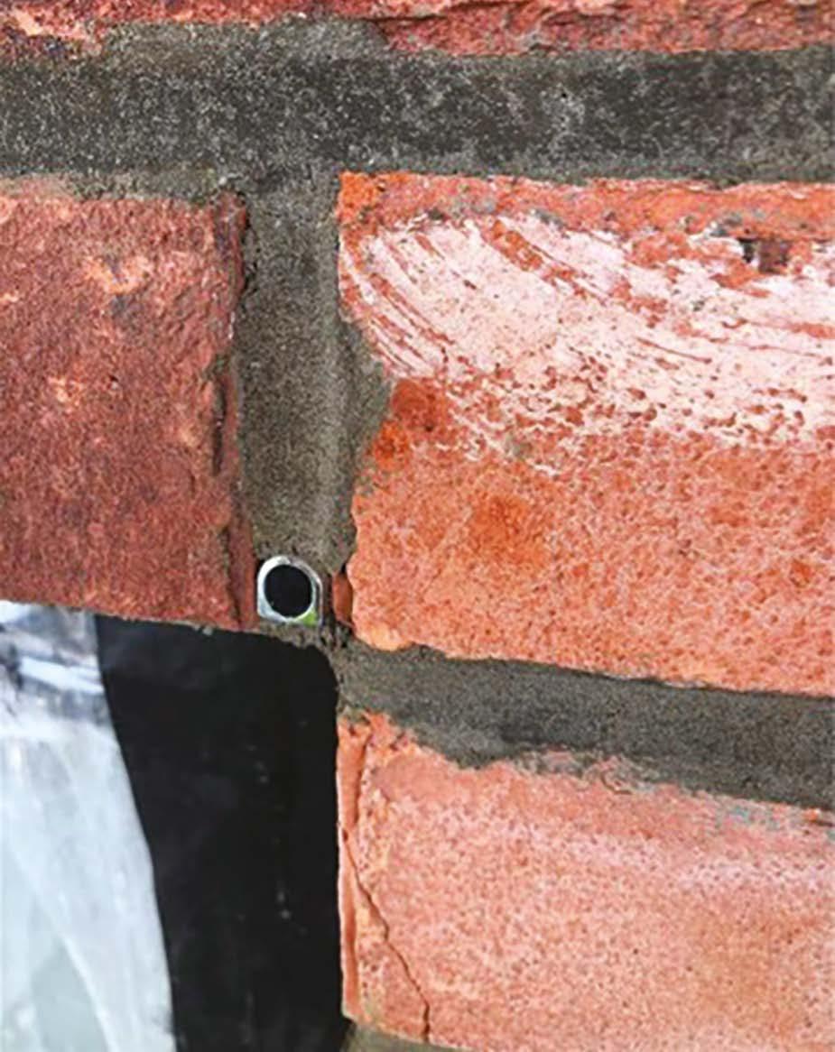
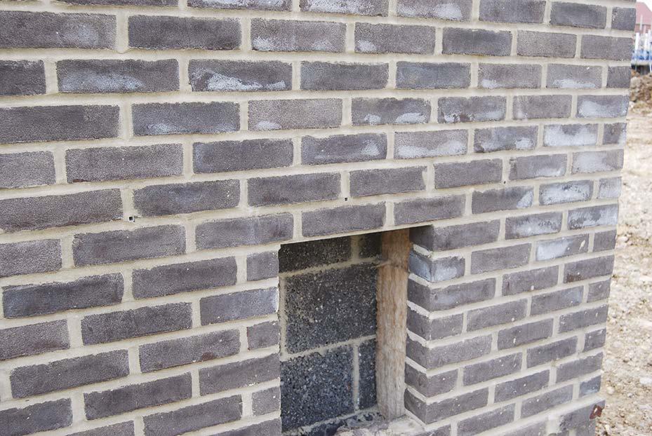
An exemplary installation with the telescopic air vent installed correctly to the outer leaf of masonry. The cavity insulation will then maintain a warm envelope to the home.
The cavity is spotless.
The telescopic vent is located within an oversized hole (with lintel above) to enable the vent to align with the brick bond. This hole has been subsequently fully sealed up to prevent vermin and unwanted venting of the cavity.
6. Substructures
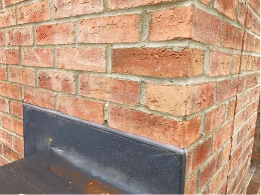
Issues with telescopic vents
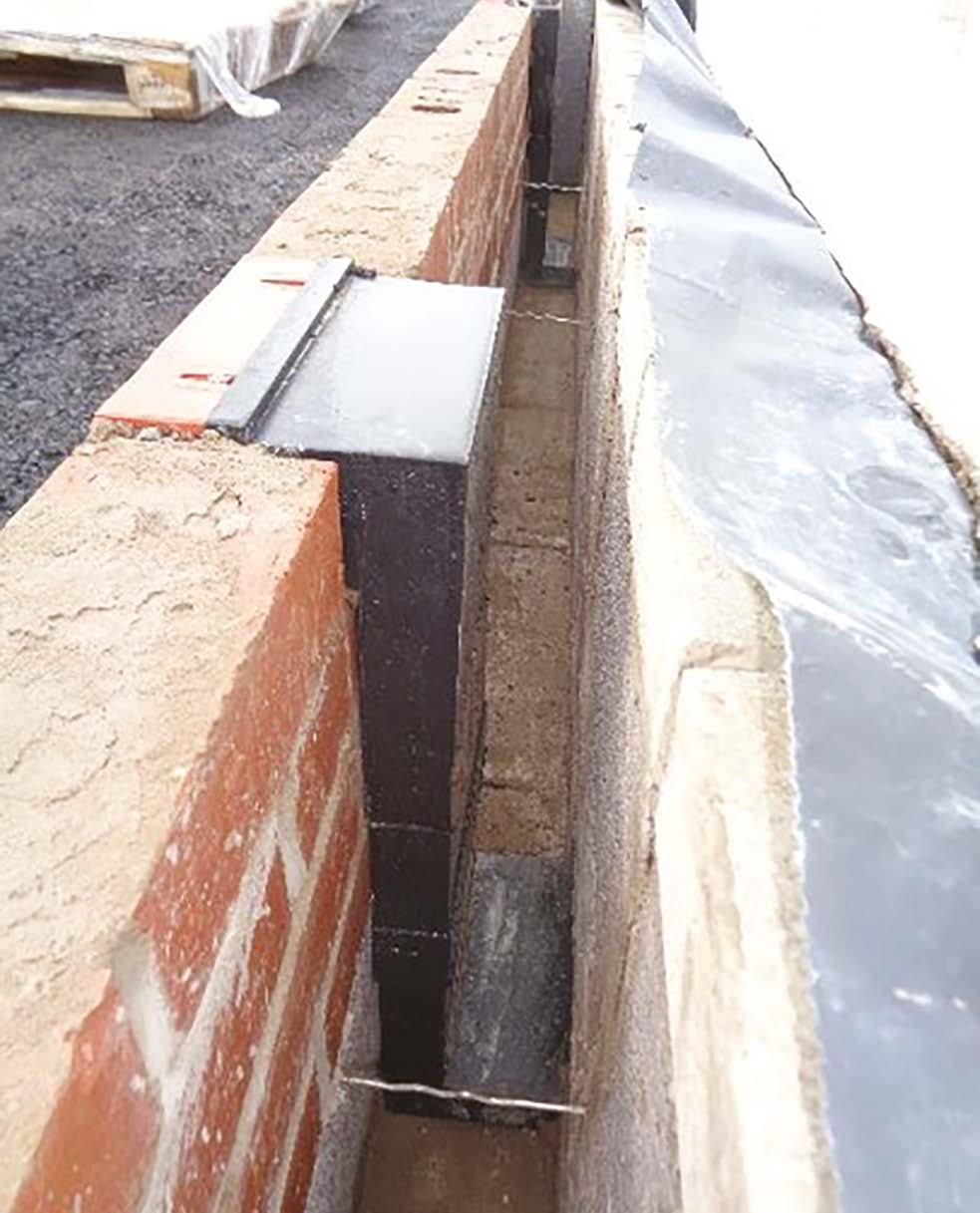
In this image, all looks neat, but the telescopic vents have been incorrectly installed to the inner leaf of the wall, rather than the correct outer leaf. As installed, the cold air within the vents would cause a cold bridge within the home.
In this example, the telescopic vent was permitted to be filled with lean mix concrete. This will have to be fully cleaned before assembly, with all debris removed.
Here we see the careful installation of fibreglass insulation, including the correctly installed insulation to the warm/internal side of the telescopes.
Insulation is tightly abutted, and wall ties are correctly installed at a maximum 900mm centred horizontally and a minimum 50mm embedment.
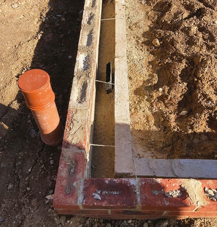
Neat and tidy substructure walls with lintels installed for services, drainage and air across flow.
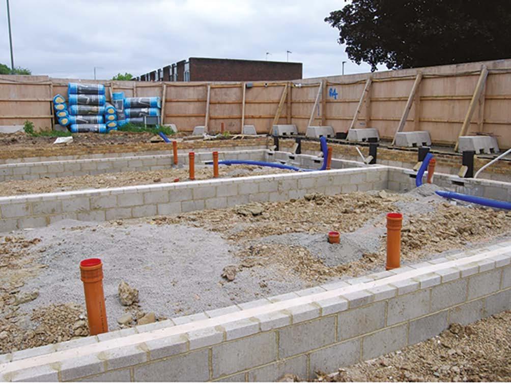
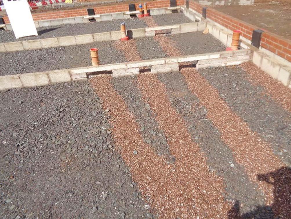
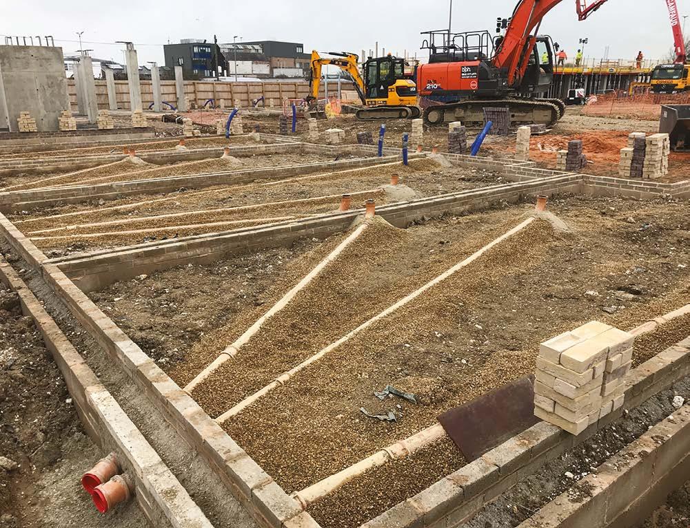
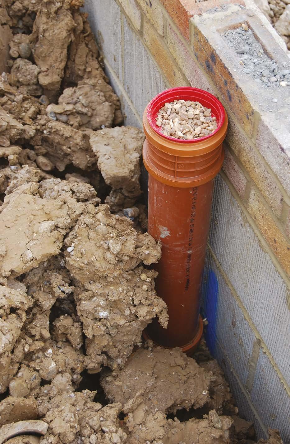
7. Drainage
Drainage should be:
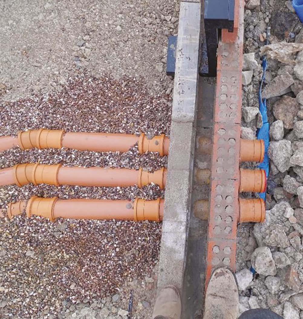
y straight with a minimum of 1:80 fall (12.5 mm per metre) or 1:40 where flow rates are less than 1L/second.
y fully supported with a minimum of 100mm pea shingle.
y rest bends supported by concrete.
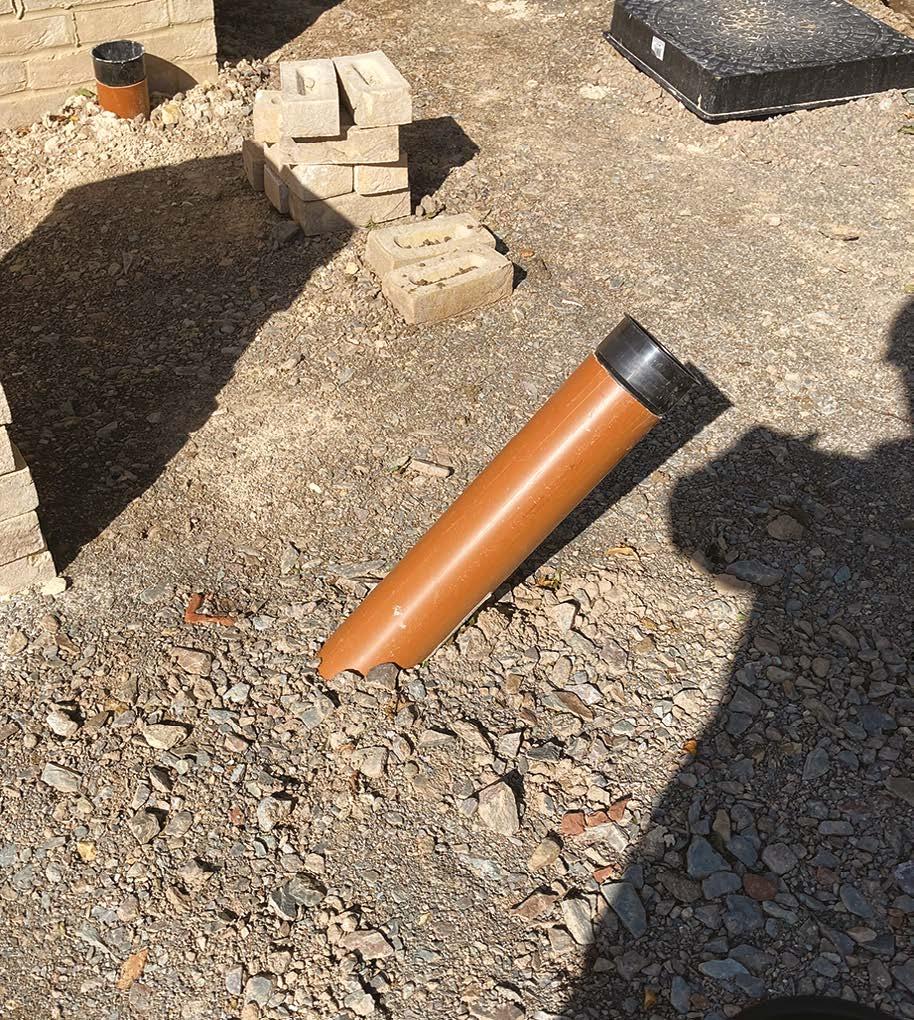
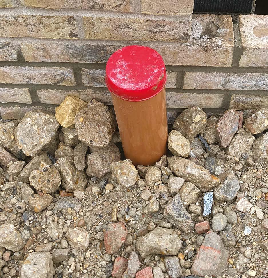
y temporary caps are inserted to prevent debris and contamination of the drainage system.
Please note that additional supports or joints may be required to suit ground conditions and movement.
Where ground movement is anticipated an extended rest bend should be specified to ensure that the below-ground drainage and aboveground drainage do not part company or crush due to ground settlement or heave.
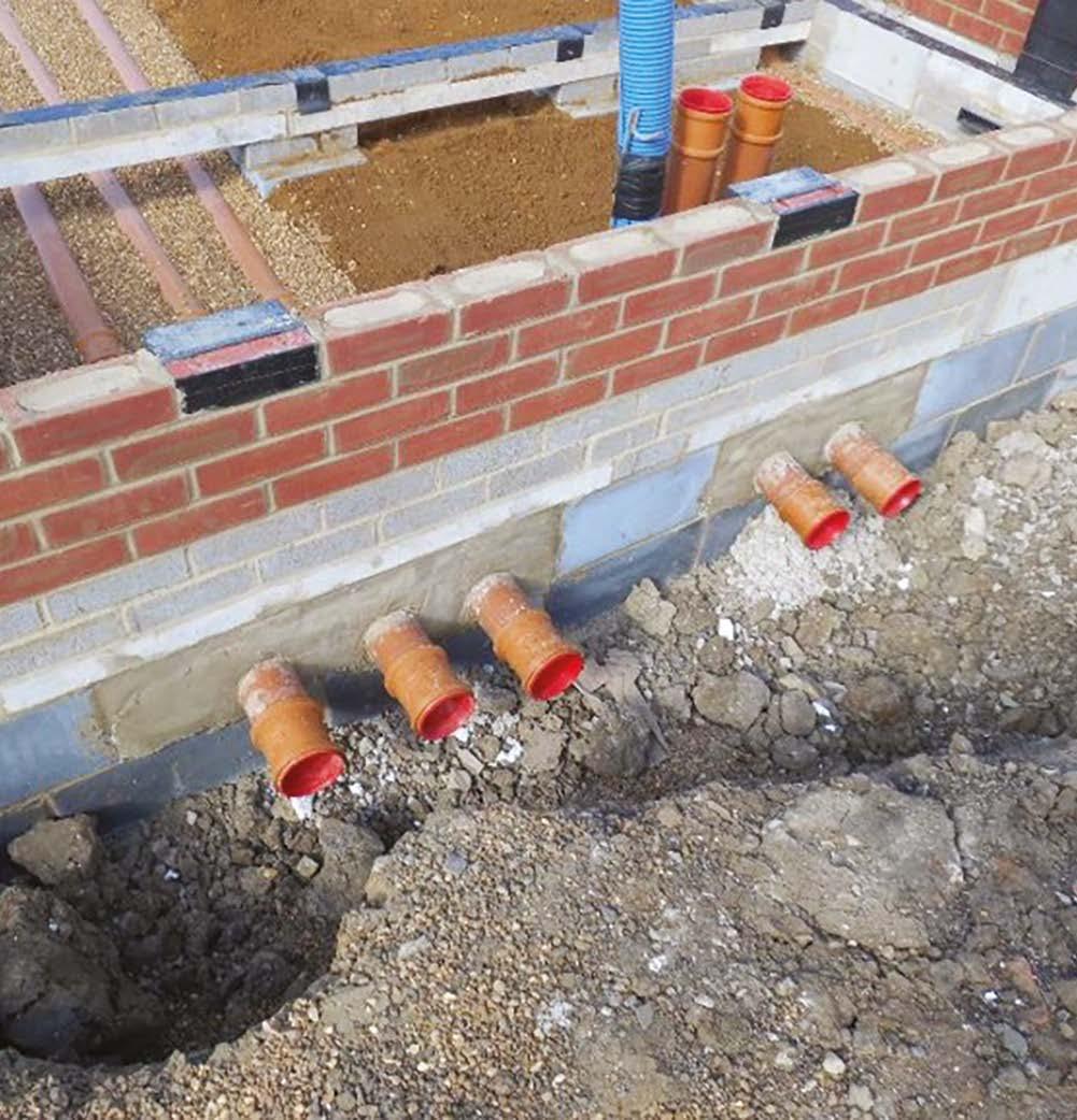
Where drains pass through substructure walls, one of the following two solutions must be adopted.
600mm max.
150mm max.
150mm max.
600mm max.
Examples of where rockers have been correctly installed.
Pipes passing through a lintelled opening
Minimum 50mm space around pipe
Opening masked on both sides
Pipe passing through lintelled opening
Pipe bedded in walls
Flexible joint
Flexible joint
7. Drainage
Vertical fill material should ideally be pea shingle however excavated material may be used providing it:
y Contains stones no larger than 40mm.
y Clay lumps no larger than 100mm.
y No organic or frozen material.
Unacceptable, as it contains stones larger than 40mm
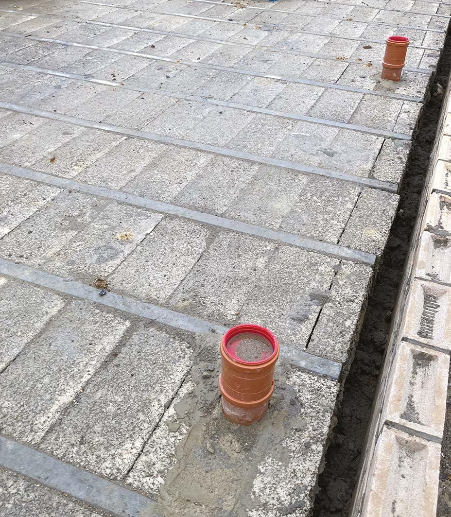
Drainage neatly installed with temporary caps fitted.
Unacceptable, as Clay lumps are larger than 100mm
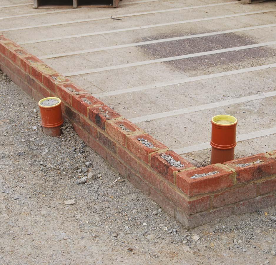
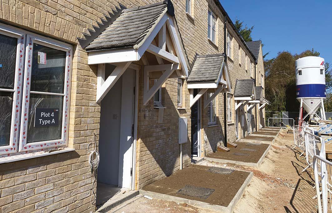
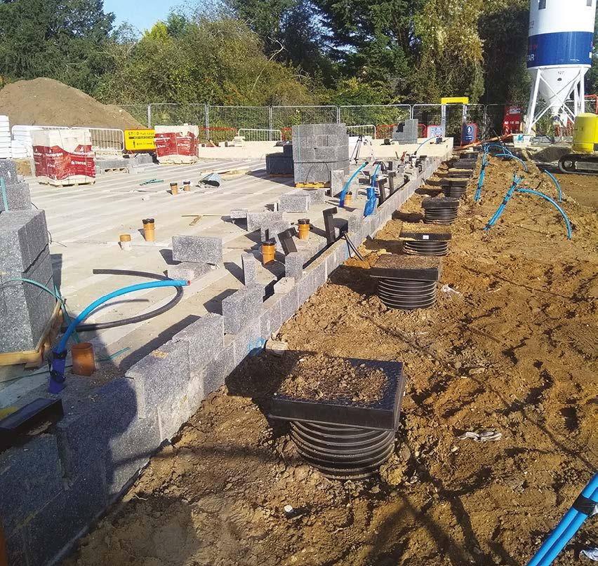
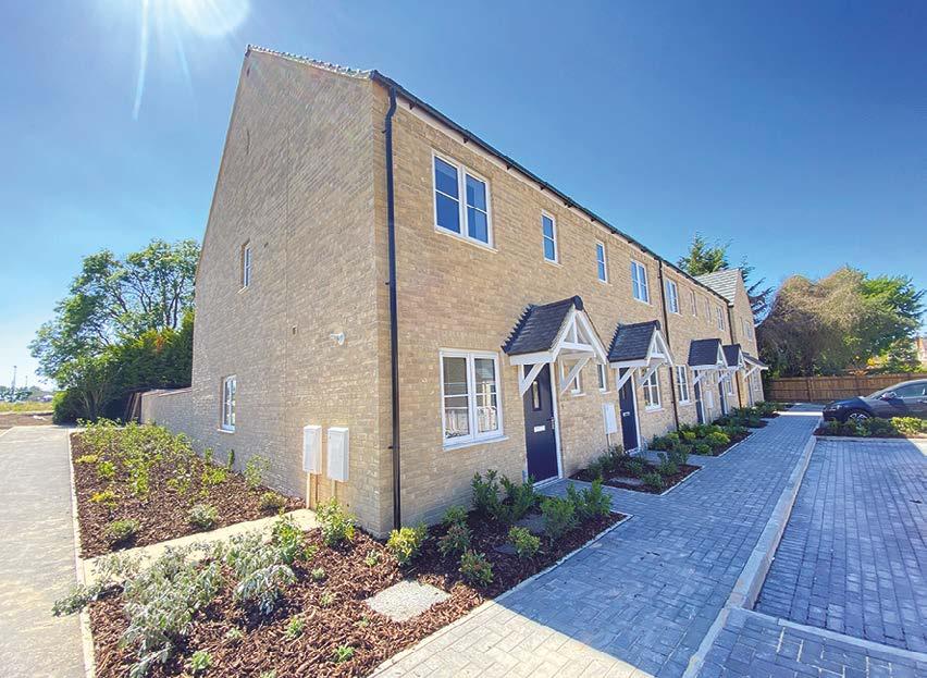
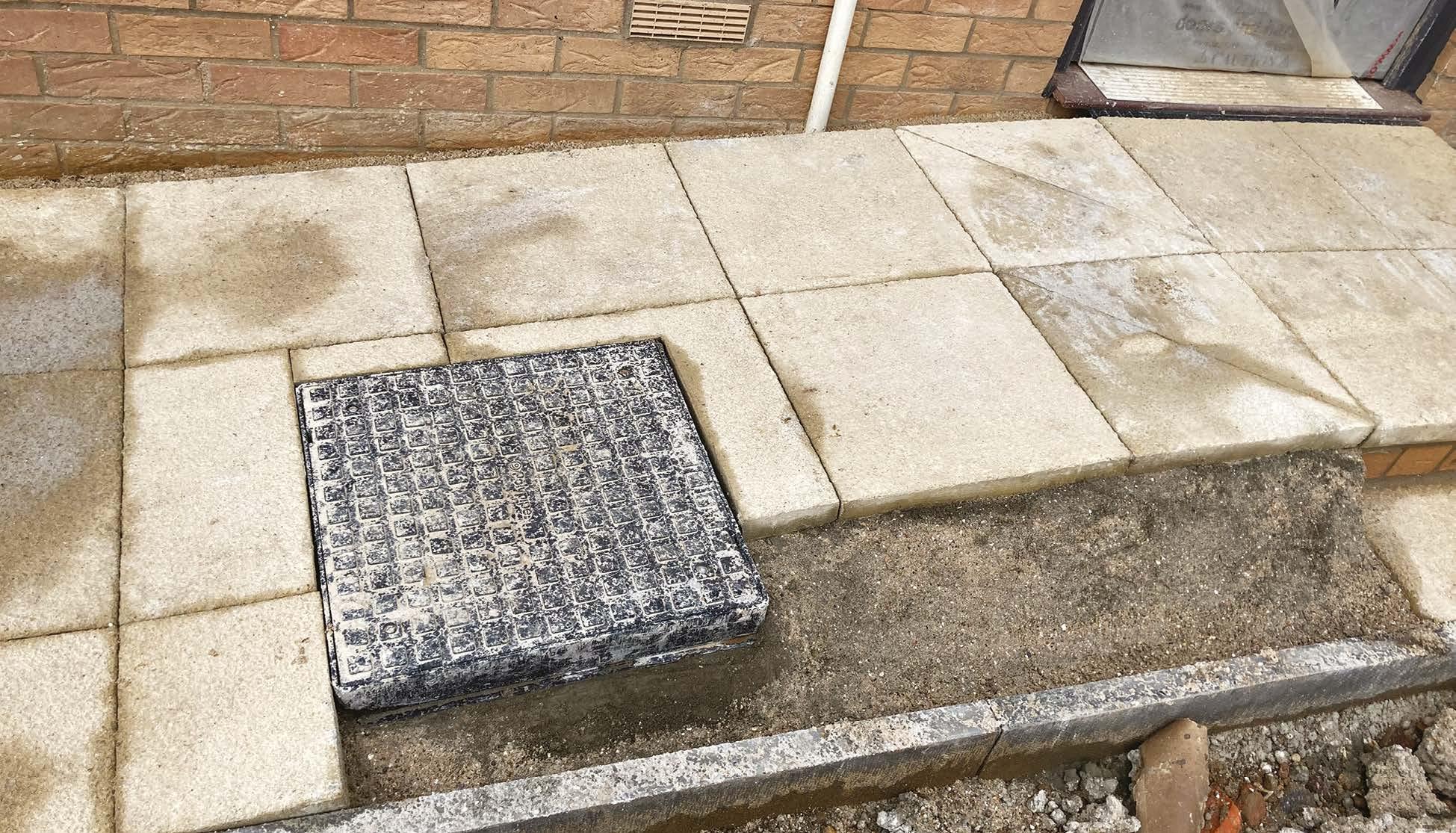
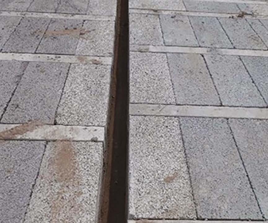
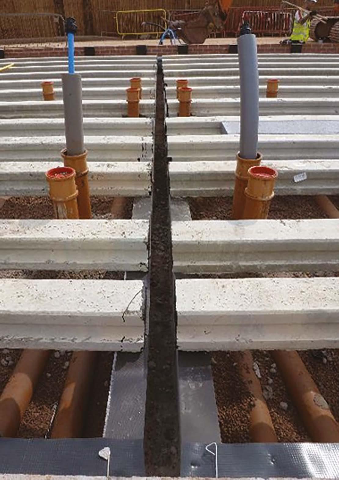
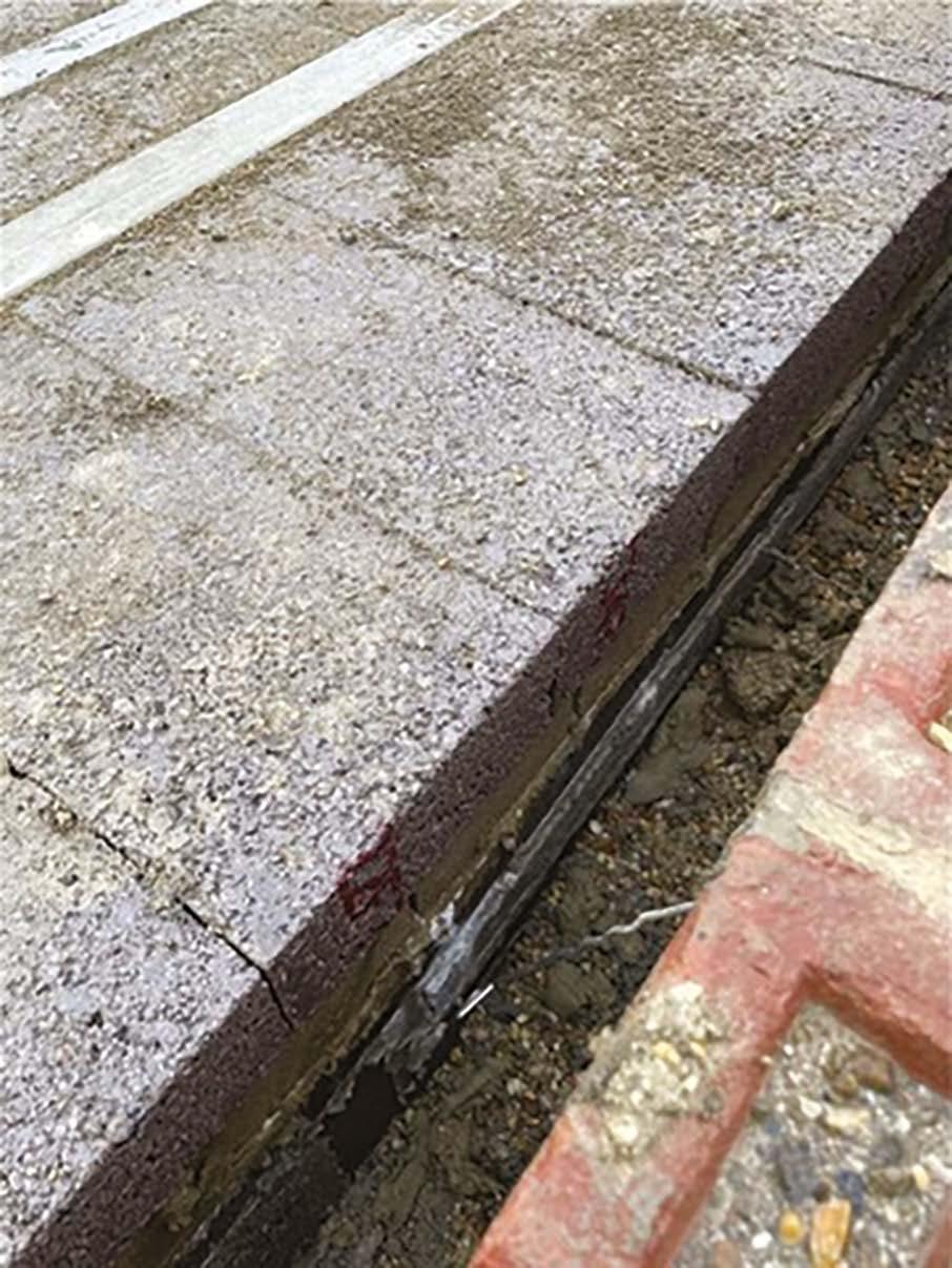
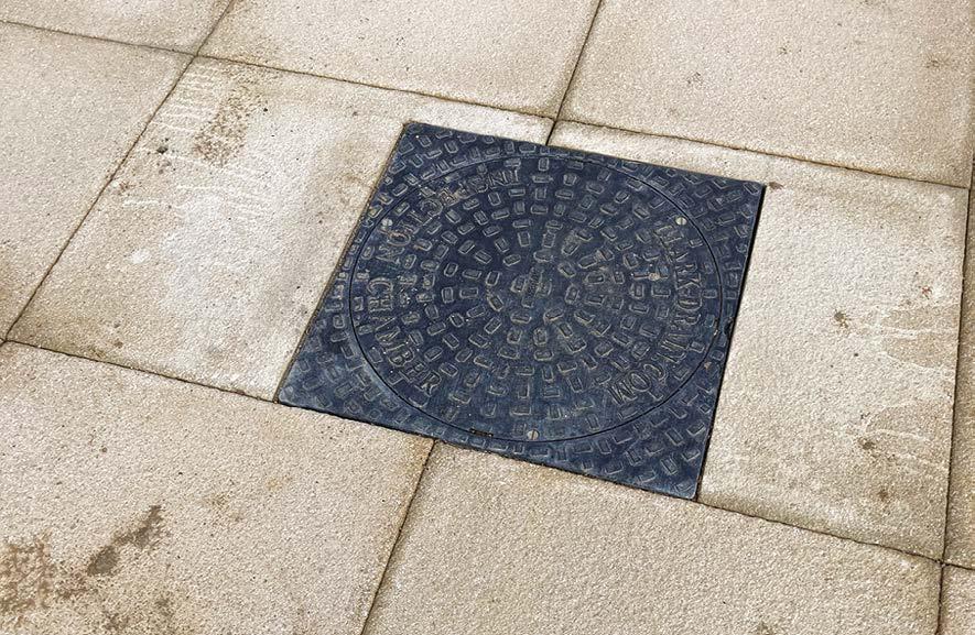
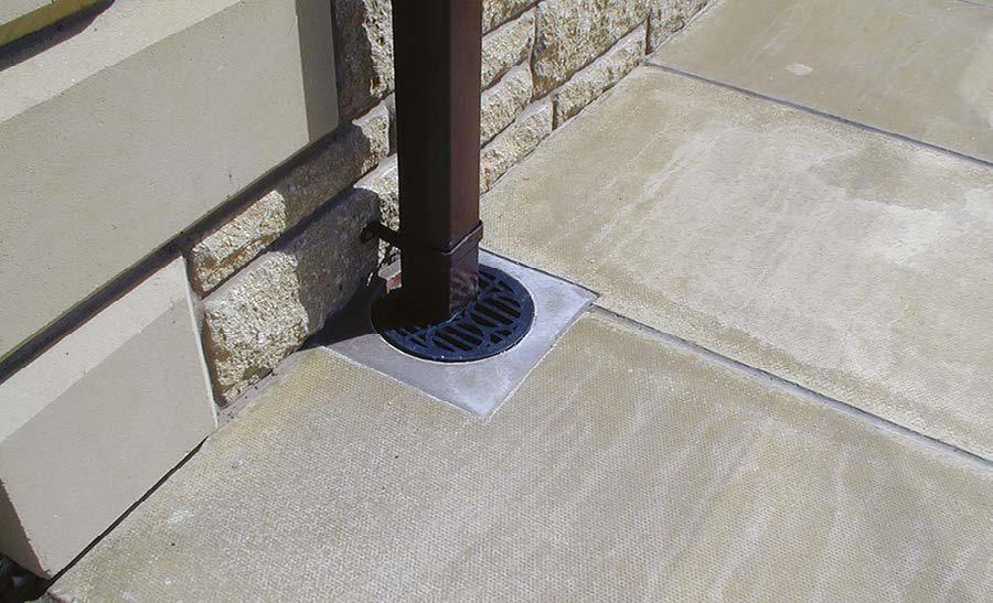
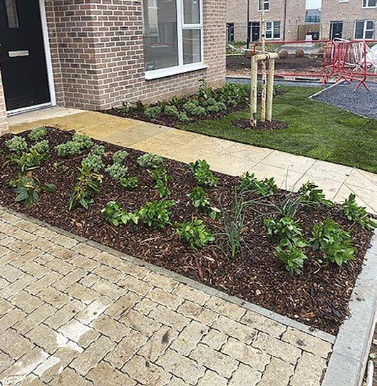
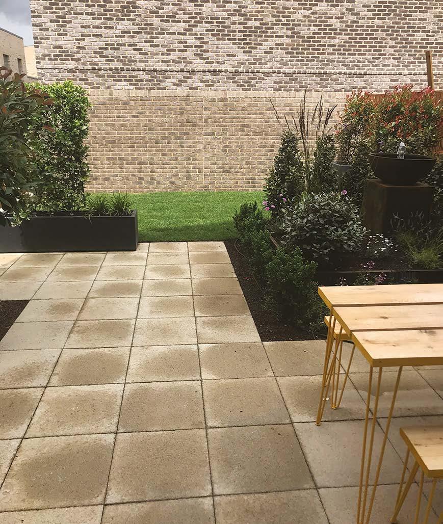
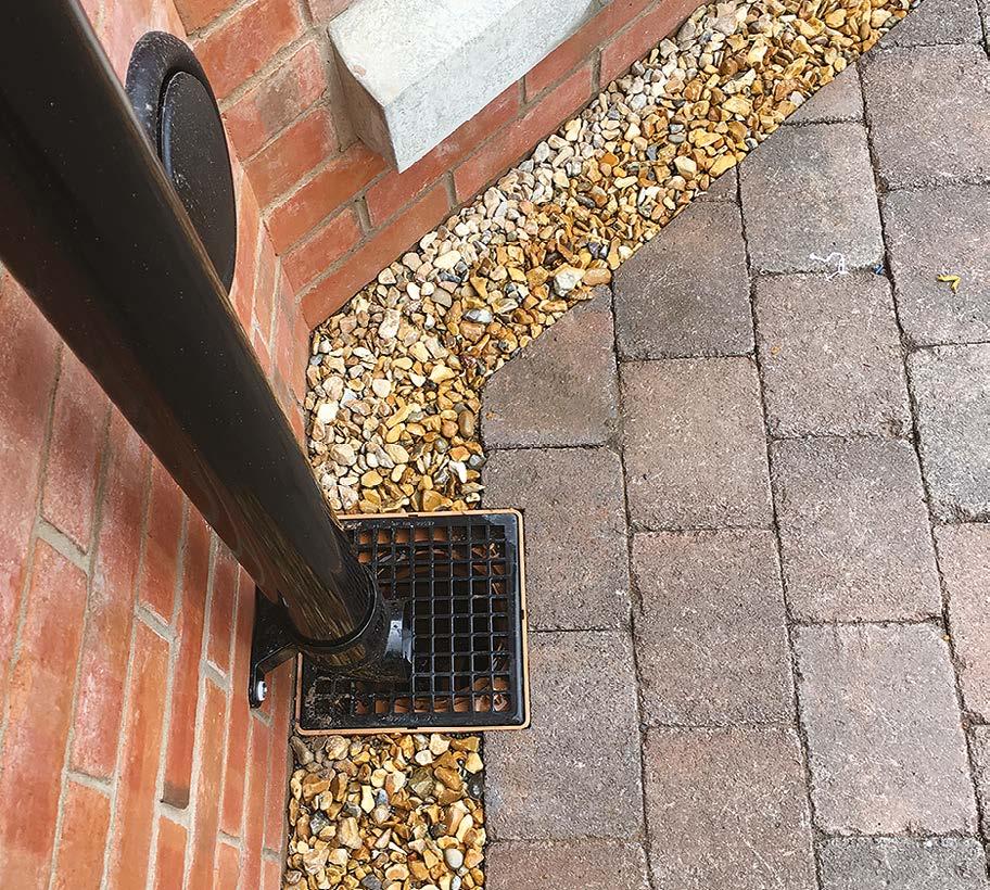
Another very important but often overlooked aspect of good below-ground drainage installation (and incoming water services), relates to the positioning of manhole/inspection chambers. These must be set out correctly from the outset, mindful of the front entrance door location as well as hard and soft landscaping around the home.
Inspection covers have been positioned symmetrically across these terraces located within soft landscaped areas.
An example of where a lack of planning resulted in the inspection cover being positioned half across a ramp. This is unacceptable.
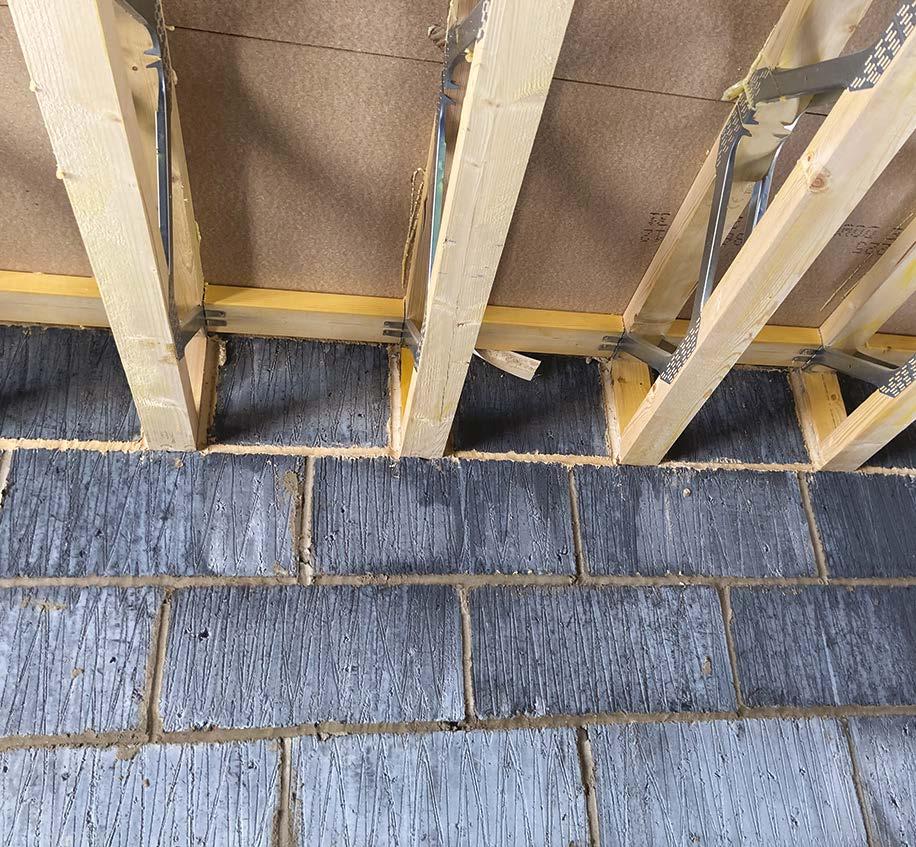
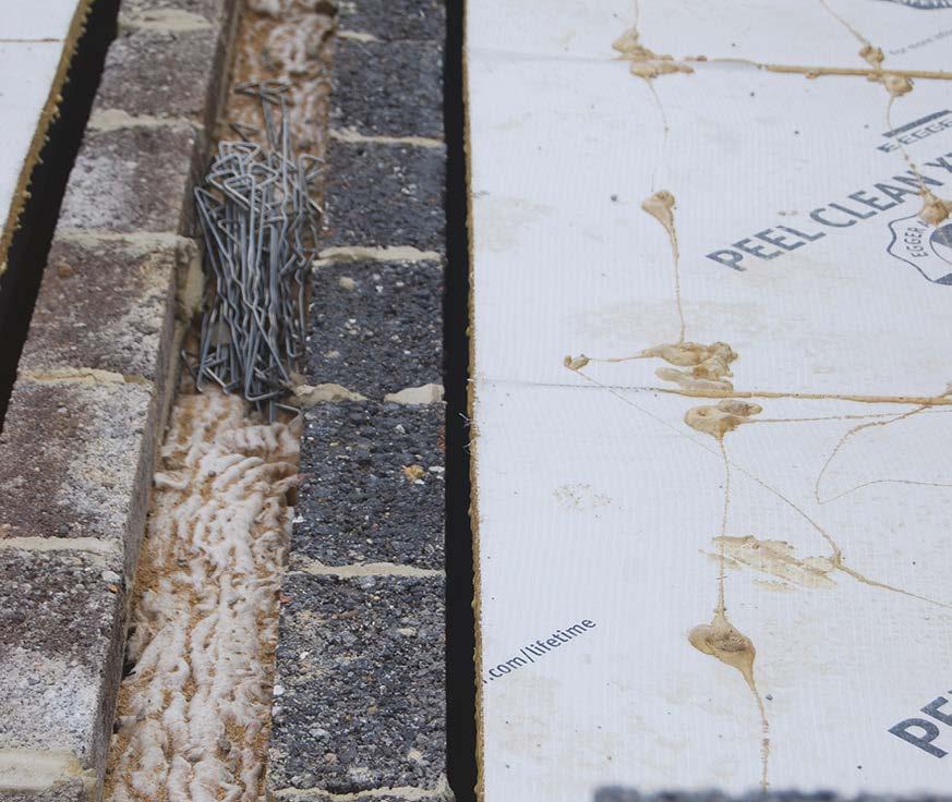
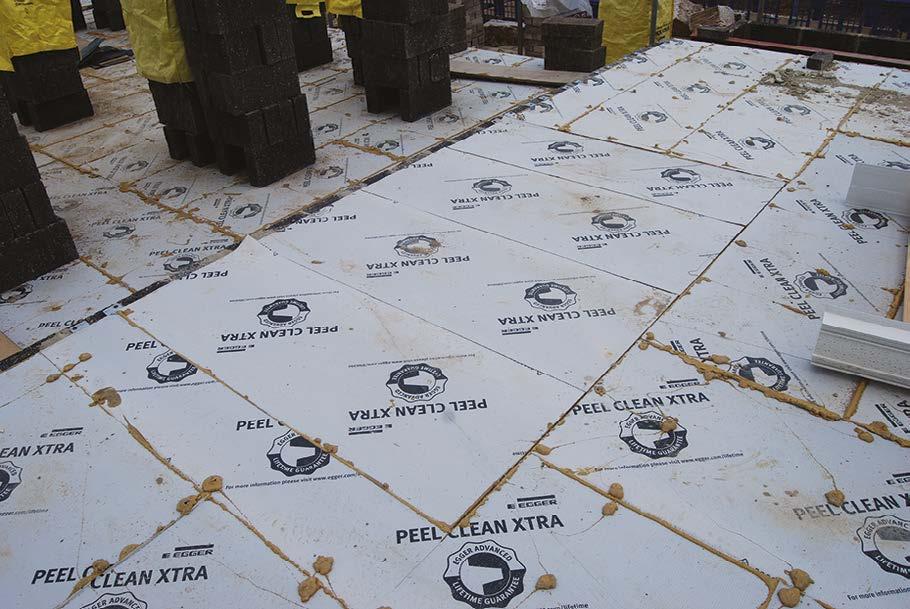
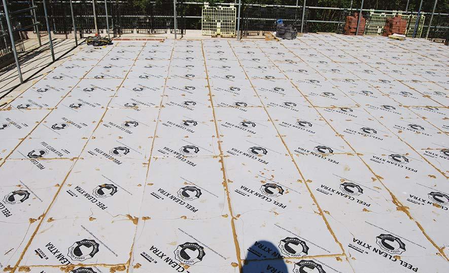
8. Suspended ground floors
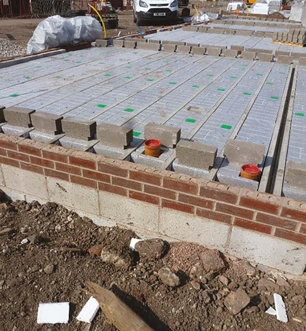
Beams should be laid on DPC and neatly aligned/cut to maintain a consistent cavity width at the party wall, with no steps or ledges.
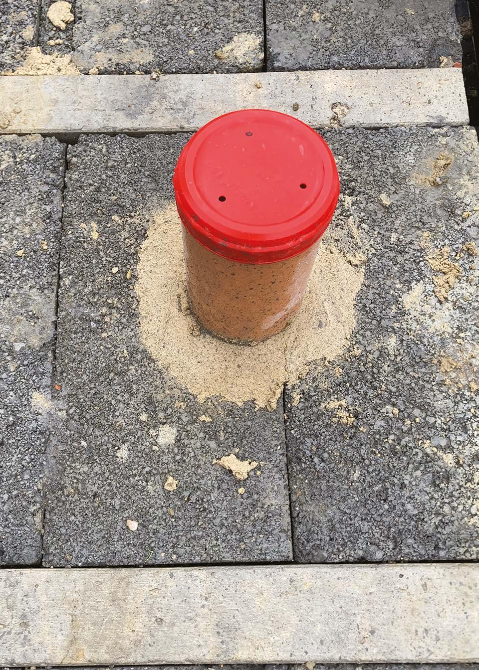
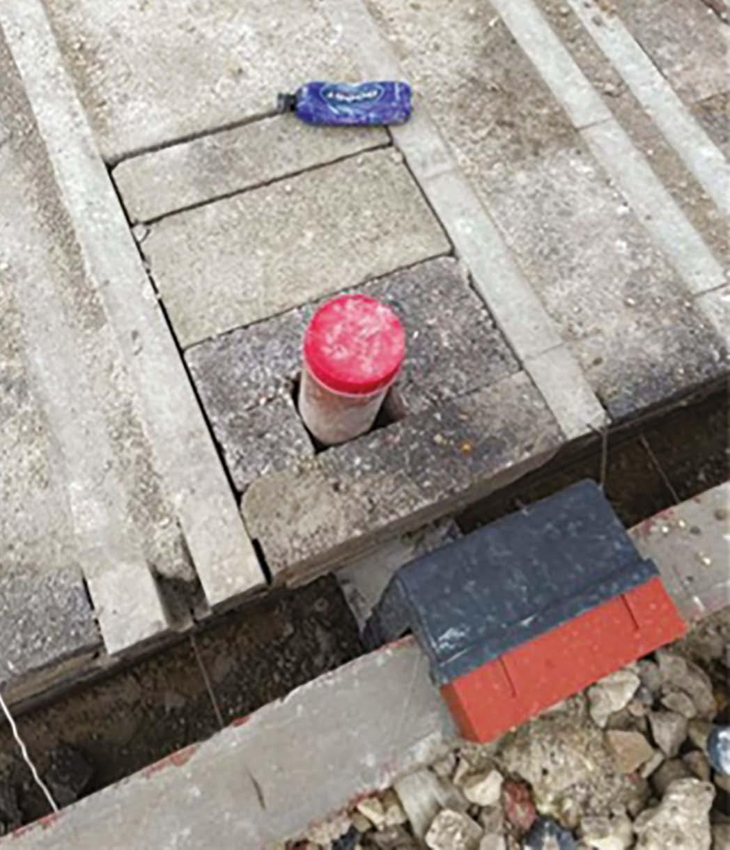
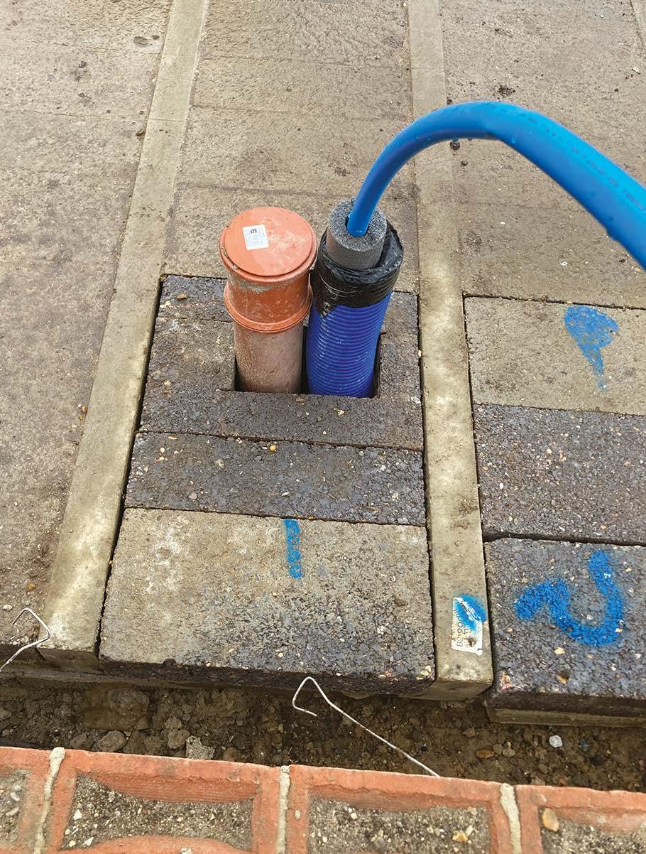
Incoming services insulated a minimum 19mm wall thickness insulation at the time of service pipe installation.
Drainage setting out checked, hydraulically tested and capped.
The subfloor void should be clean of any debris, timber or organic matter.
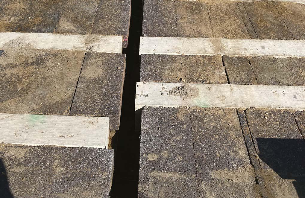
Examples where beams/blocks are of incorrect length or badly installed creating insufficient bearing or projection into cavities, reducing cavity widths, insulation thickness or creating ledges and mortar build-up risks. This is unacceptable work.
An example of neat, acceptable work.
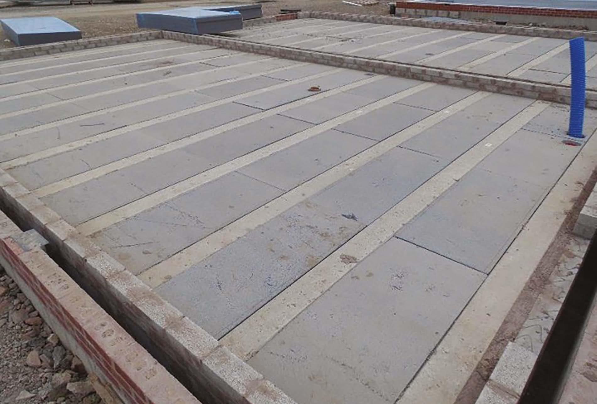
An alternative insulated flooring system. This has been neatly jointed with the service duct carefully drilled.
8. Suspended ground floors
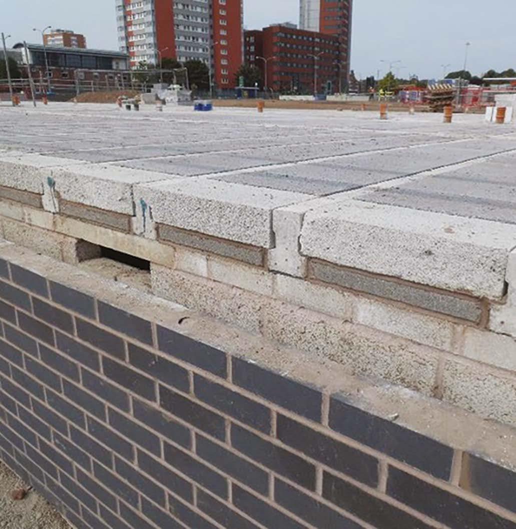
Perimeter blocks have been neatly bedded on dpc.
Blocks have been neatly cut around service and drainage penetrations with blocks grouted as soon as possible.
The incoming water service has been insulated throughout the suspended floor area with a minimum 19mm wall thickness insulation.
Insulation boards have been neatly laid over the beam and block with tightfitting joints and perimeter edges, neatly cut around drainage/service ducts and perimeter insulation to the screed area.
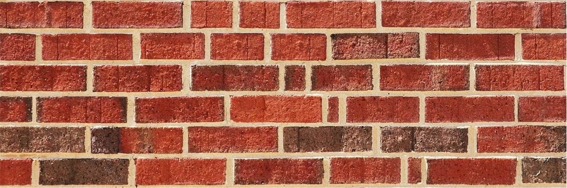
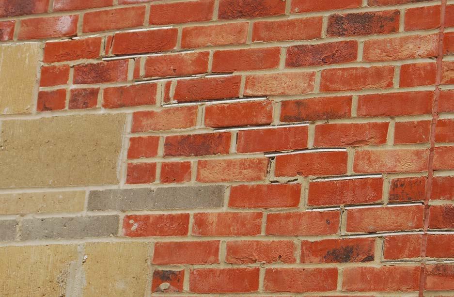
9. Superstructures
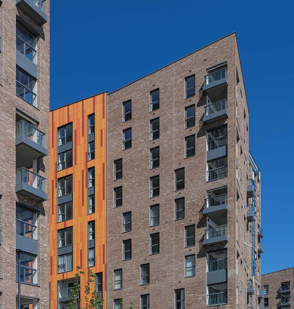
Another key element of any building is its structure and façade. It clearly plays a critical function in providing structural support for walls, floors and the roof, as well as a weathertight thermal envelope for the building.
More than any other element, it provides the building with its outward appearance and character. It is what homeowners, visitors and passers-by see, and pass judgement on our standards.
Superstructure elements (e.g. brickwork or render) need to be constructed right, first time and in a consistent manner, as inconsistencies or later remedial works are difficult, and in some cases practically impossible, to mask.
External Walls
Traditional Cavity Walls
Things to look for:
y Cavities are spotlessly clean
y Lay boards are used to prevent mortar contaminating cavities or laying on insulation.
y Coursing is maintained to ensure wall ties are level and definitely NOT back falling internally.
y Correct wall ties are used to suit cavity width and location with minimum 50mm embedment each end (bedded and NOT pushed into joints).
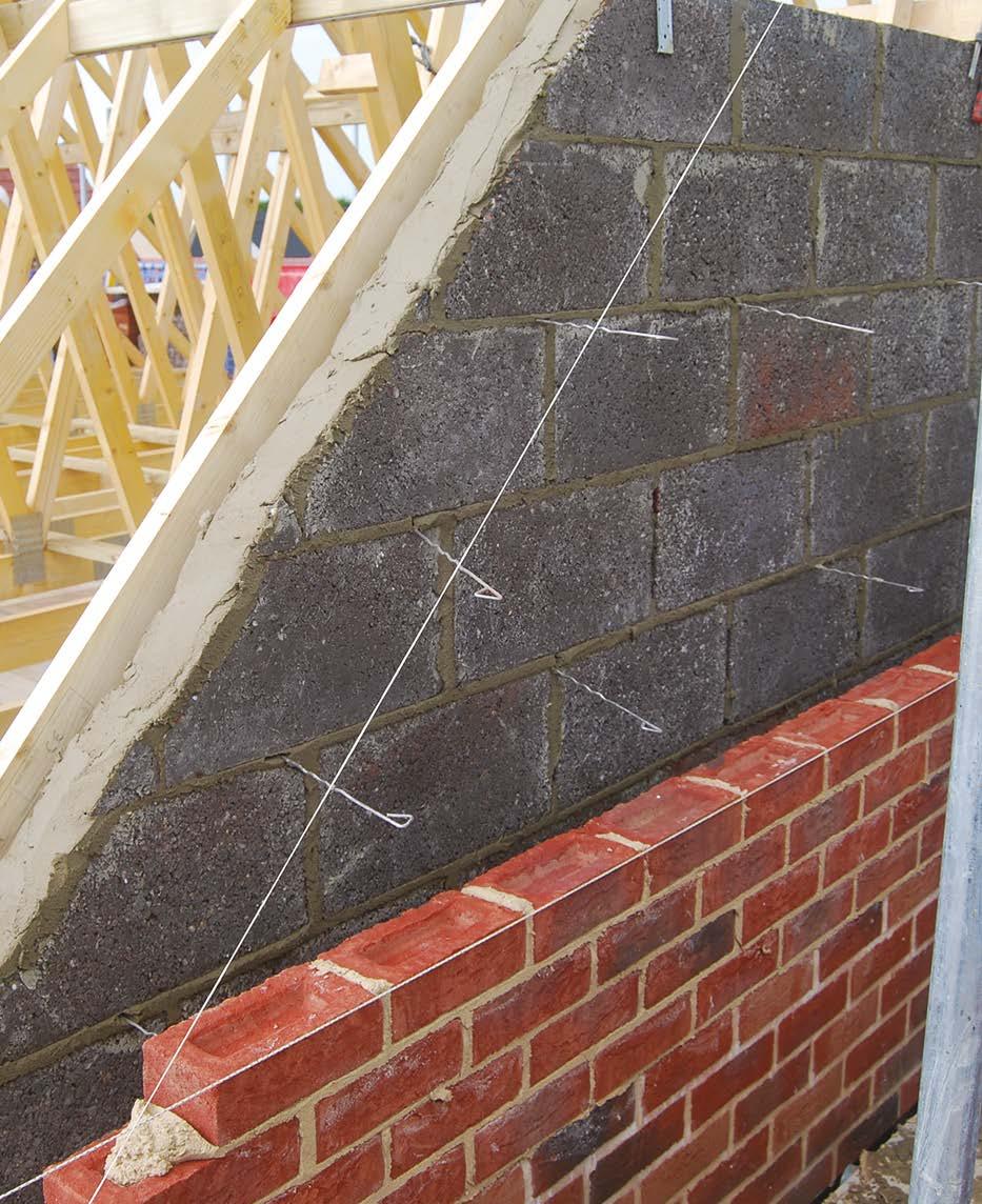
y Wall ties spaces at 900mm centres horizontally and 450mm vertically (both 2 block modules) in a diamond pattern. On party walls – these must not be over provided as this may compromise the acoustic performance of the wall.
y Additional ties to be installed within 225 of openings, gable pitch line and movement joints at every block course / max 300mm vertical centres. Wall ties installed within 450mm at horizontal openings.
Good quality standards are also required to meet necessary energy efficiency standards and prevent dampness or weather penetration. With our climate continuing to suffer increasingly more extreme weather events, our new homes will need to keep warm (or cool in summer) and dry in all conditions.
Superstructures also provide a critical passive fire protection role. They are required to maintain structural fire performance for sufficient time to enable people to safely escape and provide safe access to fire and rescue services, as well as preventing the spread of smoke or fire.
y Bricks and block bed and perpend joints should be fully filled and struck off / ironed in flush with the cavity wall face.
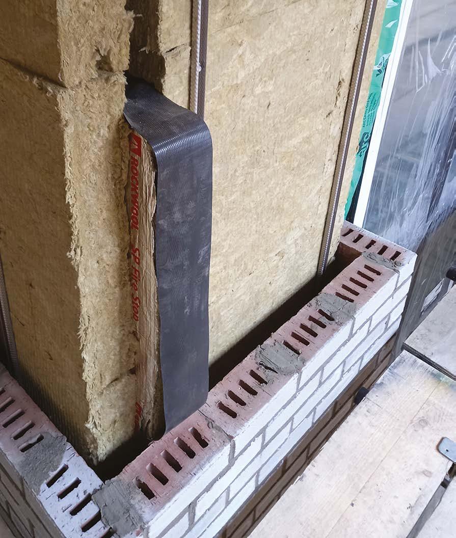
y Cavity trays are required over all lintels, fire barriers, vents or other elements that close or bridge the cavity, as well as roof abutments where external walls transition to internal walls. Trays should be continuous, jointed and sealed with stop ends and clean of mortar. They should upstand a minimum of 150mm (typically 225mm / one block).
y Care should be taken to ensure that cavity insulation is neatly cut in an angle to maintain the thermal envelope at cavity tray locations.
y Weep vents are required to cavity trays (excluding rendered walls) at a minimum of 450mm centres (two bricks). A minimum of two are required per tray and should be installed consistently in relation to projection and horizonal alignment.
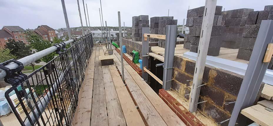
Working area clean and tidy to enable the bricklaying operatives to gain a safe and level access to work.
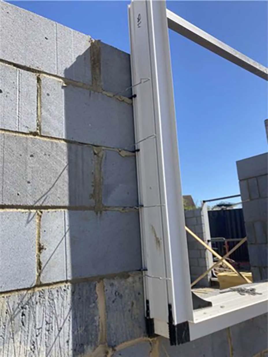
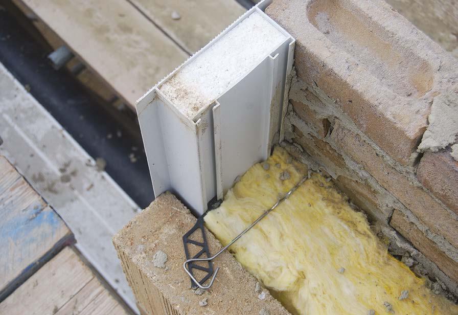
Cavity closer installed using correct proprietary fixings into block bed joints and wall ties installed within 225mm of the opening.
Cavity spotlessly clean, with wall ties clean and all joints filled and neatly finished.
Correct spacing of tiles to perimeter edges (within 250mm of vertical openings / roof pitch to gables at every block course and 450mm centres above and below openings).
Installing longer heavier ties to openings within wider cavities can be more difficult, but is possible.
9. Superstructures
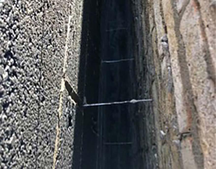
Boards should be used to keep cavities and insulation clean of mortar droppings.
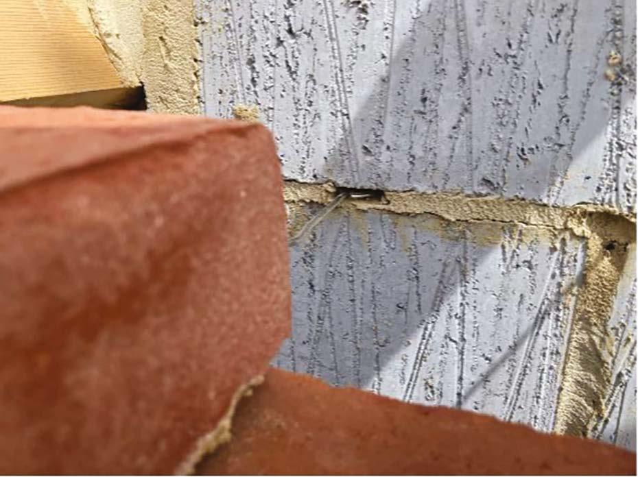
Wall ties must installed within 225mm of a perimeter edge at every block course.
Wall ties must be embedded 50mm in the bed joint as works progress –not pushed in afterwards.
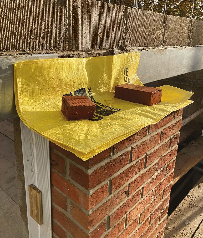
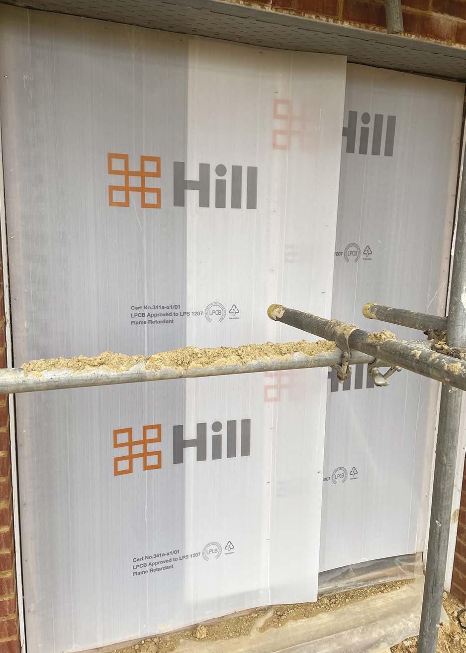
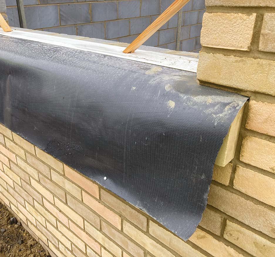
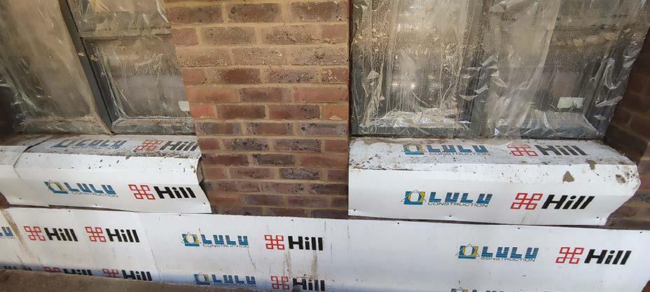
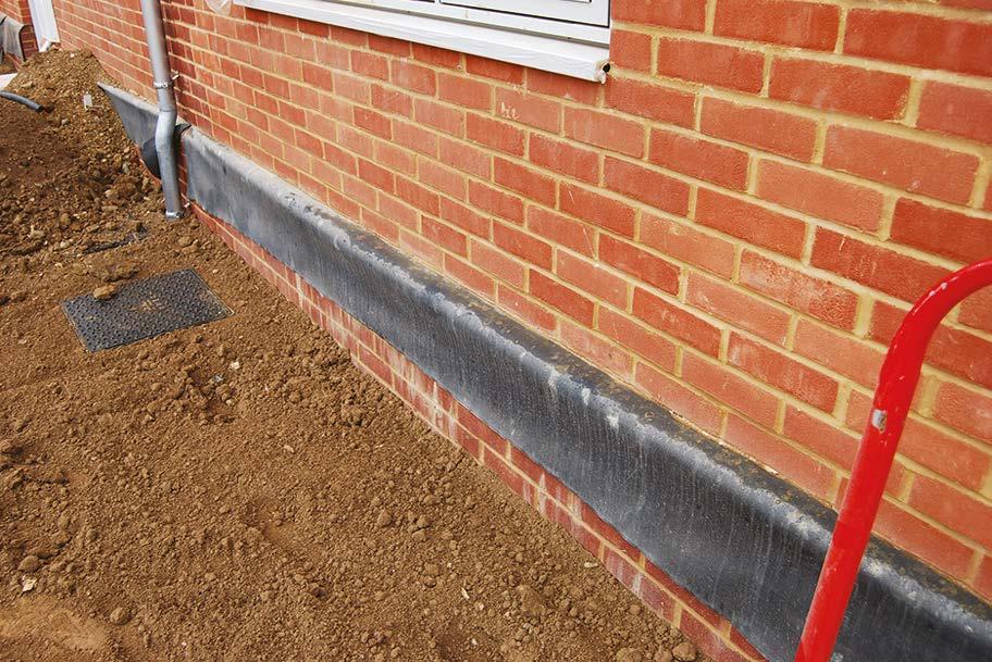
Work should be protected against rain, including cavity insulation. A DPC tray weighted down with bricks will keep cavities dry.
All lintels should bear onto full, uncut masonry units (brick, block or blockette).
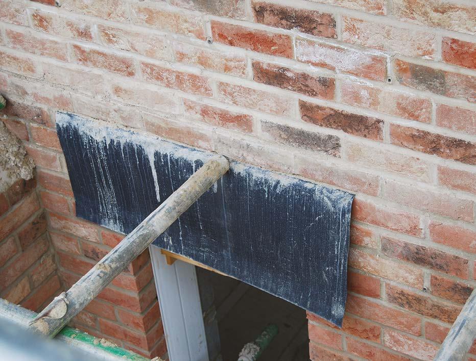
Here we see a temporary tray being laid onto the wall to provide temporary weather protection to the cavity.
Lintels and steel beams must always be bedded on mortar. This ensures that the load is evenly distributed across the bearing face without any point loading, prevents weather ingress through capillary attraction and contributes to air tightness.
An example showing unacceptable practice where a lintel has not been bedded correctly.
An example of good practice where a clean cavity tray is turned up and stop ended into a perpend joint.
9. Superstructures
Care taken to neatly cut the insulation to the profile of the cavity tray.
Weep vents correctly installed directly on the
tray with a consistent projection.
lintel cavity
Non-combustible weep vents to be used on >18m buildings.
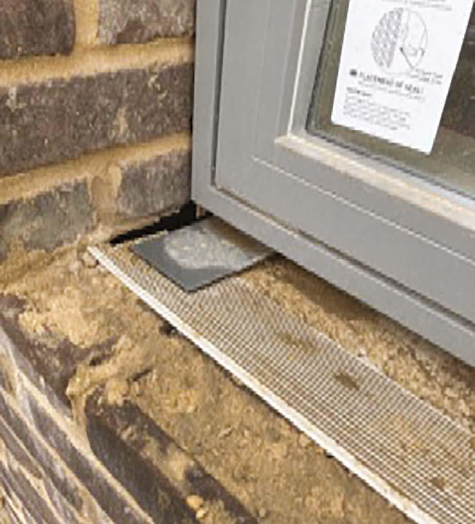
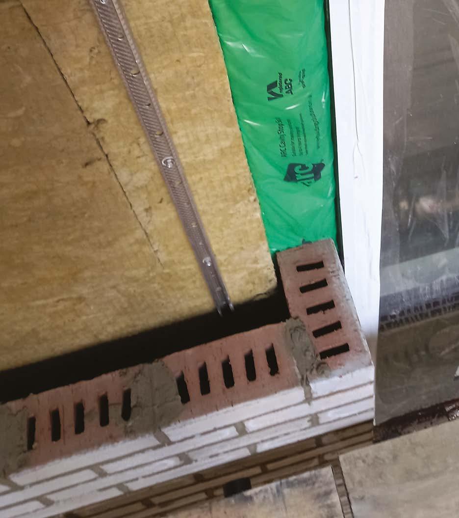
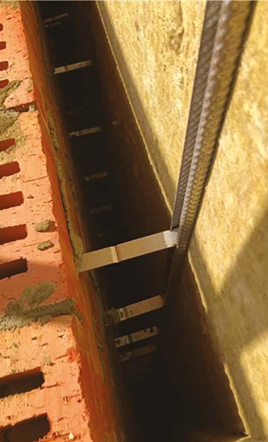
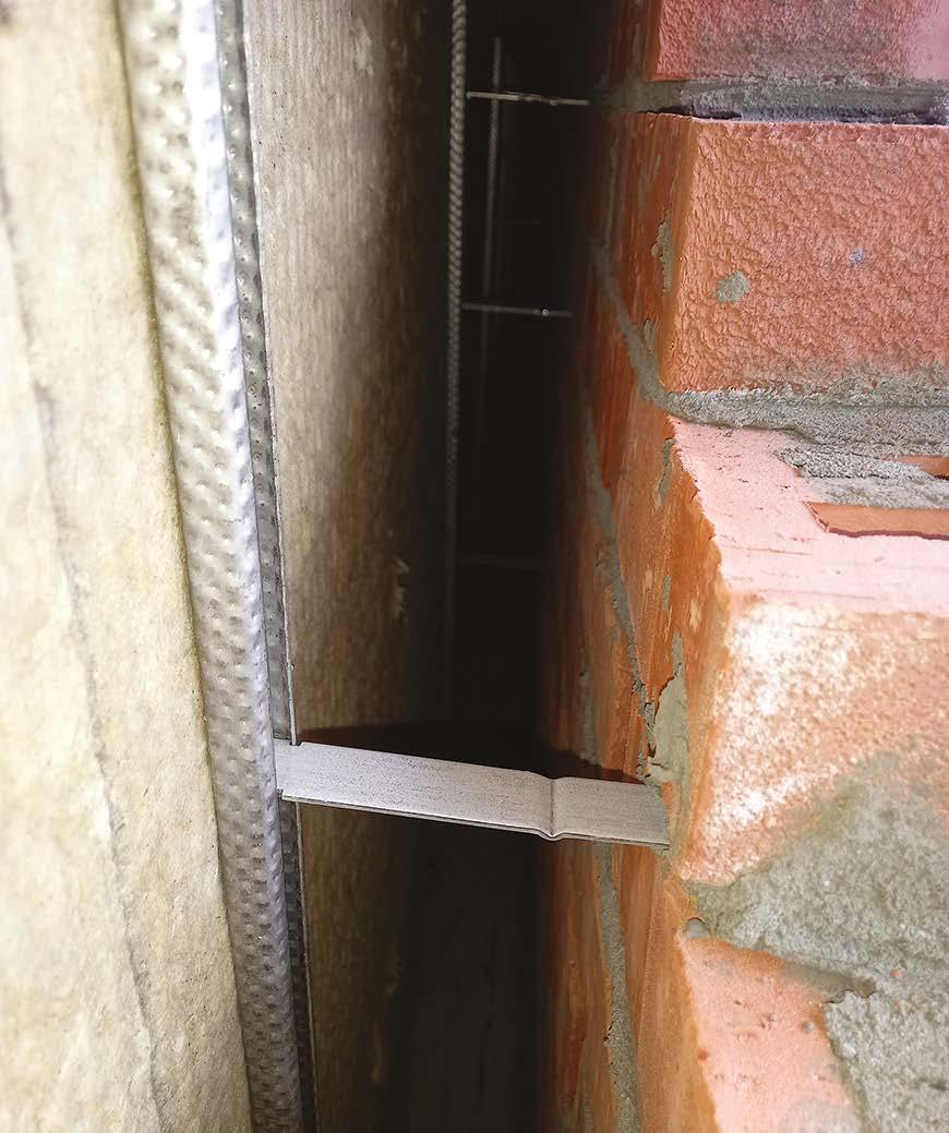
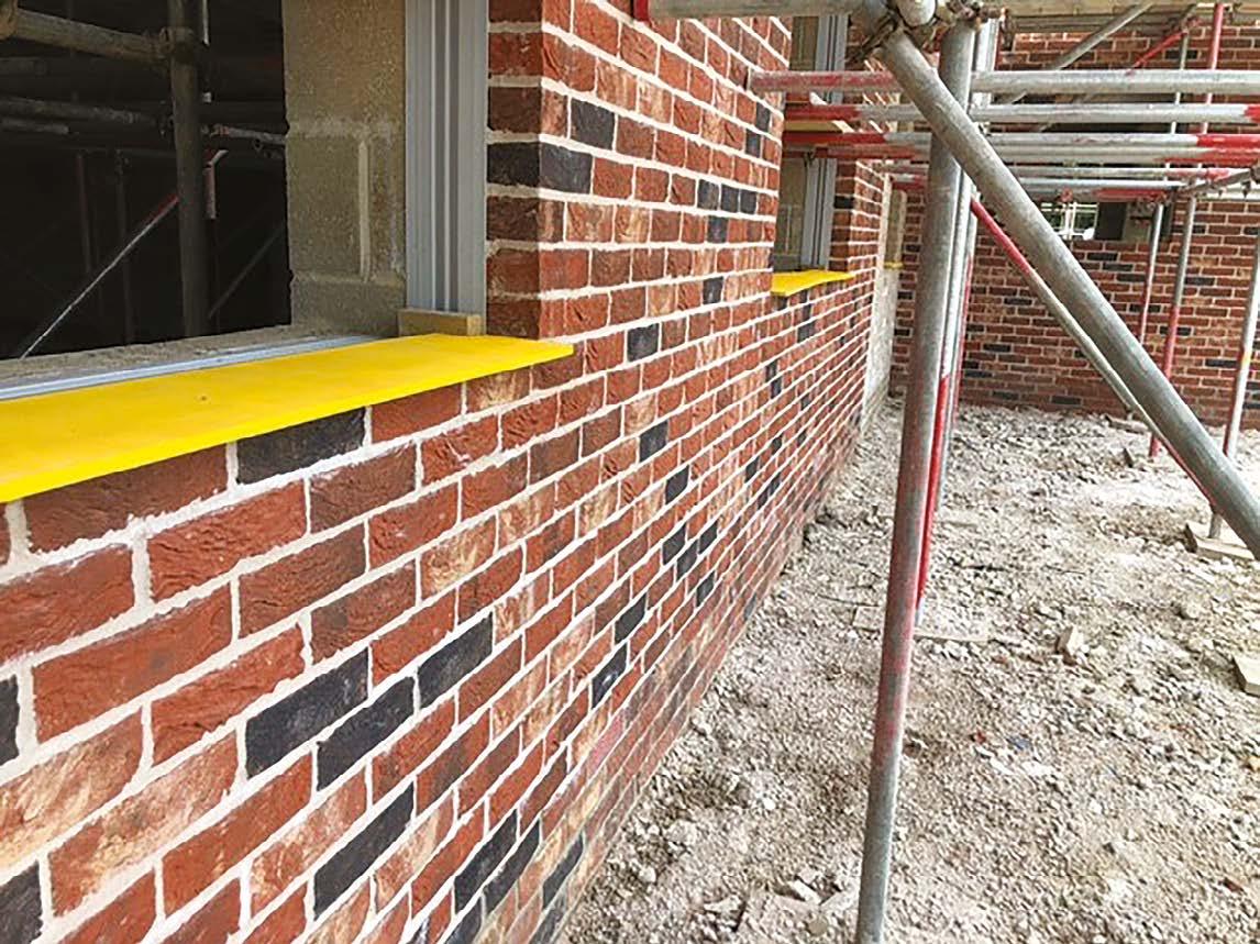
Where deep reveals exist that exposes any part of the cavity in front of the window line, an additional tray is required under the cill of each window to catch and discharge any water that finds its way into the cavity via the cill / brickwork junction.
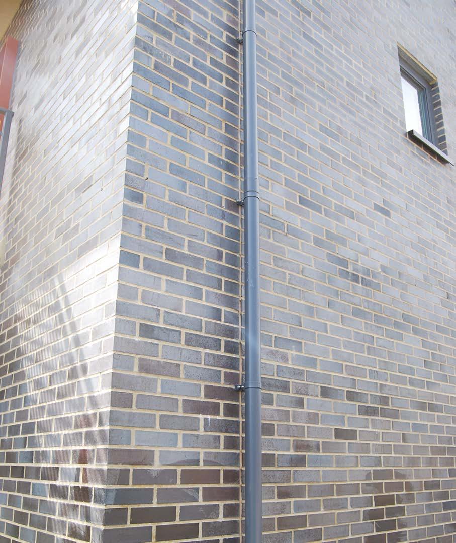
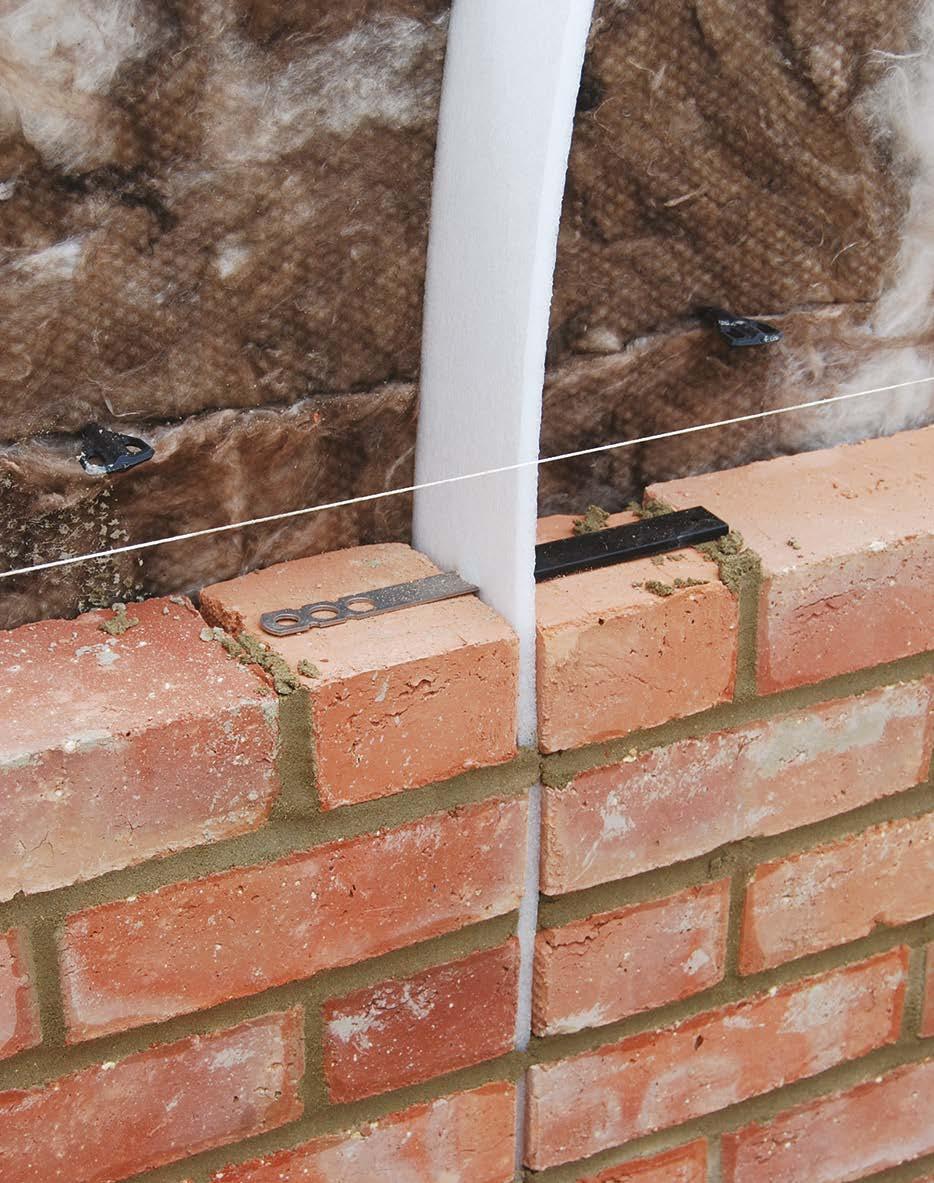
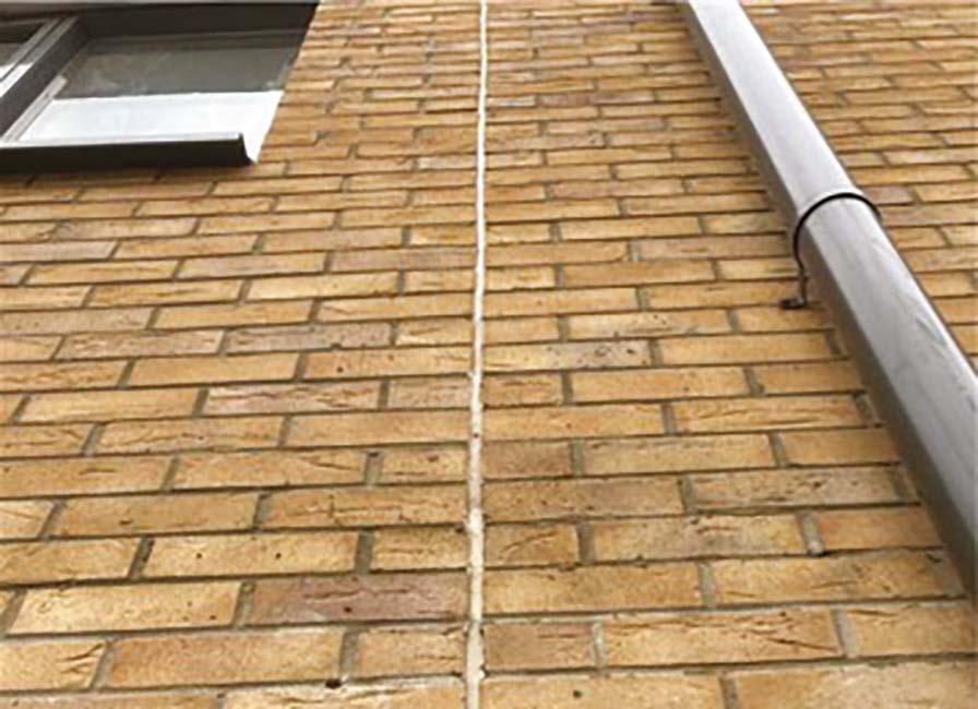
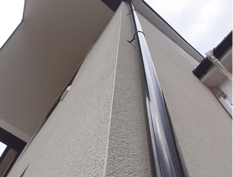
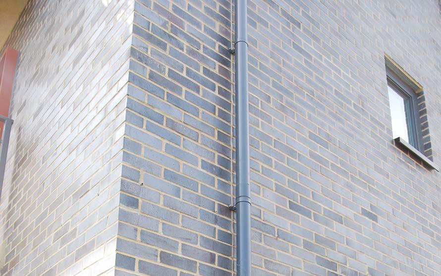
Vertical movement joints should, where possible, be masked by careful setting out of rainwater downpipes. Movement joints should never pass through window or door locations.
Slip ties should be installed to all movement joints.
9. Superstructures
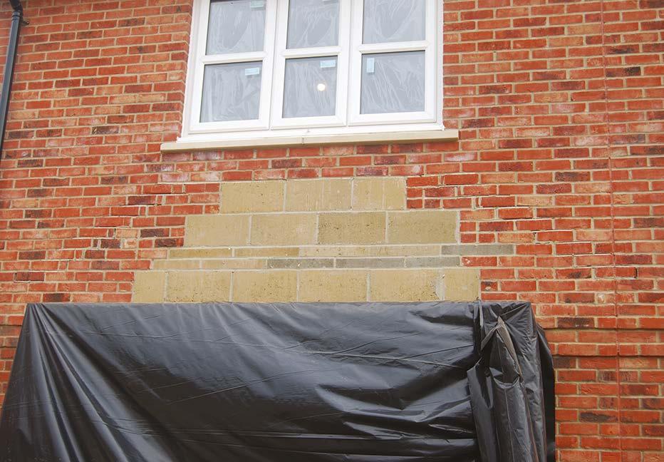
Cavity tray installed towards the top of the bed joint
Cut bricks introduced to ensure heel of trays installed against ‘waterline’
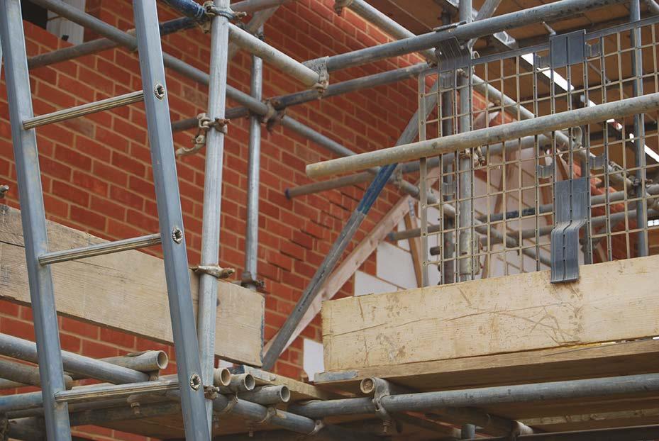
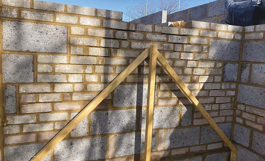
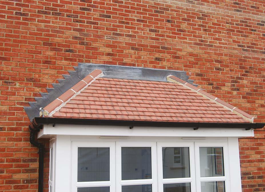
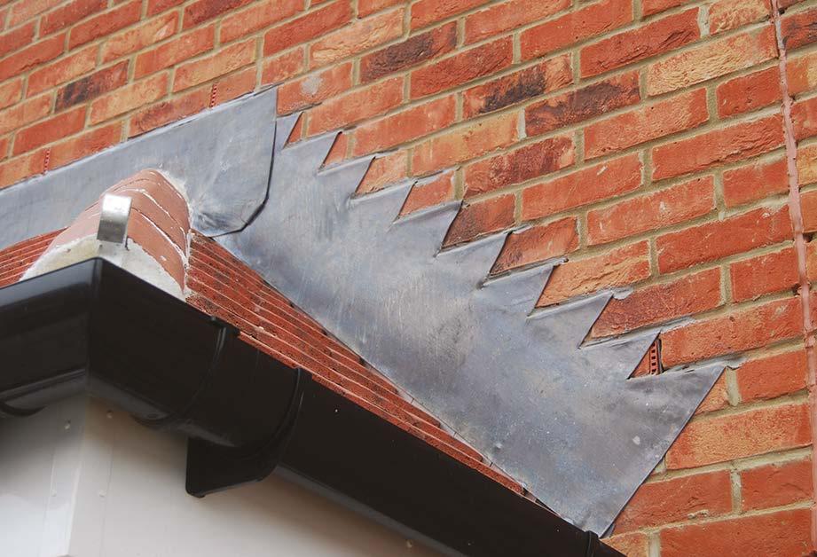
y Proprietary stepped cavity trays must be installed wherever pitched roofs abut external walls (site formed dpc trays are not accepted by NHBC).
y They must be installed with their ‘heel’ in alignment with the waterline as noted below. A profile is required in every case to ensure that the waterline is correctly set out. A double stop-ended catchment tray with weep vent is required at the bottom of the tray cascade.
y Bed joints at the tray locations should be raked out whilst green to allow for the subsequent recessed flashing.
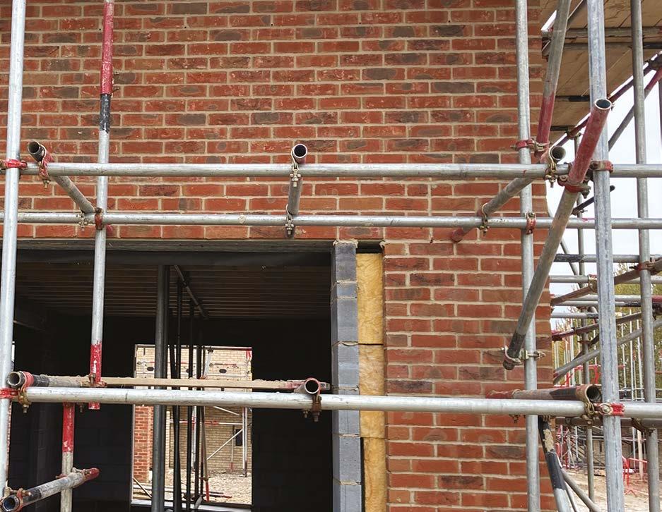
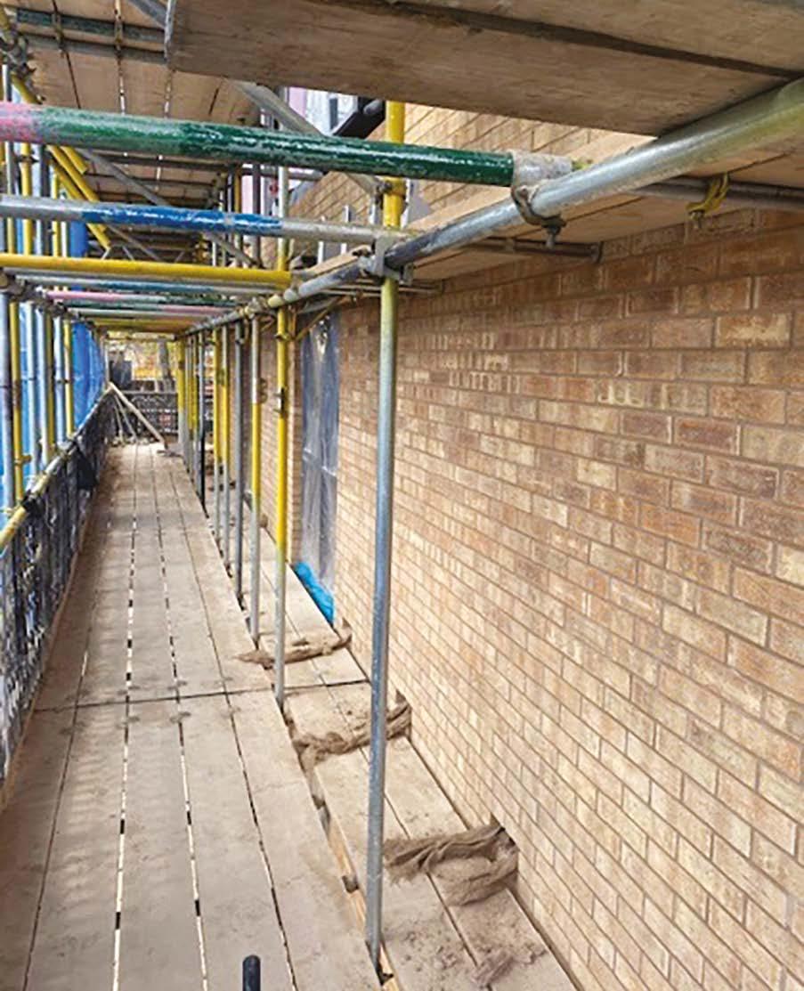
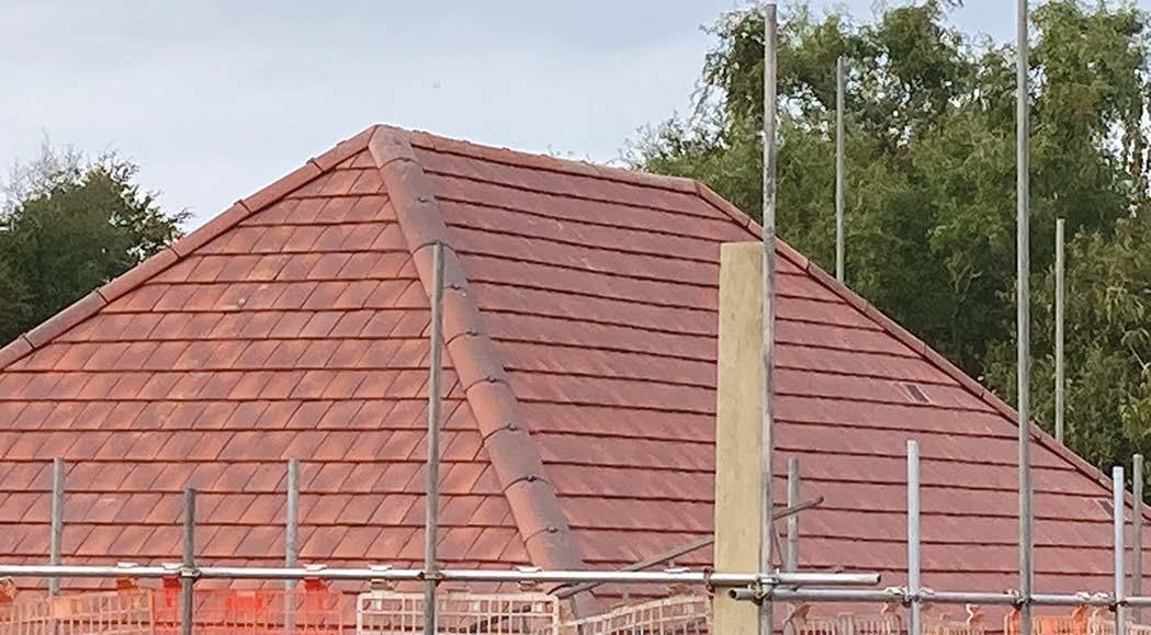
Here the site team has ensured that a truss has been positioned ahead of the scaffold, enabling the precise waterline and subsequent stepped trays to be correctly installed.
Joints raked out below cavity tray by 25mm whilst mortar green
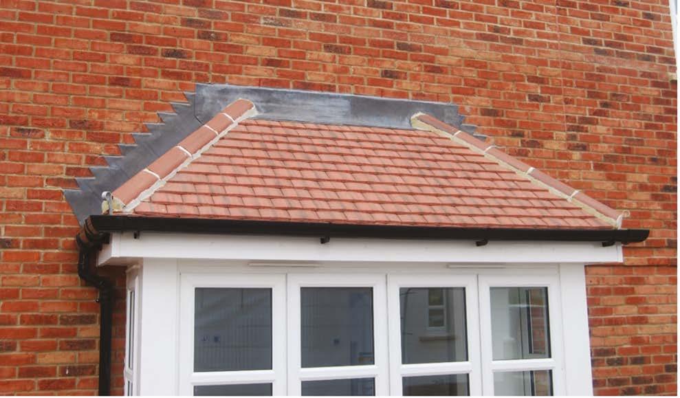
Joints raked out at stepped cavity tray locations ahead of this hipped bay roof.
Here is an example where the setting out of the tray is incorrect. The heel of the catchment tray does not coincide with the waterline.
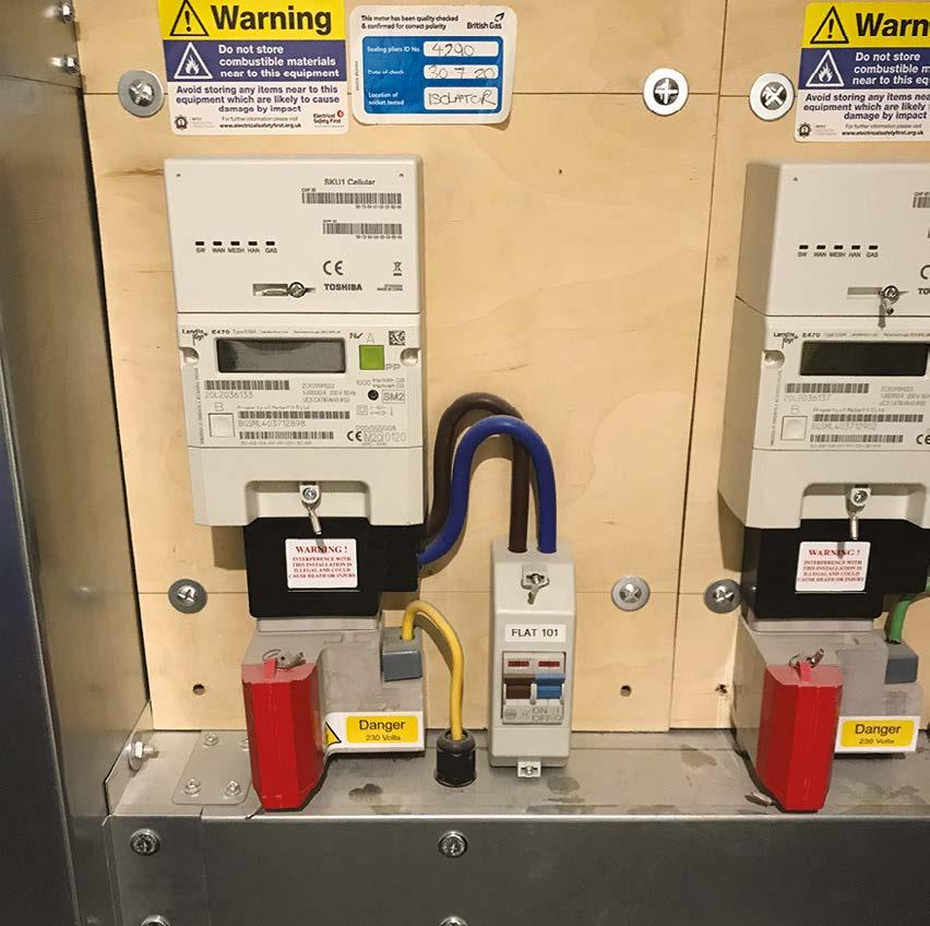
Correctly located tray and weep vents to this recessed electrical meter box (one course above the opening to accommodate the meter box flange).
Tray and weep vents correctly installed to this mono pitch low level roof abutment at a minimum of 75mm above the pitched roof / wall intersection.
Tray and weep vents correctly installed to this parapet / external wall abutment.
Vertical trays correctly installed to the sides of this flat roofed bay.
A finished hipped roof bay with weep holes evident in the bottom catchment tray.
9. Superstructures
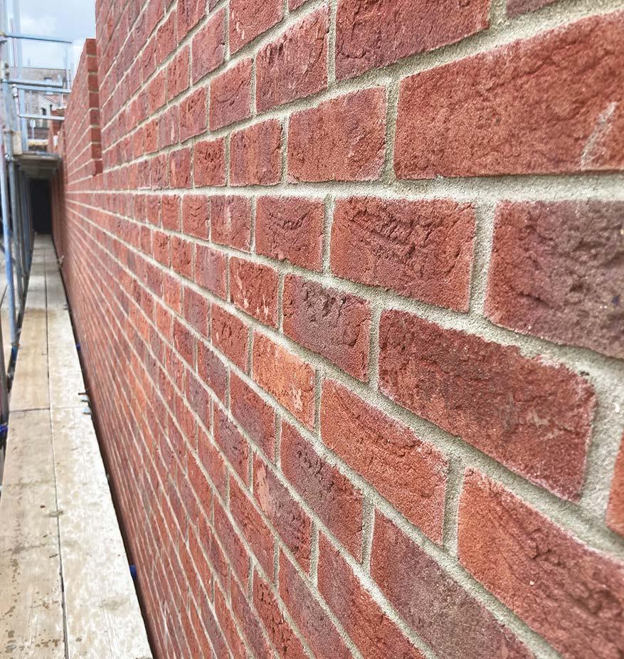
Straight bed joints.
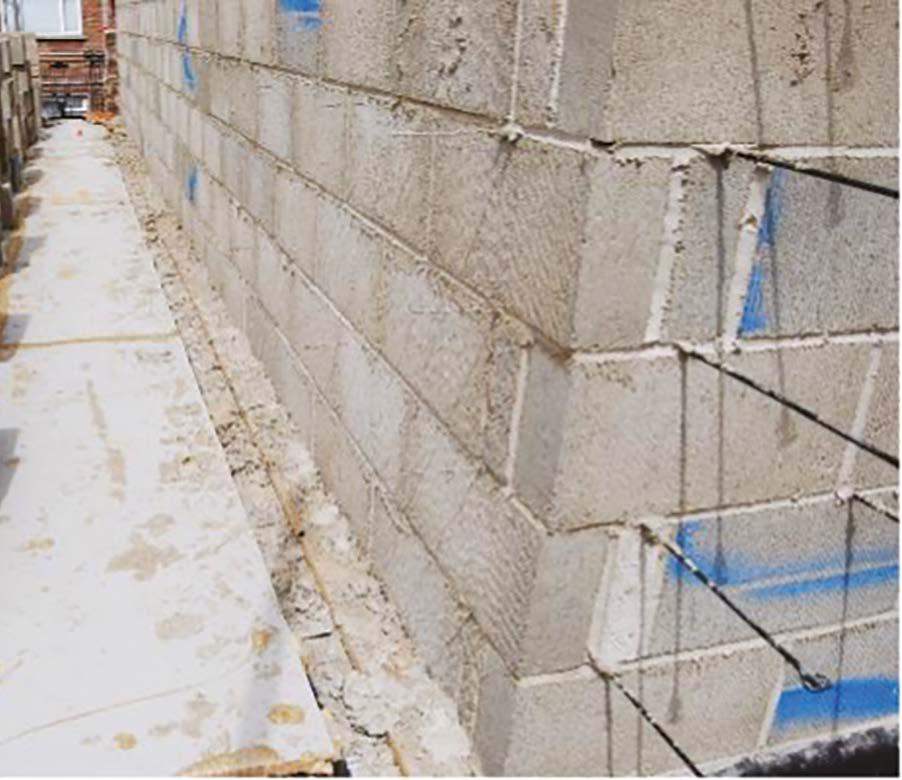
Impressive that this wall has been laid and finished with pride even when it is to be plastered.
Neat work even under a challenging lighting condition, confirming a significant flatness and consistency of finish to these walls.
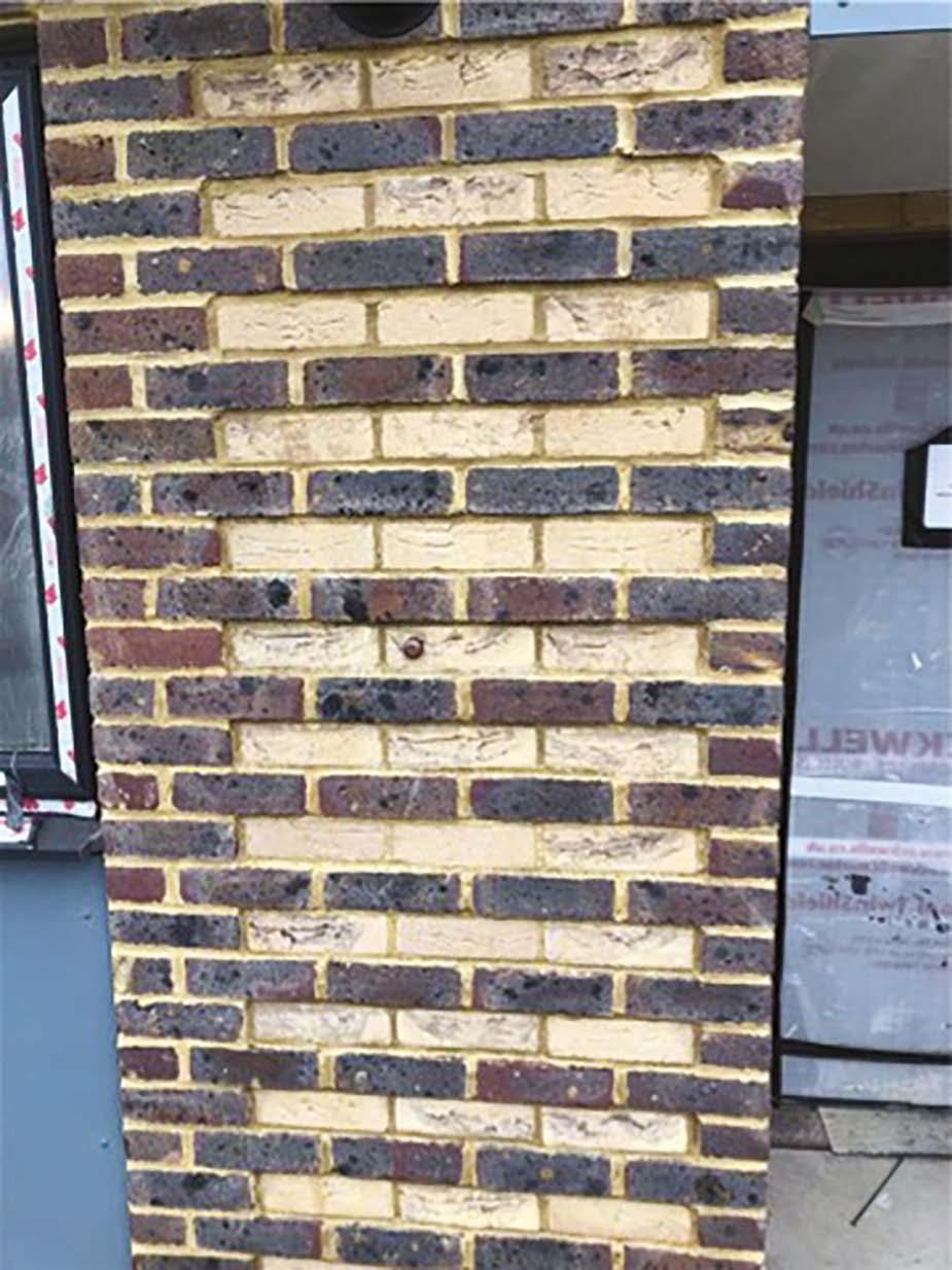
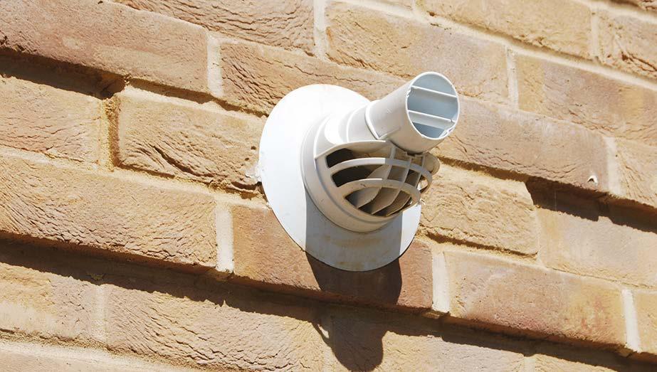
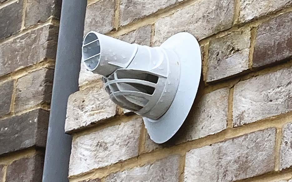
Care taken to consider how to accommodate a flue through this brick detail (the same would apply for a ventilation grille).
A similar detail where no thought was given.
On the face of it, this party wall looks neatly constructed. On closer inspection the wall ties have been installed at 450mm centres horizontally (not 900mm). This creates a more rigid wall that provides an increased sound path across the wall and is therefore not acceptable.
Neat work to complex details.
Plumb perpend joints indicating a consistent bond.
9. Superstructures
Joist ends neatly filled with blockwork (Note – that NHBC Standards 2024 now require these joist ends to be mastic sealed so that air tightness is maintained during timber shrinkage or movement.)
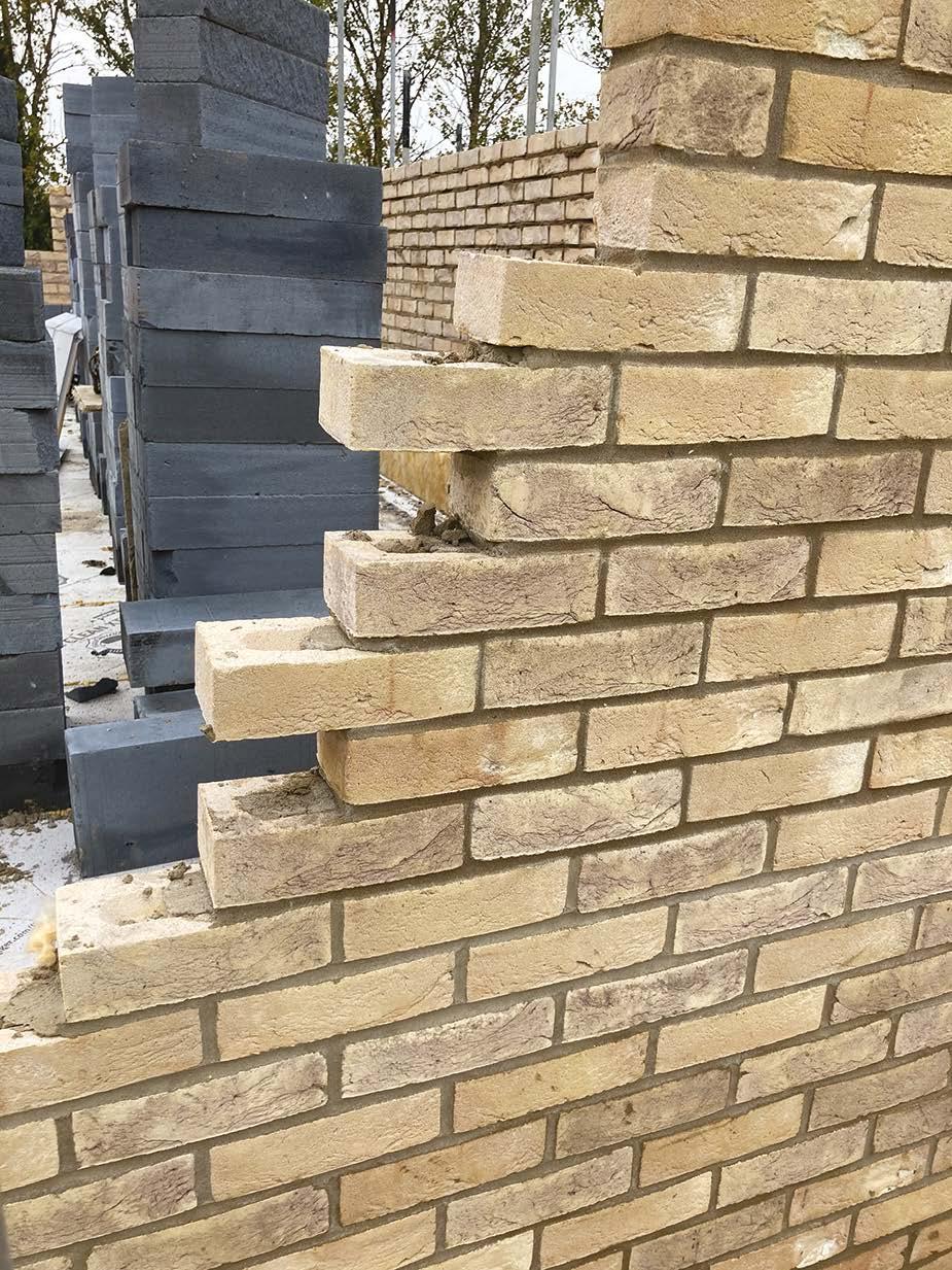
‘Toothing’ of brickwork is not permitted as it often leads to unfilled bed joints. Where work cannot progress to an opening, it must be raked back and not toothed.
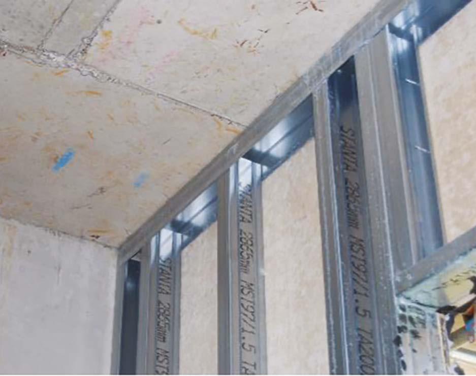
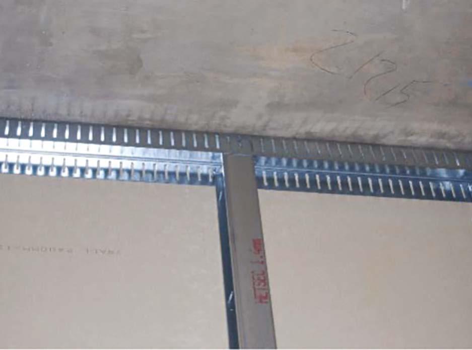
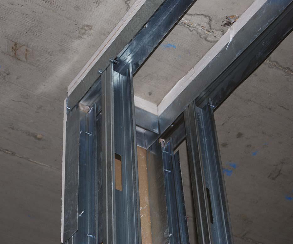
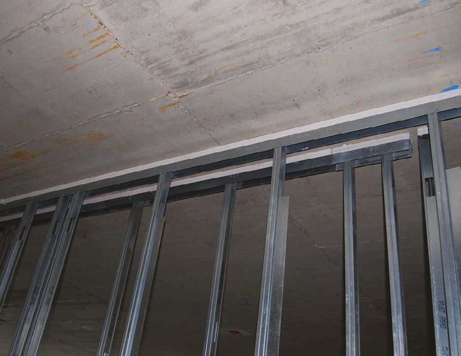
Framed Buildings
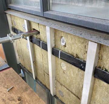
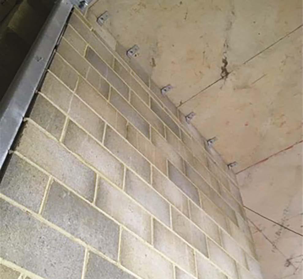
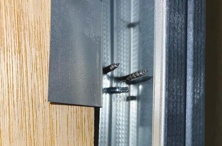
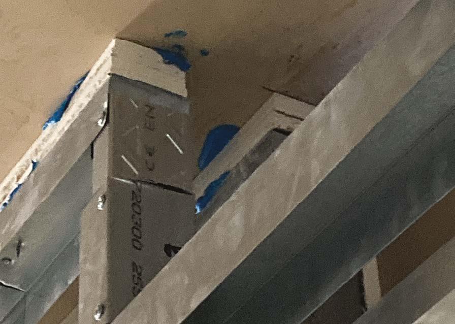
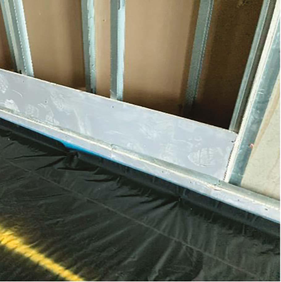
Light gauge steel infill panels are installed with deflection heads to permit structural deflection.
board to the light gauge steel frame is sealed to all perimeters using Class B EPDM.
Sheathing
Preformed corners used on all cavity trays (non-combustible type required to buildings >18m). Site formed corners are not to be used, preformed flexible corners are now available and acceptable.
Windows and duct penetrations are sealed against the sheathing board using Class B EPDM.
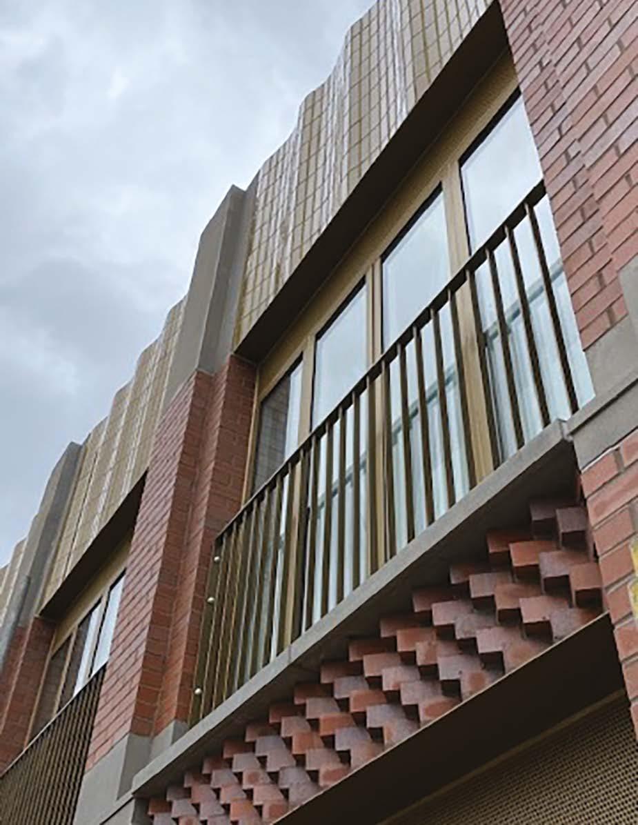
Cavity barriers are required to all party floor and wall locations. Here, exceptional care has been taken to neatly cut the fire barrier tightly around this dog toothed brickwork design.
Care has been taken to carefully cut the fire barrier around this masonry support angle.
9. Superstructures
Vertical cavity closers and barriers are tight fitting.
Full bricks or rotated cut bricks are used to ensure a full-face contact with the cavity barrier.
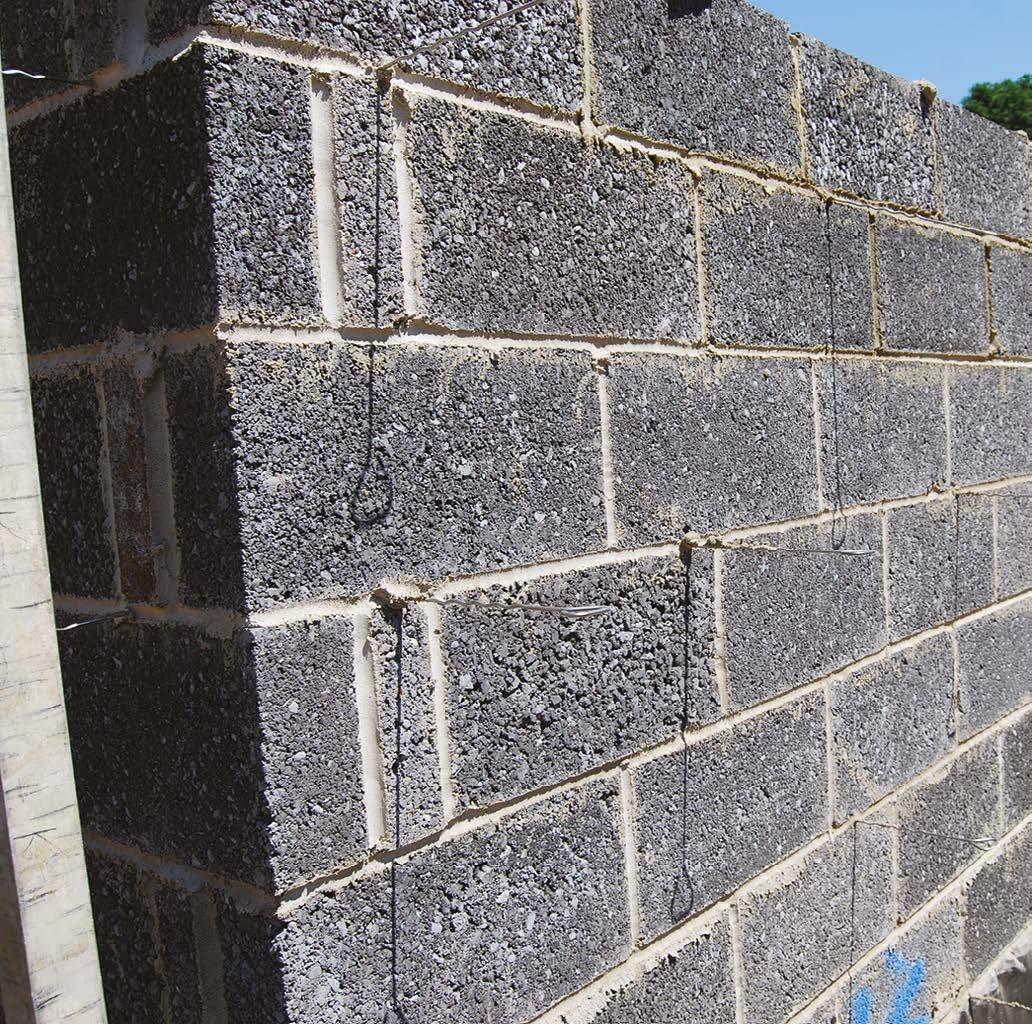
Spotlessly clean cavities and wall ties with all bed and perpend joints fully filled.
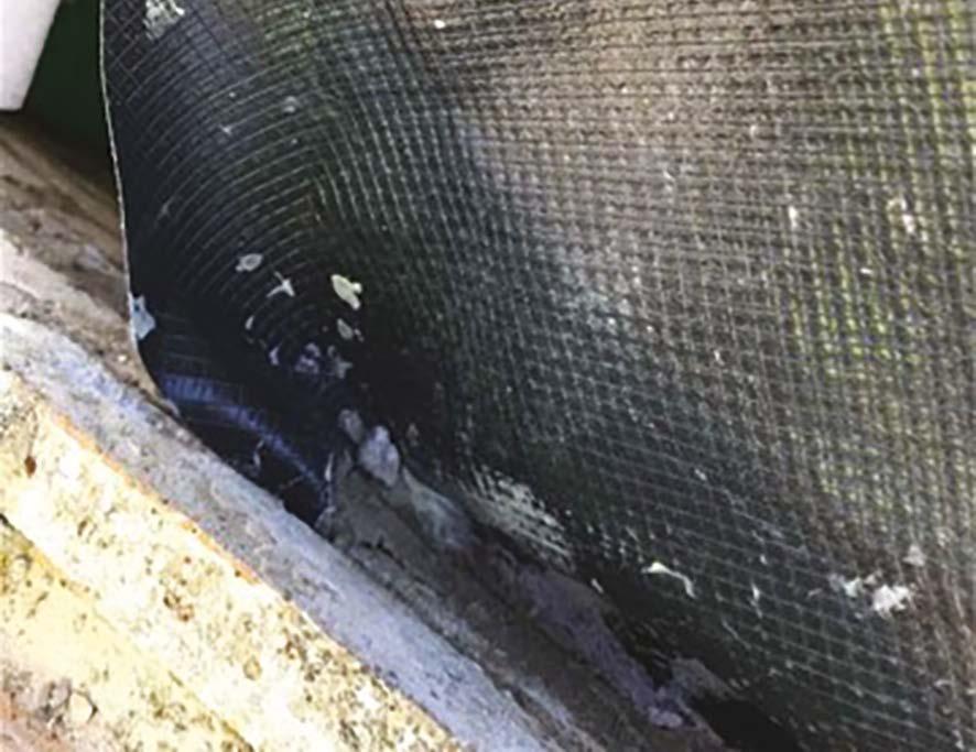
A clean and tidy working platform with pockets formed and temporary hessian laid on the cavity trays (removed via the pocket) to present a clean mortar-free cavity tray on completion.
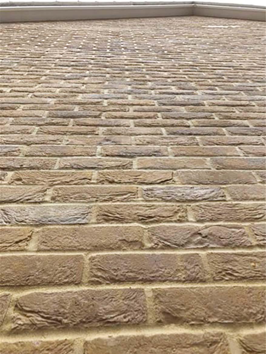
An example of some complex and neatlyfinished face brickwork.
9. Superstructures
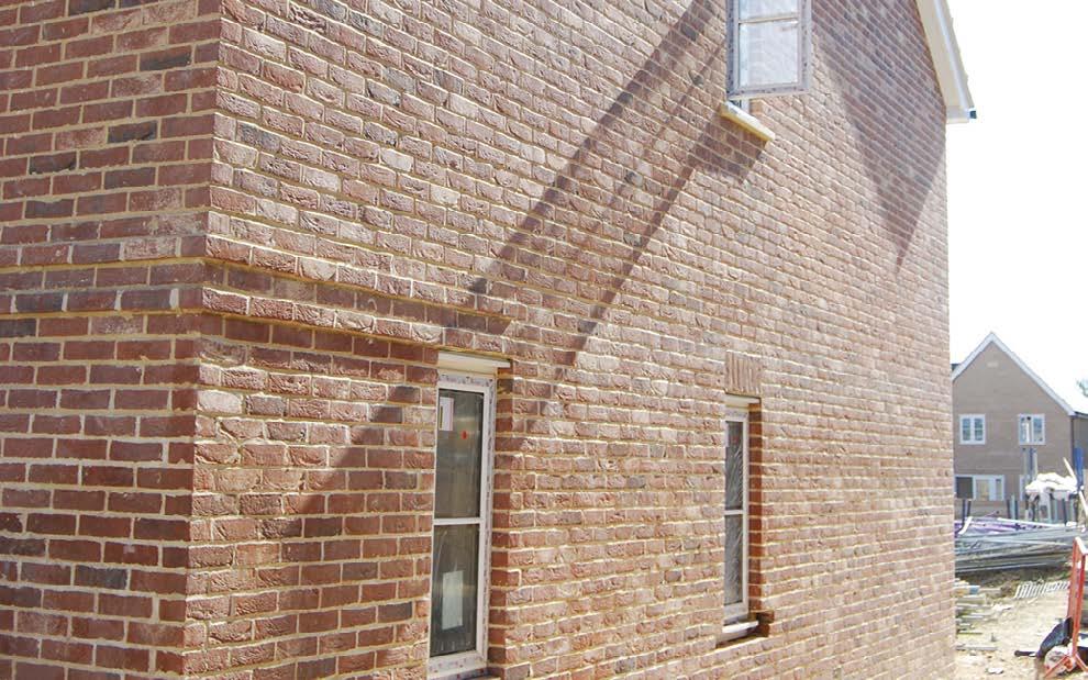
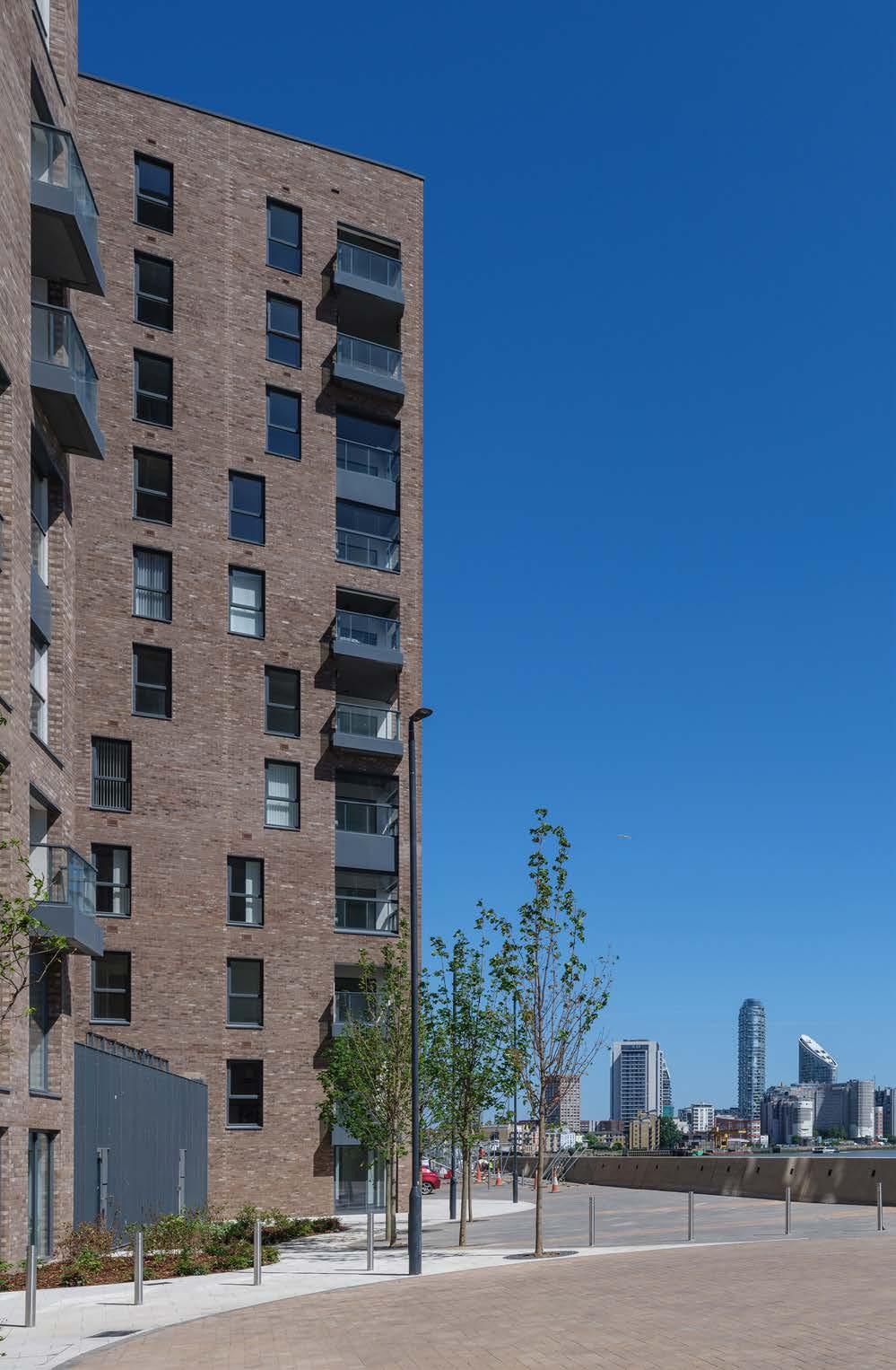
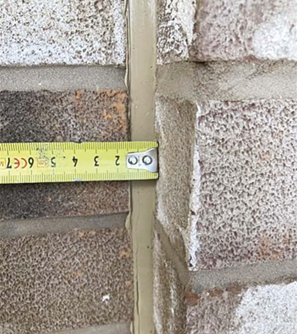
Examples of well-blended consistent brickwork with straight vertical movement joints of consistent width.
Care taken to install this intumescent open state horizontal fire barrier at the compartment floor location behind a rainscreen cladding system.
Internal Masonry Walls
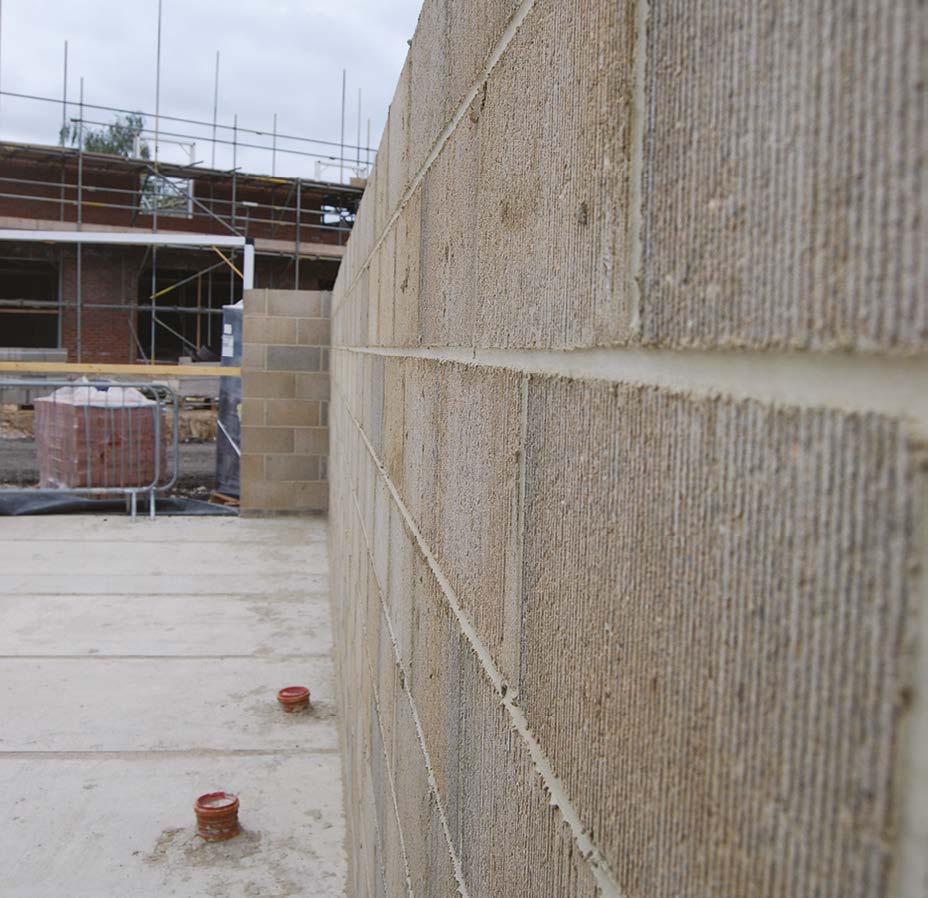
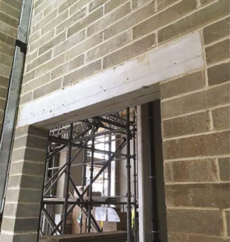
This internal blockwork will ultimately be covered with plaster and wall finishes; however pride has been taken to present the blockwork to a very high standard, with all joints fully filled and jointed.
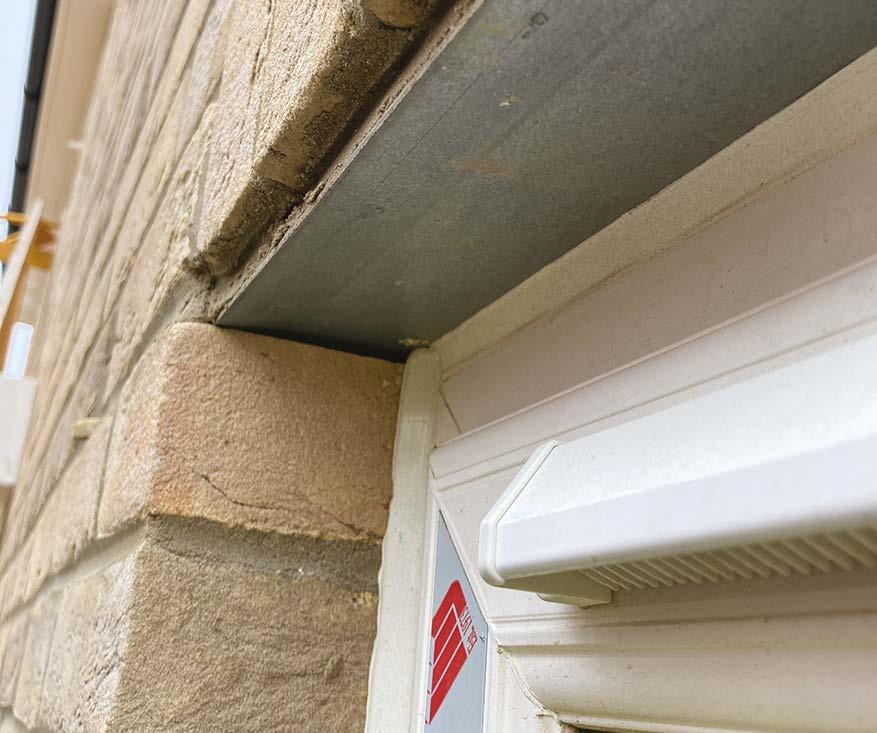
Neat work, coursed correctly to provide the lintel bearing onto a full masonry unit.
9. Superstructures
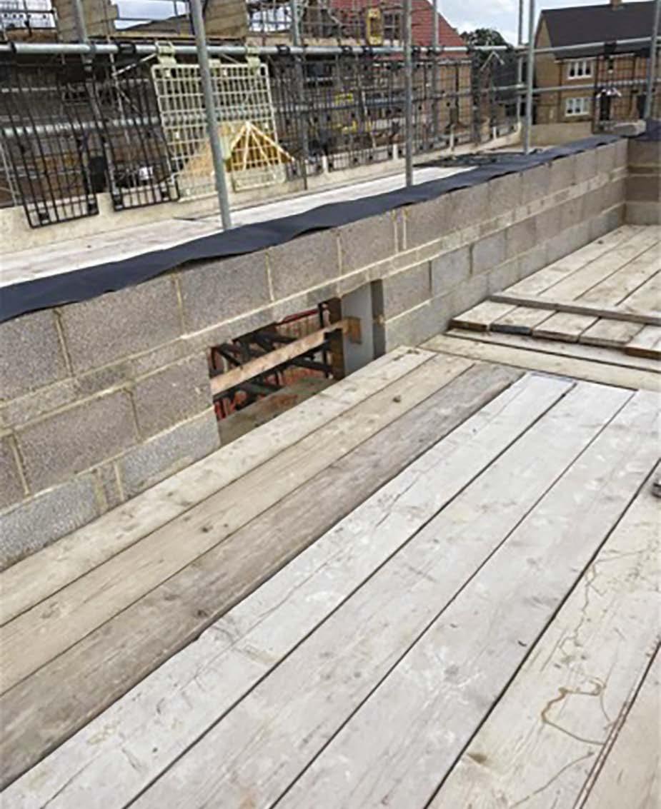
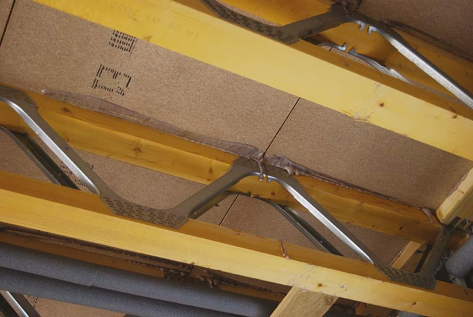
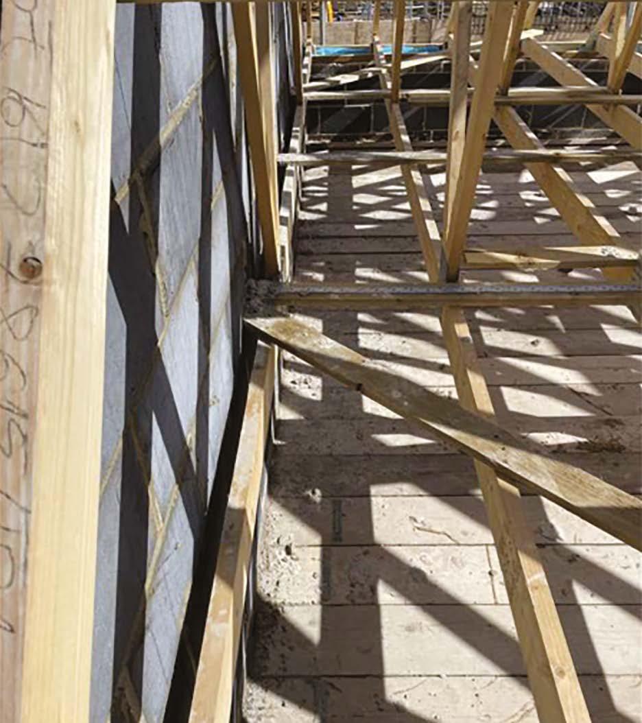
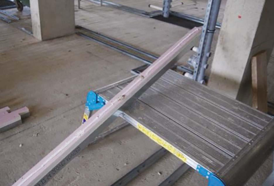
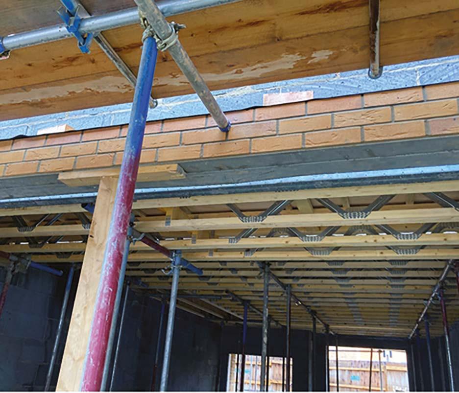
Timber Upper Floors
A 10mm minimum clearance gap is maintained between the floor decking and the walls.
The stairwell is temporarily decked over to provide a safe working platform.
Decking boards are staggered and fully glued to all joints and to the joists below. These are then screwed whilst the glue is wet and screw heads sealed with adhesive.
Lateral bracing should be installed in accordance with the floor manufacturer’s design, the timber should be fixed tight to the external wall to provide lateral support with a suitable metal strap taken into the cavity and tightly abutting the inner wall leaf.
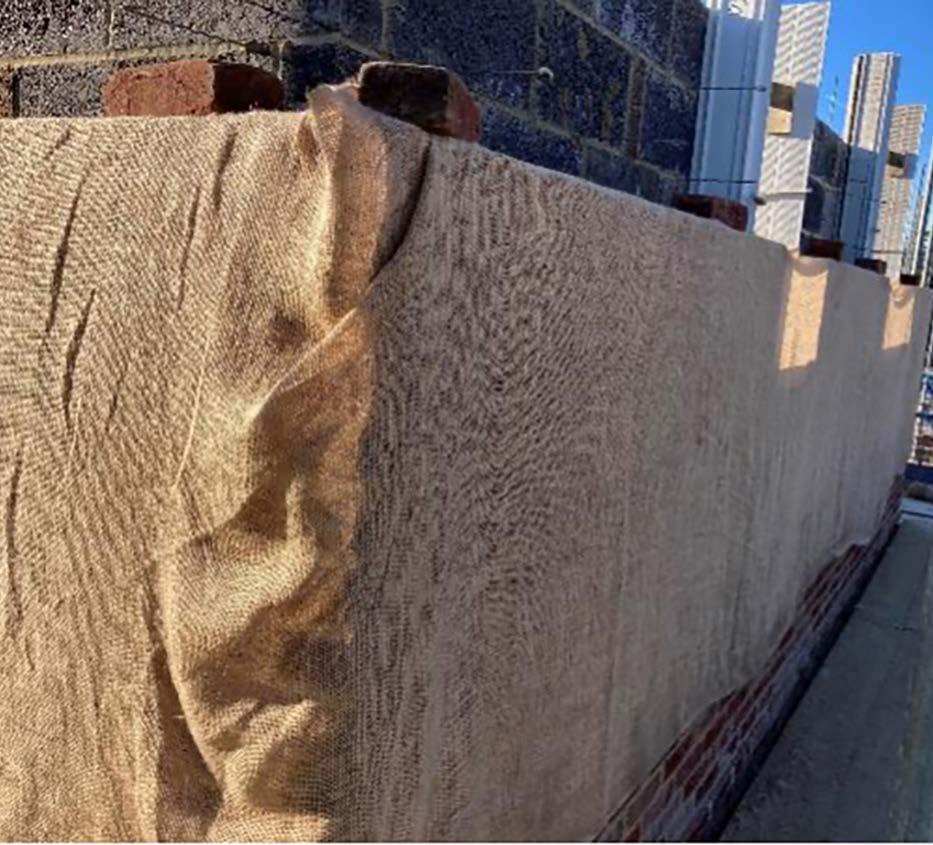
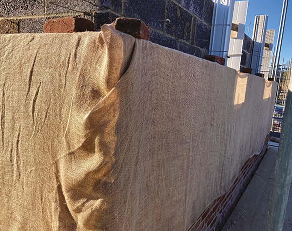
Face brickwork protected from cold weather using hessian sheets.
Adhesive should be visible from below.
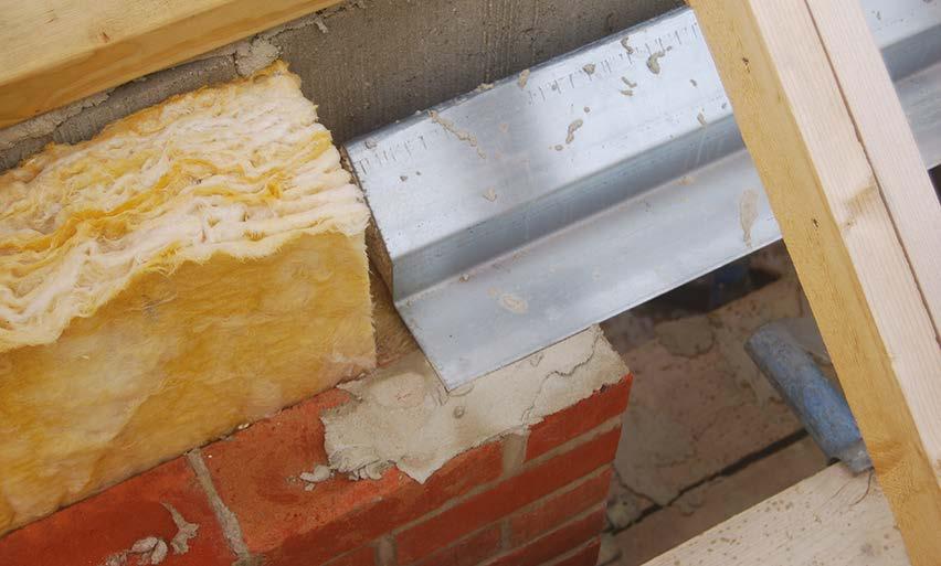
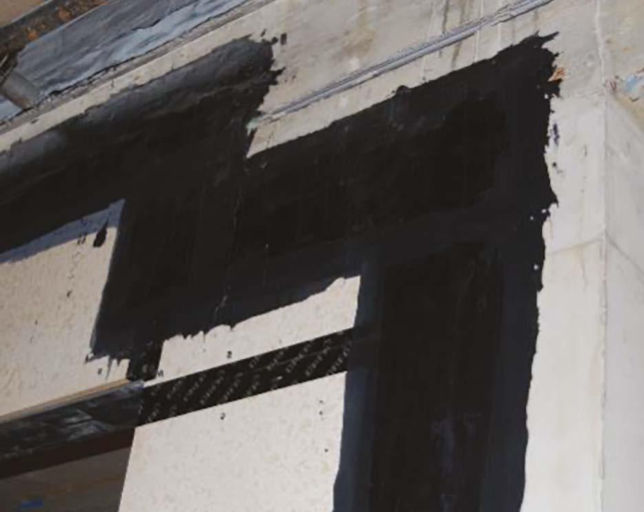
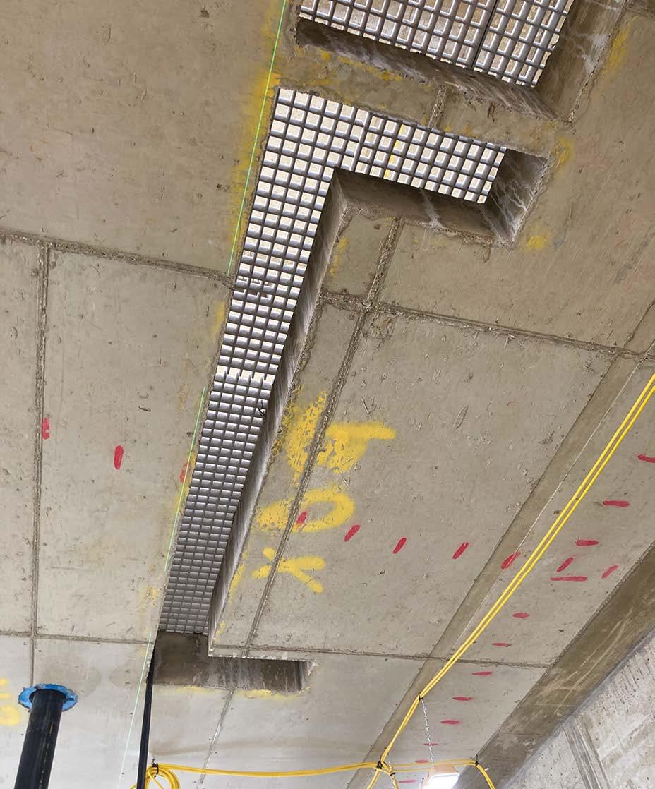
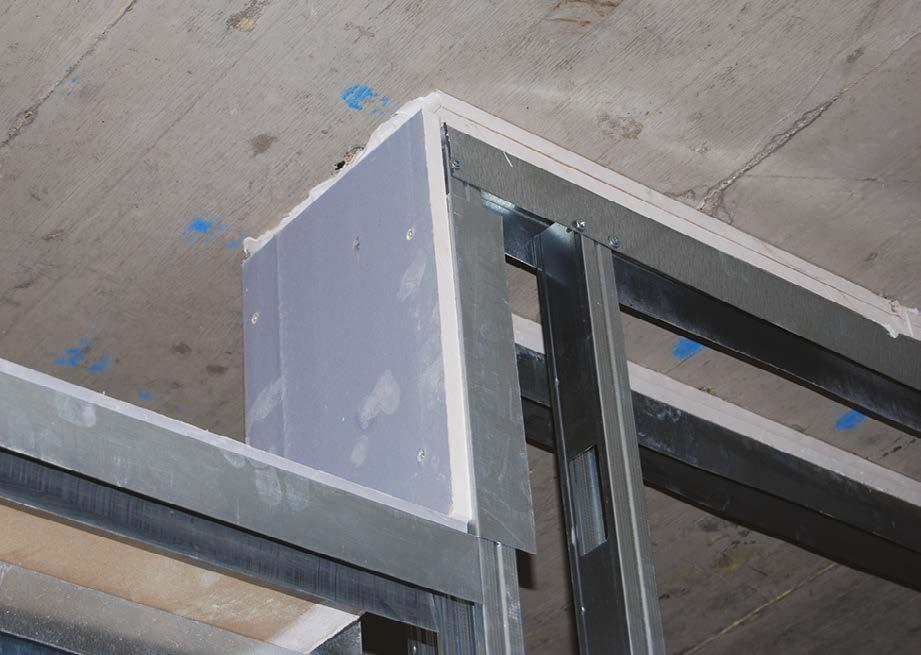
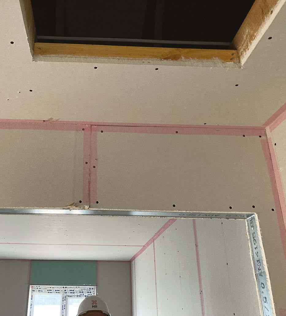
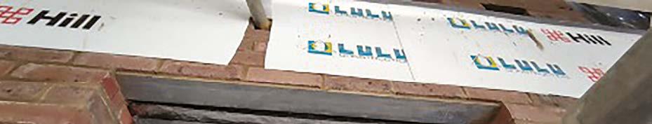
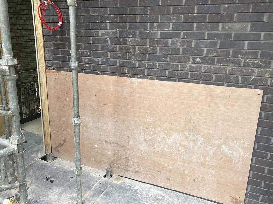
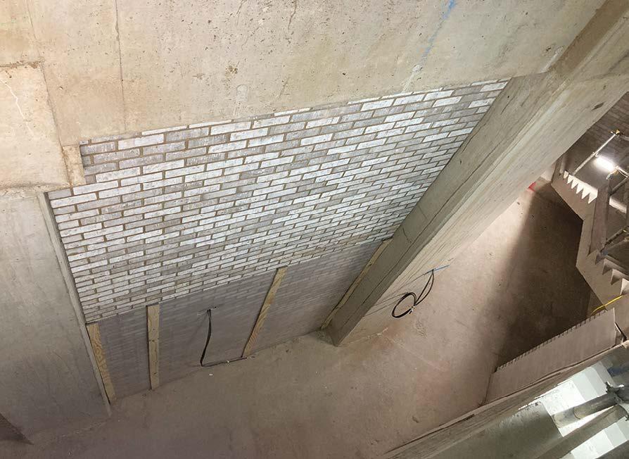
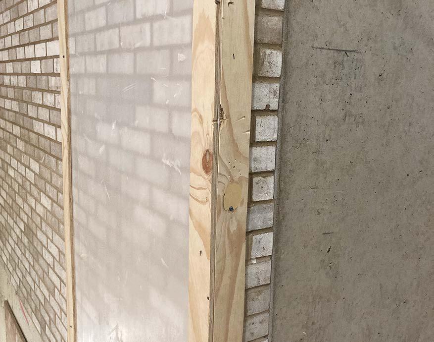
Reinformed concrete structures are not included within this guidance document, however one issue that required careful consideration is the location of service riser openings incorporating GRP grillage. It is important that the face of the concrete opening does not recess below any part of any plasterboard fire-rated wall, as this will compromise the performance of the wall if the sole plate is not fully protected by all layers of plasterboard within the wall build up.
In this image, the fire partition overhangs the riser opening and the metal has no protection from the effects of fire. This is not an acceptable construction.
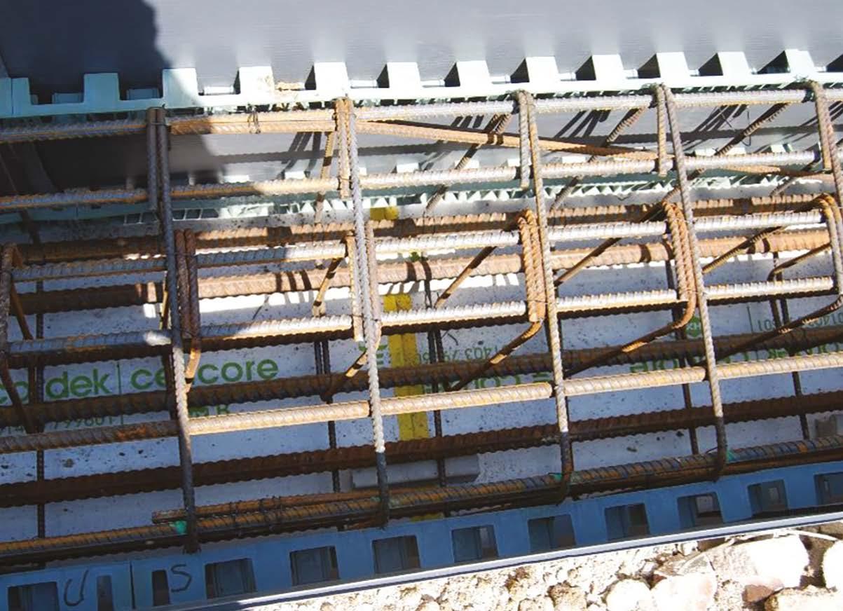
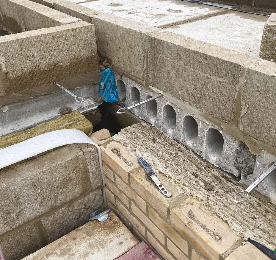
Pre-cast concrete plank floors – considerations
y Ensure that the concrete planks align with the inner face of the cavity wall to prevent bridging of the cavity, (including reduced thermal insulation thickness where this may occur).
y Where the pre-cast planks coincide with cavity fire barriers, the voids should be filled to maintain a solid floor width contact with the barrier material.
y Care should be taken to ensure that suitable bearing is provided to the PCC planks, particularly where these include three-sided service openings. If in doubt, refer any concerns to the structural engineer.
y Consideration should be given to PCC camber and its potential impact on screed thicknesses or the initial coursing / bedding of masonry walls that occur mid span.
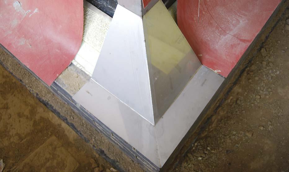
An example of service riser openings with cast in GRP safety grillage.
In this image the PCC planks should have their hollow cores filled to provide a full abutment face for the fire barrier.
10. Roofs
Roofs perform a critical function in keeping a building watertight. The primary requirement of any roof structure is to keep the rain out of the building. Year on year, new home warranty providers report the single highest area of claim relates to roof failures; any weakness in relation to quality will almost certainly result in a roof failure.
The roof may also provide structural support to the walls and floors of the building and prevents the passage of smoke or flame between buildings or through fire compartments. Subject to the height of the building and specific detailing, the construction of the roof, including insulation material, may be subject to restrictions on fire performance to prevent external fire spread.
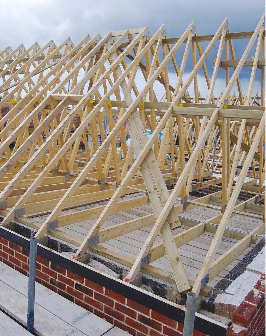
Pitched Roofs (a roof angle between 10° – 70°)
Structure
Concrete roof tiles weigh approximately 46kg/m2, so the overall weight of a fully-tiled roof can be many tens of tonnes or even hundreds of tonnes on large roofs. It is crucial, therefore, that the roof structure is sound to safely transfer this load through the loadbearing structure of the building.
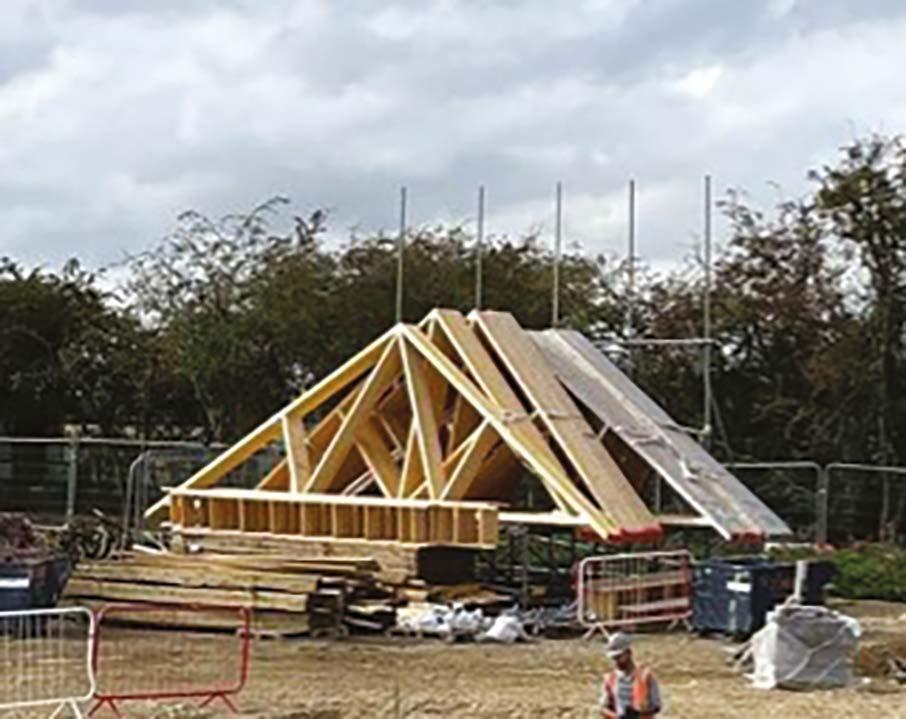
There are two types of pitched roof: a traditional cut roof, using structural grade timber cut and constructed on site by a carpenter or a truss rafter roof, using factory manufactured truss rafters (or a combination of both types). All roof structures must be designed by a structural engineer.
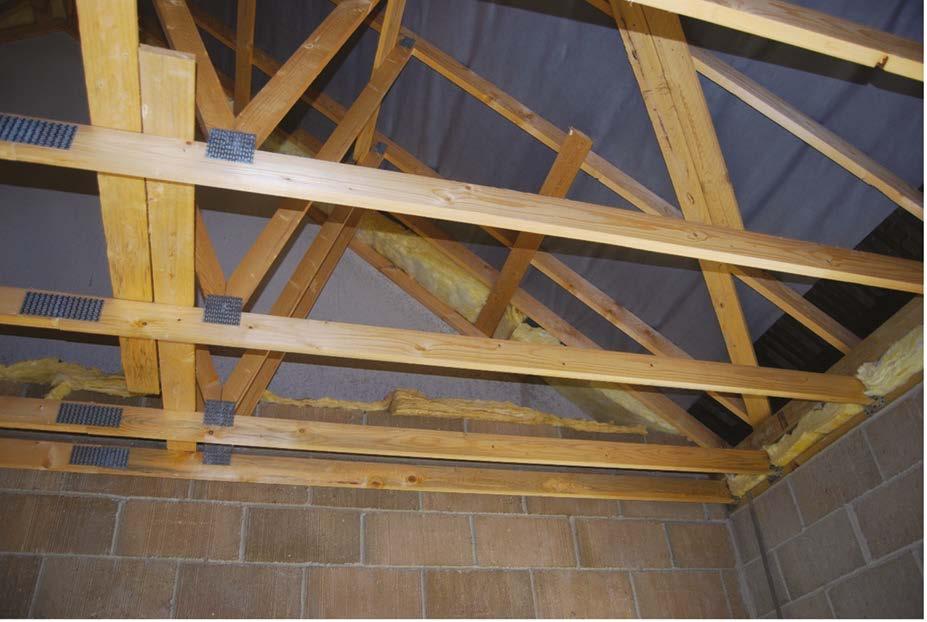
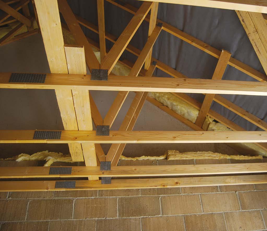
Terminology:
y Rafter: carries the weight of the roof finish (e.g. tiles) and provides fixing for underlay and battens.
y Ceiling joist or tie: triangulates the rafters, stopping the walls and roof spreading outwards. Also supports the loft insulation and ceiling boards and loft access boards and platforms.
y Ridge: provides fixing and spacing for the tops of the rafters or trusses.
y Purlin: supports long span rafters to prevent deflection and increase stiffness. These are typically timber or structural steel.
y Struts: give support to purlins to prevent deflection and transmit roof loading to the structure below.
y Collar: ties the roof together at purlin level.
y Ceiling binders and hangers: supports long span ceiling joists.
y Pole plates: similar to purlins but used where ceiling joists are above wall plate level.
Ridge Collar Strut
Purlin
Hanger
Wall plate Binder
Pole
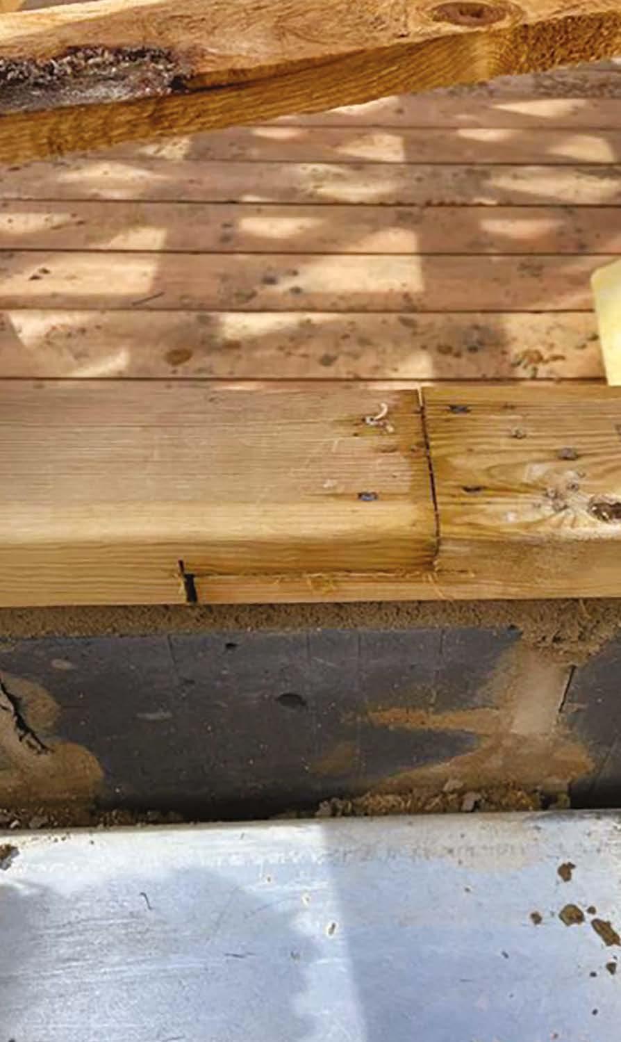
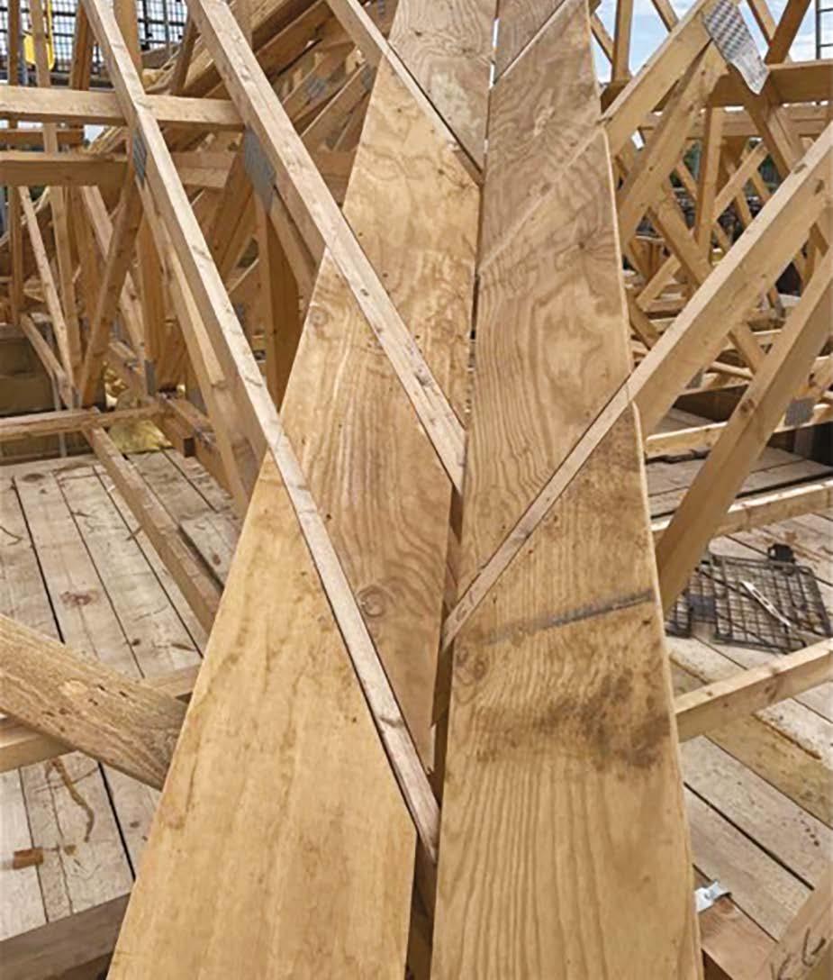
Where rafters are birdsmouthed over wall plates, these must never be cut more than 1/3 the overall depth (d) of the rafter member.
In this example of poor workmanship, the carpenter has used a circular saw and overcut the joint. If circular saws are used to cut the birdsmouth, this should be completed using a hand saw.
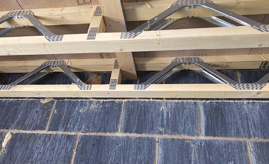
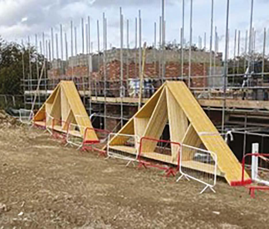
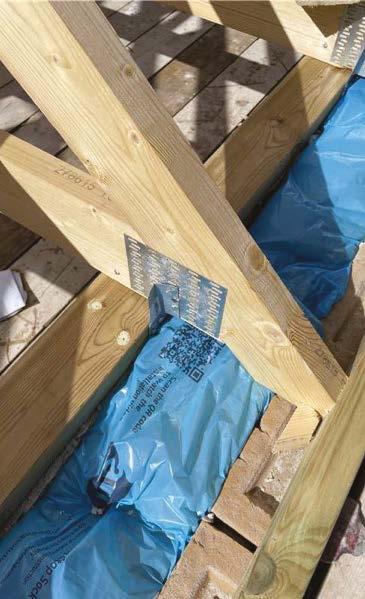
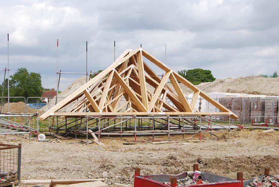
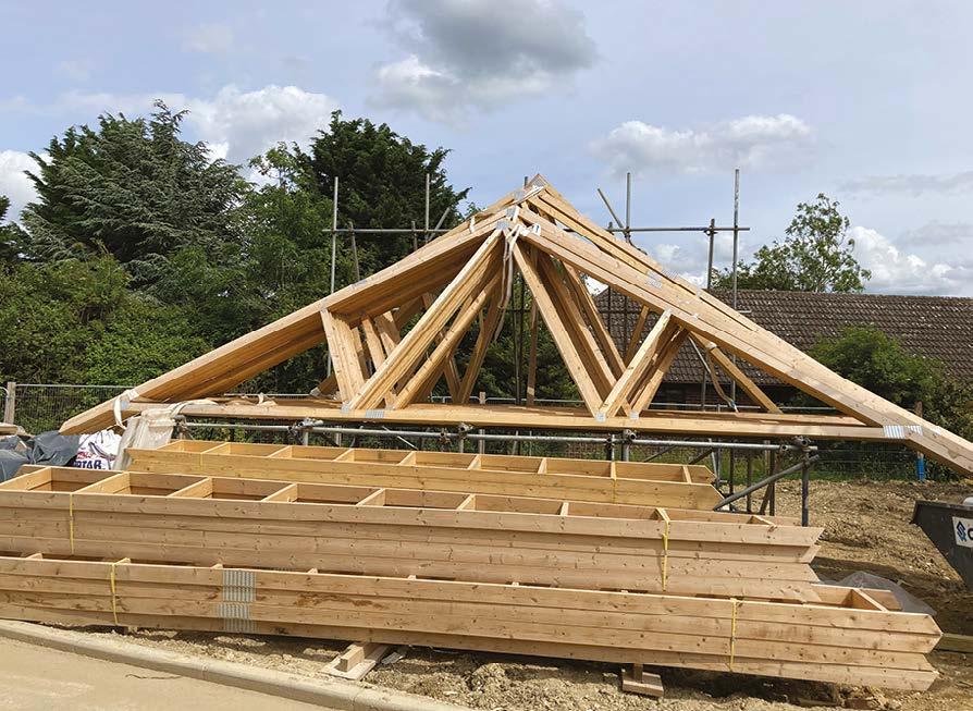
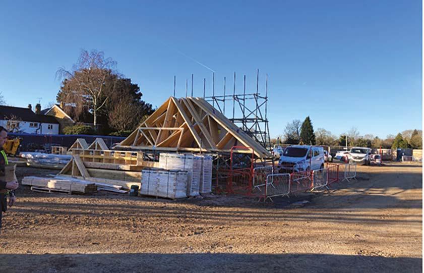
The most common type of roof in new domestic buildings is trussed rafter roof. These are of a lighter weight construction that a traditional cut roof as they gain their strength on being a triangulated frame with strong truss plate connectors.
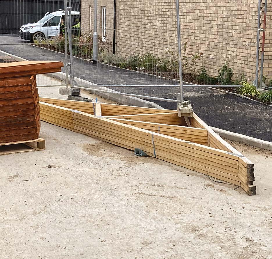
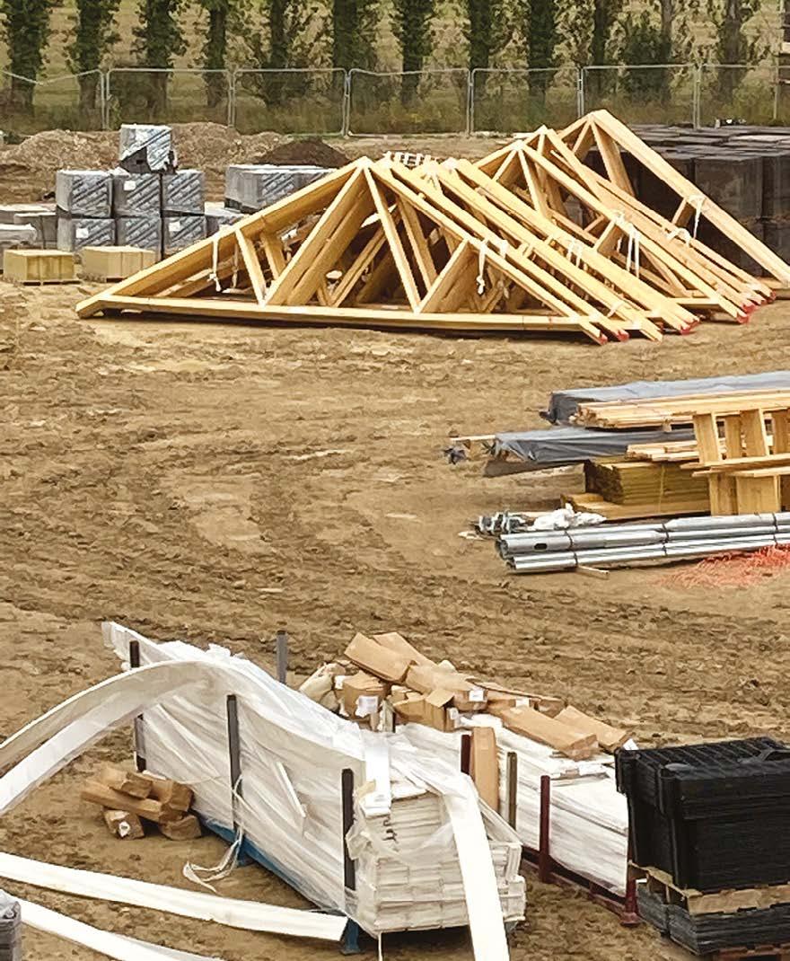
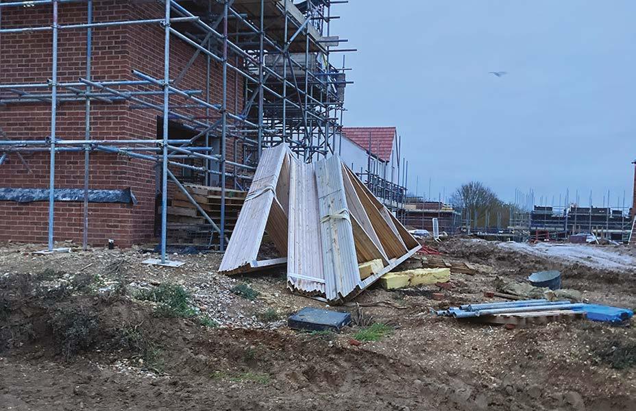
Being of smaller section size, care must be taken when storing and transporting them to prevent damage.
Roof trusses stored off the ground on a scaffold truss rack.
Incorrect truss storage
Continuous binder
10. Roofs
Continuous binder
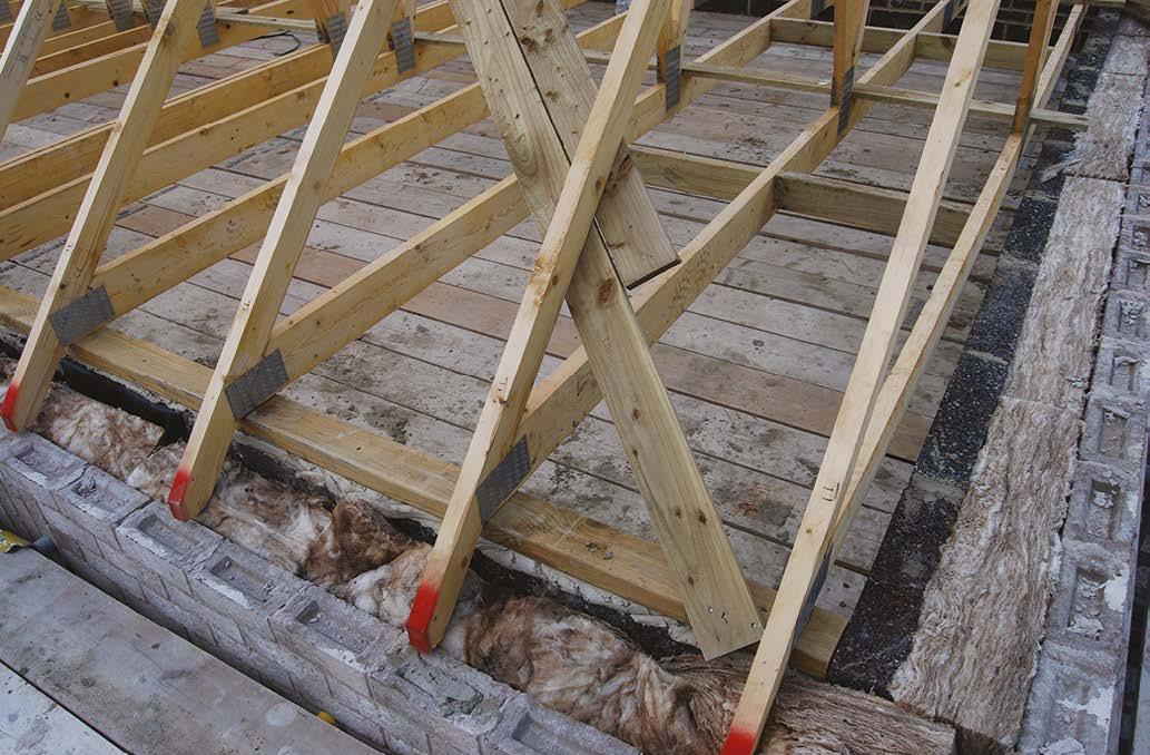
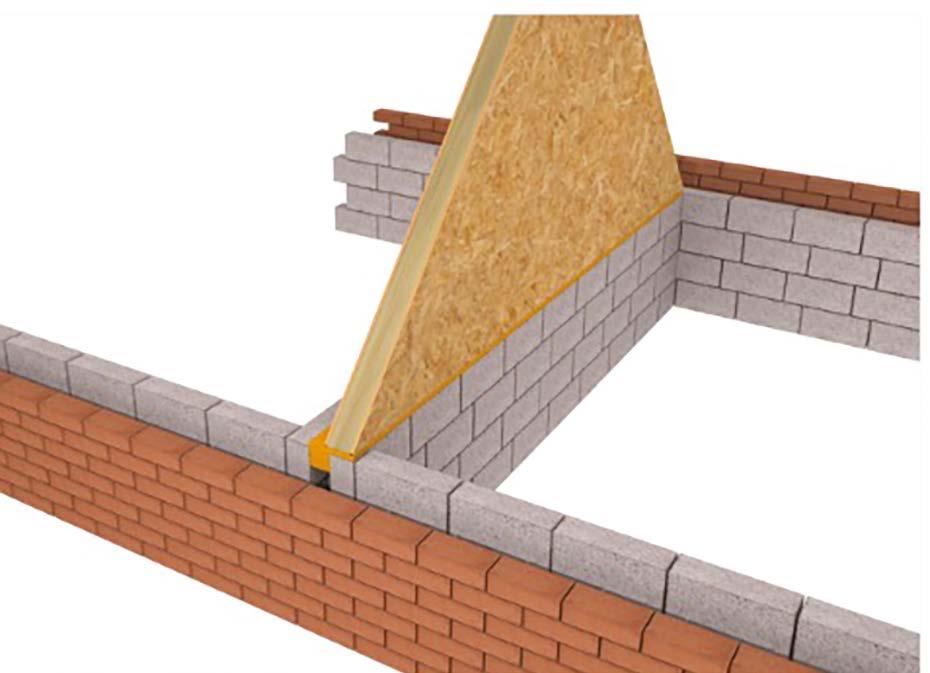
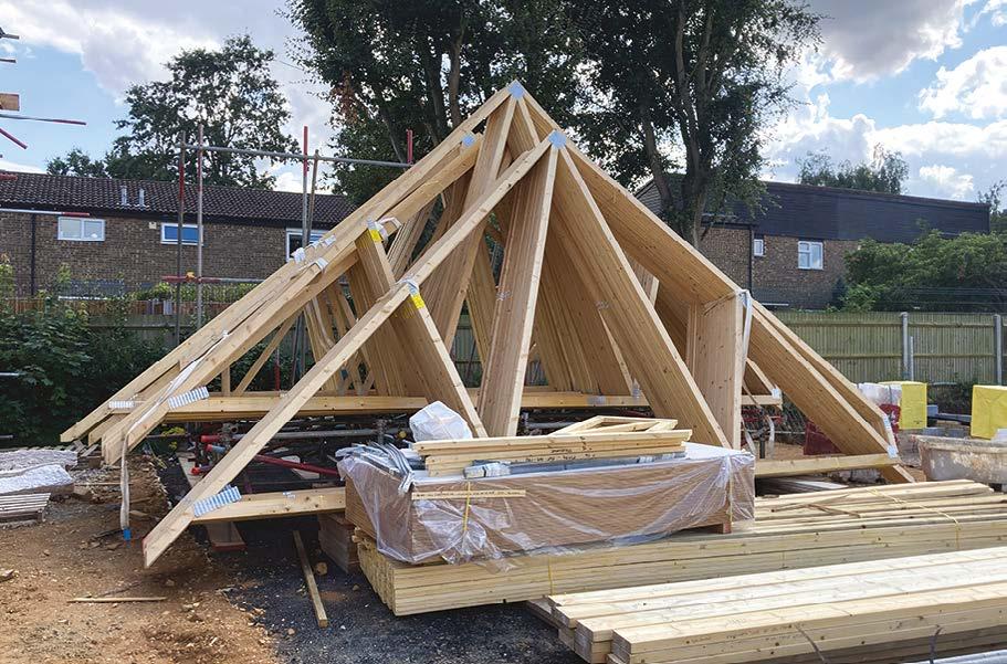
Trussed roofs incorporating valleys are typically formed from diminishing trusses. Diminishing trusses should be supported on splayed bearers or a proprietary truss support bracket.
The maximum distance a trussed rafter can project over a wall plate is as noted below:
tie
underneath the 25x100m longitudinal bracing (or an additional timber member) fixe minimum of eight screws
Max. projection= whichever is larger
Plywood angle tie prevents wall plates spreading Steel tie prevents spread of hip rafter
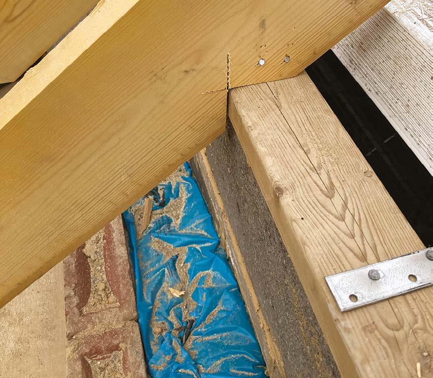
Wall plates are required to secure and evenly spread load from rafters or trusses onto the walls. They should be:
y Bedded to a line and level using nails or straps to hold them down.
y Not less than 3m length (generally) and should extend over a minimum of 3 joists / rafters or trusses.
y Jointed using half-lap joints at corners and running lengths.
y Where specified, have holding down straps a minimum of 1m long with a cross section of 30mm x 2.5mm fixed at a maximum of 2m centres.
y Where into masonry, a minimum of four number, 50mm long no. 12 wood screws (into suitable plugs).
y Provided so that the lowest fixing is within 150mm from the bottom of the strap.
Timber angle tie prevents wall plates spreading
Dragon tie prevents spread of hip rafter
Rafter
Ceiling
In these images, the wall plate is correctly bedded on mortar (circa 10mm bed thickness) with a cross-halving joint where wall plates are joined.
Max. projection= whichever is larger
In this first image above, an additional timber has been fixed to the wall plate to provide a secure fixing for the diagonal roof bracing.
Triangulation: Angle ties should be used on hipped-roof corners to prevent the wall plates spreading. For heavily-loaded hip rafters, dragon ties or similar bracing should be used to prevent hip rafter spread.
Timber angle tie prevents wall plates spreading Dragon tie prevents spread of hip rafter
angle tie prevents wall plates spreading Dragon tie prevents spread of hip rafter
angle tie prevents wall plates spreading Steel tie prevents spread of hip rafter
Rafter
Ceiling tie
Timber
Strap underneath solid noggings,
Bracing fitted
Strap underneath the 25x100mm
Rafter
Plywood
Strap underneath solid noggings,
Bracing fitted
Strap underneath the 25x100mm
10. Roofs
Continuous binder
Lateral restraint straps must be installed to all gables.
y For homes up to and including 3 storeys – 2m centres
y For homes above 3 storeys – 1.25m centres.
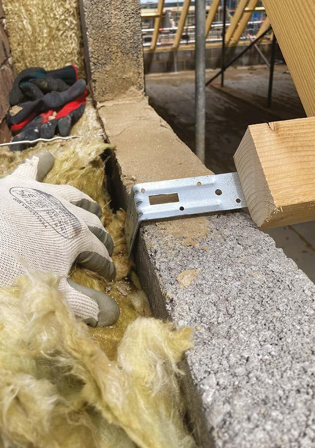
They must be fixed one of two ways (as follows) and fitted tight to the inner leaf of the cavity wall and turned down across a substantial piece of masonry.
1. Fixing to solid noggings using a minimum of four 50mm x 4mm steel screws or four 75mm x 4mm (8SWG) round nails, with one fixing in the third rafter (Figure 15)
Timber angle tie prevents wall plates spreading Dragon tie prevents spread of hip rafter
Timber angle tie prevents wall plates spreading Dragon tie prevents spread of hip rafter Plywood tie prevents wall plates spreadin Steel prevents spread hip rafte
Strap underneath solid noggings, fixed with a minimum of four fixings (at least one in the third rafter)
Strap underneath solid noggings, fixed with a minimum of four fixings (at least one in the third rafter)
Block removed for clarity
Packing between rafter and wall
Strap held tightly against block inner leaf
Block removed for clarity
Nogging fixed horizontally to avoid twisting the restraint strap
Packing between rafter and wall
Strap held tightly against block inner leaf
Nogging fixed horizontally to avoid twisting the restraint strap
Strap underneath the 25x100mm longitudinal bracing (or an additional timber member) fixed with a minimum of eight screws
2. Fixing to longitudinal bracing members using eight 25mm x 4mm steel screws evenly distributed along the length of the strap (Figure 16). Alternatively, 100mm x 25mm timber members, fixed over four trusses and nailed in accordance with Clause 7.2.9 can be used where the position of the strap does not coincide with a longitudinal binder.
Strap underneath the 25x100mm longitudinal bracing (or an additional timber member) fixed with a minimum of eight screws
Bracing fitted tightly to internal face of block inner leaf
Bracing fitted tightly to internal face of block inner leaf
Strap held tightly against block inner leaf
Strap held tightly against block inner leaf
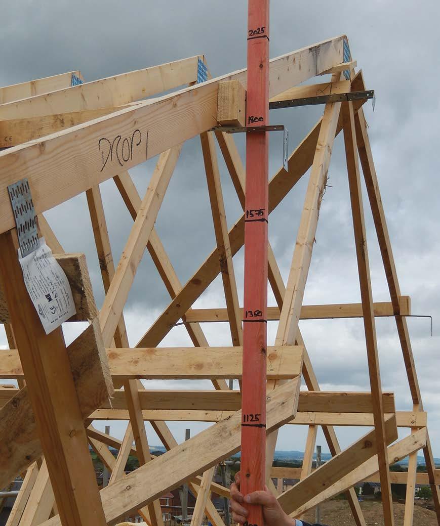
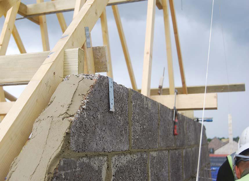
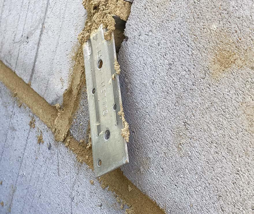
Very good practice has been adopted here. A gauge rod is used to accurately set out the location of the straps, ensuring that it sits within the block bed joint and laps over substantial block.
example
The strap must be in full contact with a substantial block element. In this example, it has been set out perfectly to suit block coursing.
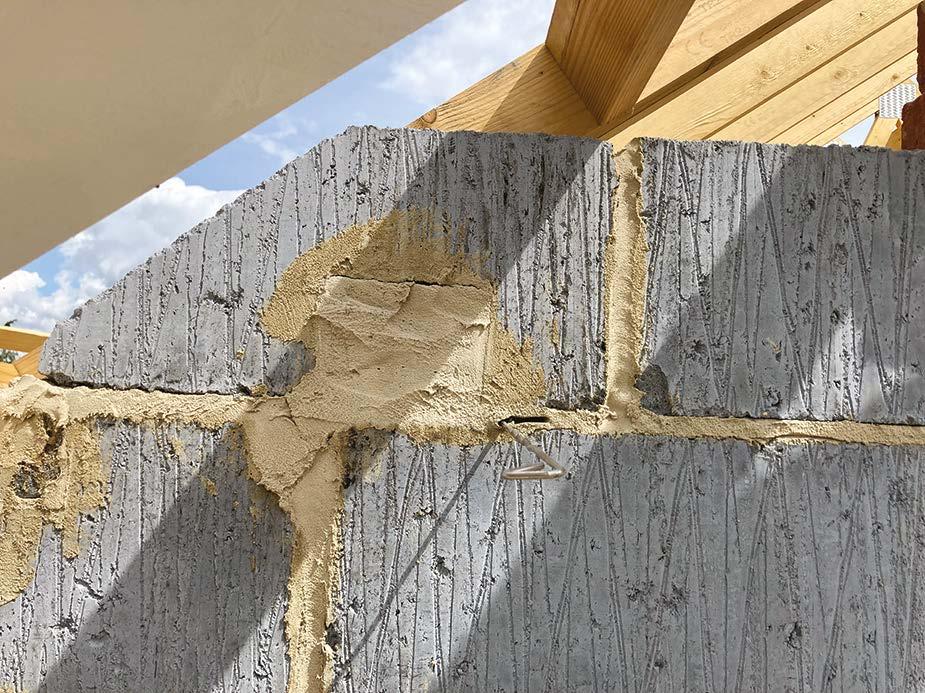
Here are some examples of poor quality.
This strap is not in contact with the block wall and therefore offers no lateral support.
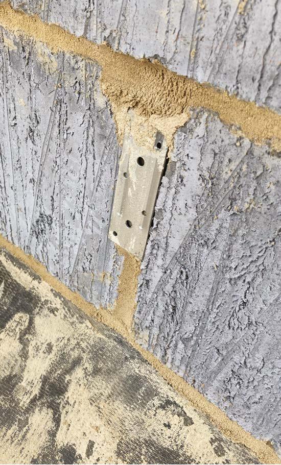
In this image, the strap is buried within this large section of mortar. The mortar is liable to crack, and the strap will offer limited or zero restraint to the gable wall.
A good
of fixing straps using the ‘noggin’ method.
10. Roofs
Bracing required for trussed rafter roofs.
y All bracing to roofs should be a minimum of 100mm x 25mm timber (3mm tolerance applies).
y Nailed twice to each rafter it crosses; fixings should be 3.35mm x 65mm (10 gauge) galvanized round wire nails or minimum 3.1mm x 75mm mechanically-driven gun nails.
y Where braces and binders are not continuous, they should be lap-jointed and nailed to a minimum of two trusses.
Diagonal bracing:
y Diagonal and longitudinal bracing should be provided at rafter level.
y Diagonal and chevron bracing should pass across each rafter in the roof, however, small gaps, such as two trussed rafters between sets of bracing, or one trussed rafter adjacent to gable or separating walls, is permitted in the middle of an otherwise fully-braced roof.
y There should be a minimum of four diagonal rafter braces in each roof; in narrow-fronted roofs and mono-pitched roofs, where the braces cross, the intersection detail should be used as noted in NHBC Standards Chapter 7.2.
y The diagonal bracing should extend over and be directly fixed to the wall plate, fixings should be 3.35mm x 65mm (10 gauge) galvanized round wire nails or minimum 3.1mm x 75mm mechanically-driven gun nails.
Longitudinal bracing members should extend the full length of the roof, tightly abut gable and party walls and permit diagonal bracing to pass (they may be lapjointed providing the overlap is nailed to a minimum of two trussed rafters).
Technical images source: nhbc-standards.co.uk
Binders abutted tightly against gable and separating walls
Binders fixed to ceiling ties of trussed rafters, where necessary using two lap-jointed lengths
Binders abutted tightly against gable and separating walls
Binders fixed to ceiling ties of trussed rafters, where necessary using two lap-jointed lengths
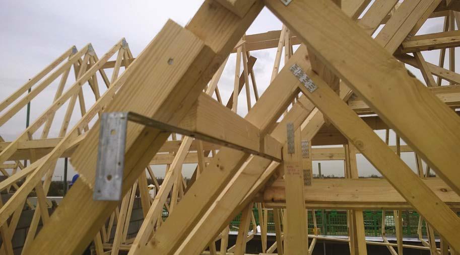
Longitudinal bracing installed tight to the gable wall. Restraint straps installed to the ceiling joists and diagonal bracing secure up to the gable wall.
Restraint straps fixed to timber spanning 4 rafters. Lateral and diagonal bracing fully installed and correctly lapped over a minimum of two trusses.
Vally boards are carefully cut and installed to fully support the GRP valley tray.
Diagonal bracing securely fixed to the wall plate and neatly trimmed.
10. Roofs
Pitched roof coverings
Things to look for:
y The roof underlay, tiles, gauge and method of fixing are all specified in a manufacturer’s fixing schedule taking into consideration the location and design of the roof in question.
y Roof underlays must be suitably lapped (and sealed where specified by the roof system manufacturer) at batten locations. These must be undamaged and neatly cut around penetrations using the ‘inverted T’ method or in accordance with instructions for proprietary roof terminals.
y A suitable pre-formed eaves tray and UV resistant underlay is required over fascias at eaves locations.
y Fascia heights should be carefully coordinated between the roofer and carpenter as this height is determined by the pitch of the roof and type of roof covering applied. Fascia boards fixed at the incorrect height will cause the roof to drop or rise up at the eaves, causing potential for water ingress through open lap joints (dropped tiles) or insufficient lap length on shallow pitch areas (raised tiles).
y Roof battens should be of a BS:5534 structural grade timber with staggered joints, spanning a min of 4 rafters (where possible).
y Cut battens should be treated with a siteapplied timber preservative, in a contrasting colour to that of the batten.
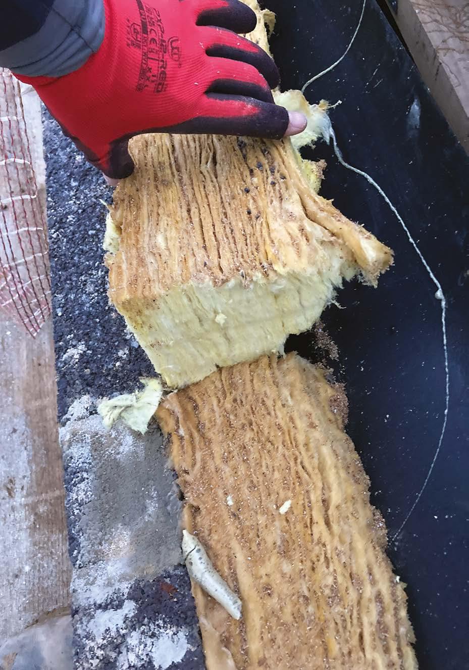
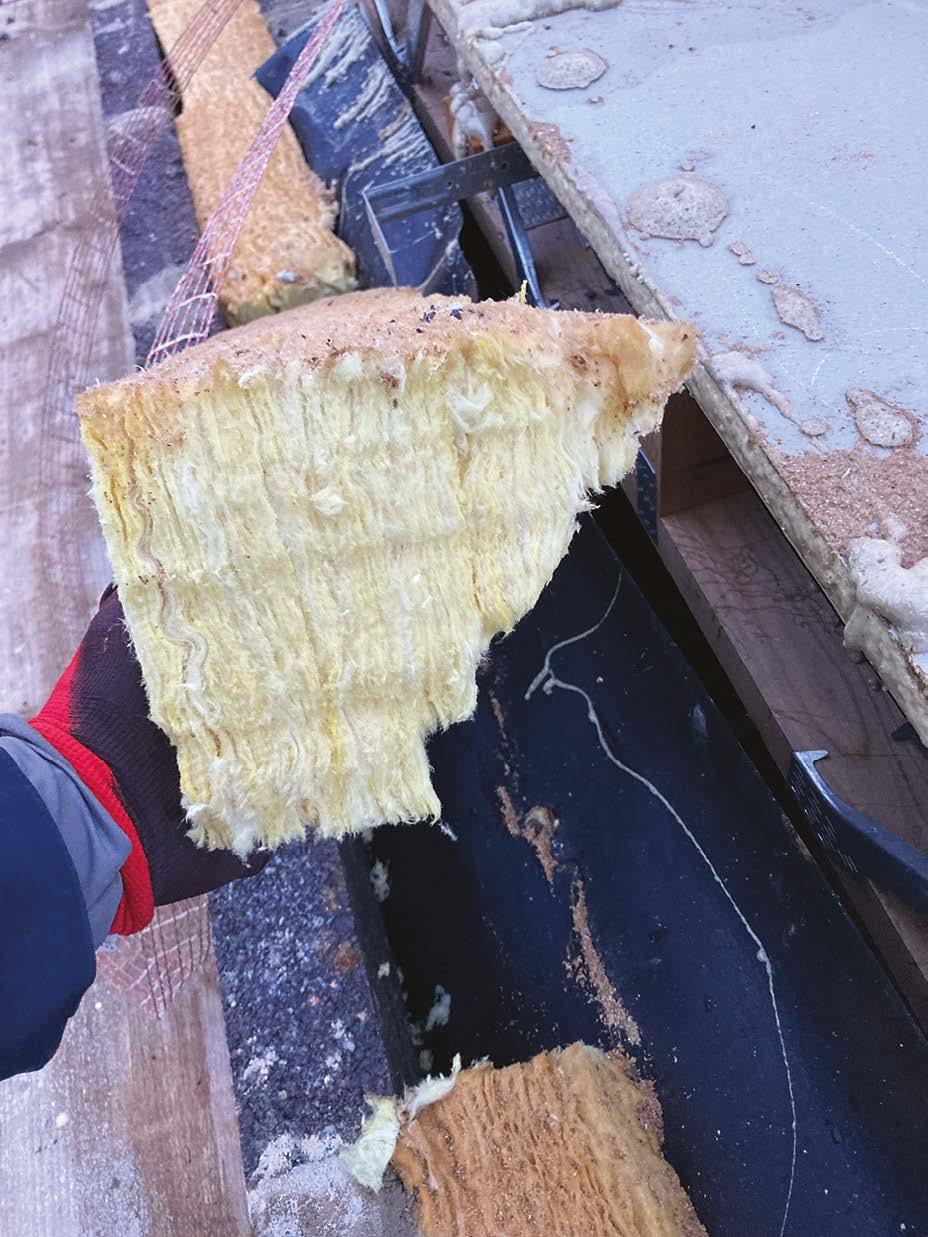
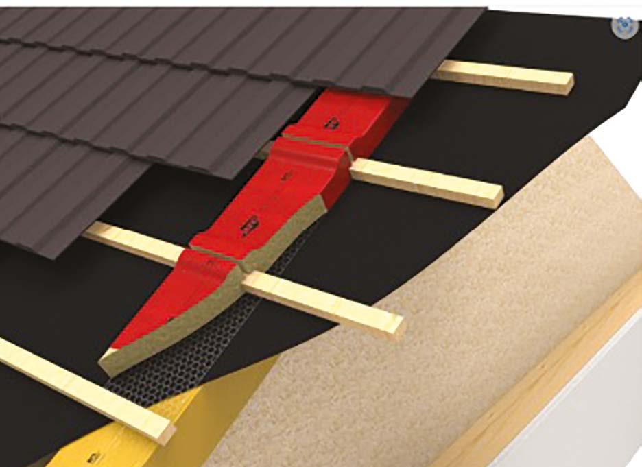
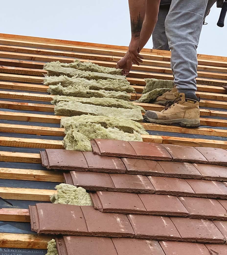
y The space between the battens should be fire sealed using stone wool wherever roofs cross compartment walls.
y Verges to gables should be formed using proprietary verge systems or wet bedded onto 100mm of roofing mortar.
y All tiles should be twice fixed plus any additional tile clips specified by the roof manufacturer.
y Abutments with plain tiles require code 3 lead soakers (double-lapped tiles) or proprietary abutment gutter trays. Code 4 lead flashing is required to dress over this.
y All leadwork (flashings, trays, valleys, saddles etc) must be treated immediately on completion of the work, with patination oil. Leadwork should be installed in accordance with the Lead Sheet Association publication: Rolled Lead Sheet, The Complete Manual.
y Where rolled, single-lapped tiles are used, providing the flashing discharges into the ‘trough’ of the tile, a gutter is not required.
y Ridge and hip tiles to the main roof must be mechanically fixed. End tiles must be twice fixed to prevent uplift, and where required to be cut, should be spread over a number of tiles to avoid small cuts at the exposed roof ends.
y Roofs should be gauged to ensure that the minimum head lap specified by the manufacturer for the location and pitch of roof is maintained and discharge over the centre line of the eaves gutter.
y Roof vents should be set out to offer the shortest possible run within the loft area and, where possible, discharge to the rear facing elevation.
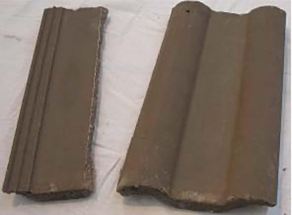
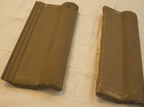
Single or double-lapped tiles?
Double-lapped tiles, rely on a combination of three overlapping tiles to create a watertight roof. They are typically available in 1/2, full and 1 1/2 tile sizes and can be cut, making them very suitable for complex roofs.
The headlap is measured across alternate tiles where they are double lapped as seen below:
Double-lapped tile terminology
Single-lapped tiles are well suited to large simple roofs. They cannot be cut except at perimeters and are generally unavailable in modules other than full tiles. Where small tiles are unavoidable, they must be bonded to a larger tile using an adhesive approved by the tile manufacturer.
Single-lapped tiles rely on a watertight interlock detail to keep them weathertight. Care must be taken that these are not damaged.
The headlap dimension on single-lapped tiles is measured to the tile immediately below as shown here.
Additional fixings may be specified by the roofing manufacturer in its fixing schedule and these must be installed where required.
Gauge
Gauge
Headlap
Headlap
Eaves course tiles
Sidelap
Tile battens
Top course tiles
Gauge
Gauge
Headlap
Headlap
Eaves course tiles
Tile battens
Batten spacing
Batten spacing = Gauge
Gauge
Headlap
Batten spacing
Batten spacing = Gauge
Gauge
Headlap
Typical eaves tile clip
Typical tile to tile clip
Typical general tile clip
10. Roofs
Roof underlays
Care should be taken not to stretch roof underlays tightly. They should have a 10mm natural sag to transfer any collected water into the gutter and not to the batten-fixing positions. The underlay must not have a sag greater than 10mm or the ‘billowing effect’ may lift the tiles off the roof.
When too tight, water runs to nail holes
Roof battening
In this photograph, roof battens cut correctly so that they do not all fall on the same rafter.
y Batten spacing > 200mm, no more than one batten in any group of four should be joined over any one truss or rafter.
y Batten spacing ≤ 200mm, no more than three joints should be made over any twelve consecutive battens.
The underfelt, however, is stretched too tightly with no sag between the rafters and the joints in the underlay have not lapped under a batten.
Cut ends of roof battens can clearly be seen to have been treated with a brush-applied timber preservative.
Slight Sag
Leadwork
Lead is commonly used in roof flashing and detailing and is generally used on roofing in three standard weights.
Code 3 – soakers
Code 4 - cover flashings
Code 5 – valleys, formers etc.
All lead work should be installed in accordance with the Rolled Lead Sheet: ‘the complete manual’ as published by the Lead Sheet Association.
Dry or wet work
Subject to the specifications of any given project, details such as valleys, hips, ridges or verges may be formed from dry fix proprietary products or using traditional wetbedded mortar.
Where proprietary systems are used, the works must be installed fully in accordance with the manufacturer’s instructions – a copy of which should be made available by the roofing contractor.
1:3 + Mortar Plasticiser
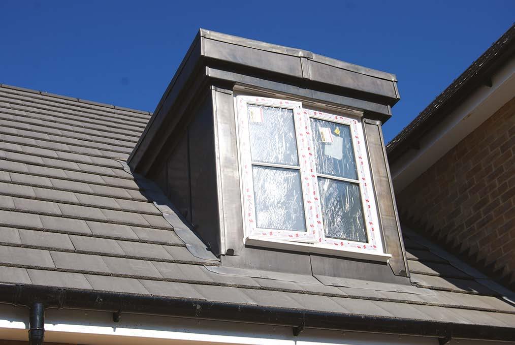
A well-constructed dormer with skilled code 5 leadwork applied. It must be noted that as these are single-lapped tiles, a wall interface gutter is required under the lead cover flashing where the roof abuts the cheeks of the dormer.
Where wet work is specified, mortar must only be as noted below:
Bricklayers mortar or silo mix must NEVER be used on roofs. The soft sand contained within these mortars lacks the tensile strength required, even if additional cement is added.
Roof mortar must be a minimum of 1:3 cement to sand and the sand must contain a minimum of 1/3 sharp sand, plus suitable mortar plasticiser. Alternatively use proprietary mortars specifically designed for roof work.
10. Roofs
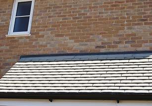
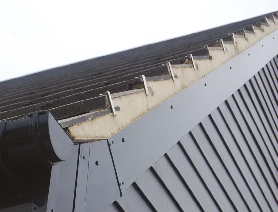
Setting the correct height of the eaves fascia requires consultation and collaboration between the carpenter and rooking contractor, as one size definitely doesn’t fit all.
The correct fascia height ensures that the tiles do not drop or kick up at the eaves location. The height is determined both by the pitch of the roof and also the type of roof covering, with double-lapped tiles typically requiring a higher fascia height to a natural slate, and with a single-lapped tile requiring a fascia height between the two.
Allowance should also be made for any eaves ventilators that may be fixed to the fascia to provide ventilation to the roof.
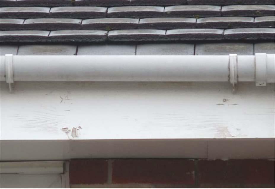
In this photograph, the fascia has been positioned too low, resulting in the last course of tiles dropping and opening up a wide joint that wind and rain may penetrate.
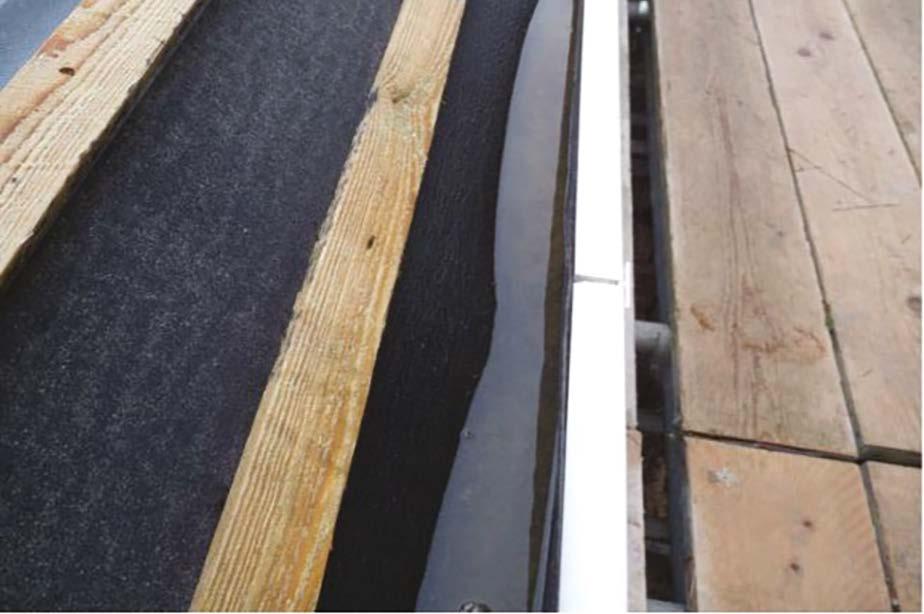
Proprietary UV-resistant eaves boards are now widely used in lieu of tilting fillets, and these should be positioned under the roofing underlay, and discharge into the centre of the gutter. They prevent potential ponding of water on the underlay behind the fascia.
Here is an example of a roof where an eaves tray has not been installed and ponding has occurred. It is only a matter of time before this ponded water gets into the roof.
FASCIA HEIGHTS
Single lap tiles
Natural slate
Double lap tiles
Fascia
Height is inclusive of any fixed eaves vents.
The finished roof covering should be gauged (and hip tiles cut) so that they finish over the centre line of the gutter.
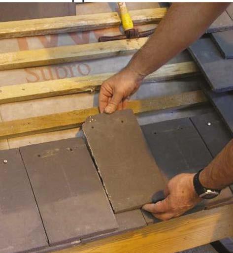
Setting out a roof
It is important that the roof is correctly set out prior to commencement to ensure that minimum headlap / tile gauge and side laps are achieved, as well as correct overhangs to gutters and verges.
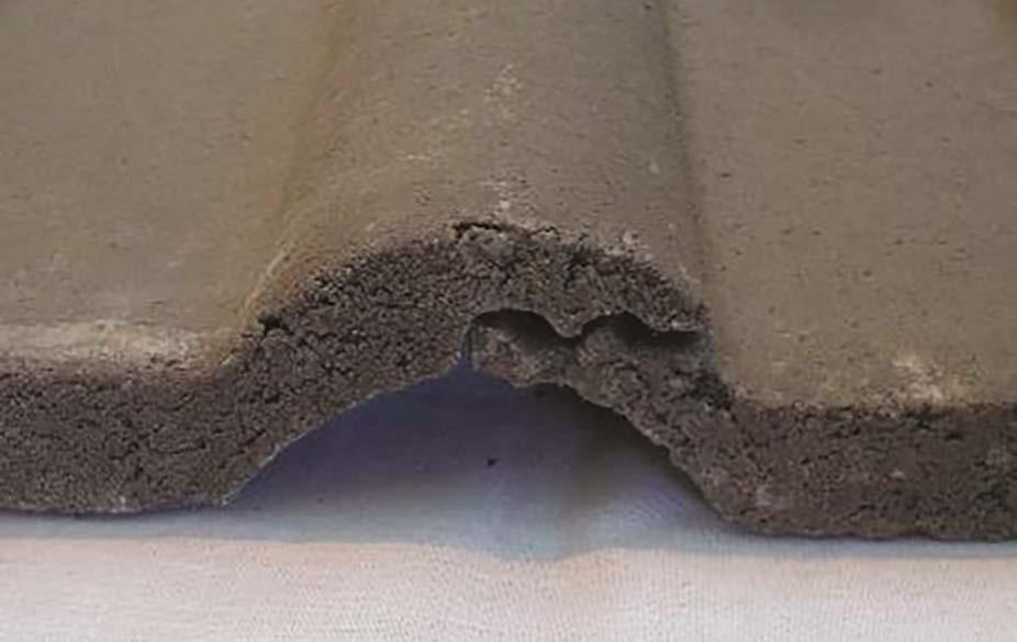
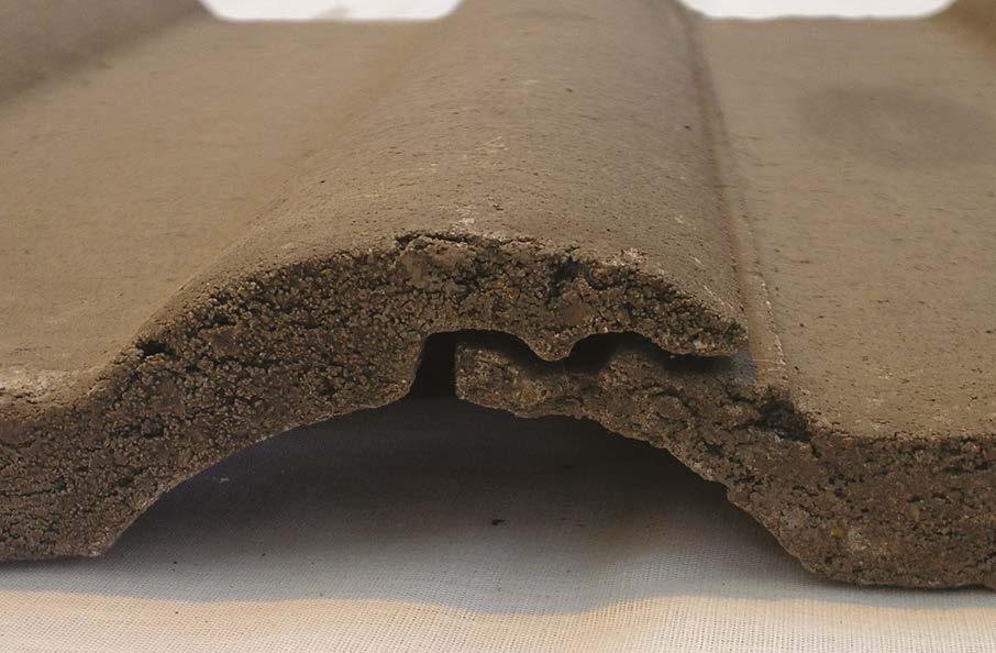
This operation is particularly important when using single-lapped interlocking concrete tiles, as the availability of tiles other than full, standard tiles is very limited. With single-lapped interlocking tiles good practise dictates that vulnerable, cut tiles should always be positioned on the right-hand verge, as this gains the added support of its neighbouring tile that laps over and holds it down, whereas the left-hand verge tiles sit on top of their neighbouring tile.
As interlocking tiles are laid right to left, it is important that this basic setting out is carried out prior to commencement.
Concrete interlocking tiles have something called ‘shunt’ allowing them to be closed-up or opened slightly to assist in eliminating small cuts. Again, this should be checked and set out prior to fixing any tiles.
Interlocking tiles are laid right to left. If roof not set out before tiles laid, the weak cut tile will be on the left
2nd Option
If shunting cannot achieve full tiles achieve minimum 1/2 tile + at verge
1st Option (protected by adjacent tile)
3mm - 4mm shunt per tile (refer tile manufacturer)
10. Roofs
Roof Tile Setting Out
Plain double lapped tiles and slates
Double-lapped tiles and slates are substantially more flexible, as in addition to standard sizes, they are available in 1 1/2 tile modules. They also do not rely on interlocks and so can be cut where required (making sure that minimum side laps are maintained).
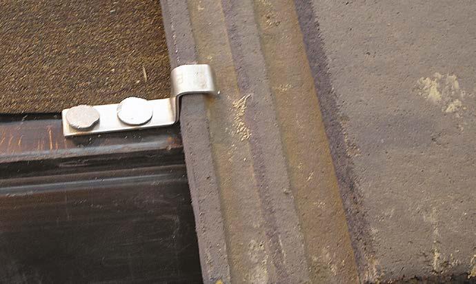
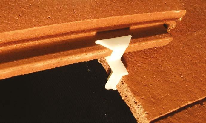
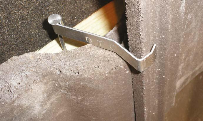
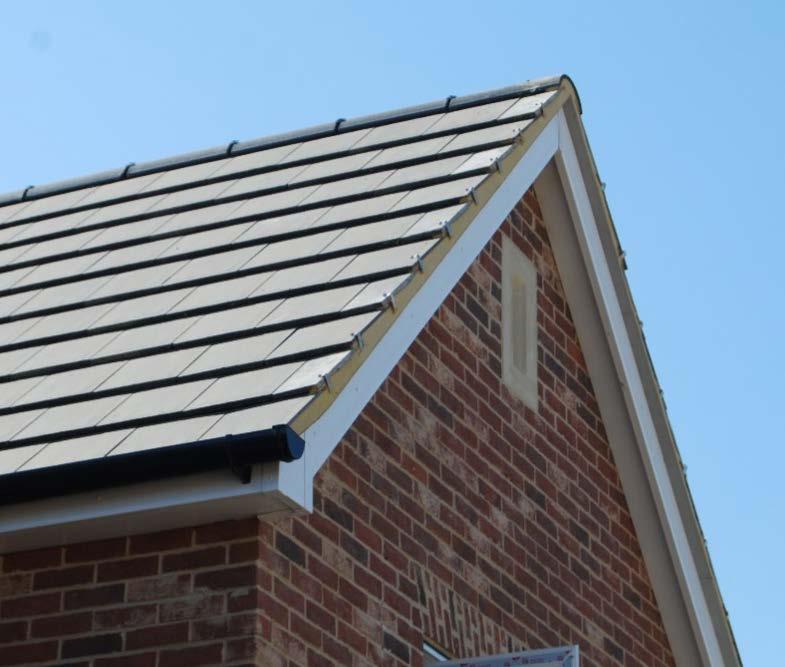
Verges
Verge clips MUST be in twice fixed to battens and be in full contact with the roof tile (if not the clip is not fulfilling its function to hold tiles down. In the case of profiled tiles, differingsized clips may be required to achieve this, depending on where the cut occurs.
Batten finished with a contrasting preservative where cut
A cut tile being inserted into a double-lapped roof.
take
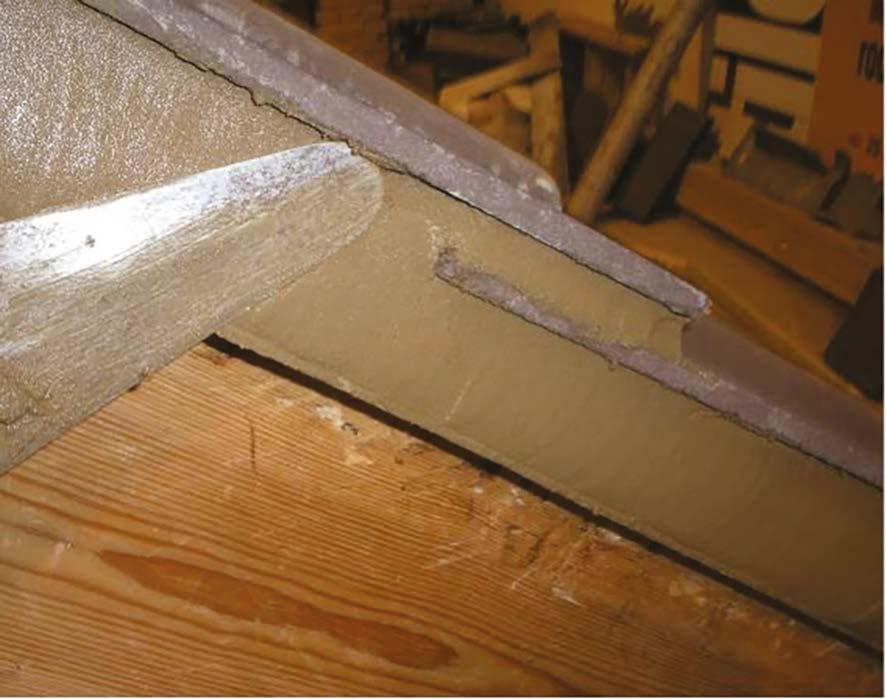
Rafter / truss to wall alignment is important to ensure tile batten holds down the undercloak.
Undercloak should be bedded on mortar. External wall should be 10mm lower to allow bedding.
Technical images source: nhbc-standards.co.uk
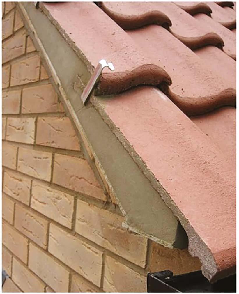
Where verges are wet bedded, the tiles must be bedded onto a firm 100mm mortar bed to provide full adhesion and compaction. It must never be pointed-in after tile laying.
Slates do not require mortar bedding.
Underlay
n over wall cavity
Verge tiles bedded in mortar on undercloak
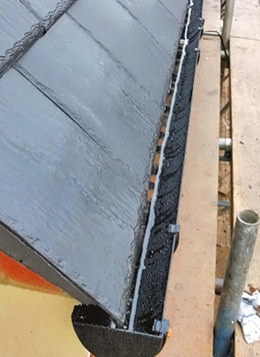
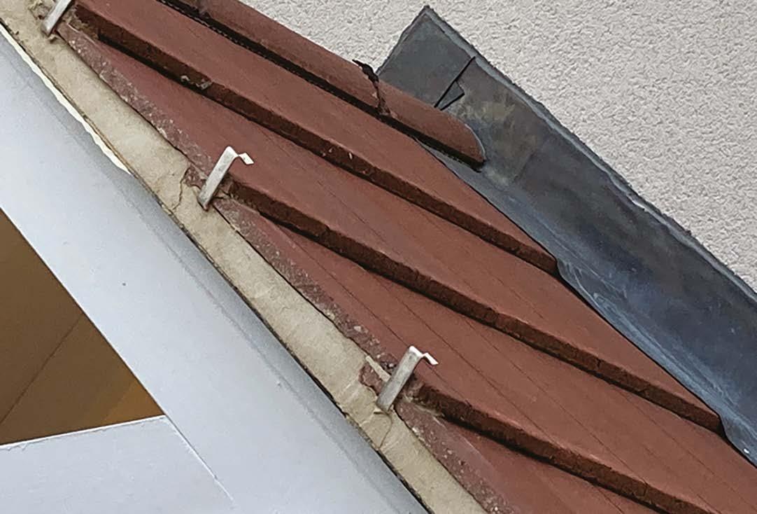
Neat, well-constructed wet verges with verge clips, all in contact with the tiles and the bedding mortar neatly pointed up.
Where wet-bedded verges are specified, these must be neatly shadow pointed as indicated below and not flush pointed.
These are the wrong verge clips - they should be in contact with the tile holding it down. This image also indicates that the roof wasn’t set out prior to tiling, as the cut tiles should be on the right-hand verge, not the weaker left hand verge.
10. Roofs
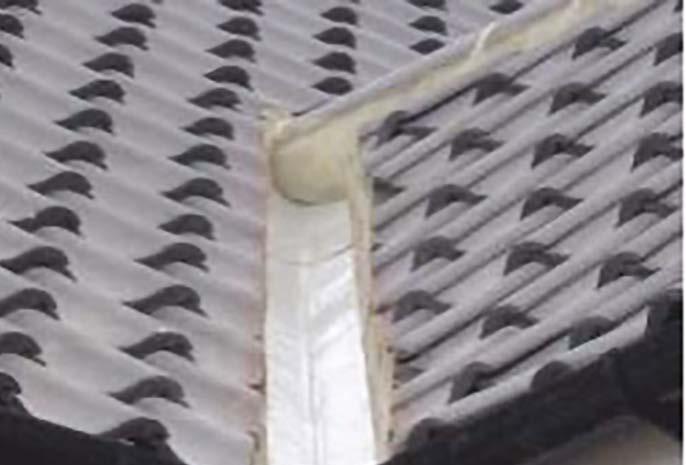
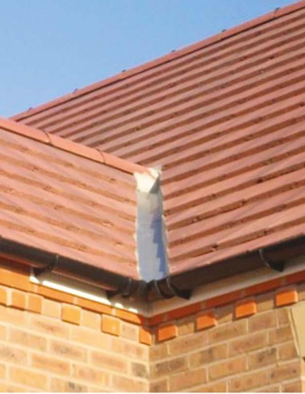
Valleys
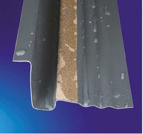
These days almost all valleys are constructed using a dry GRP valley former. Please refer to the valley manufacturer’s standard instructions for their installation. This should typically include a suitable timber valley former support under the tray. Fascia boards should be notched to avoid the valley tray distorting as it runs to the gutter line. Alternatively, a lead saddle can be provided at the eaves location.
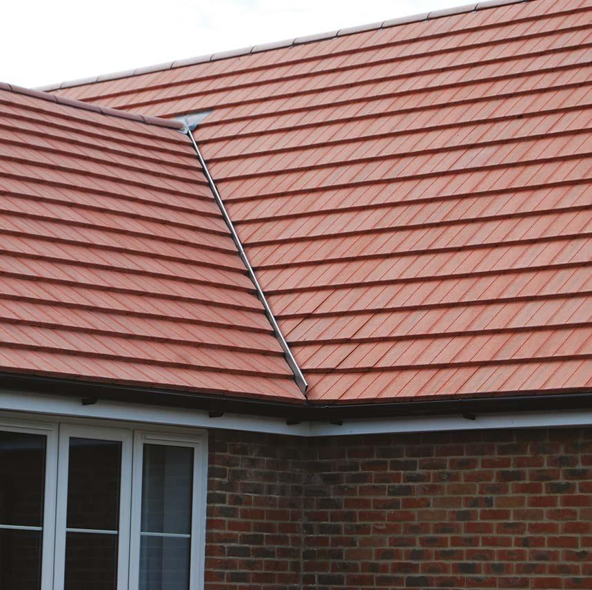
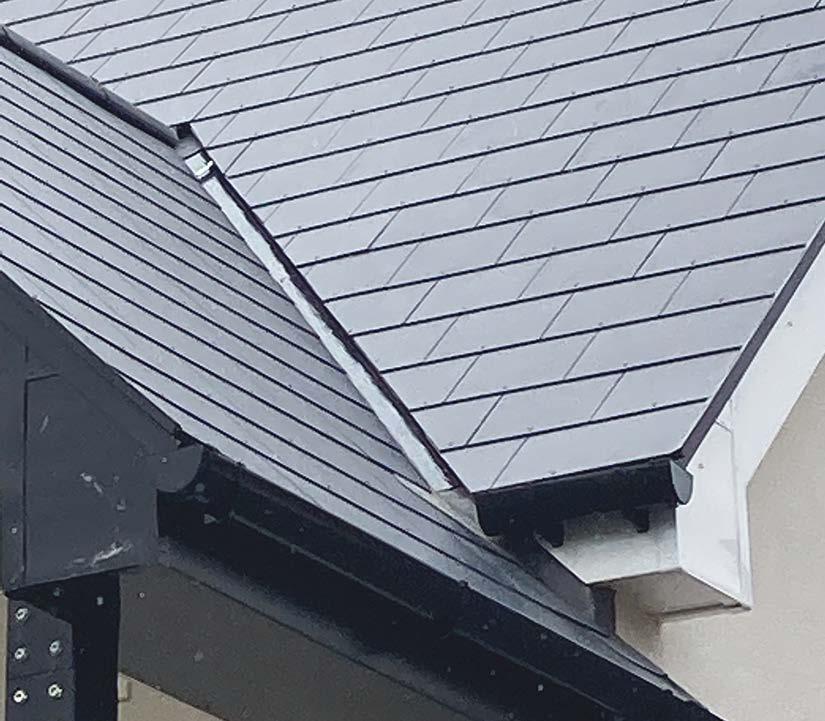
Running ridge tiles over valleys is bad practise as this creates a large mortar bed liable to crack, and often conceals the lack of adequate saddle flashing over the valley.
A more robust solution that should be followed maintains an open valley across the line of the ridge as detailed here.
GRP valley gutter
lead saddle flashing dressed over GRP valley gutter
Small cut tiles
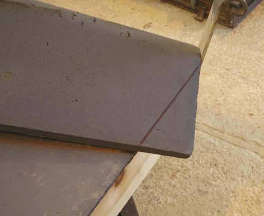
When cutting valley tiles, please avoid very small cuts. For doublelapped tiles or slates, use 1 1/2 tiles and for single-lapped interlocking tiles, bond tiles together using a manufacturer’s approved adhesive.
Valley tiles must NEVER be cut in situ. They must be marked and wet cut away from the roof to avoid potential damage to the valley liner and respiratory concerns caused by dust inhalation.
Incorrect use of small
Often, small cut tiles are unavoidable within roofs, especially where features such as roof lights, dormers or PV panels exist.
While double-lapped tiles or slates are generally available in 1 1/2 tile modules, overcoming the need for small cut tiles, single-lapped interlocking tiles are typically designed to fill large, uncomplicated roof areas and are generally not available in larger sizes.
All tiles should be twice mechanically fixed and where small cut tiles are unavoidable, these should be bonded to a larger tile using a suitable cartridge-applied adhesive, approved by the tile manufacturer.
turned up behind
Tile and a half used to avoid small cuts or to extend tiles further into the valley
In this situation, where single-lapped tiles are used, the only solution is to carefully bond the cut tile to the adjacent tile using a manufacturer’s approved adhesive.
Where pitched roofs abut walls, a cavity tray must be installed with a joint raked out whilst green to receive a code 4 flashing dressed under the tray. A minimum of one brick (75mm) upstand is required from the finished roof and a minimum 150mm downstand.
Soakers beneath each tile and overlapped by the flashing
Double lapped valley tiles
Cut tile to a weak point
Cut tile
cuts
Valley tile now wider at the tail (stronger)
Clip free edge of flashing; method depends on exposure
Lead flashing
Cavity tray wedged into joint below wall DPC
Underlay
flashing
Underlay up
Stepped held with
10. Roofs
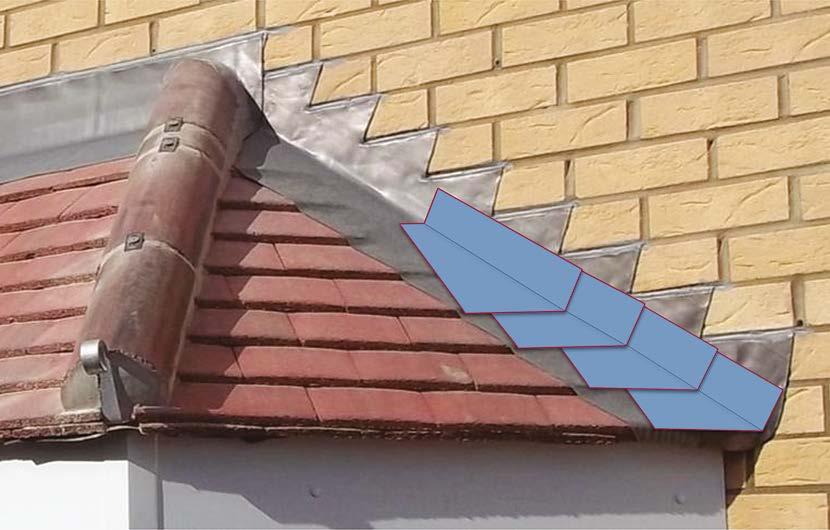
Where double-lapped tiles or slates abut a wall, this can be formed using code 3 lead soakers with cover flashings or proprietary roof abutment gutters.
Cover flashings only acceptable on plain tiles where soakers (or Secret gutters) used.
Underlay turned up behind flashing
Underlay turned up behind flashing
Soakers beneath each tile and overlapped by the flashing
Stepped lead flashing held in mortar joints with lead wedges
Lead flashing wedged into joint below wall DPC
Clip free edge of flashing; method depends on exposure
A nicely detailed hipped bay roof using double-lapped clay tiles and baby hip tiles. These are fully wet bedded with hip iron supports (hips to bay windows do not require mechanical fixing), however this should be actioned by carefully drilling through the crown of the tile and fixing with a stainless-steel screw and rubber washer. The roofer has also taken care to introduce a cut hip tile within the body of the run of tiles and not at the more exposed and visually obvious end tiles.
Code 3 lead soakers and a code 4 lead cover flashing neatly finished the abutment to the wall – all tucked under the horizontal tray and proprietary stepped cavity tray.
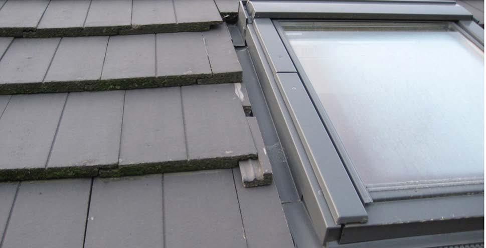
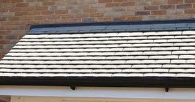
Where single-lapped concrete interlocking tiles are used, soakers are not applicable. Abutment solutions depend on whether the tiles are profiled or flat.
Profiled tiles can simply be dressed with a suitable flashing that must terminate into the trough of the tile, or a proprietary abutment gutter can be used.
Where the tiles are flat, or a profiled tile is cut, removing the trough, a proprietary abutment gutter MUST be used. NHBC no longer accept proprietary plastic slide-on soakers.
Only acceptable into a rolled / profiled tile
An example of a proprietary roof abutment gutter
Underlay turned up at abutment
Min. 150mm
Soakers beneath each tile and overlapped by the flashing
Fire barriers
A stone-wool fire barrier being installed over a fire wall compartment line between each tile batten (Note: the Hill policy is now to use wired tile batten barrier, such as that provided by ARC)
Here you can see the compressible stone-wool fire barrier to the top of a spandrel panel, maintaining the fore compartment through the roof covering. (Note: the Hill policy is now to use the ARC spandrel barrier).
An excellent example of very well-cut mitres to the hip and ridge intersection preventing the commonly seen ‘big top’ effect, where the ridge tiles rise due to incorrect mitres being formed. Also, very neat mechanical fixing including the introduction of an additional fixing to the ridge and hip ends to ensure they are twice fixed, to prevent wind uplift.
10. Roofs
Photo-voltaic panel installations
There are two basic forms of solar panel installation to pitched roofs.
1. On roof
A framing system is fixed through the roof covering and the panels are mounted on top of the roof covering. Fixing details must not compromise the weather resistance of the roof covering or lift tiles from their natural lay.
2. In roof
The PV is an integral part of the roof and its installation must be flashed and sealed to maintain the roof’s weather resistance. Due to the impervious nature of ‘in roof’ PV panels, additional roof vventilation may be required where this solution is adopted.
In all cases:
y Waterproofing details that rely solely on sealant are not acceptable.
y Bolt through fixings are NOT suitable for double-lapped tile or slate situations. They must pass under the tiles.
y Bolt through fixings to single lapped tiles must not penetrate interlocks or be located less than the minimum side lap dimension for the tile/pitch.
y Tiles must lay flat and not be stressed by any PV fixings.
Flat roofs
Flat roofing systems are typically bespoke and should therefore be designed as a complete system in accordance with NHBC Standards Chapter 7.1 or section 11 and 12 of the LABC Technical Manual.
Consideration should be given to the specified surface and functional specification of the roof system (i.e. green, brown, blue systems, podium, terrace, vehicular access etc.) and ensure that the roofing system is designed accordingly, taking into account:
y Dead and live loads (e.g. trees, vehicles etc.)
y Weight of the roofing system
y Wind uplift
y Functional performance
y Surface finish
y Buildability / compatibility with programme and sequencing requirements
y Robustness against physical damage during construction or in use
y Simplicity and skill level required to install
y Sensitivity to failure (e.g. single ply membranes vs bonded systems)
y Impact of inclement weather during construction / cleanliness requirements
y The type of substrate and system compatibility
y Falls / drainage requirements
y Fire – Refer to Hill Technical Policies, job specific fire strategy documents and current legislation depending on the location of the roof and type of building
y Potential hot work fire and CDM risks
y Movement
y Complexity of junctions and interfaces
y Thermal performance requirements
10. Roofs
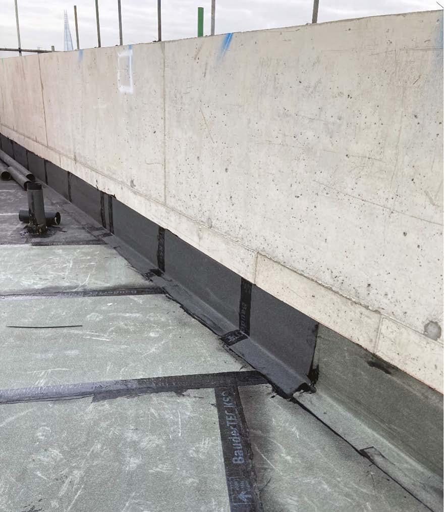
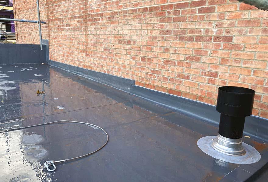
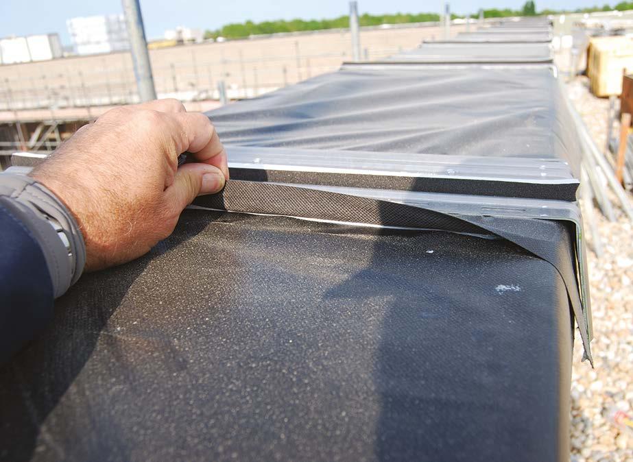
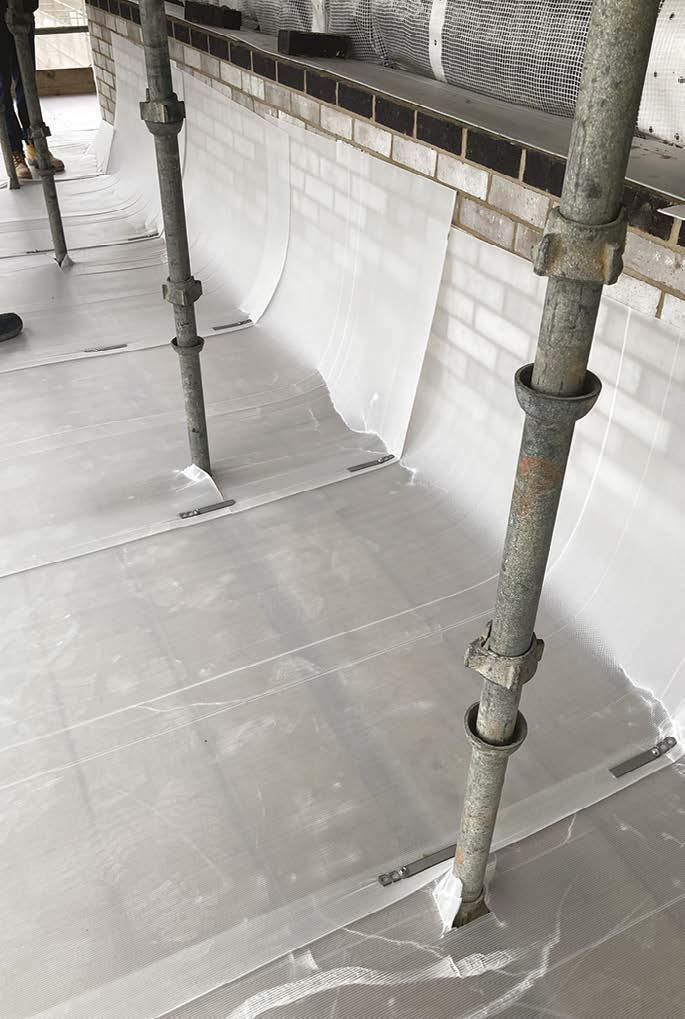
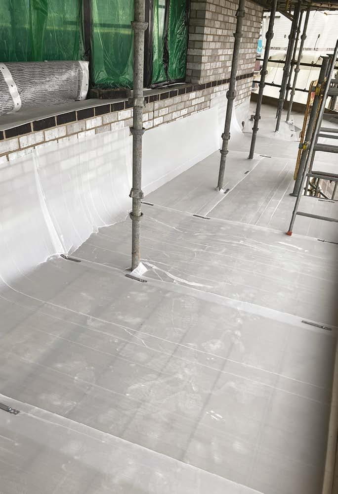
In this photo, the BRoof (t4) roof membrane is bonded to the parapet wall of this building up to a height of 150mm above the roof finish level. Membranes above this roof interface must be a minimum fire classification of B-s3,d0 to meet Hill’s and Approved Document B guidance.
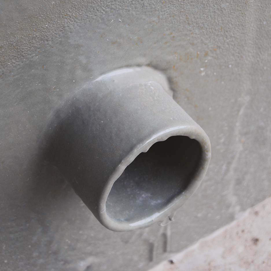
Flat roofs need to have facilities to manage rainwater in the eventuality of blocked outlets or drainage. Typically, these require overflow arrangements or multiple outlets with independent drainage systems.
In this image a cold spray applied system has provided a waterproof seal to the overflow pipe.
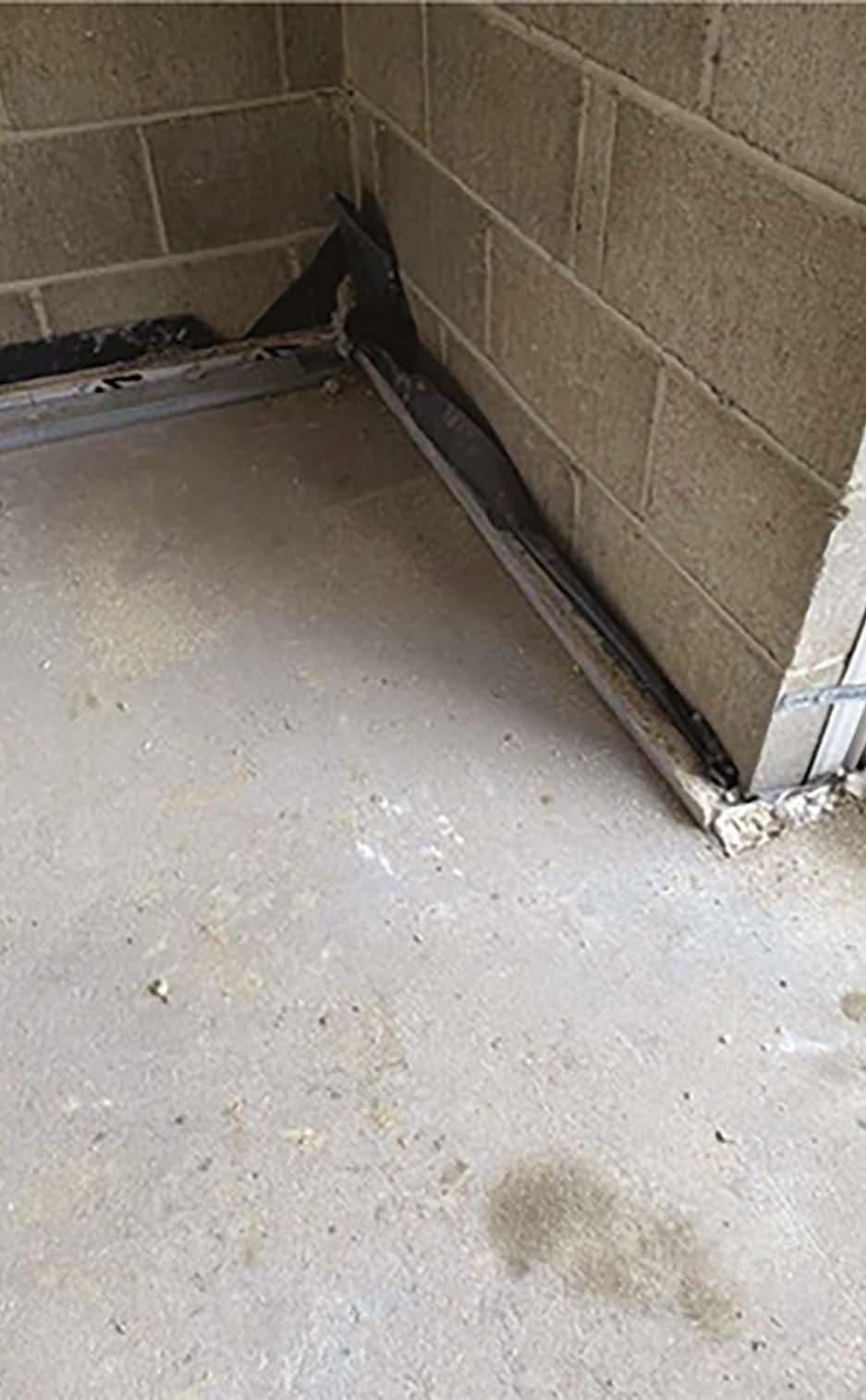
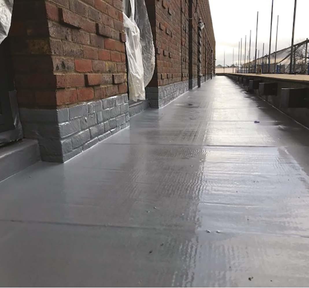
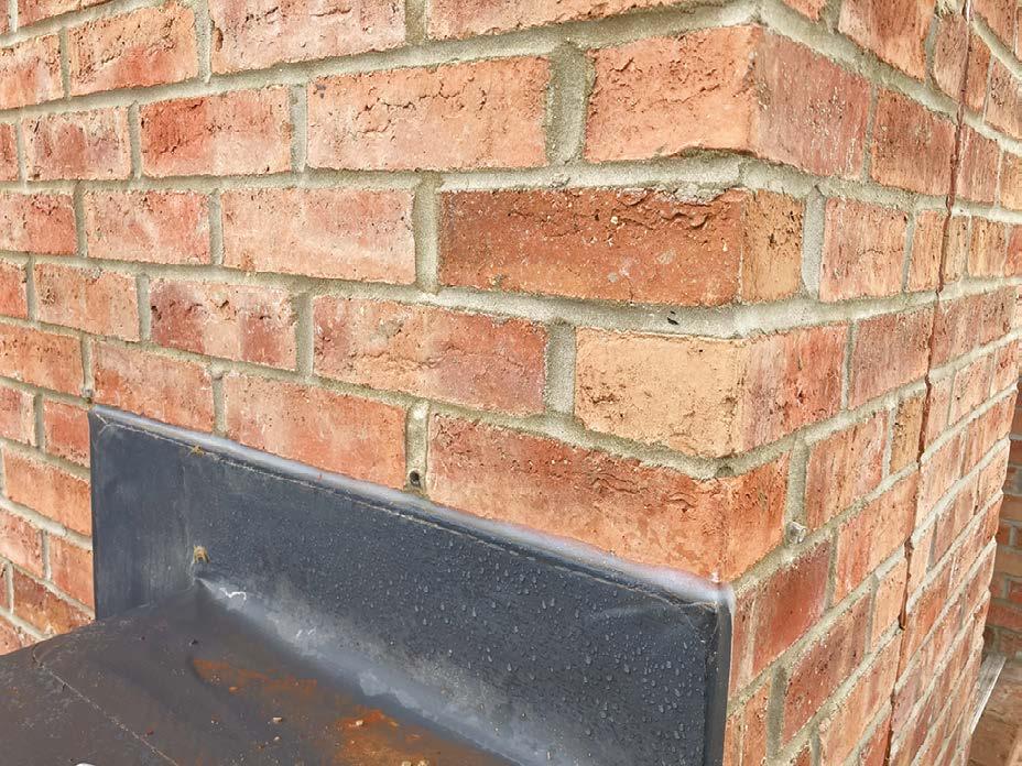
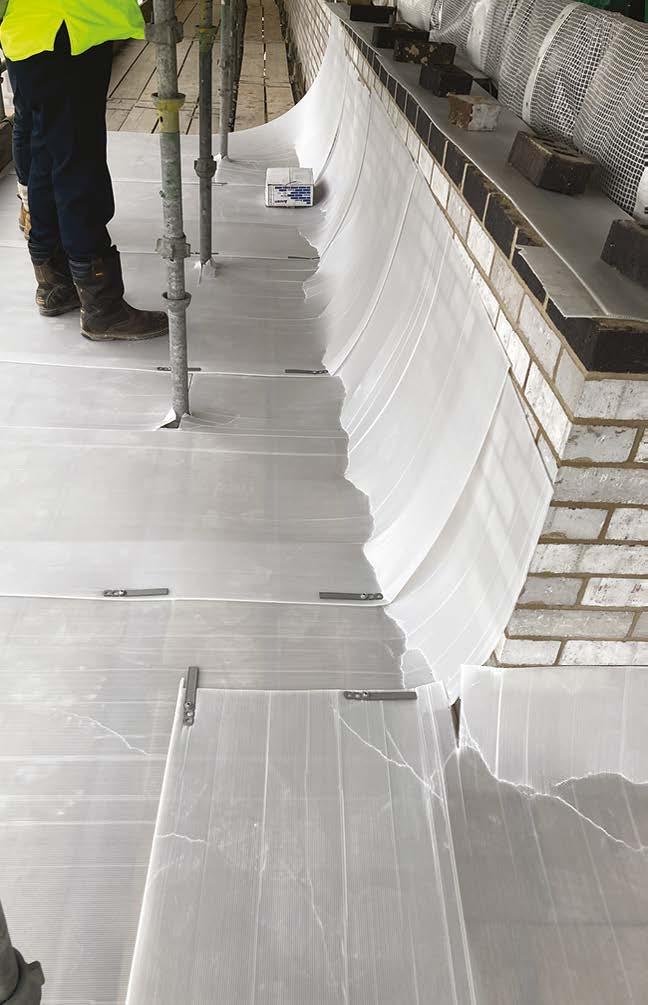
Flat roofs, terraces and balconies should include a 150mm upstand to perimeters to provide splash protection to the abutting wall.
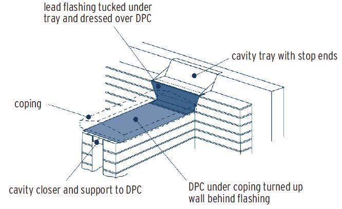
A suitable cavity tray should be installed to coincide with the top of the waterproof upstand. The tray should discharge over the waterproof upstand.
Parapet abutment to cavity wall
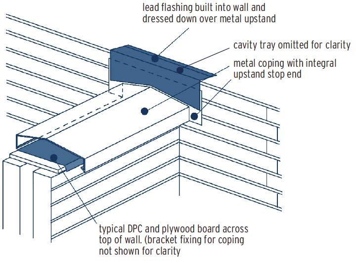
Alternative abutment using metal coping with integral stop end
Here, the flat roofing system has been incorporated within the parapet capping detail and links to the cavity tray.
All parapet walls require a well-installed DPC designed to resist the downward movement of water i.e. they must be continuous of fully lapped and sealed where jointed, as shown in this image.
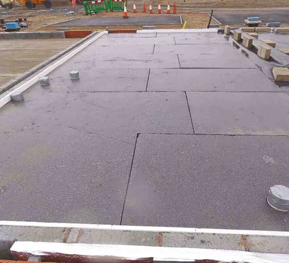
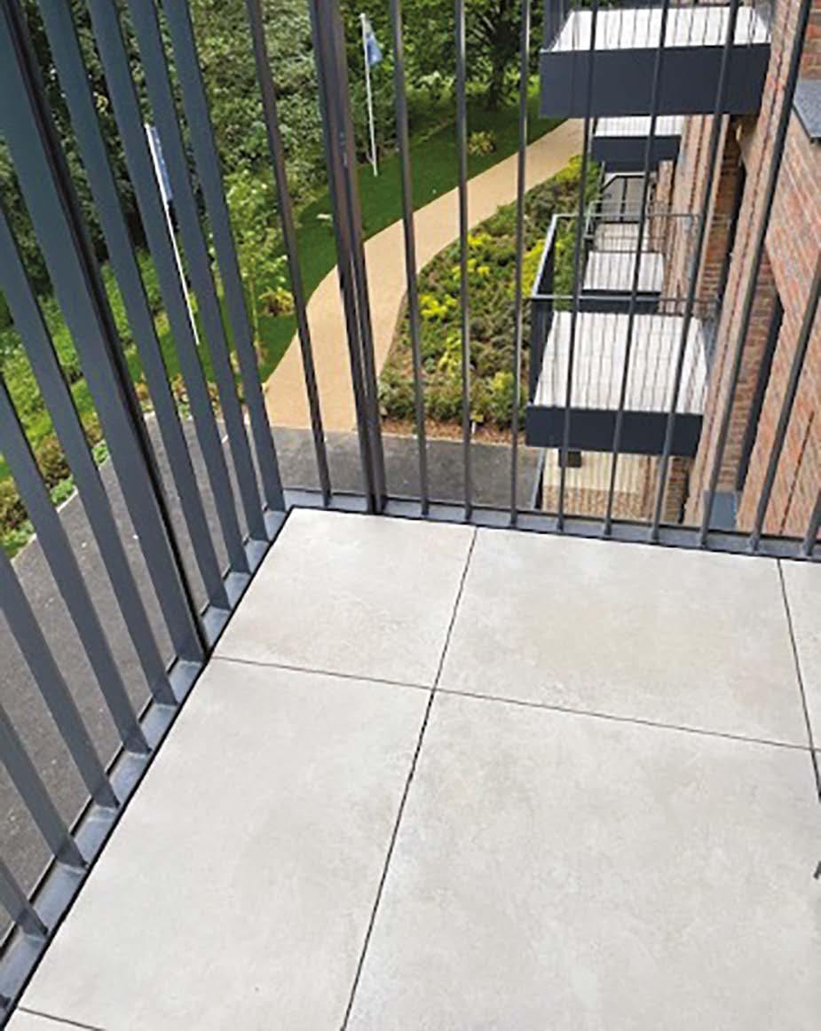
Very neat cutting and laying of paving has resulted in a first-class finish to this balcony, including a consistent margin to the perimeter edges.
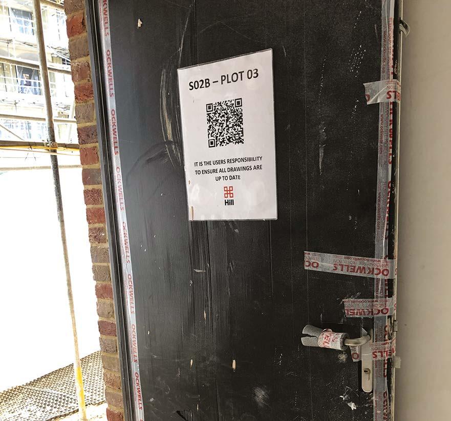
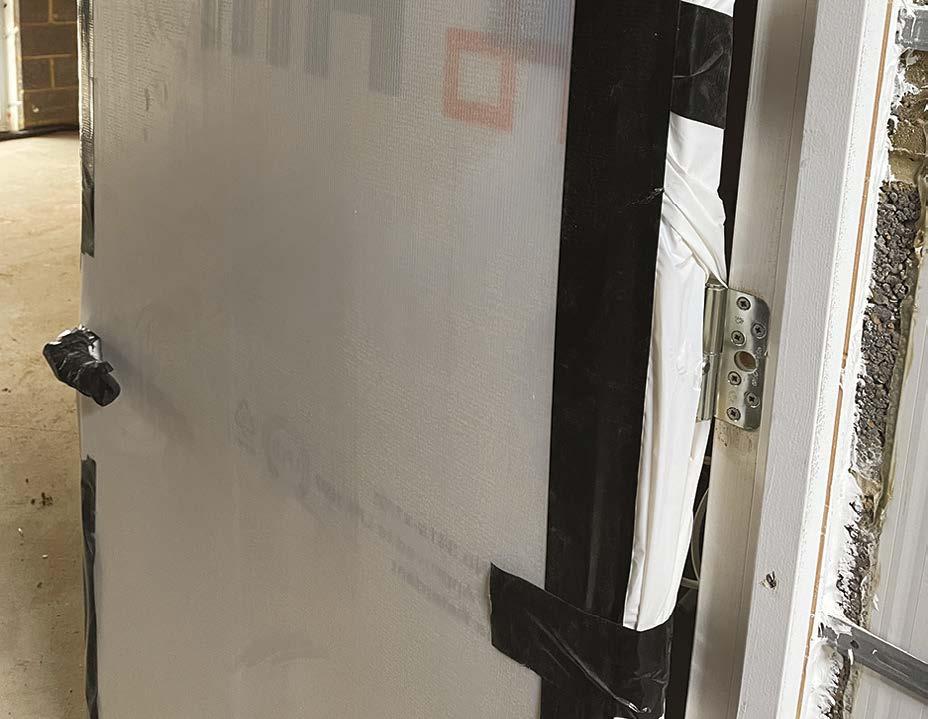
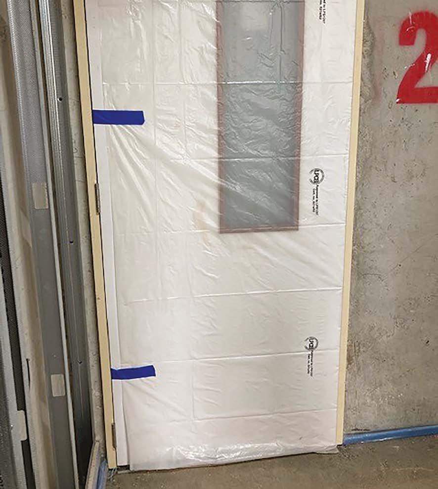
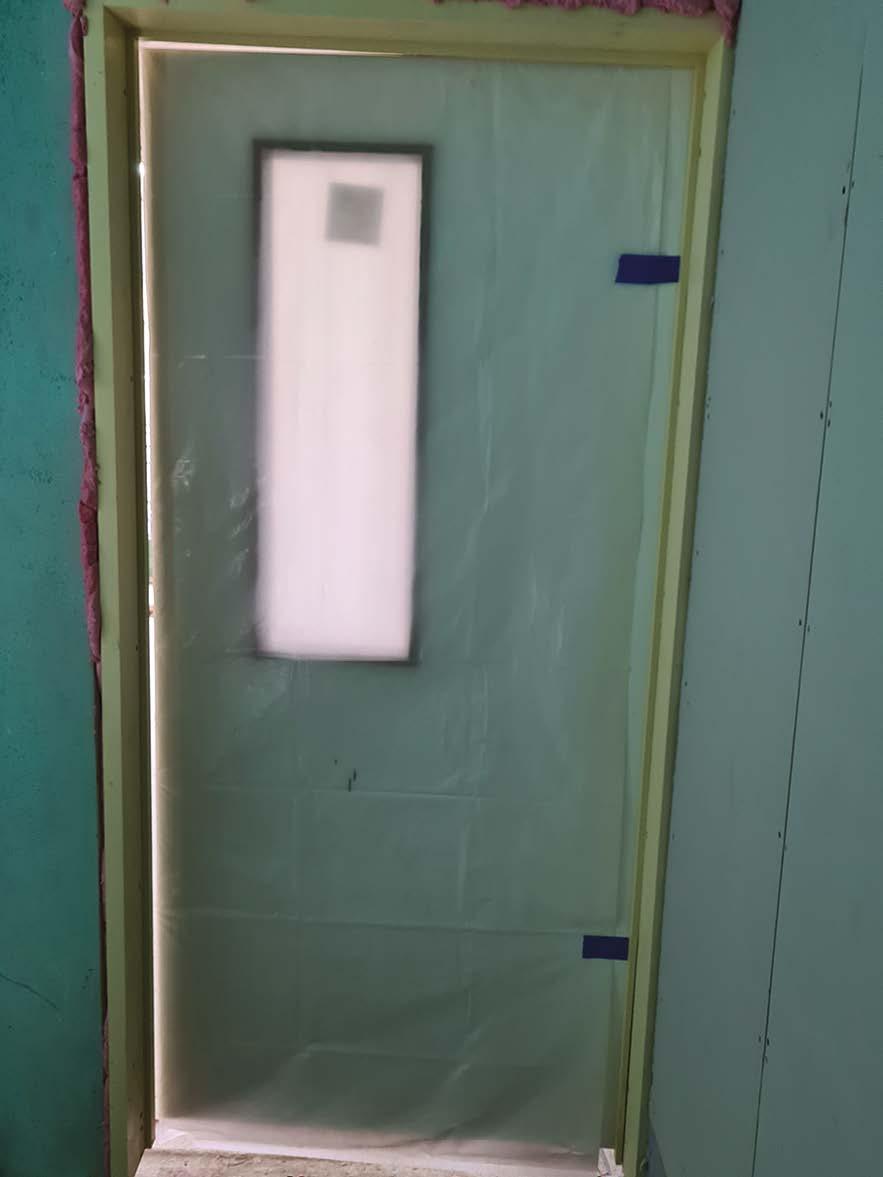
11. First fix (carpentry, M&E services, drylining, fire stopping and windows)
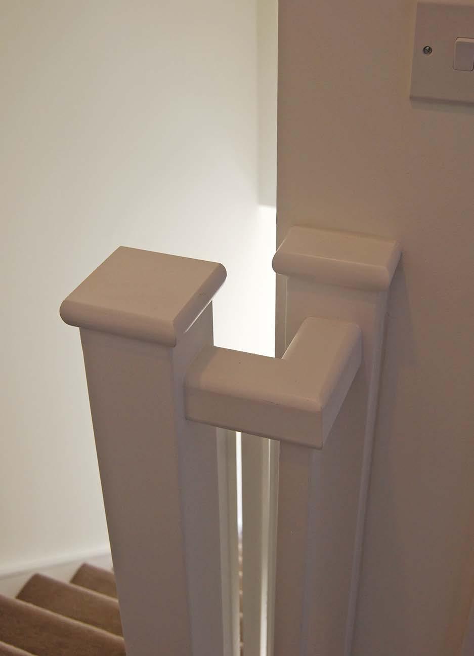
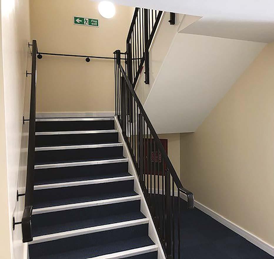
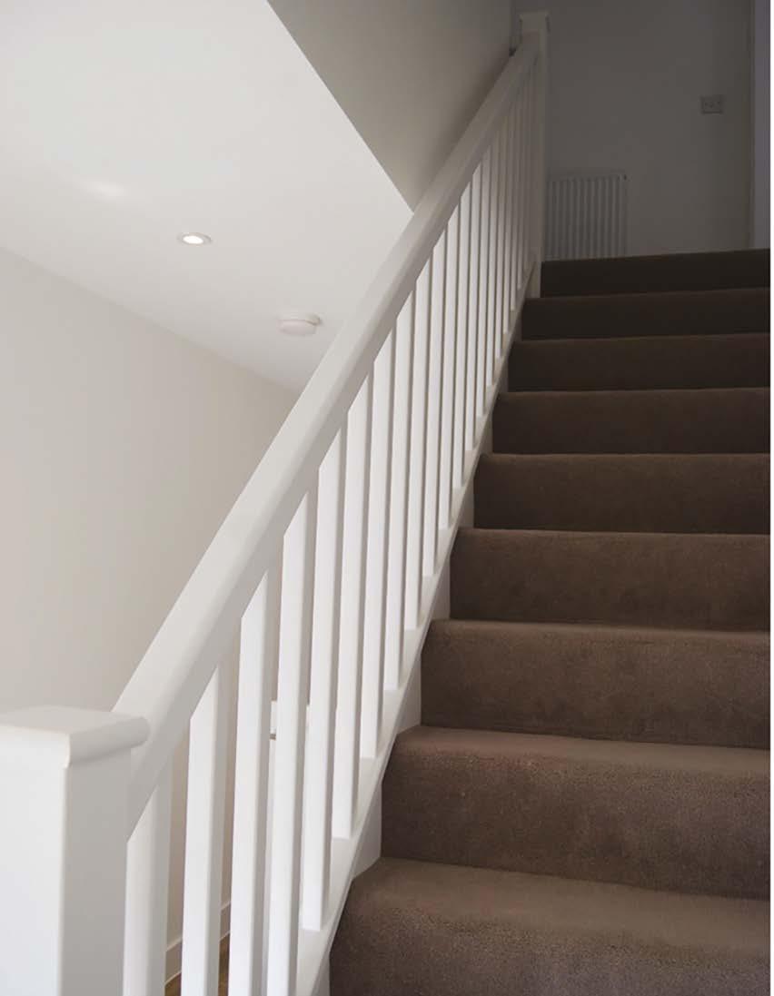
Carpentry Stairs
Key design and construction considerations:
y Stairs should meet the requirements of the building regulations.
y Have a minimum headroom ‘H’ of 2m as noted in the diagram below.
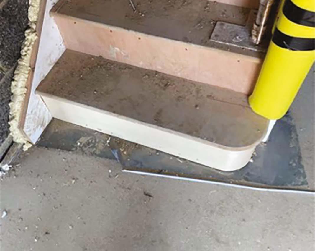
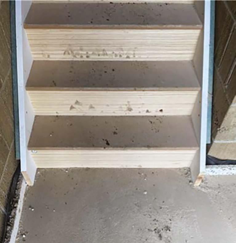
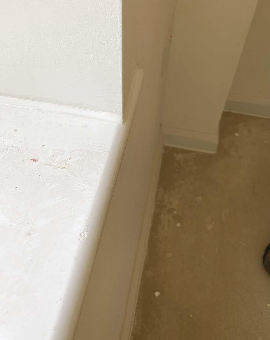
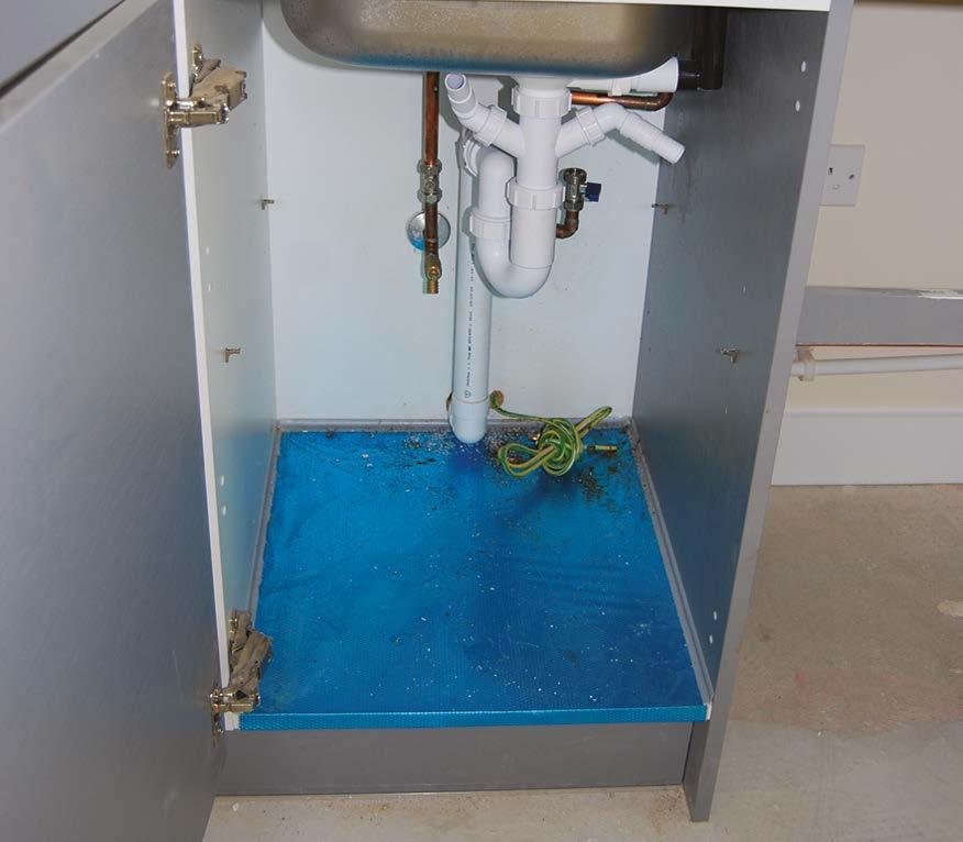
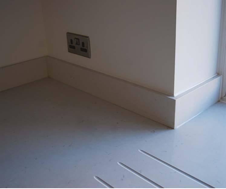
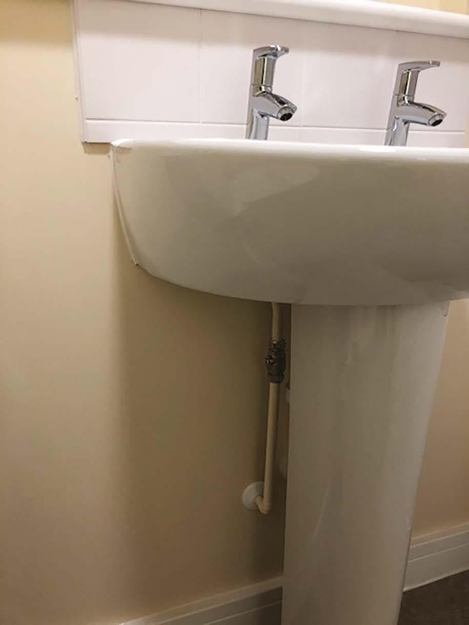
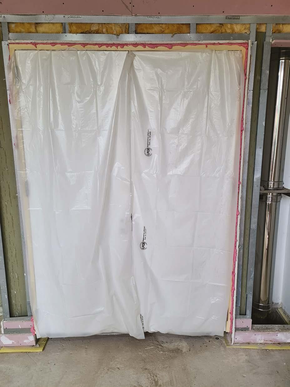
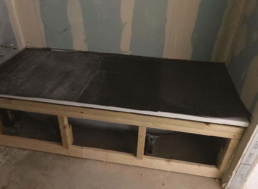
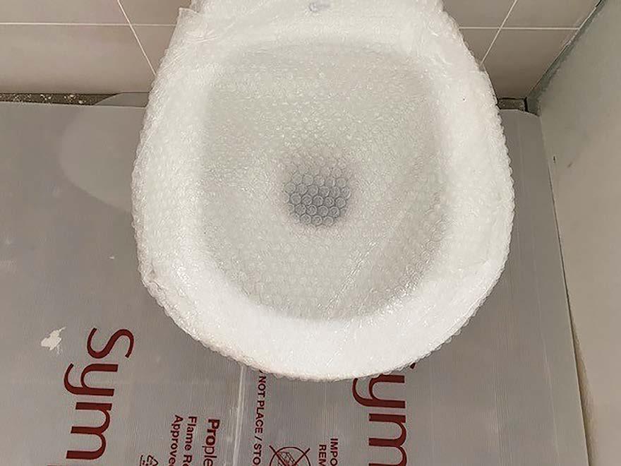
Where timber stairs sit on a wet screeded floor, a suitable DPM must be provided to protect the staircase from residual moisture contained within the screed until fully dried.
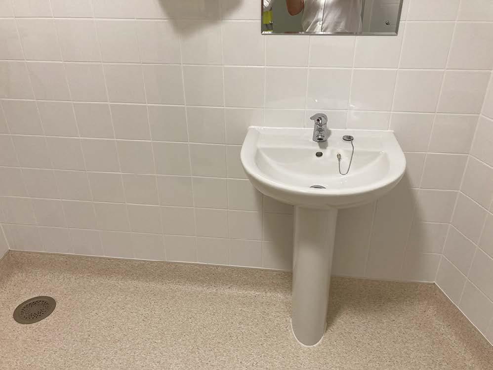
Diagram 1 - wash basin
This installation is not acceptable as the DPM was omitted.
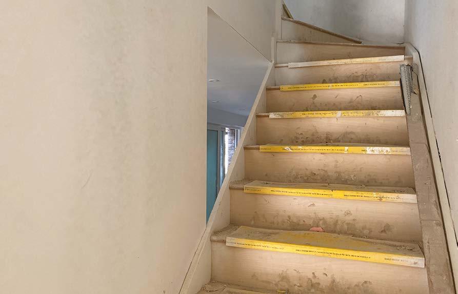
Squeaking and creaking stairs are a common defect within the industry, and we must do all we can to prevent this occurring in a Hill home. Care must be taken when fixing timber stairs as follows:
1. Keep stairs indoors and protected against excessive moisture (do not lay directly on screeded floors).
2. Ensure that all treads and risers are solidly glued and wedged into the stair strings.
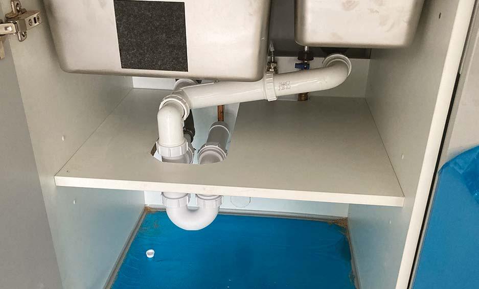
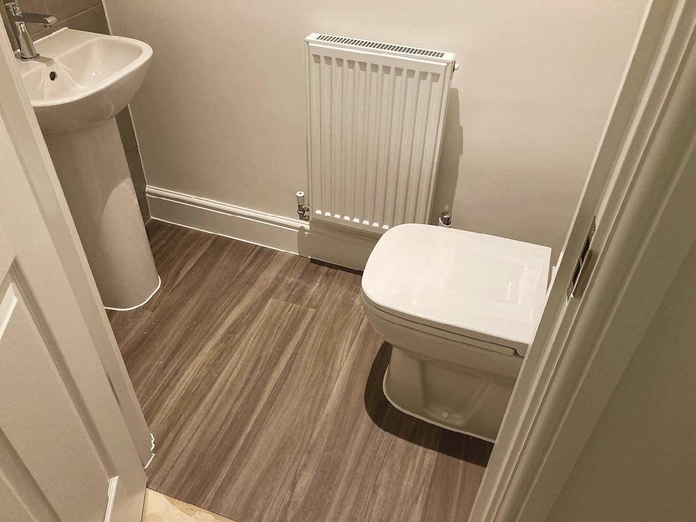
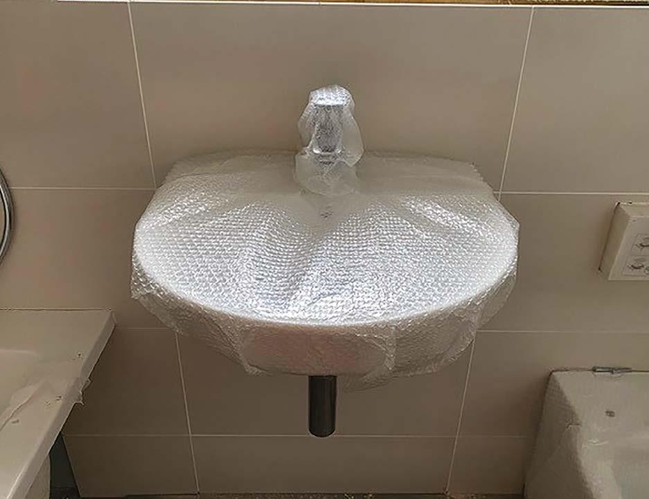
Diagram 2 - sink
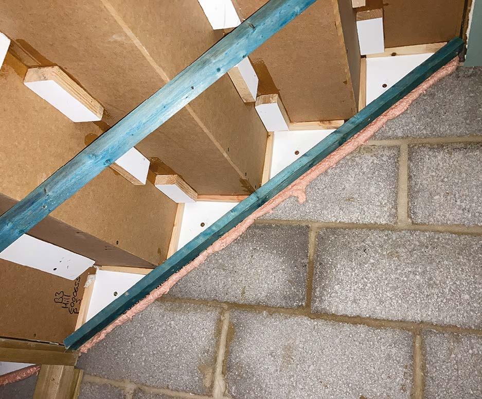
3. Ensure that stair strings are secured to adjacent walls with screws at 300mm centres, with solid blocking behind.
4. Treads and risers should be solidly glued and jointed to the strings.
5. Once installed, there should be no detectable movement within the stairs when in use. If there is movement, please address the adequacy of the fixings or consult with the stair manufacturer, as over time this will lead to creaks and squeaks along with cracking of finishes.
Fire – in many situations, the stair enclosure acts as a protected escape route. Where the underside of the stair structure is exposed to a fire risk (e.g. storage cupboard) or a space outside the protected enclosure, a suitable structure will be required to provide the necessary fire resistance. Typically, this will involve lining the underside / exposed stair structure with a fire protective plasterboard or fireline board.
images source: nhbc-standards.co.uk
In this photograph, the stair string is securely fixed to the adjacent wall at a maximum of 300mm centres through solid packing. To provide additional strength and to ensure a robust fire seal, fire foam has been sprayed between the stair string and the wall.
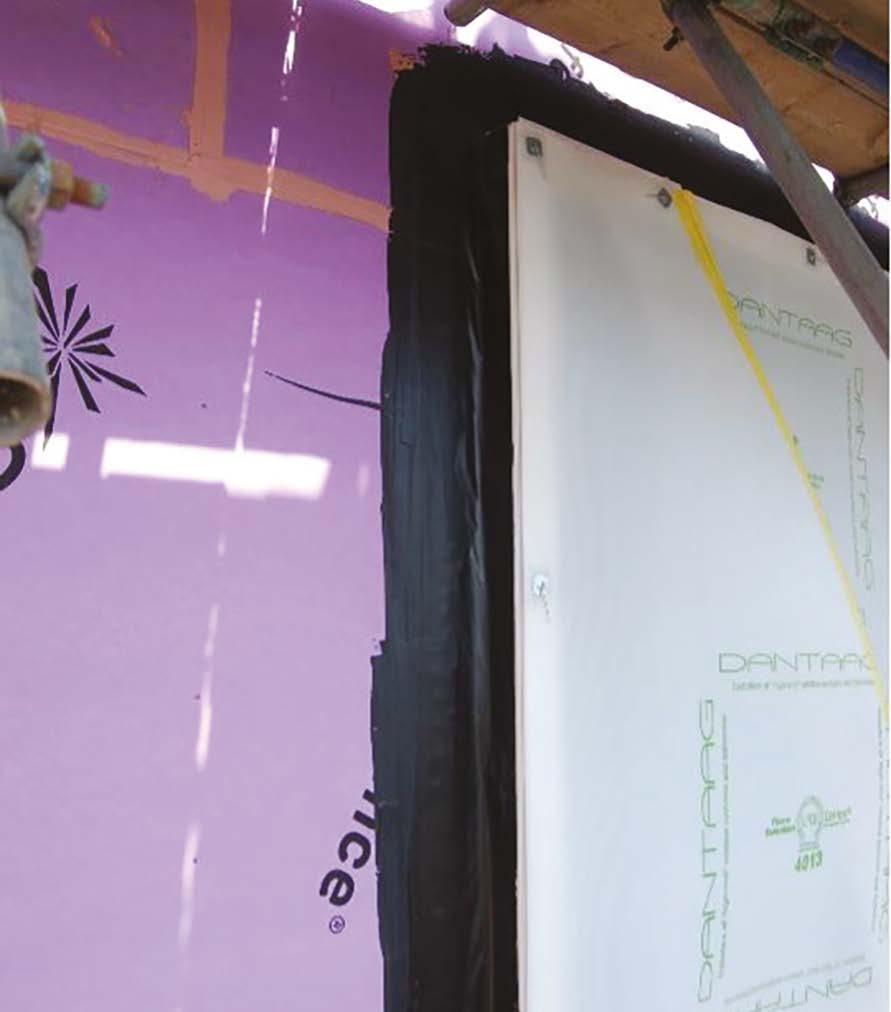
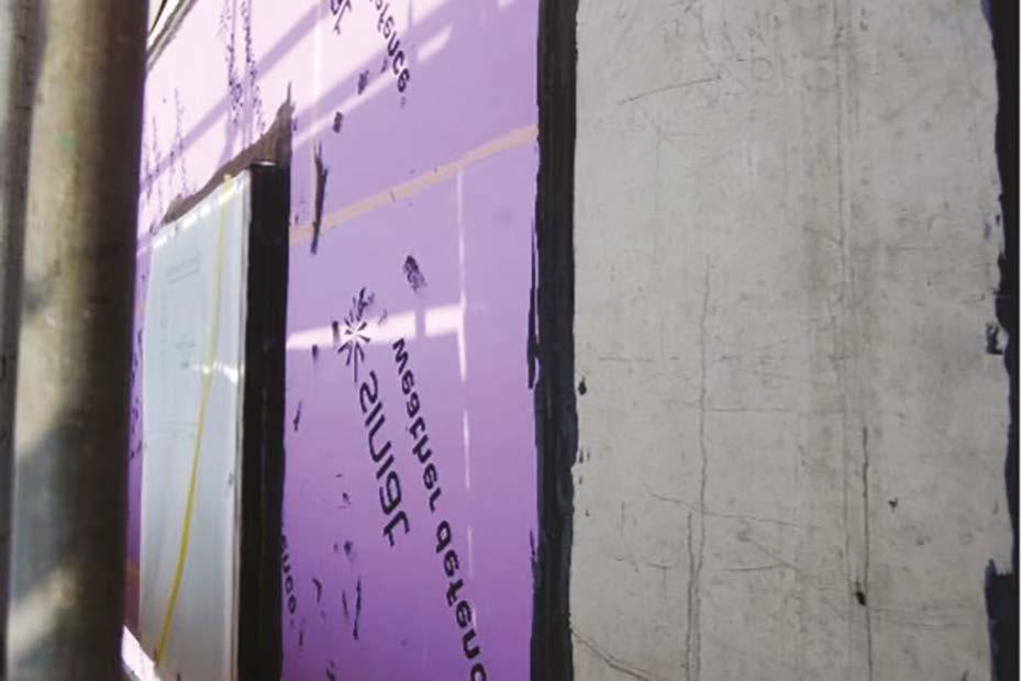
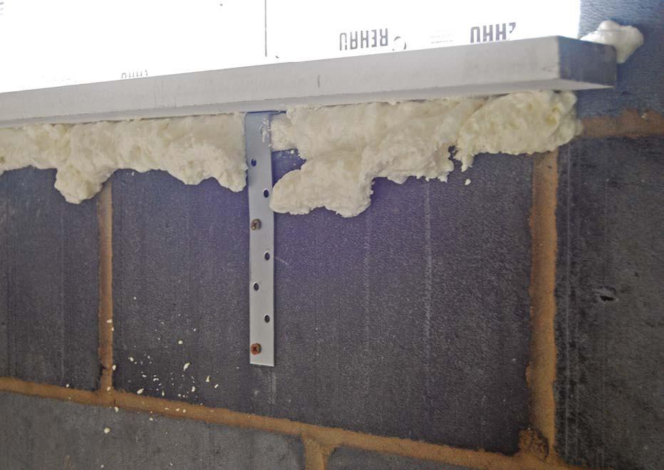
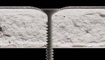
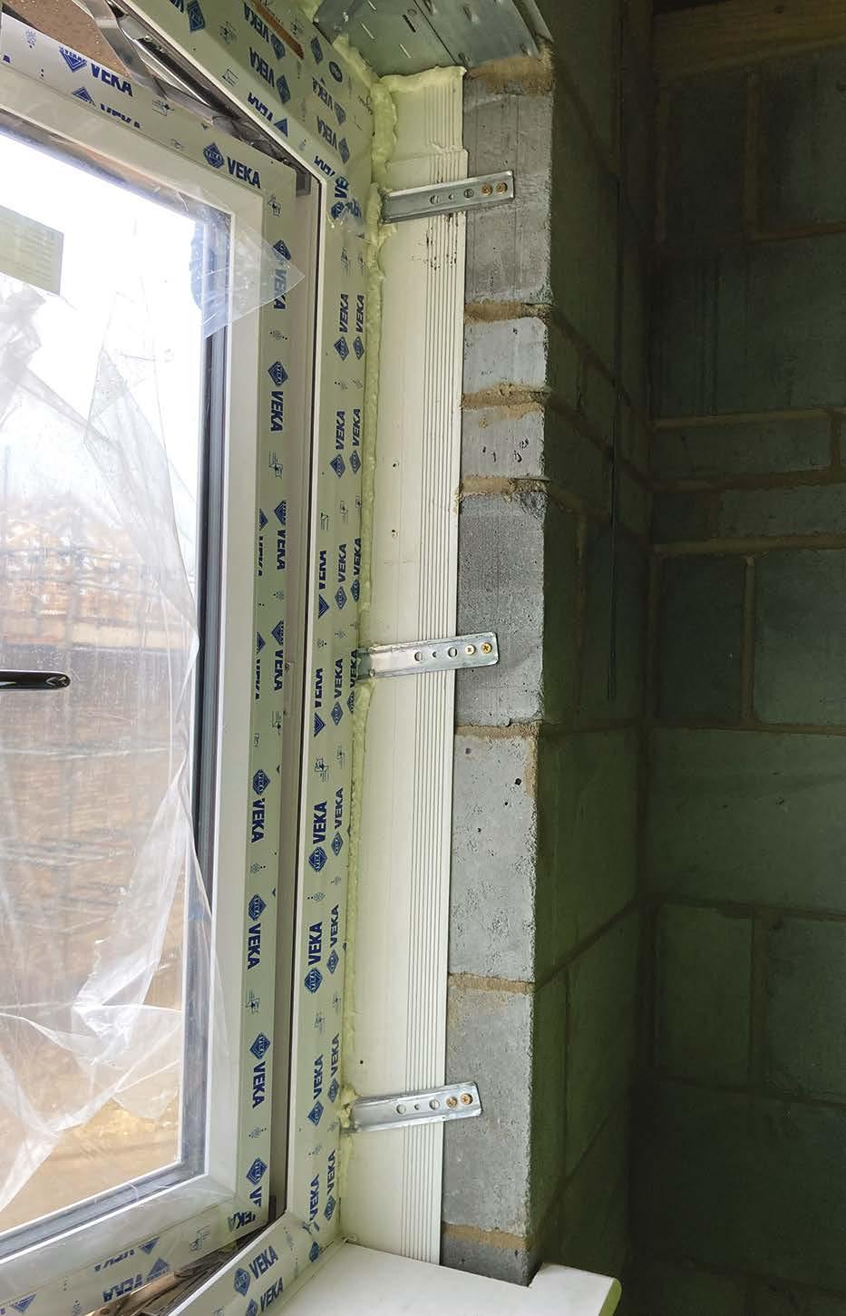
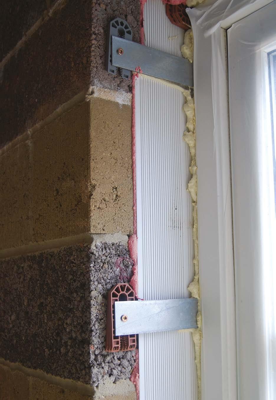
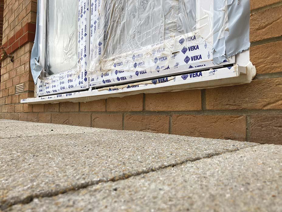
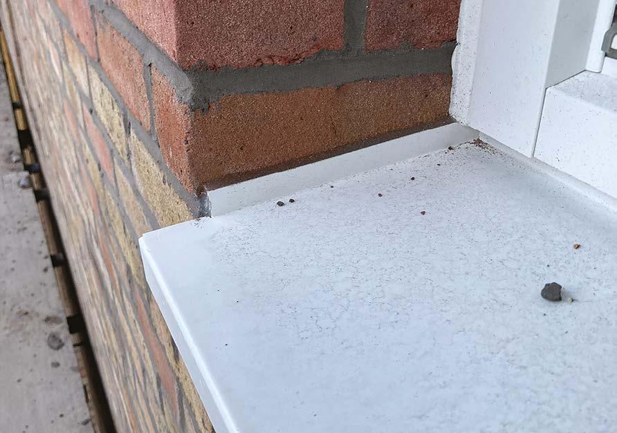
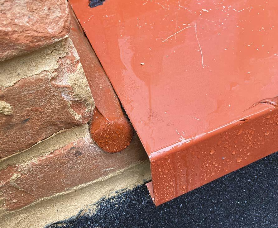
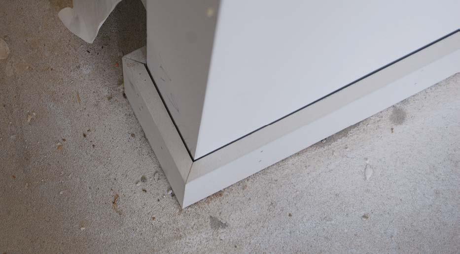
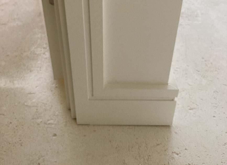
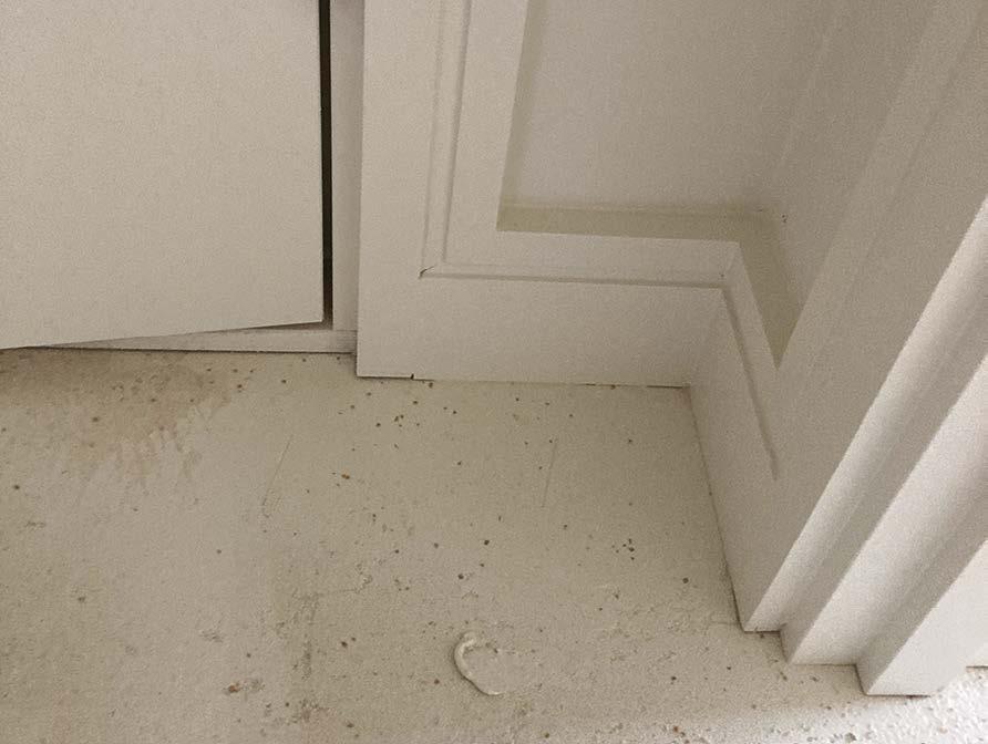
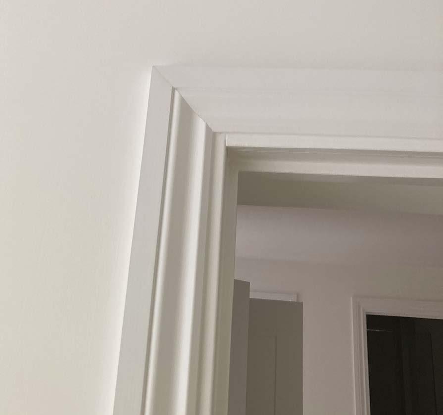
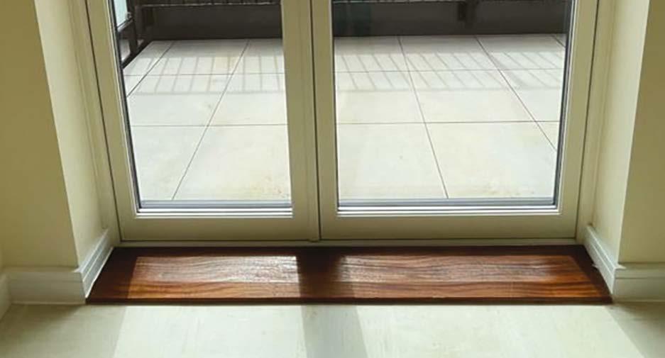
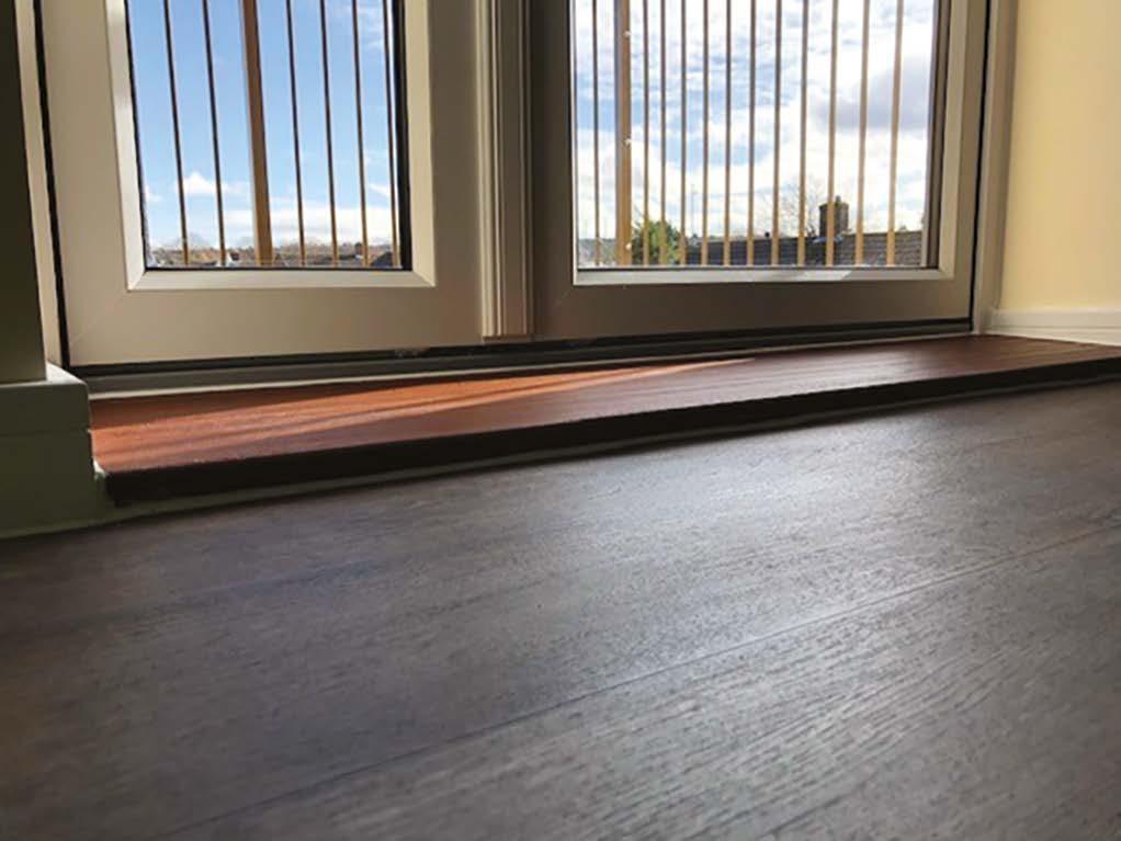
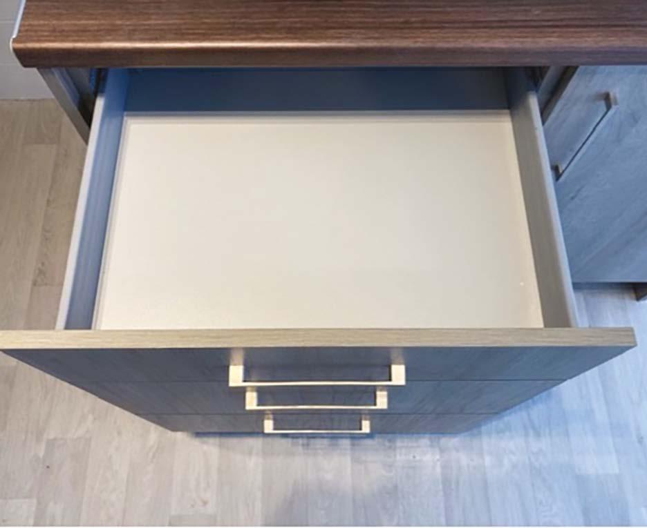
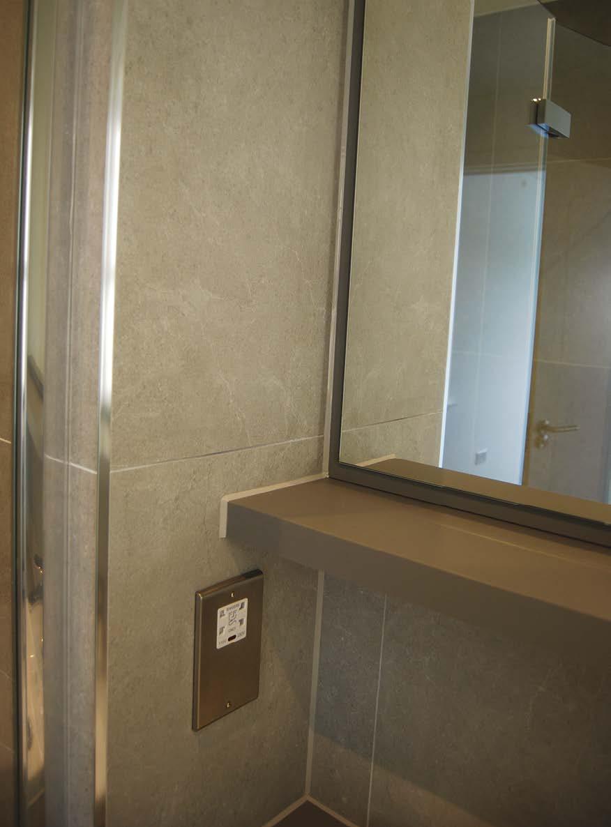
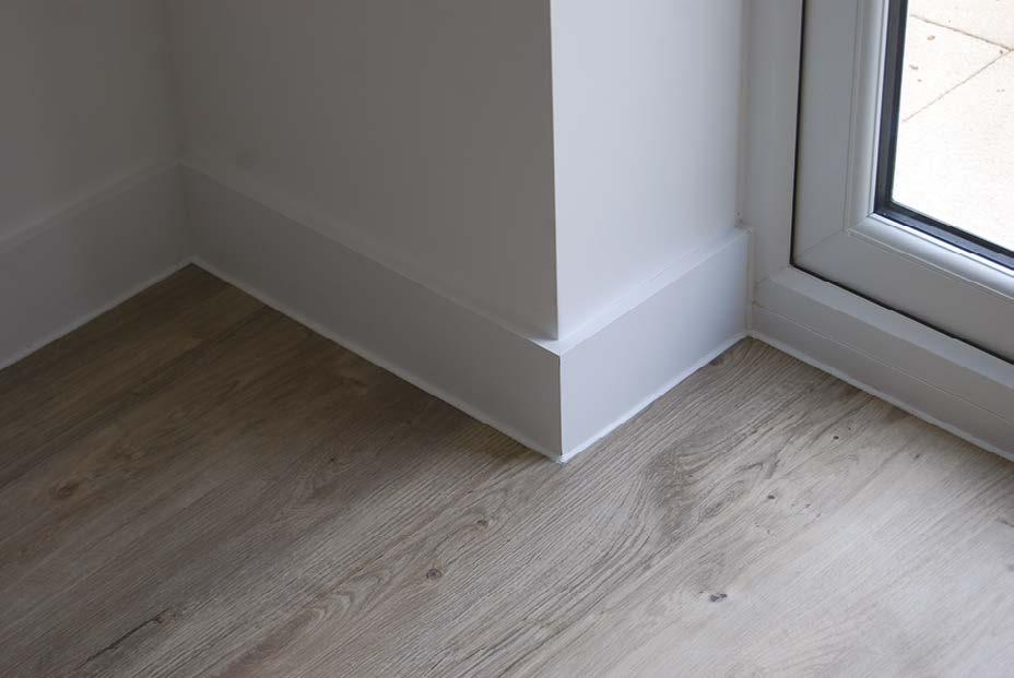
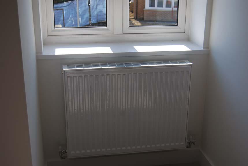
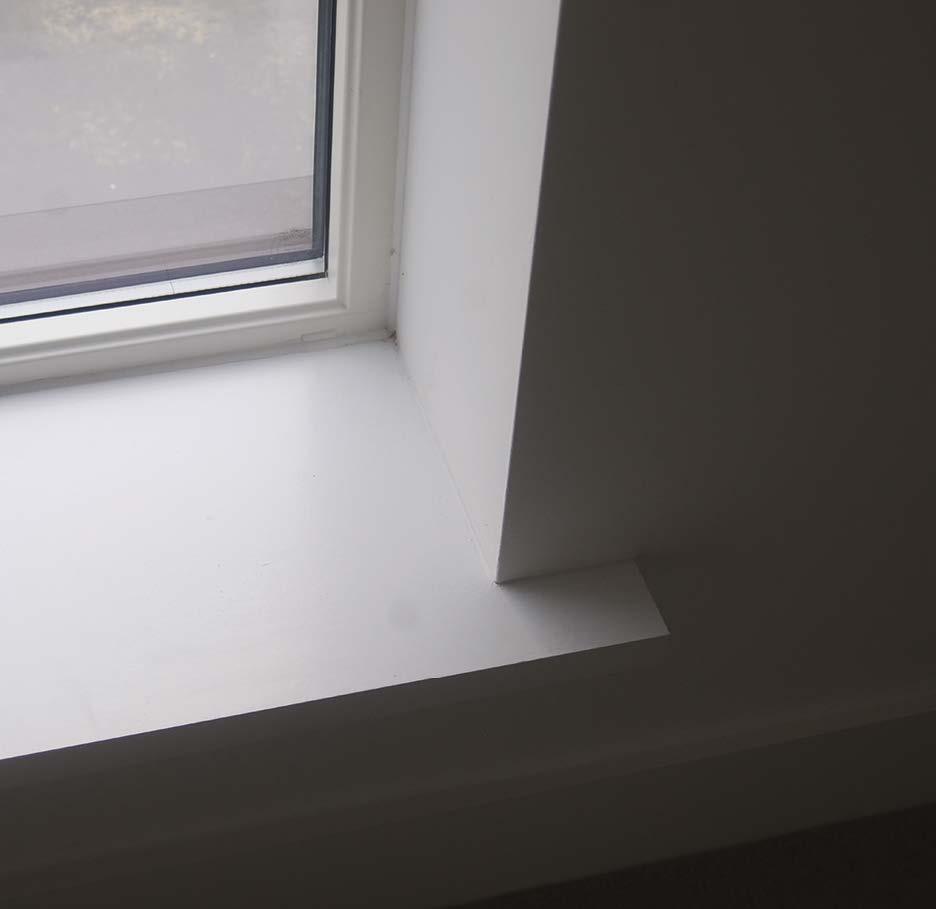
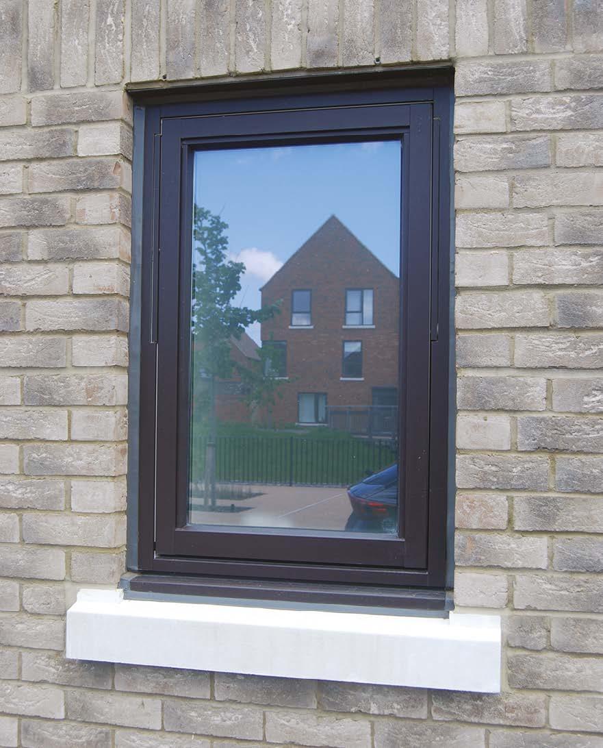
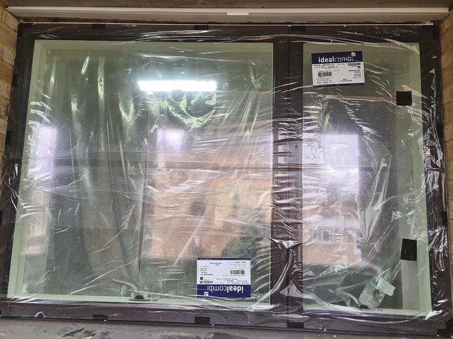
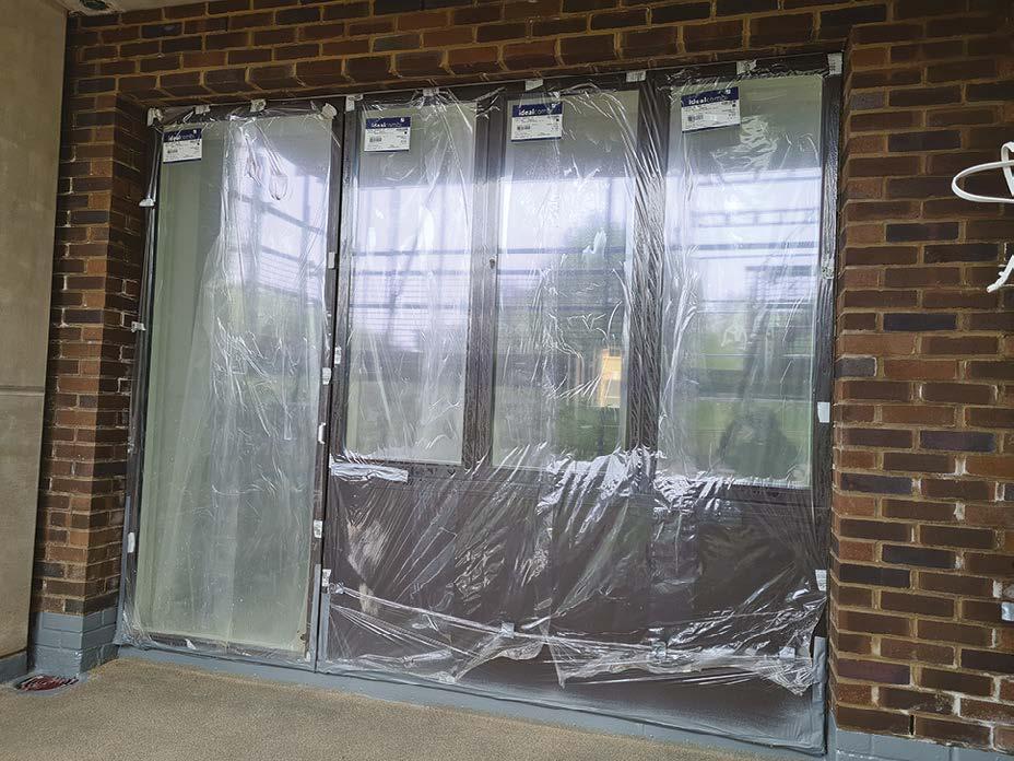
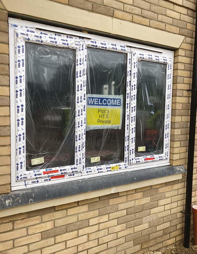
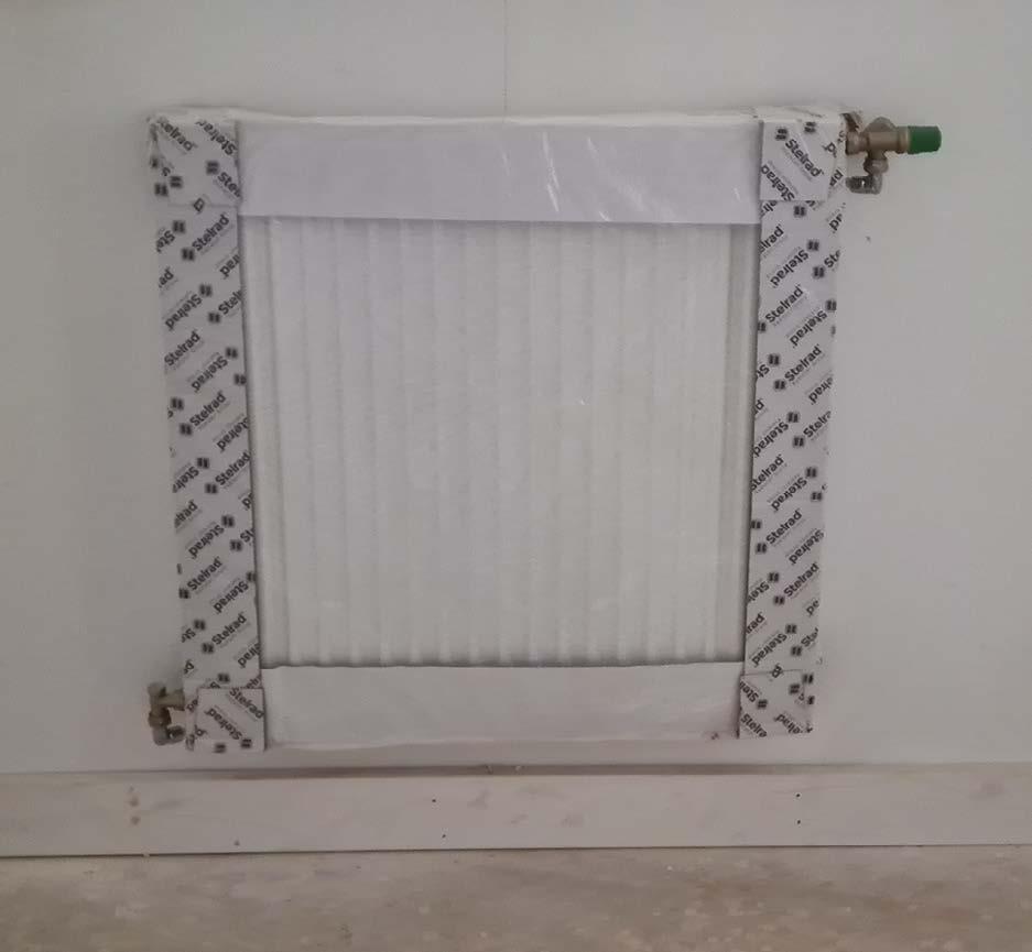
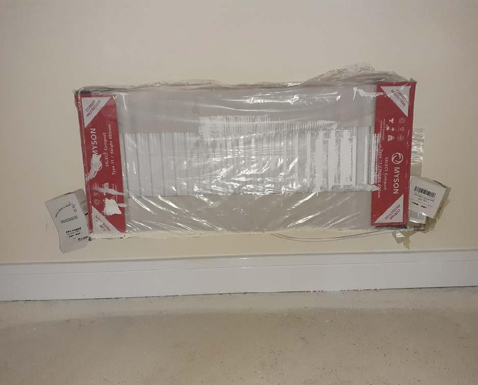
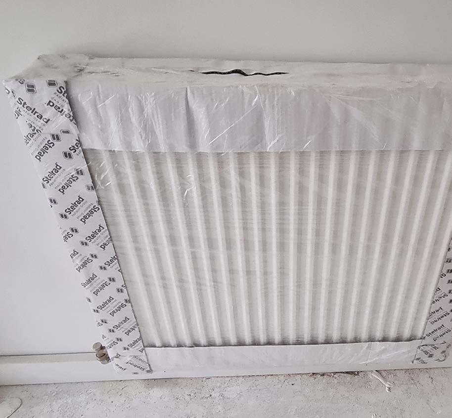
Window boards should be secured with strapping and expanding foam sealed as noted below. For buildings >11m in height, the foam must be a fire-rated product, minimum class A2–s1, d0.
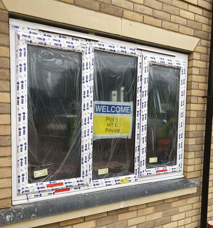
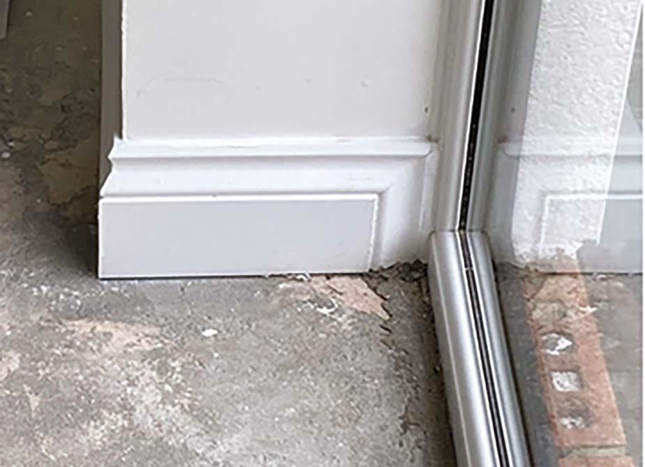
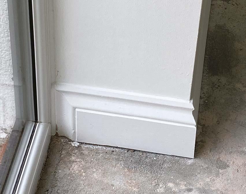
Where specified, the window boards should have consistent returns to each side of all windows within the home. The profile of the return must match that of the front edge (e.g. where a bullnosed window board is installed, the side returns must be bullnosed and finished ready for decoration).
Unless otherwise specified, the window boards should project a minimum of 30-40mm from the face of the finished wall.
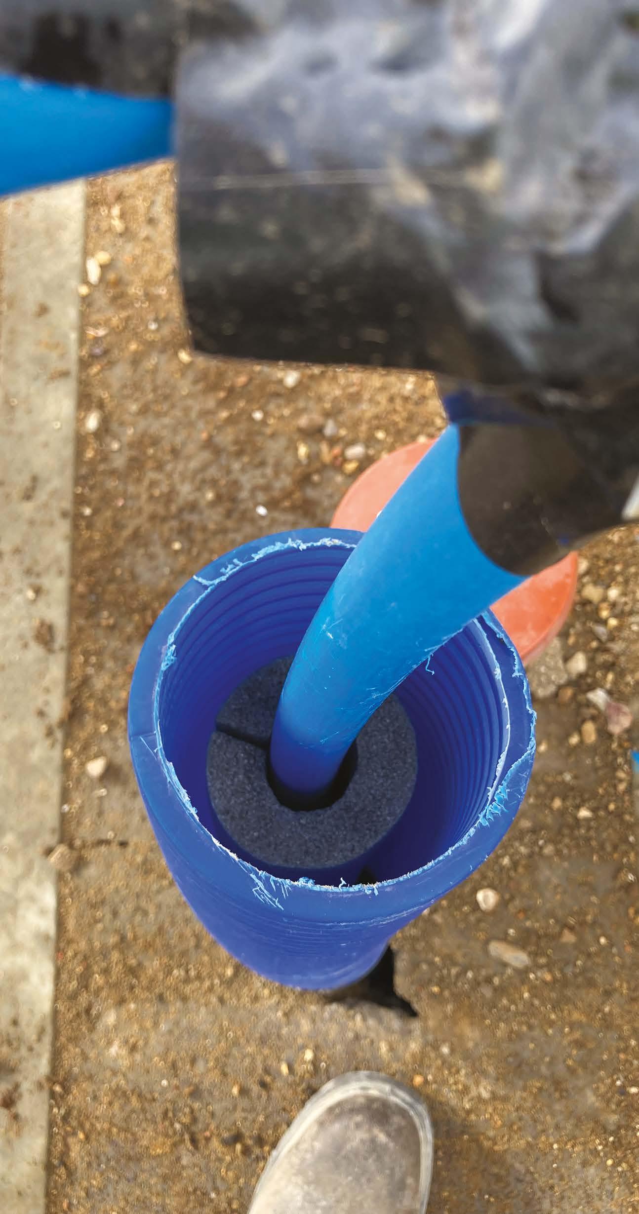
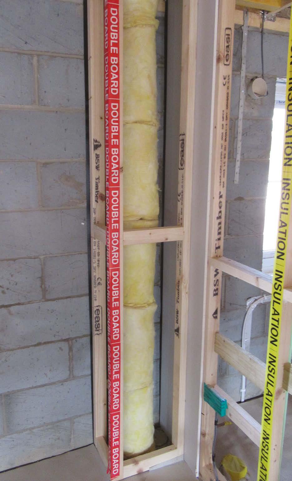
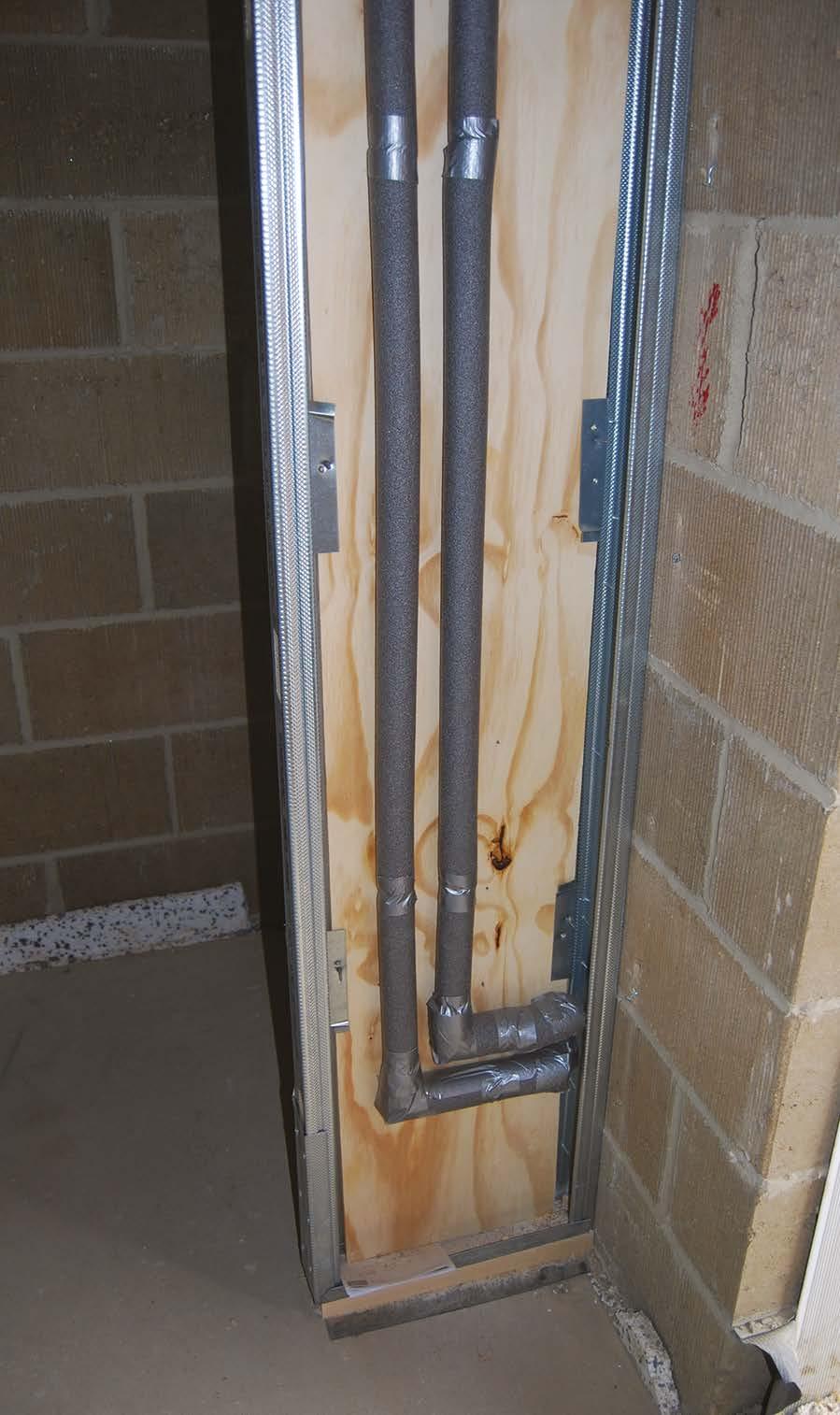
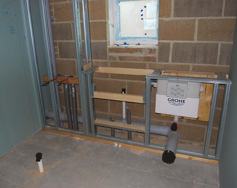
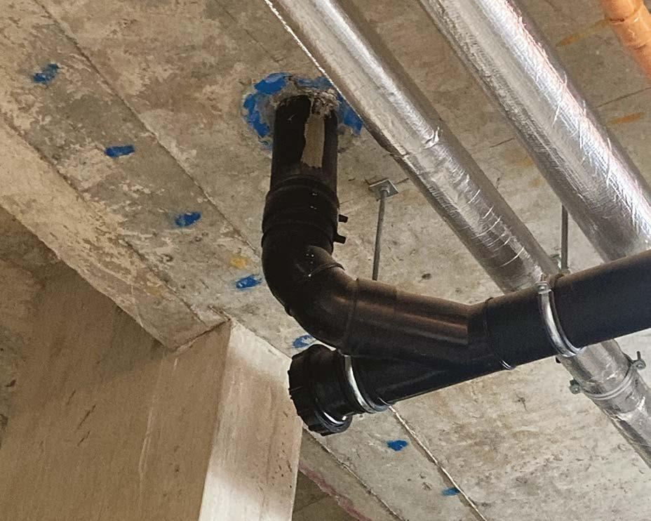
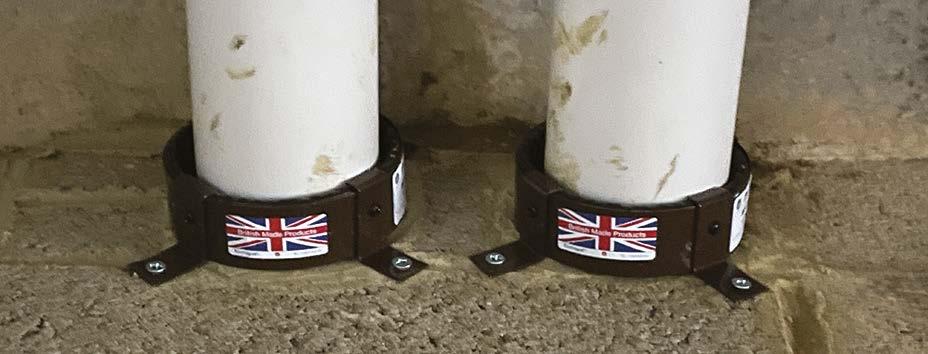
Soil and vent pipes (SVPs) within dwellings should be boxed and wrapped in a minimum of 25mm of unfaced insulation. The boxing should be double boarded to achieve a minimum density of 15kg/ m2. This is required to provide sound insulation and is therefore not needed to sections of SVP that act purely as vents.
Where offsets occur, Hill requires the insulation to be double layered to 50mm.
line
and
the material of the enclosure should have a mass of 15kg/m2
timber framing
the enclosure
wrap the pipe with 25mm unfaced mineral wool (min. density of 10kg/m3)
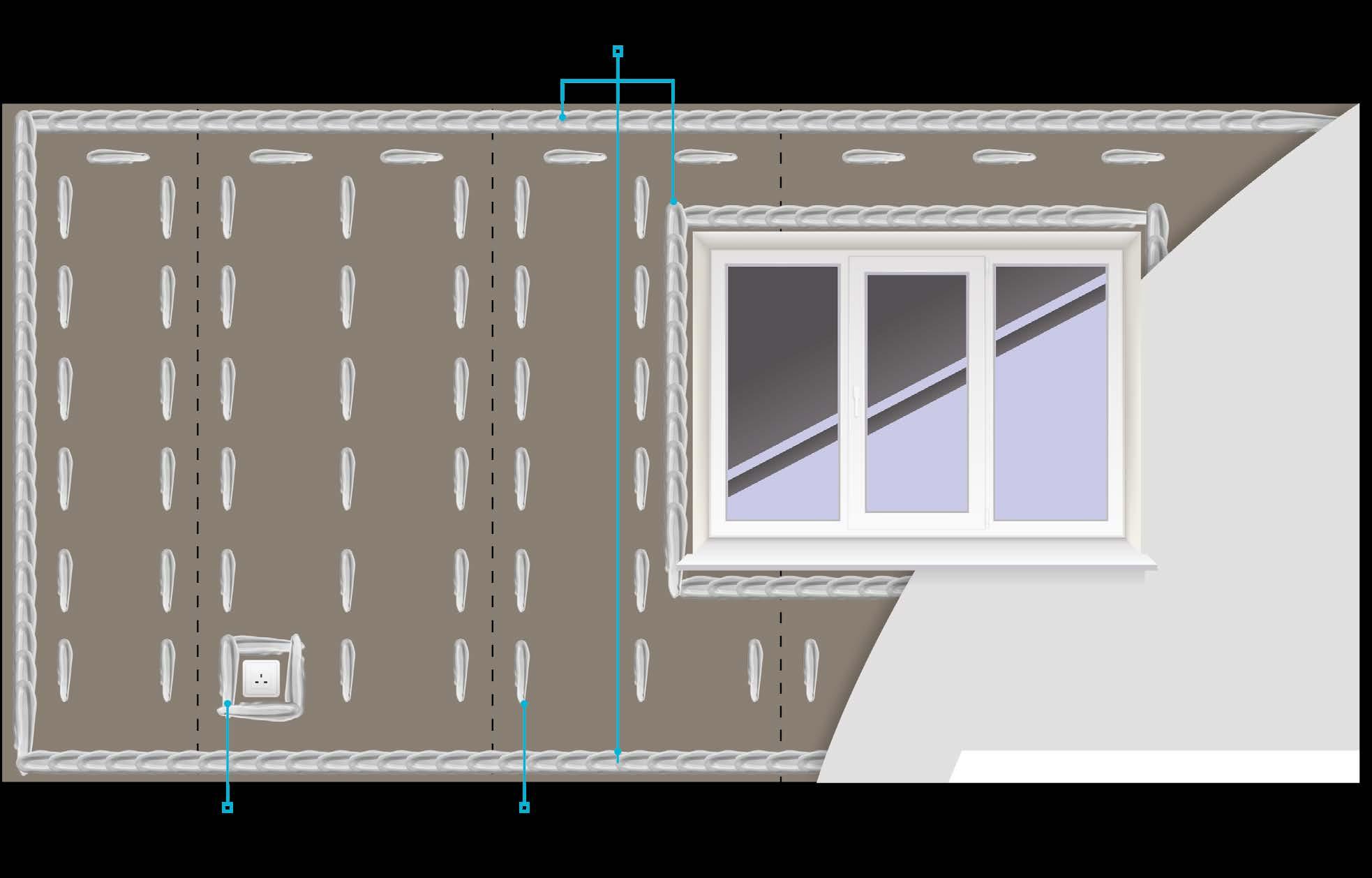
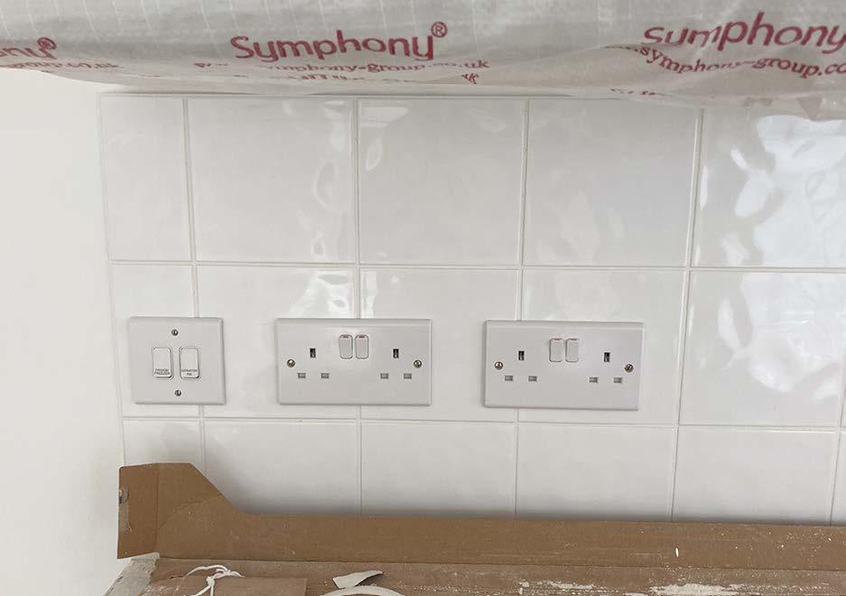
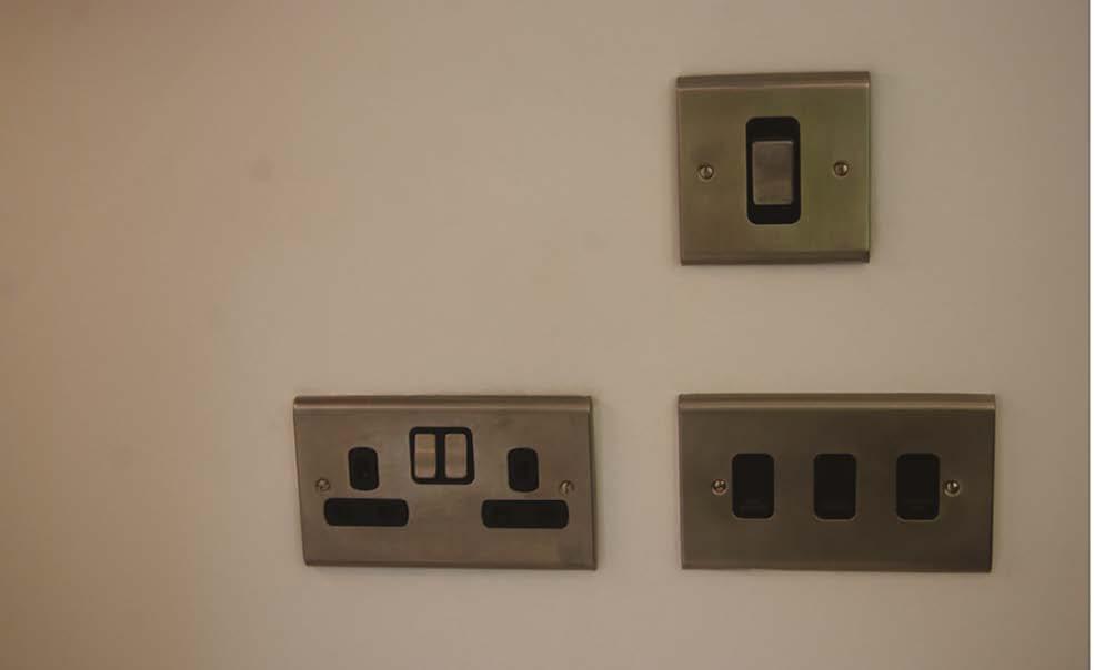
vertically or horizontally to switch or outlet in shaded zone 150mm wide
Diagram
11. First fix (carpentry, M&E services, drylining, fire stopping and windows)
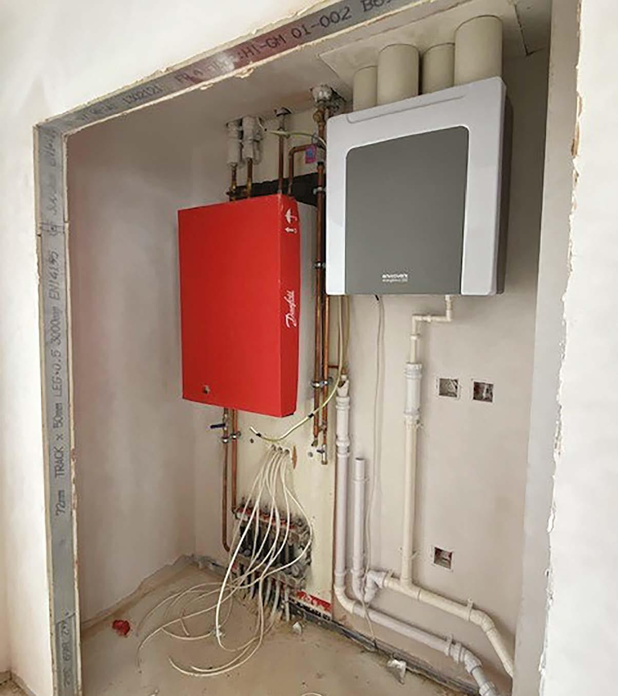
M&E Services
Plumbing and heating
Plumbing and heating pipework shall be installed to a workmanlike standard and take into account all current building regulations, gas regulations, CIBSE (Chartered Institution of Building Services Engineers) and MCS (Microgeneration Certification Scheme) guidance.
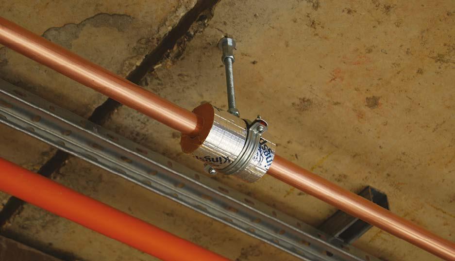
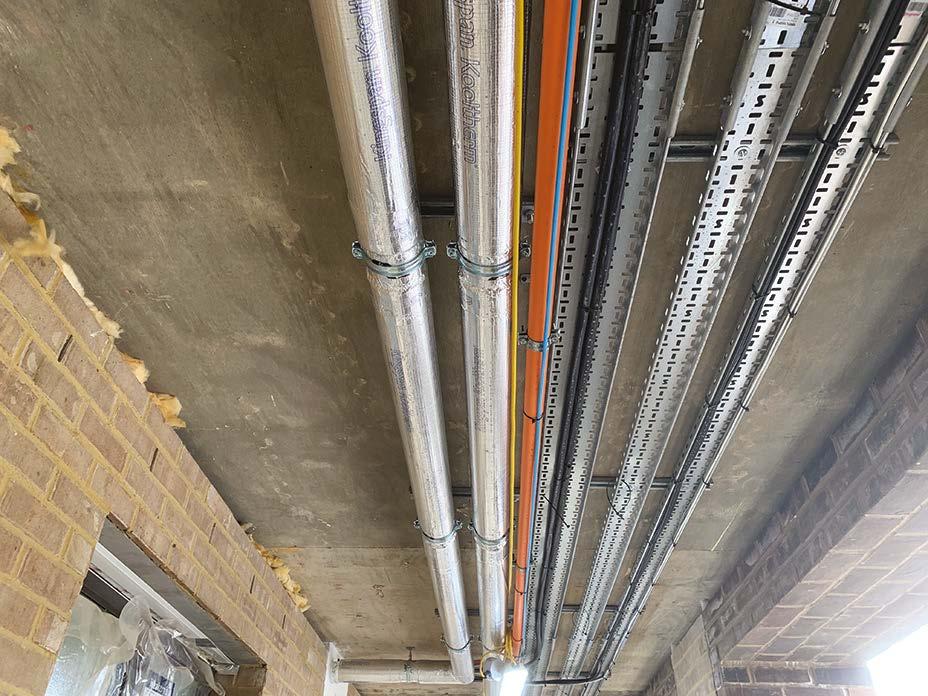
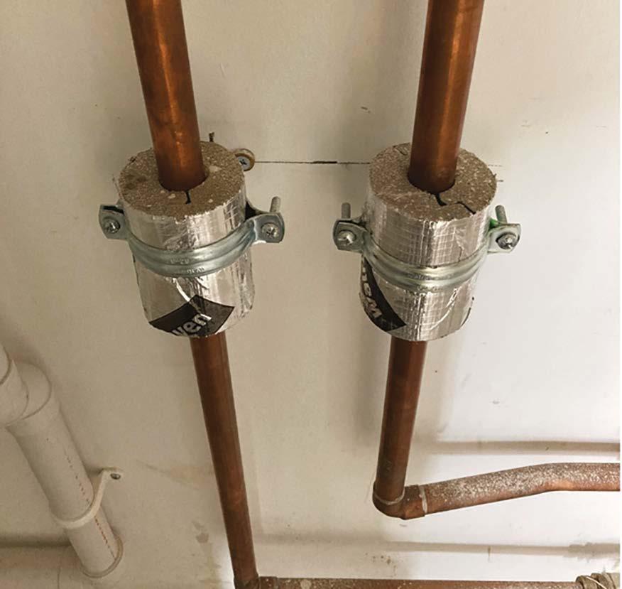
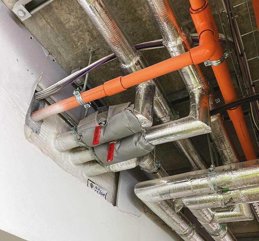
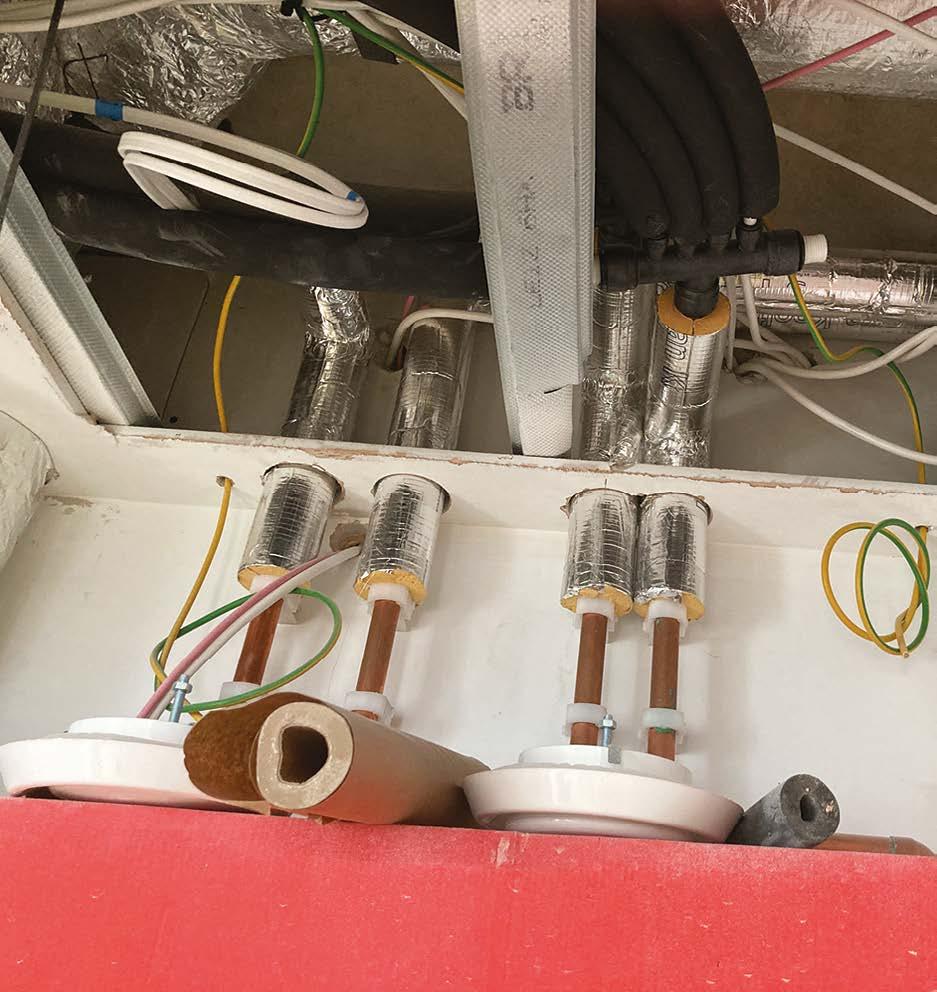
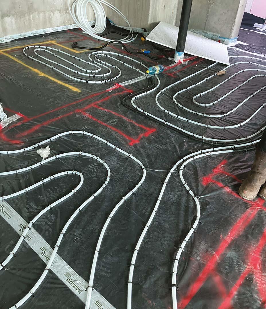
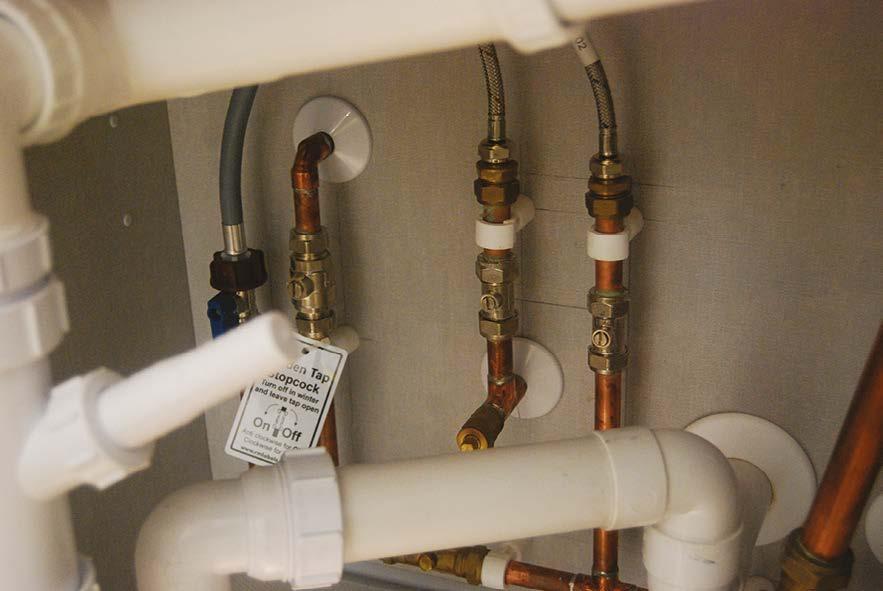
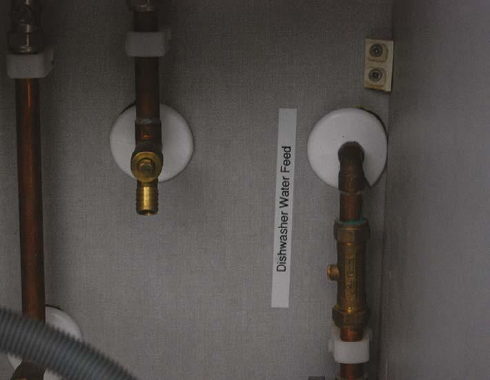
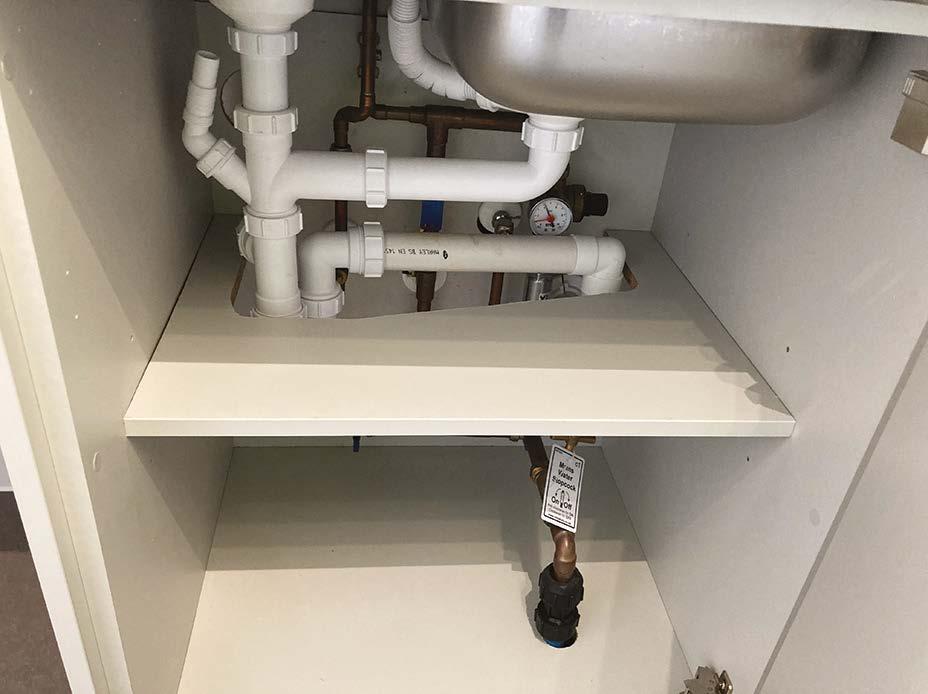
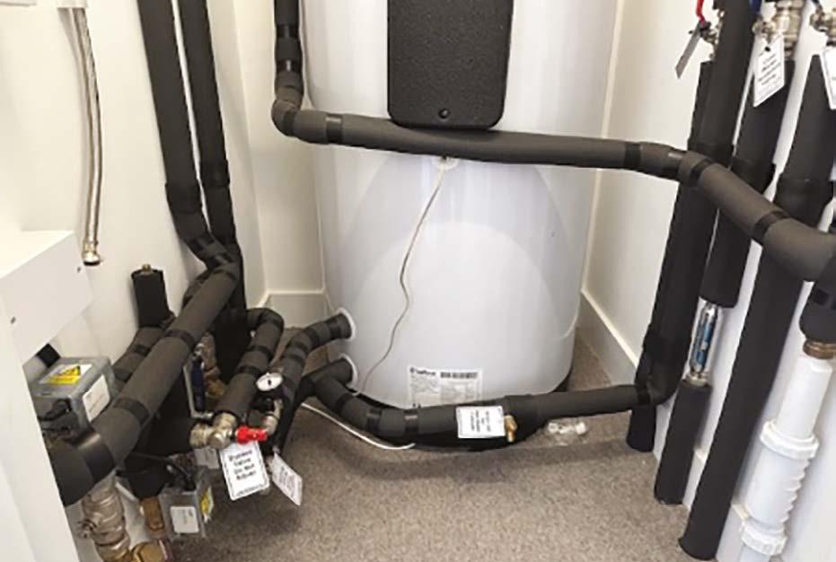
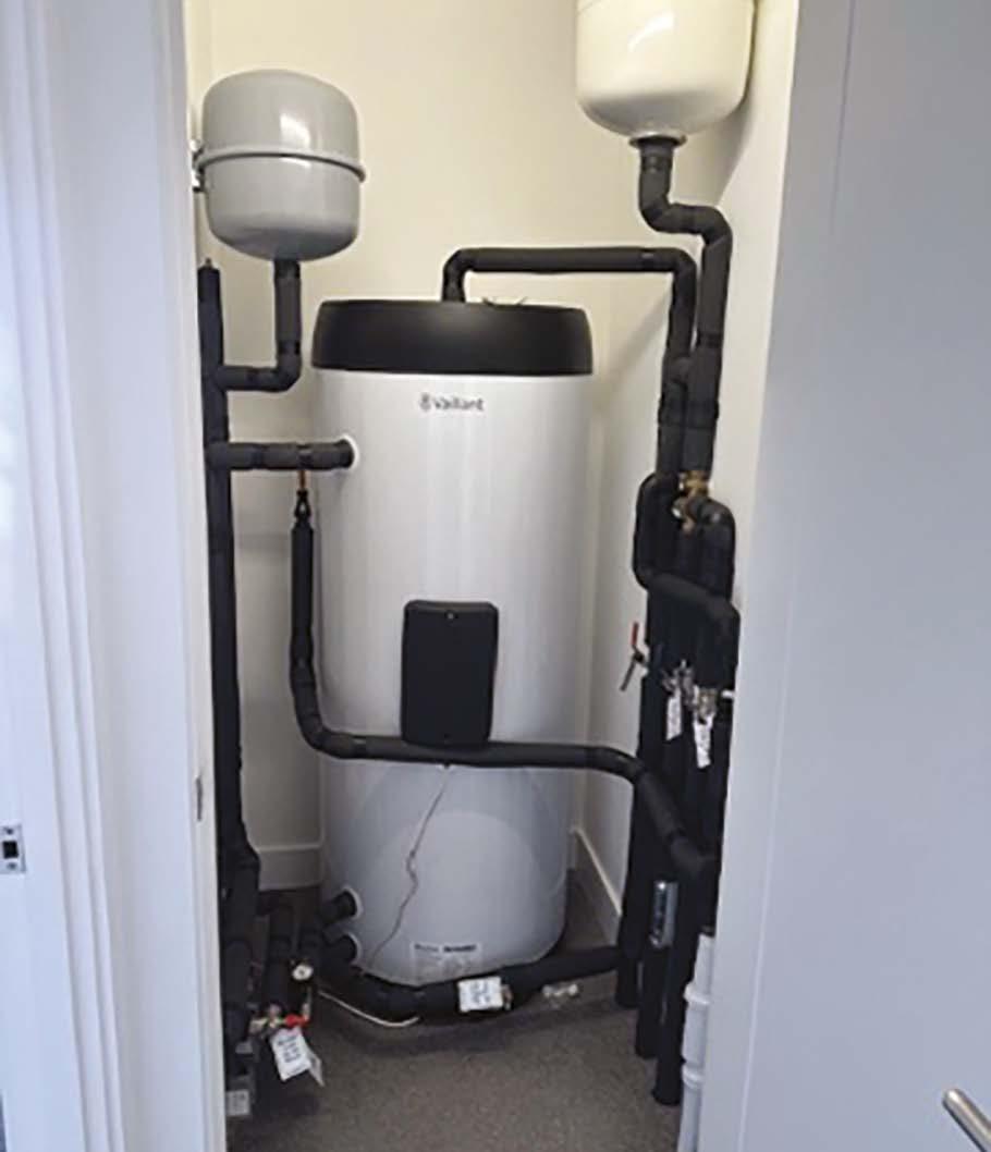
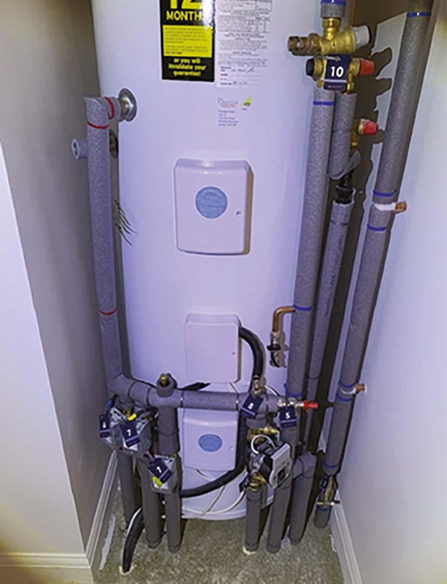
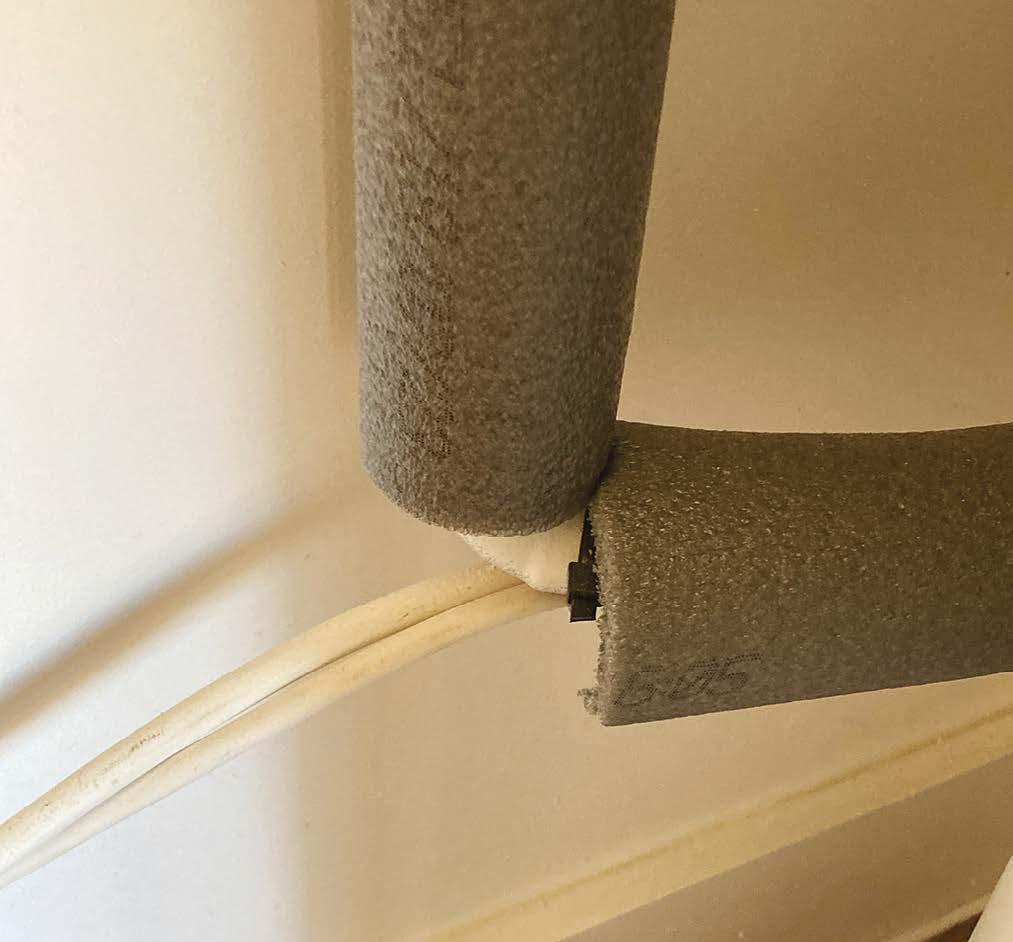
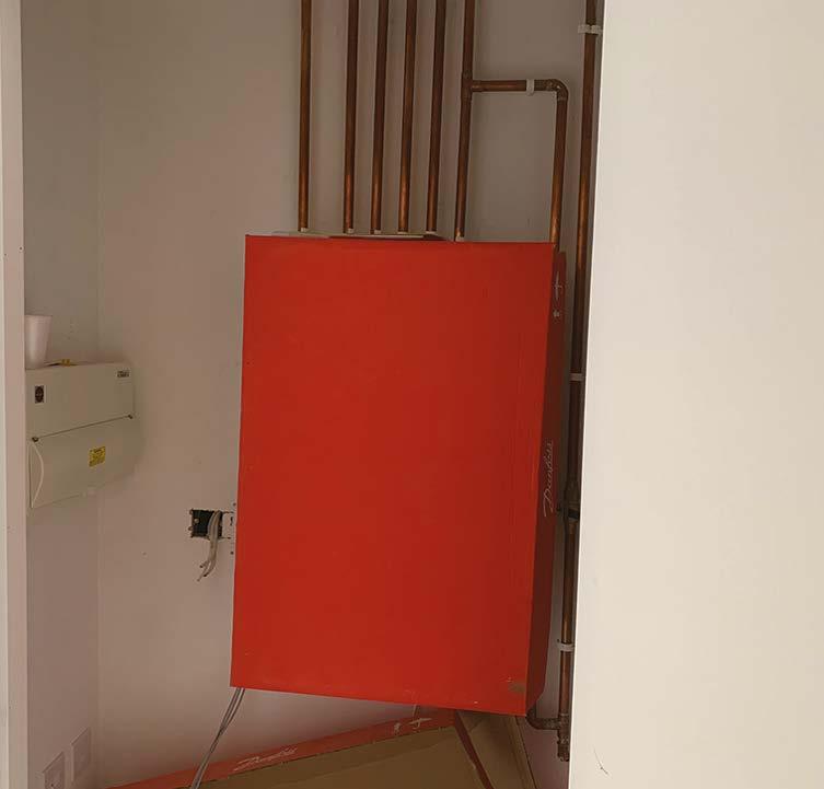
All insulated pipework should be installed in a way that ensures that the insulation remains continuous in its length, including at pipe fixing locations and fittings. Direct clipping of pipes should be avoided, as this introduces a break in the insulation at every clip. NHBC Standards 2024 now require all pipework in intermediate floors to be fully insulated including valves and fittings.
these images, care has been taken to install a neat pipe and cable support system.
this
care
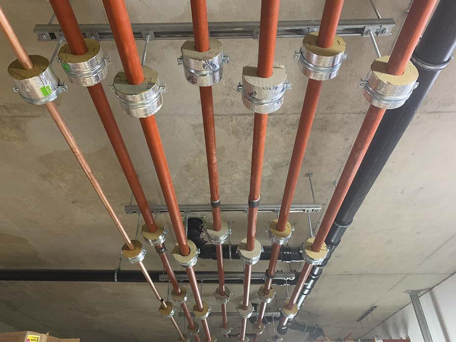
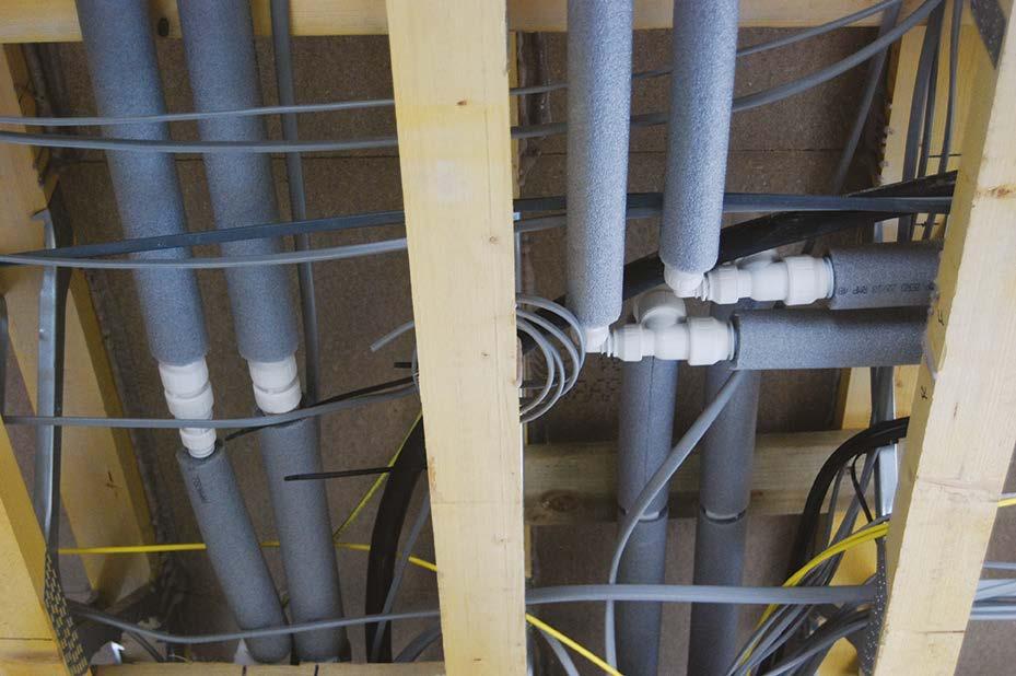
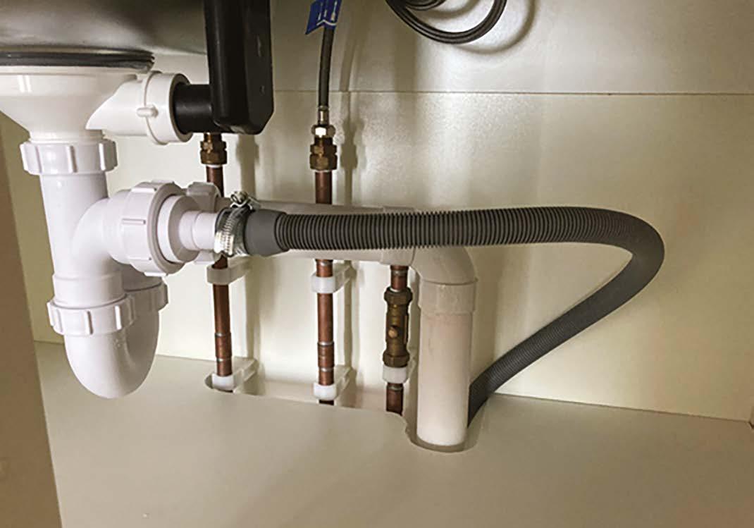
Good examples of pipes supported by the clipping of the insulation using munsen rings, oversized pipe clips or waste pipe clips are shown below. This is also important on cold water pipes to maintain a continuous vapour barrier to avoid condensation.
In
In
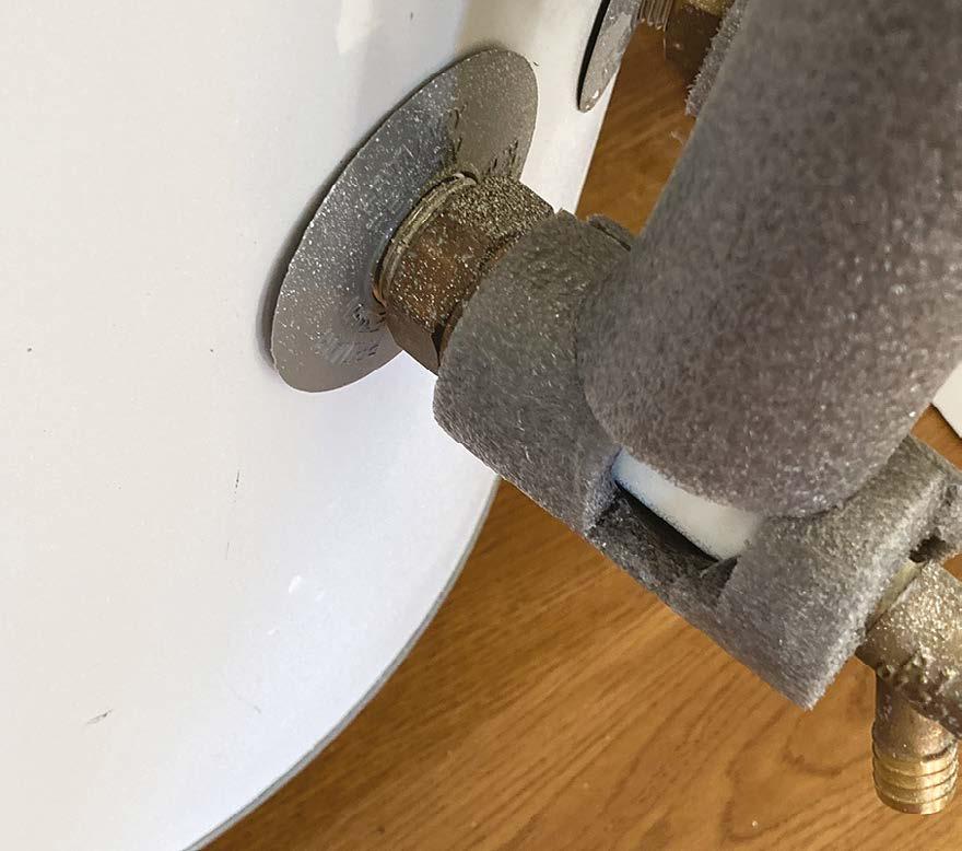
image,
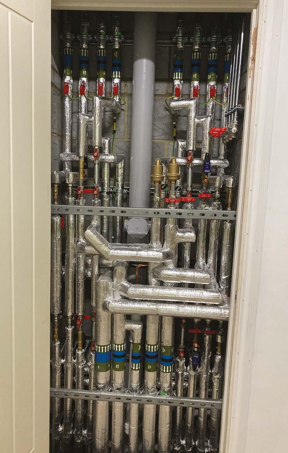
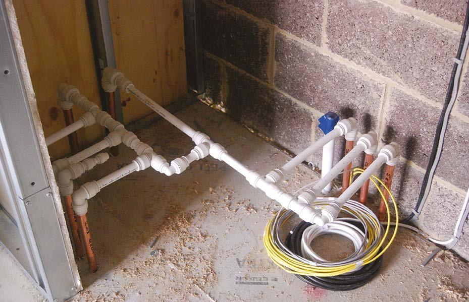
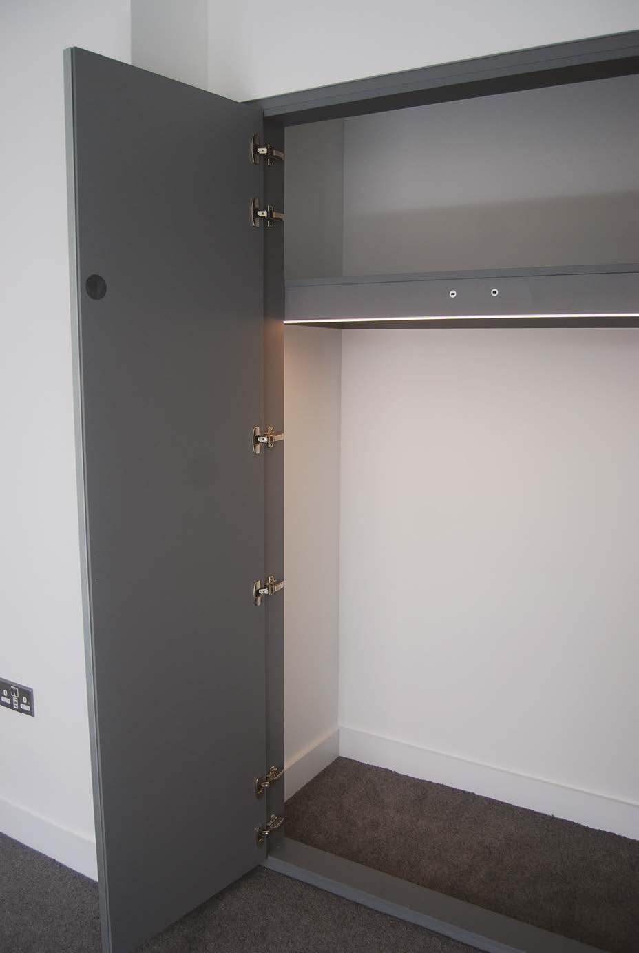
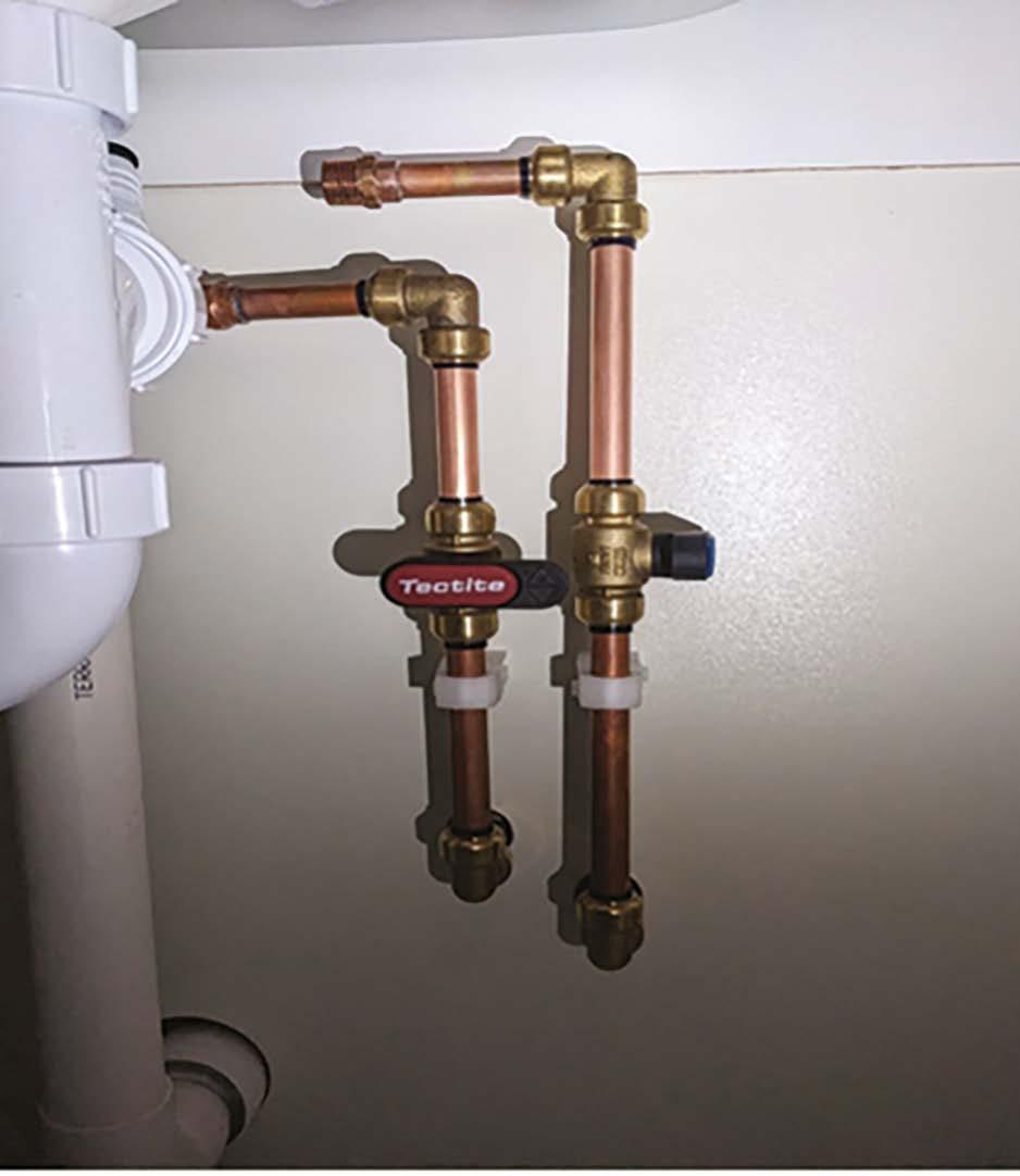
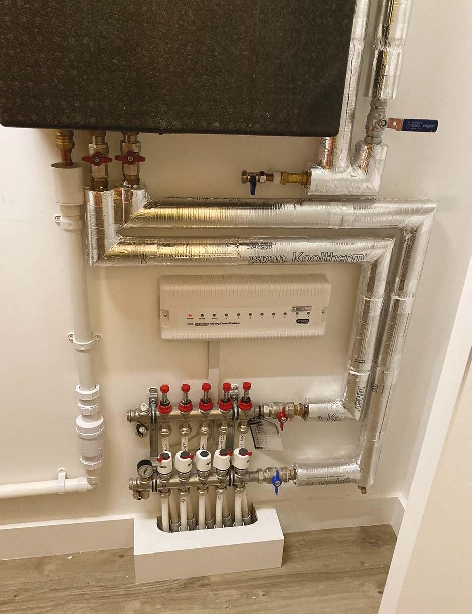
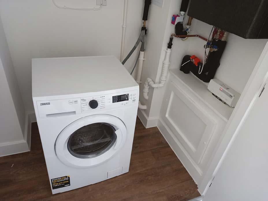
has been taken to maintain the insulation at wall pipe supports within a utility cupboard.
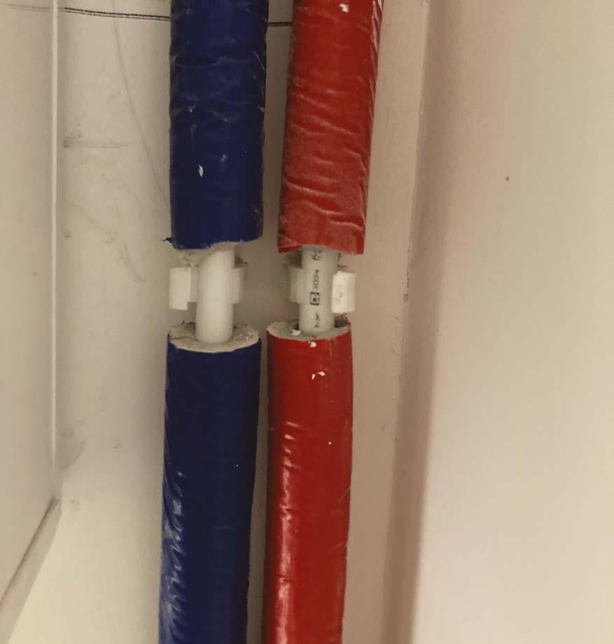
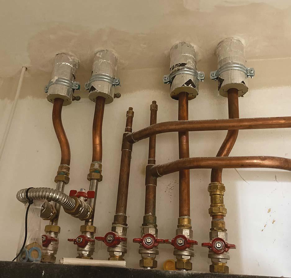
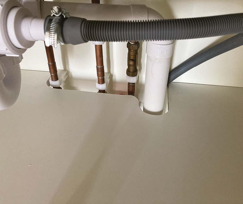
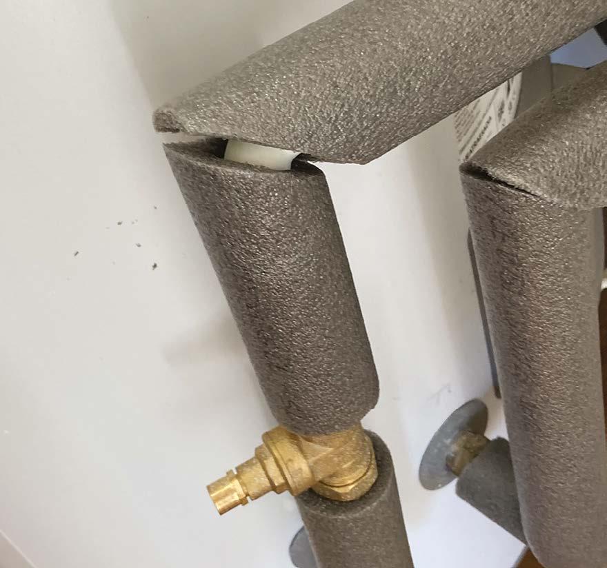
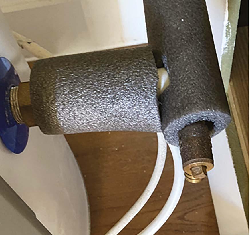
This is unacceptable. The pre-insulated pipe is cut at every pipe support location.
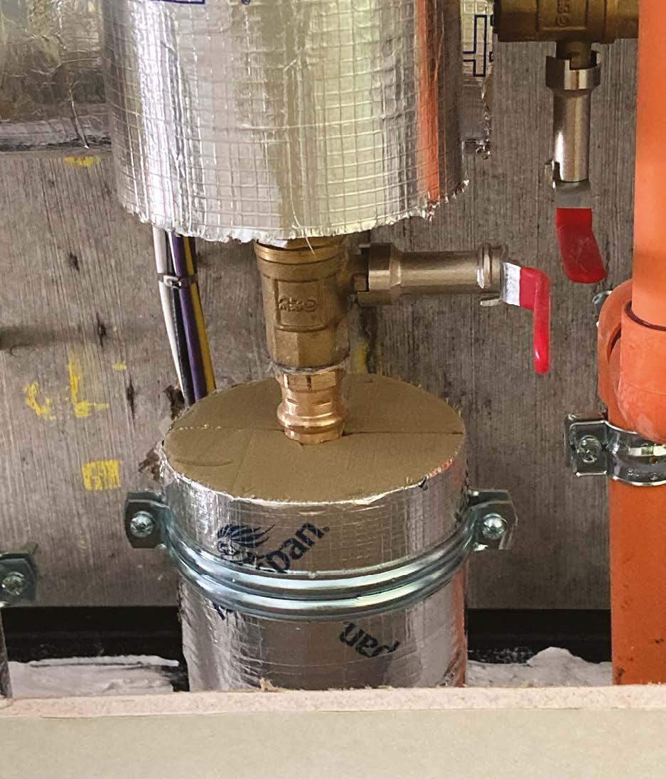
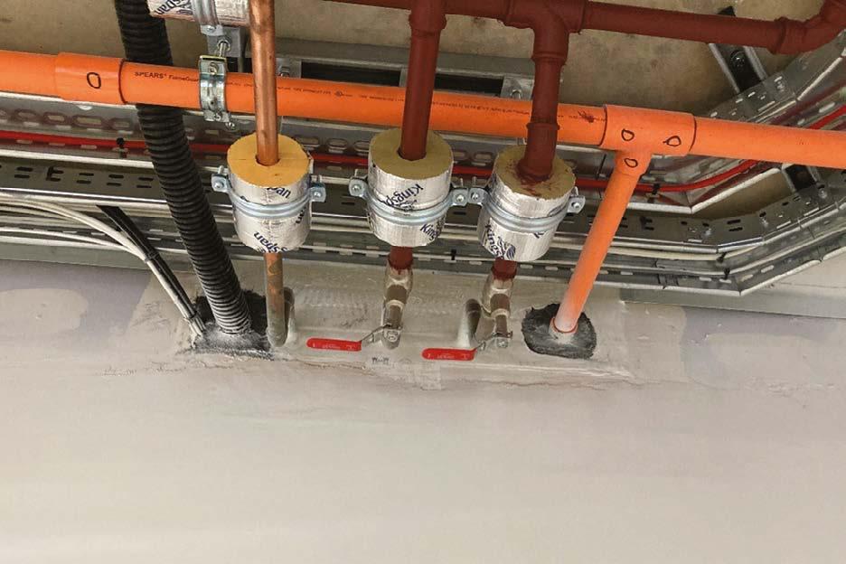
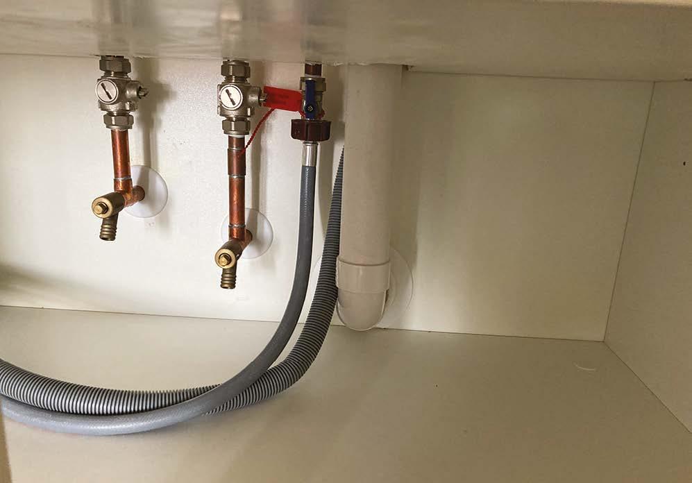
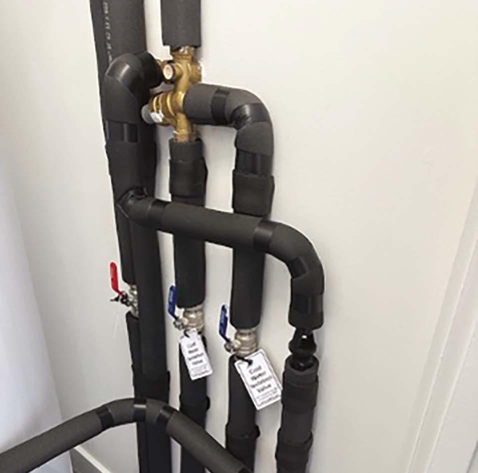
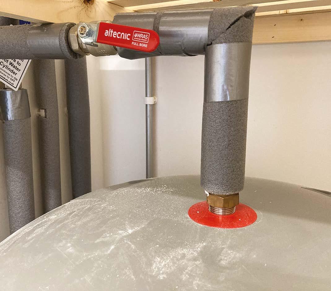
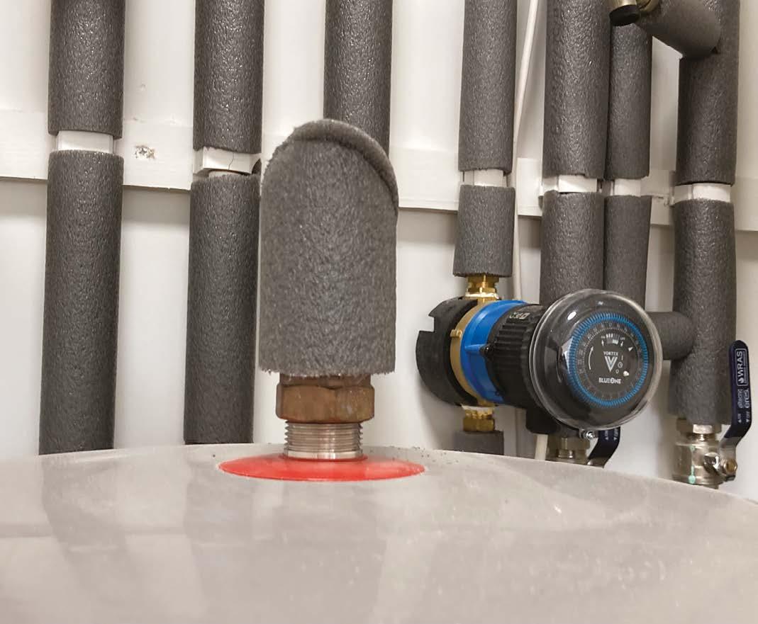
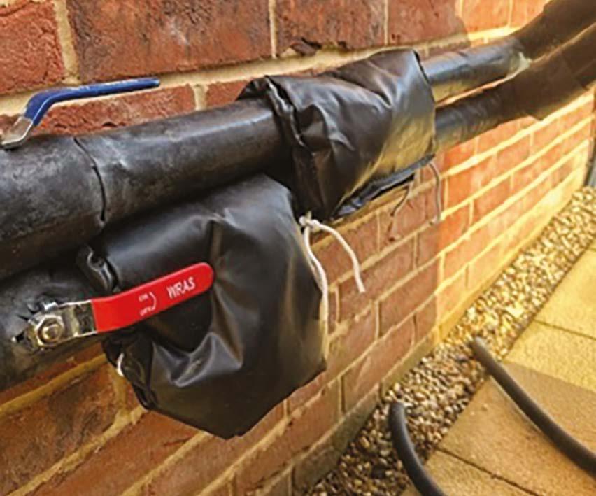
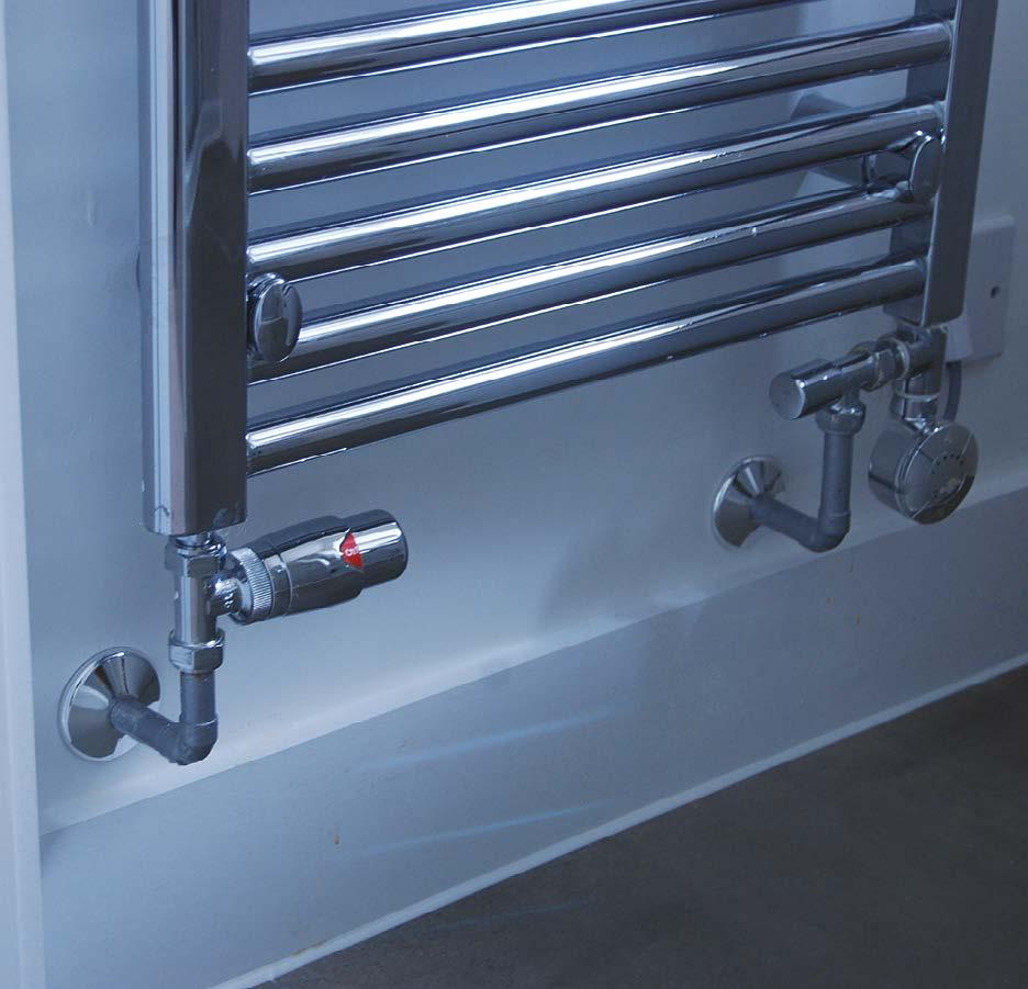
Long stem valves (or extension stems) should be installed where insulation thickness might otherwise have to be cut to accommodate a standard valve lever.
In this example, proprietary, insulated valve jackets have been used to maintain continuity of insulation through the valves.
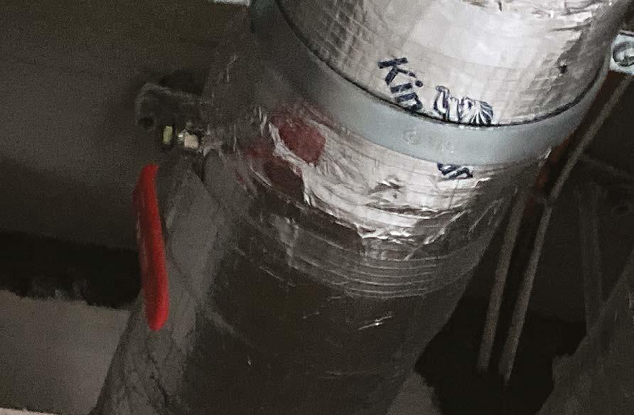
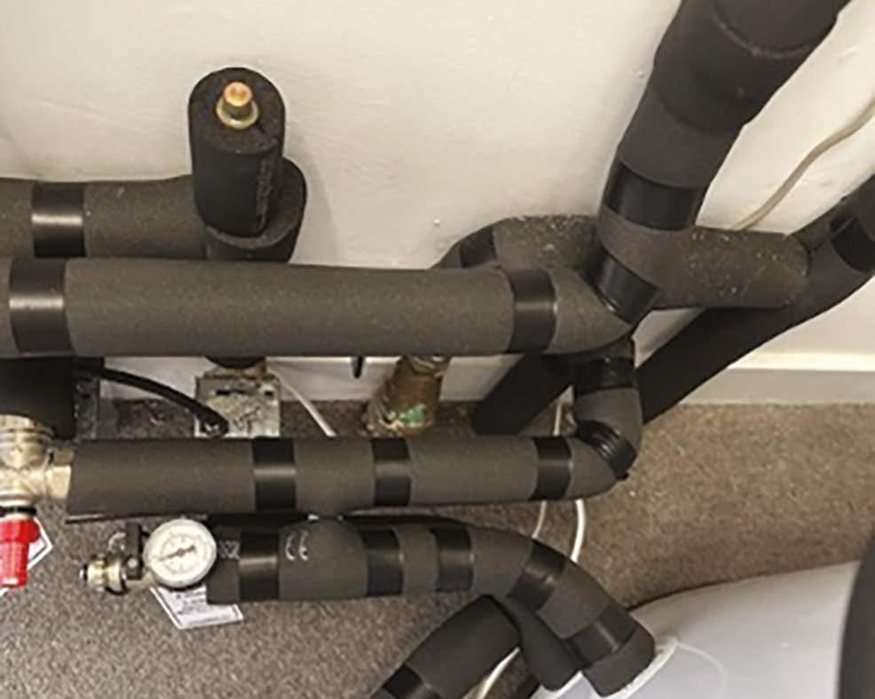
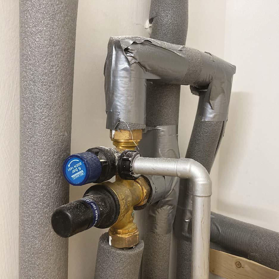
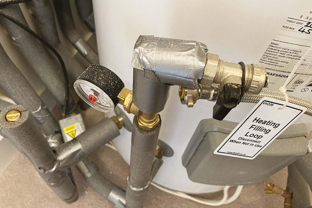
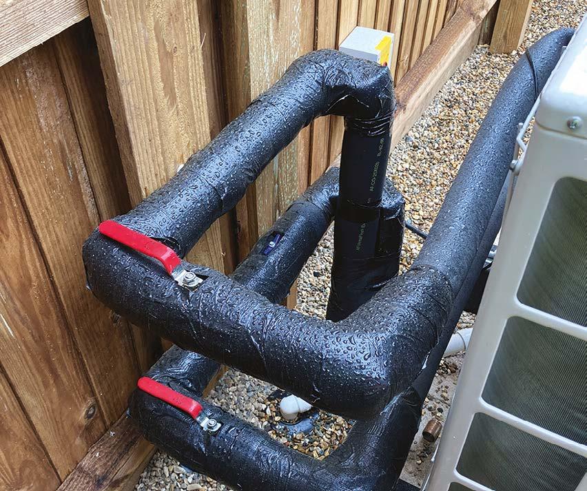
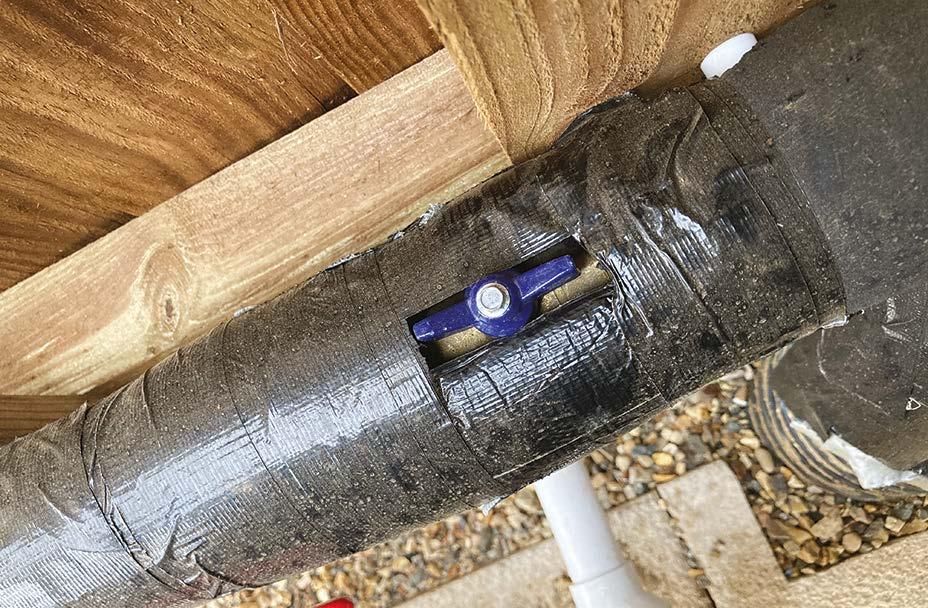
Below photos is a good example where effort and care has been taken to insulate the entire pipe run, including fittings. Duct tape should however not be used, as it dries out over time and falls off.
11. First fix (carpentry, M&E services, drylining, fire stopping and windows)
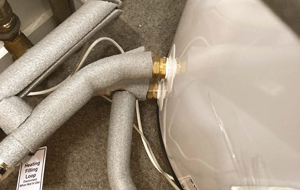
In this image, no attempt has been made to insulate the pipe fittings, some of which have electrical cables in contact with hot pipes (which must never be allowed to happen).
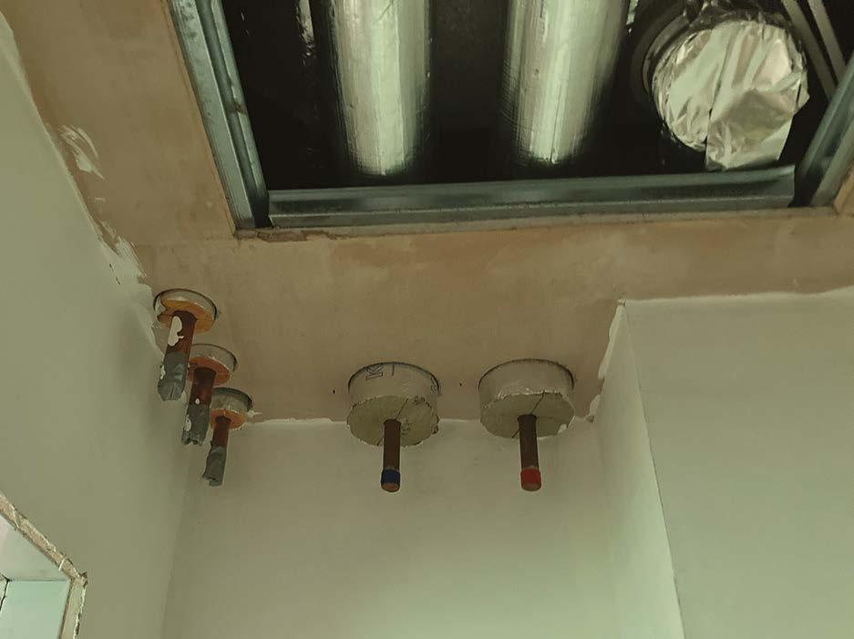
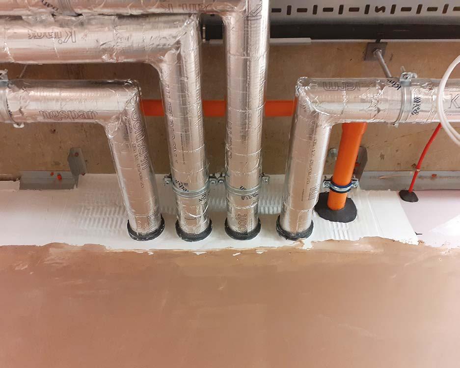
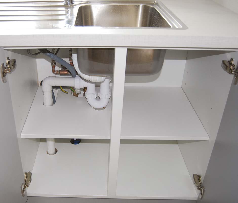
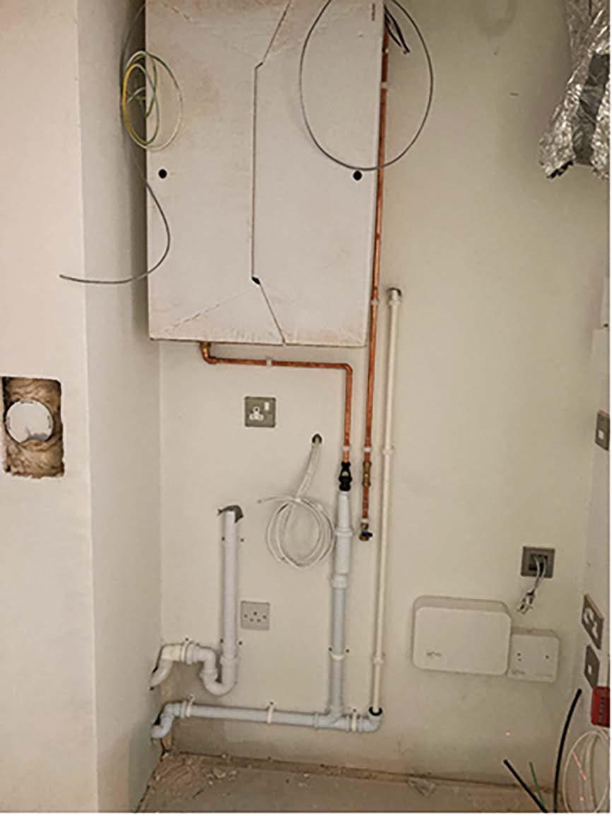
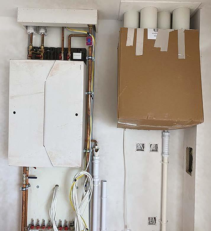
Neatness and excellent setting out is required and evident here.
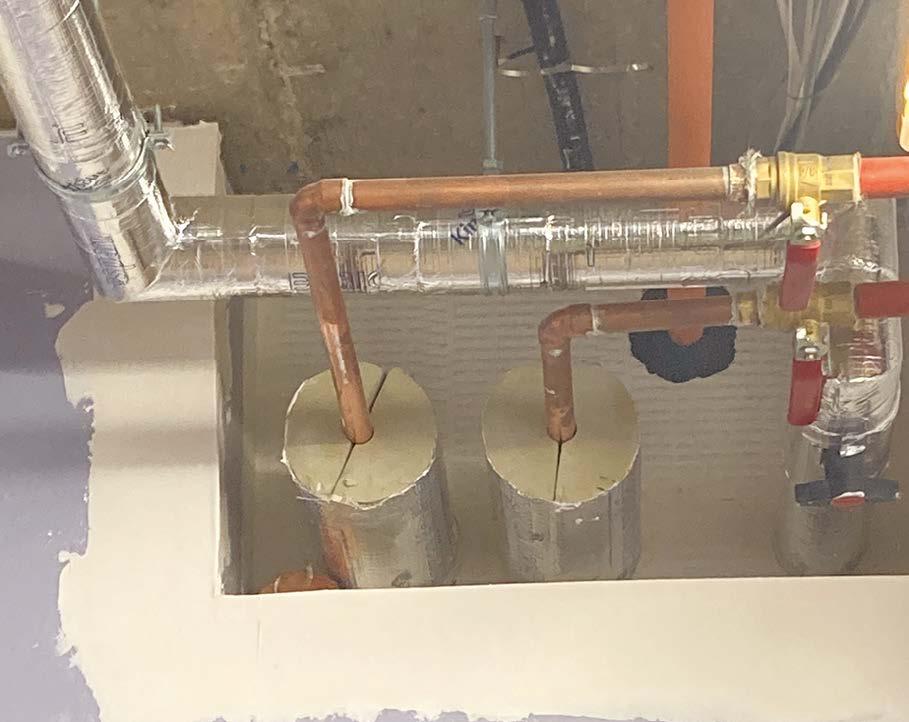
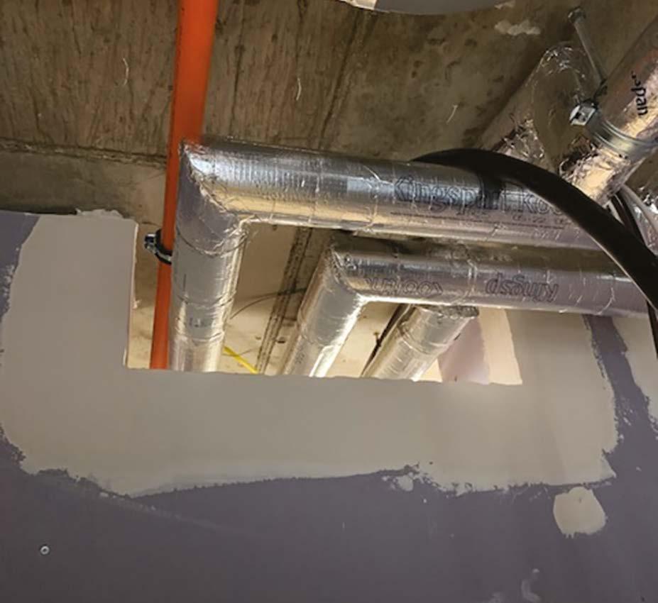
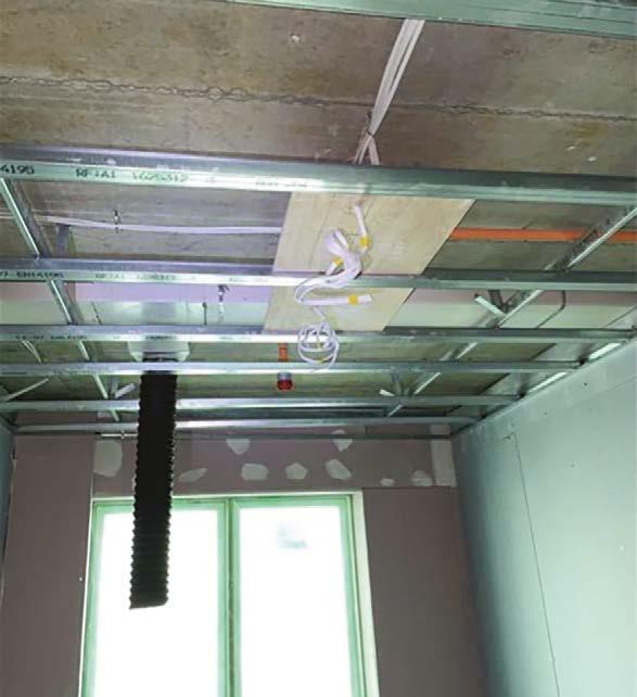
This demonstrates the foresight and care taken by the dry liner and plumber to install a rip of plastered ceiling board ahead of the plumbing installation to maintain a neat finish when the pipes are subsequently drilled and installed. The pipe insulation is maintained throughout the penetration.
Here we have an improvement on the previous photograph as the pipework is supported using munsen rings wrapped around the insulation.
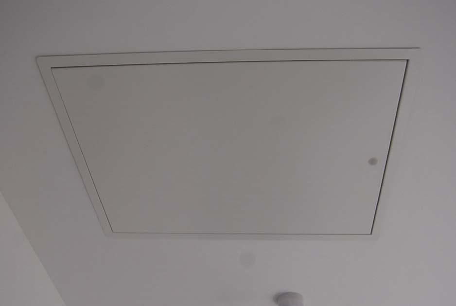
This is a similar scenario, but it incorporates a ceiling access panel and very thick pipe insulation.
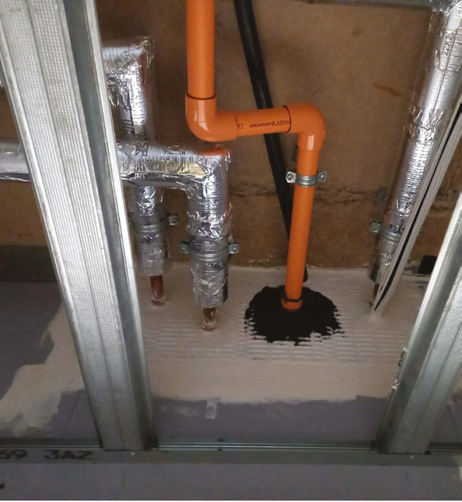
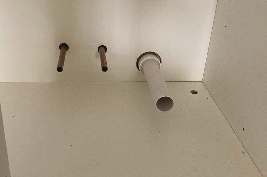
The pipes are all temporarily capped or sealed to prevent contamination – something that should always be done to pipes, drainage and ventilation ducts.
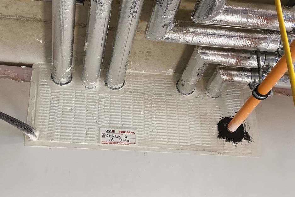
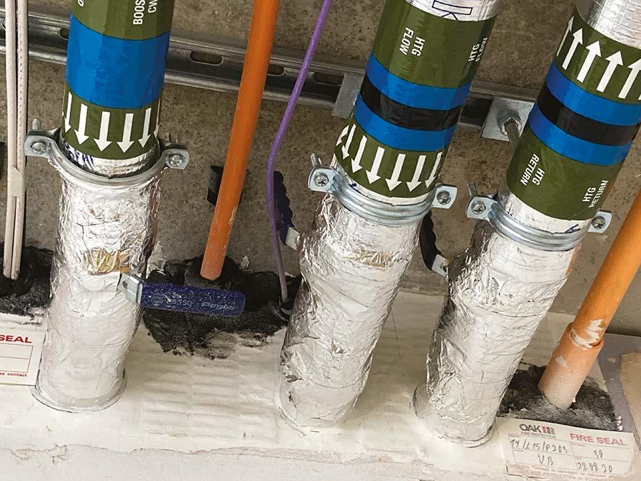
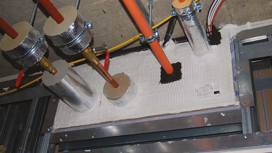
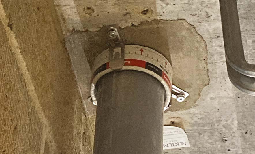
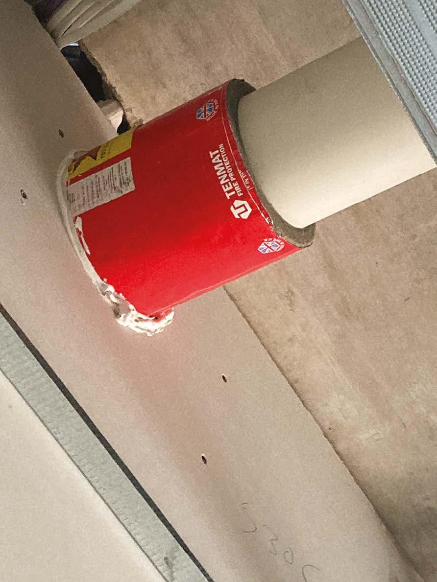
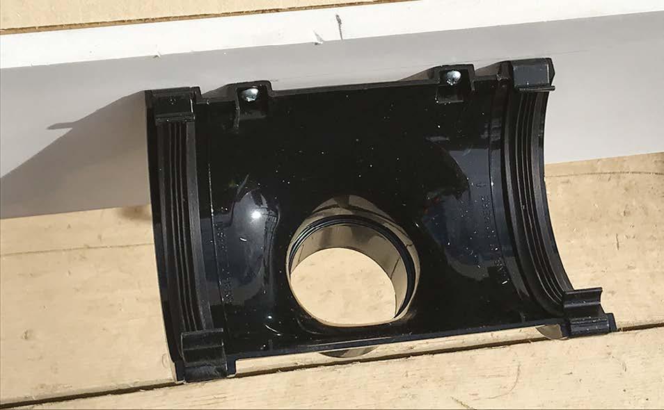
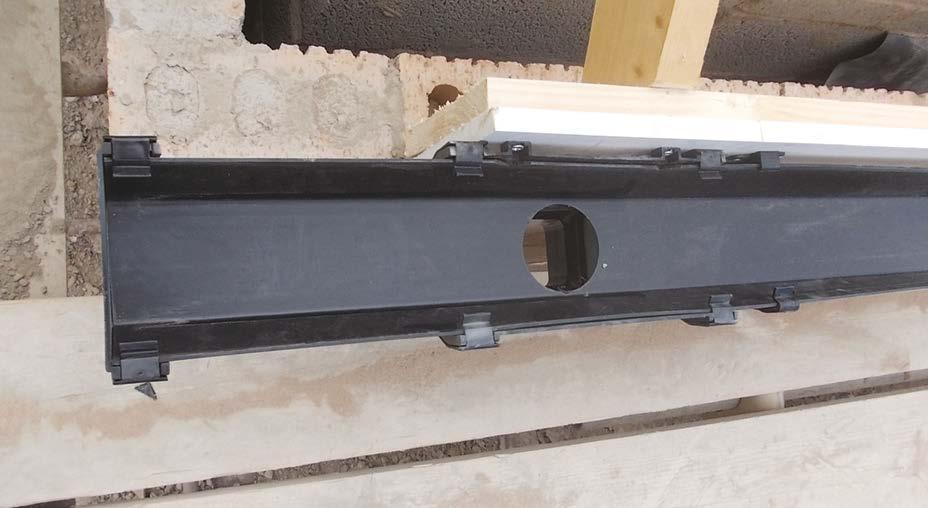
In these images, the pipe insulation has been correctly run continuously through letter box openings that form the fire compartmentation. An intumescent fire wrap will seal any combustible insulation (if used), or a gap seal will seal against any stonewool insulation used.
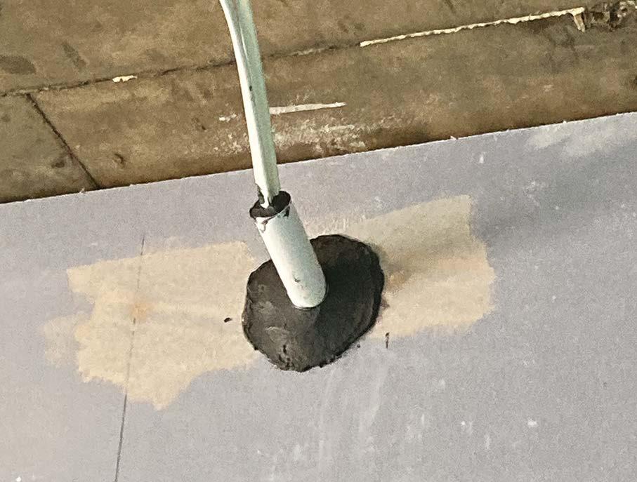
In this image, the pipe insulation has incorrectly not been run continuously and stops either side of the fire bat.
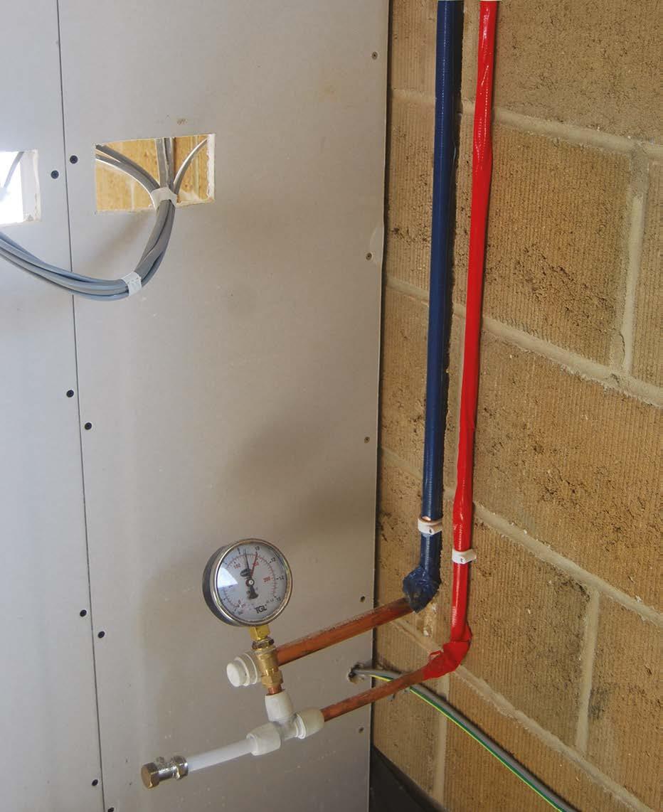
Testing of pipework
All pipework should be pressure-tested -in accordance with the specification / pipe manufacturer’s instructions. This should be recorded on the Hill QA system.
11. First fix (carpentry, M&E services, drylining, fire stopping and windows)
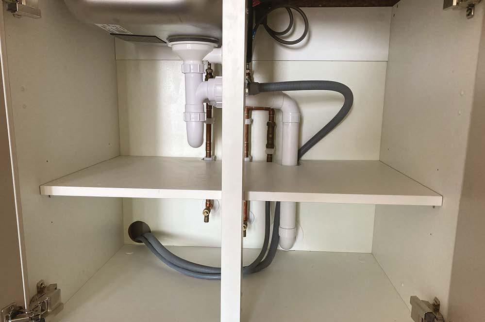
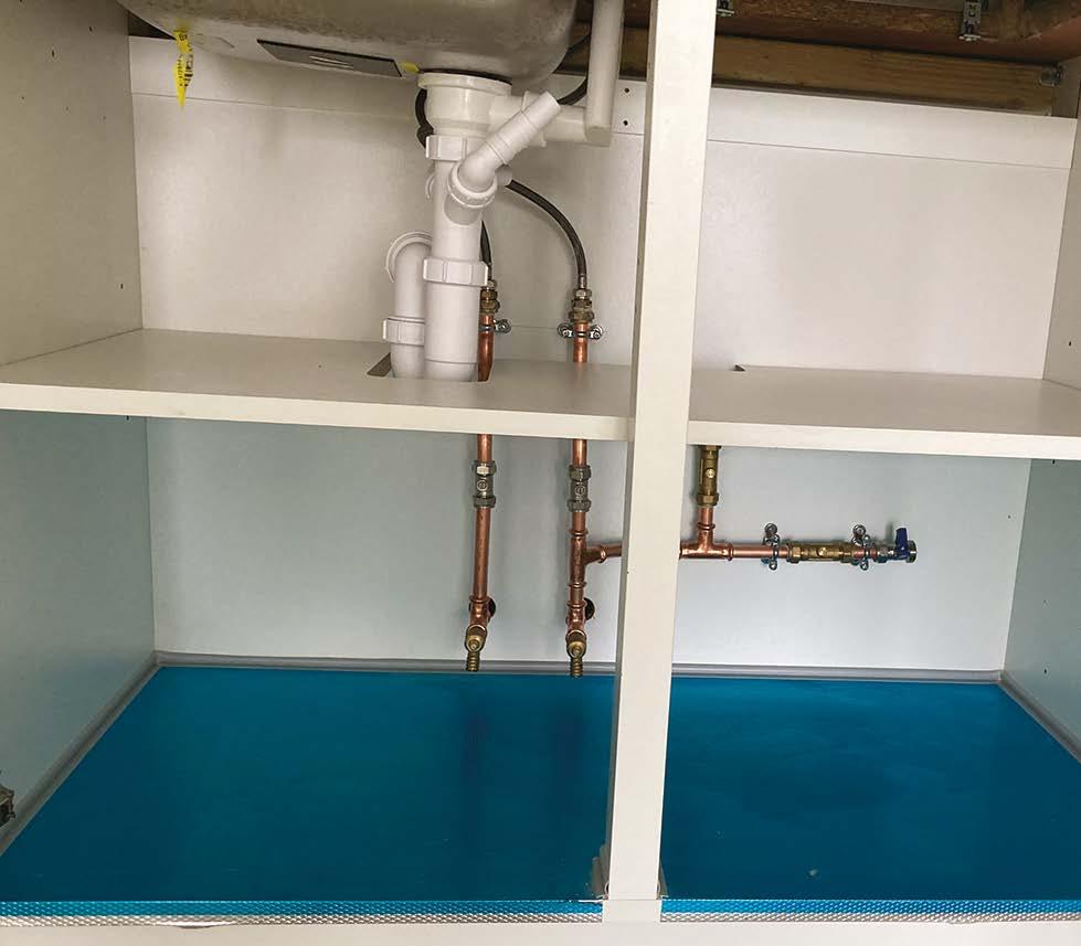
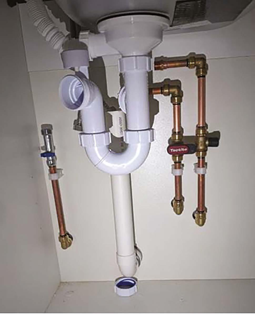
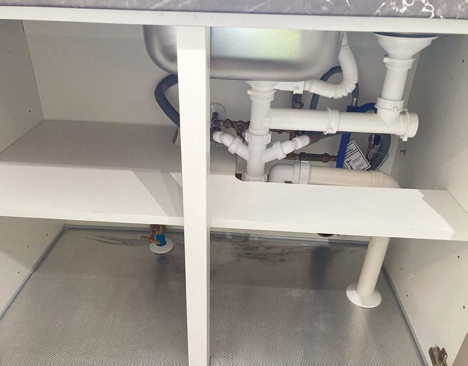
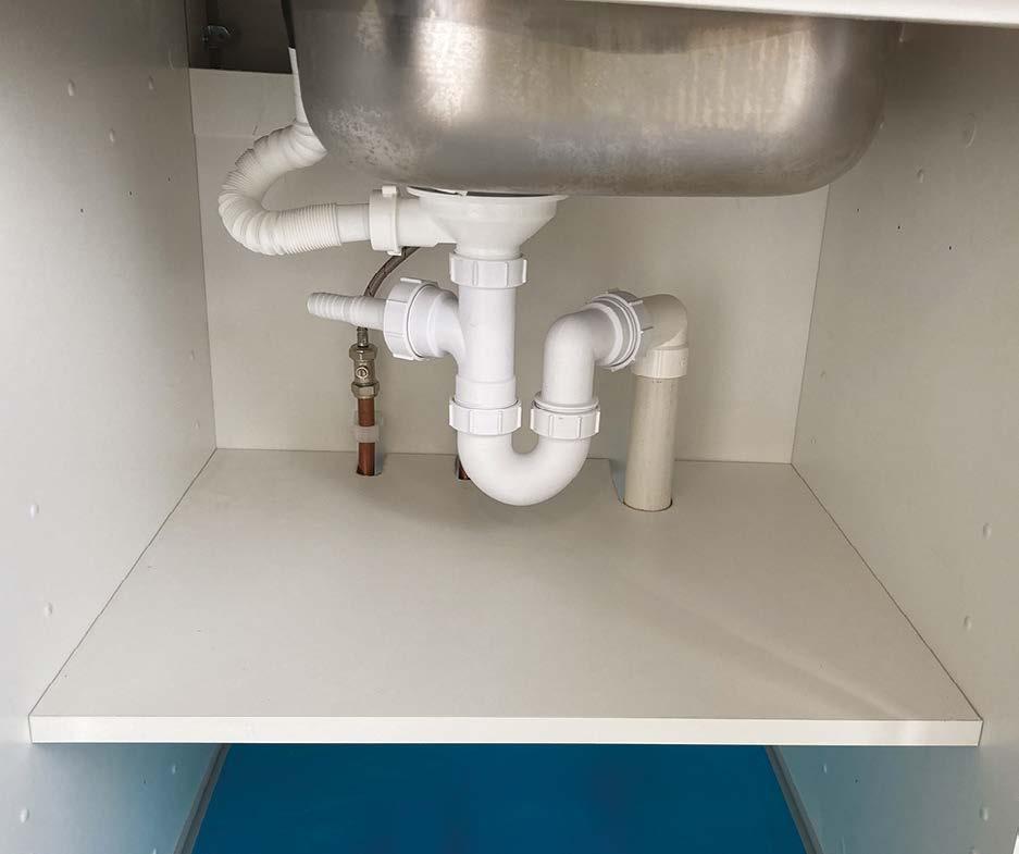
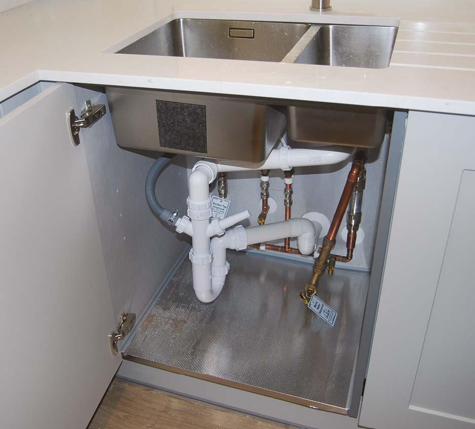
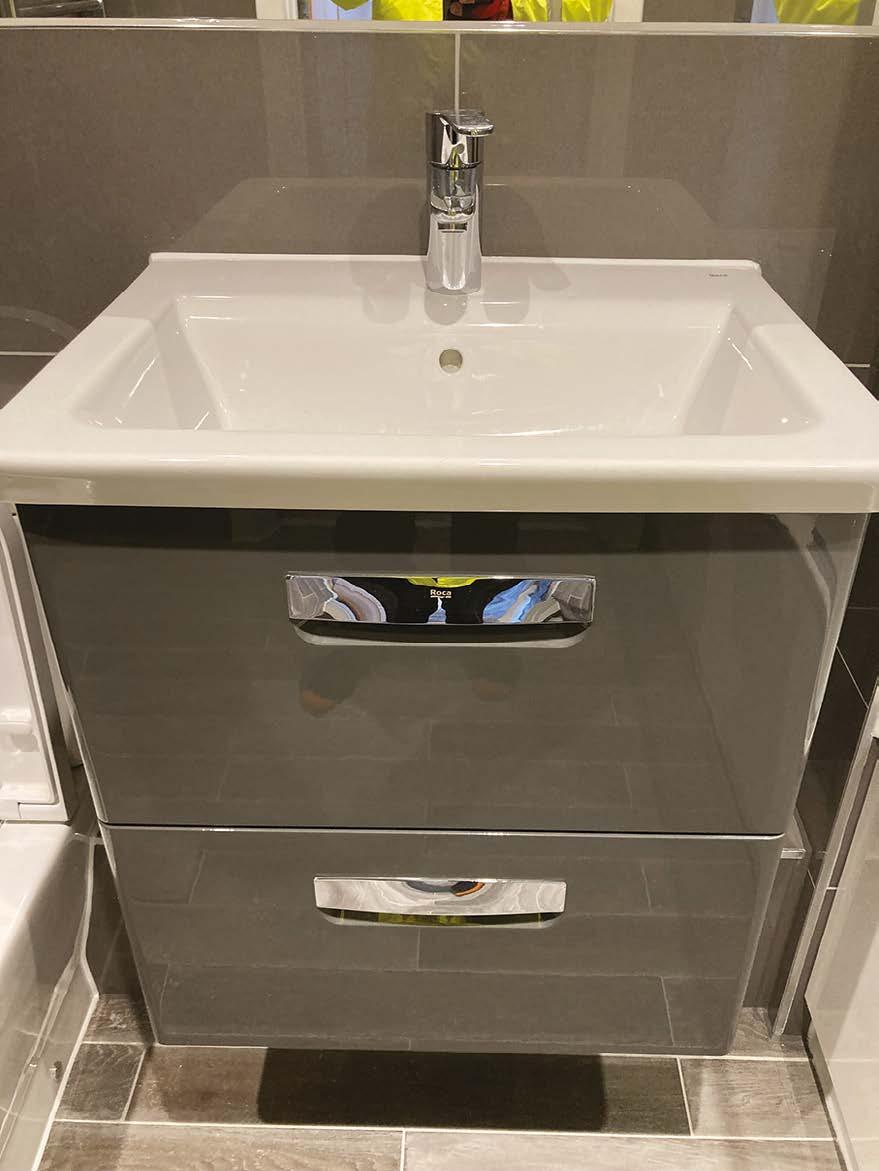
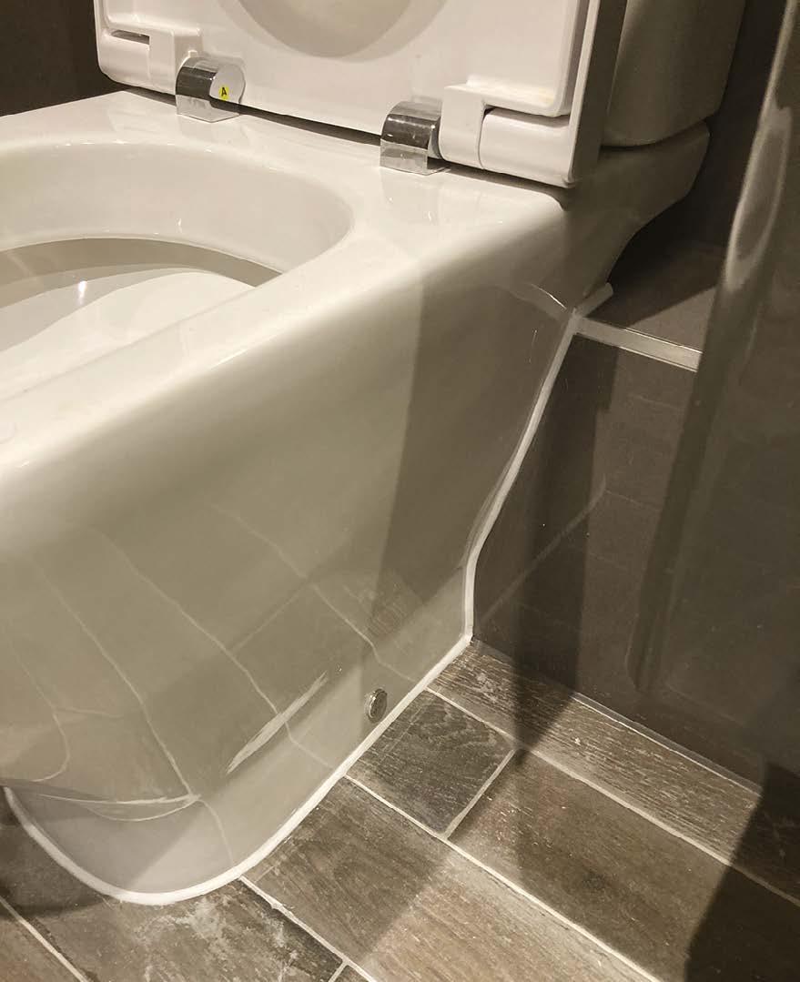
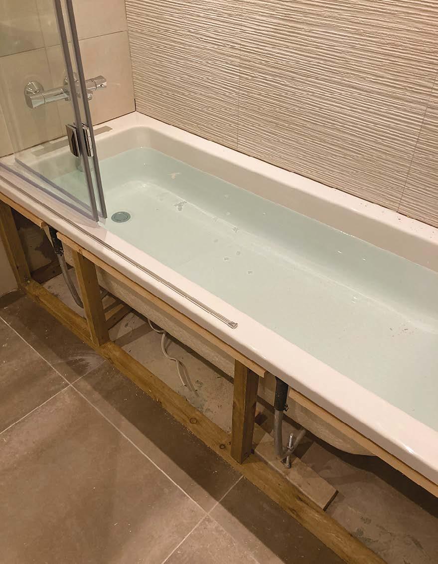
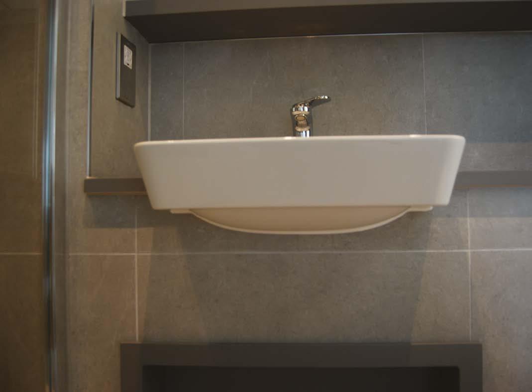
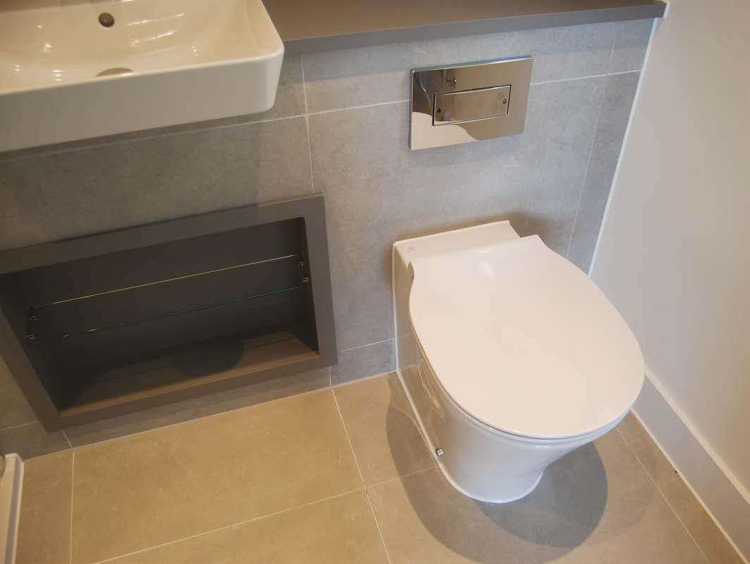
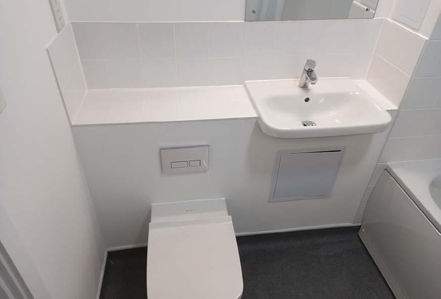
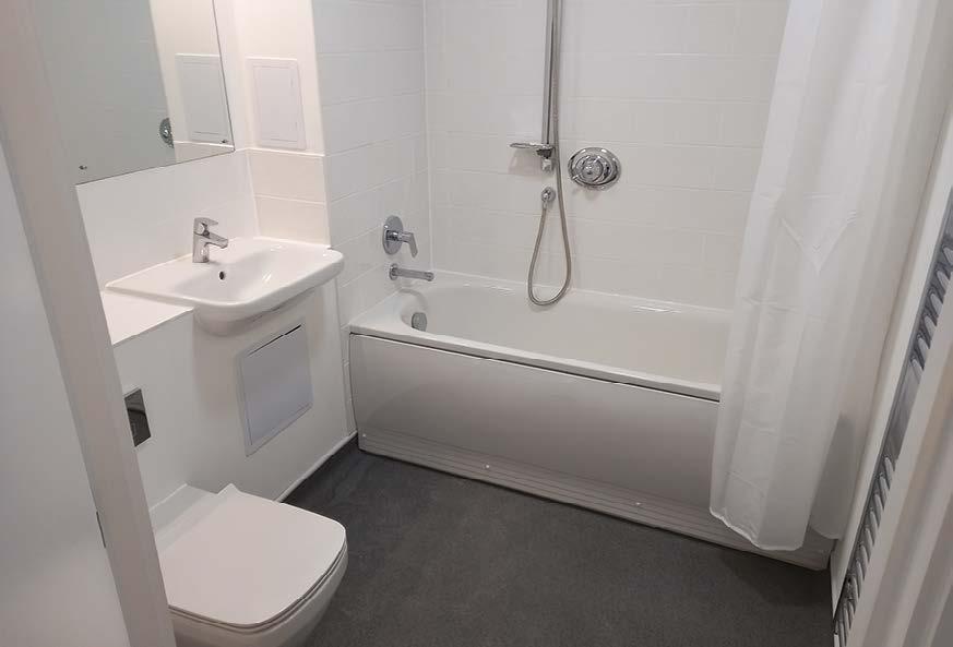
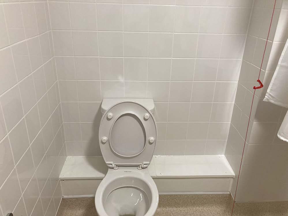
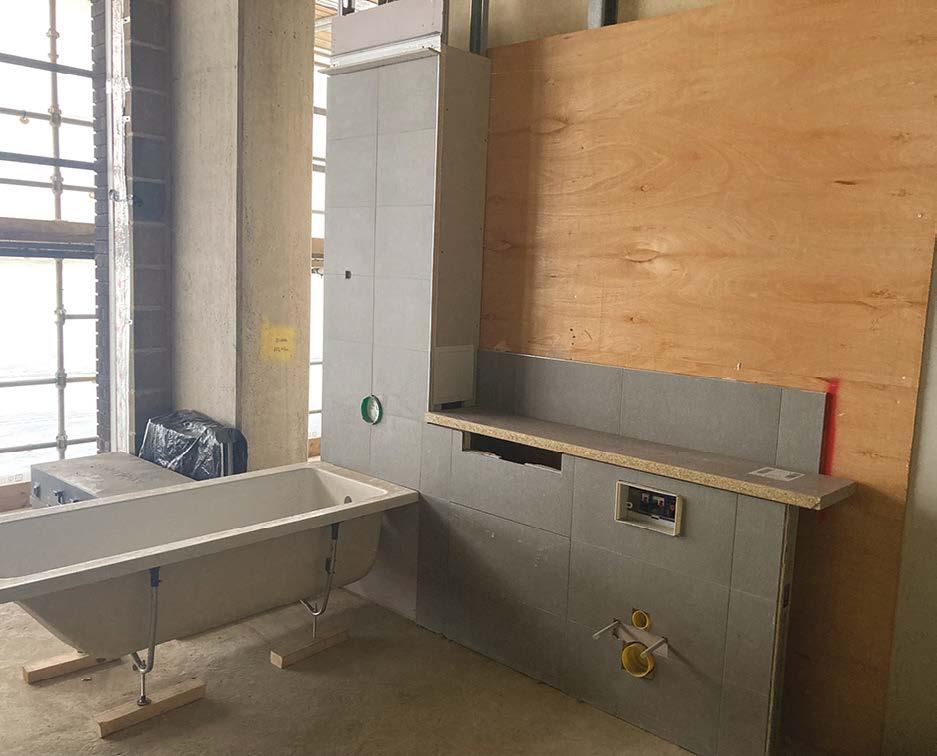
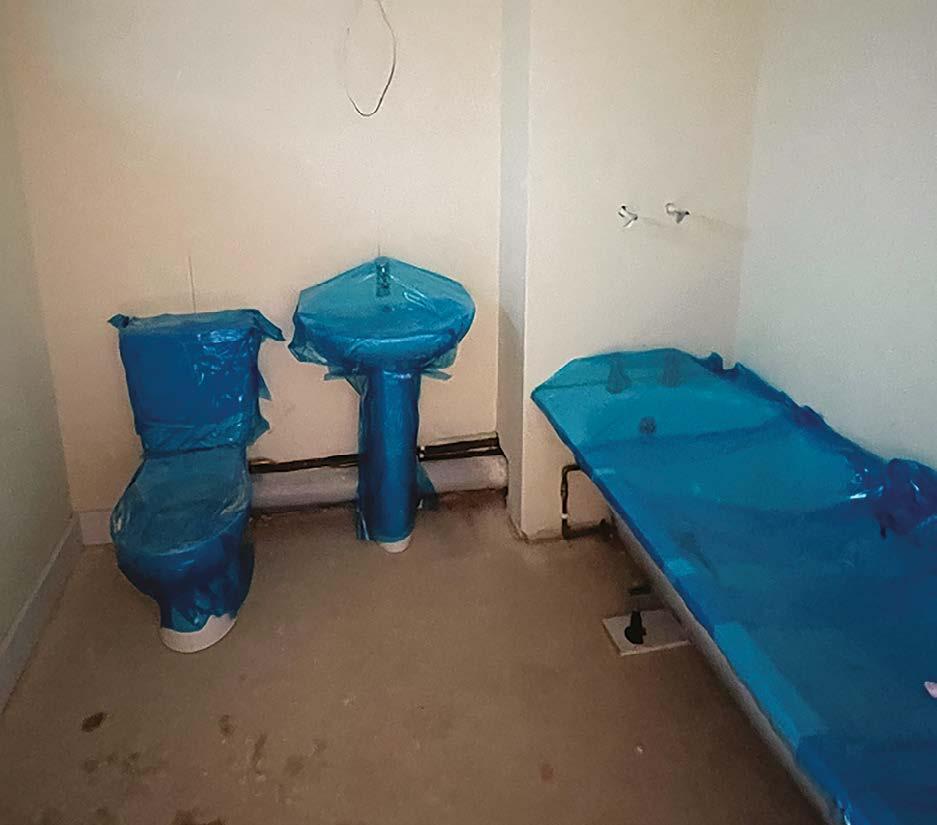
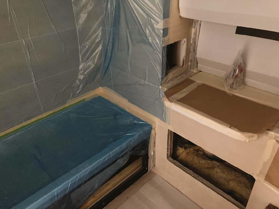
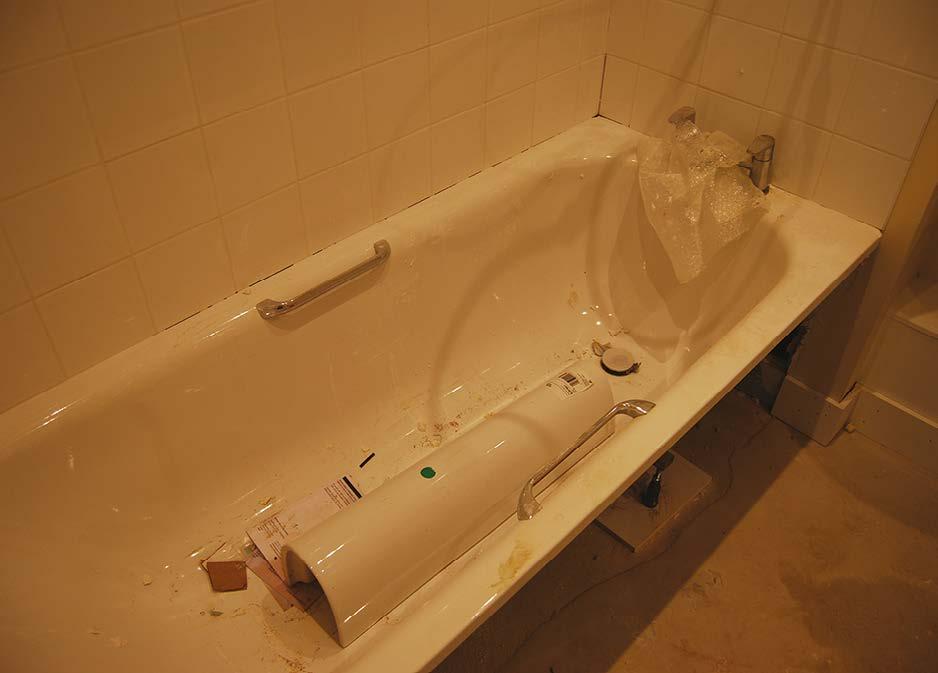
Neat bathroom 1st fix installations, with pipework supported and capped off.
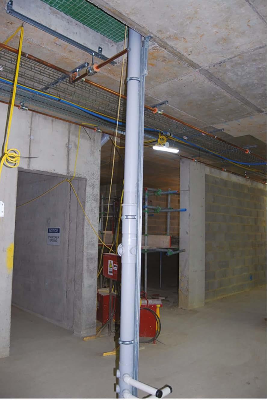
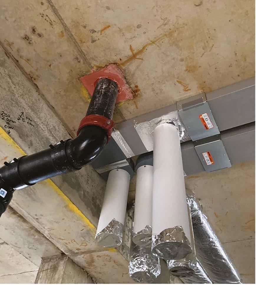
SVP installation
A good example of well supported SVP using an independent Unistrut support system. Also note that the waste pipe connections are temporarily sealed to prevent contamination of the system.
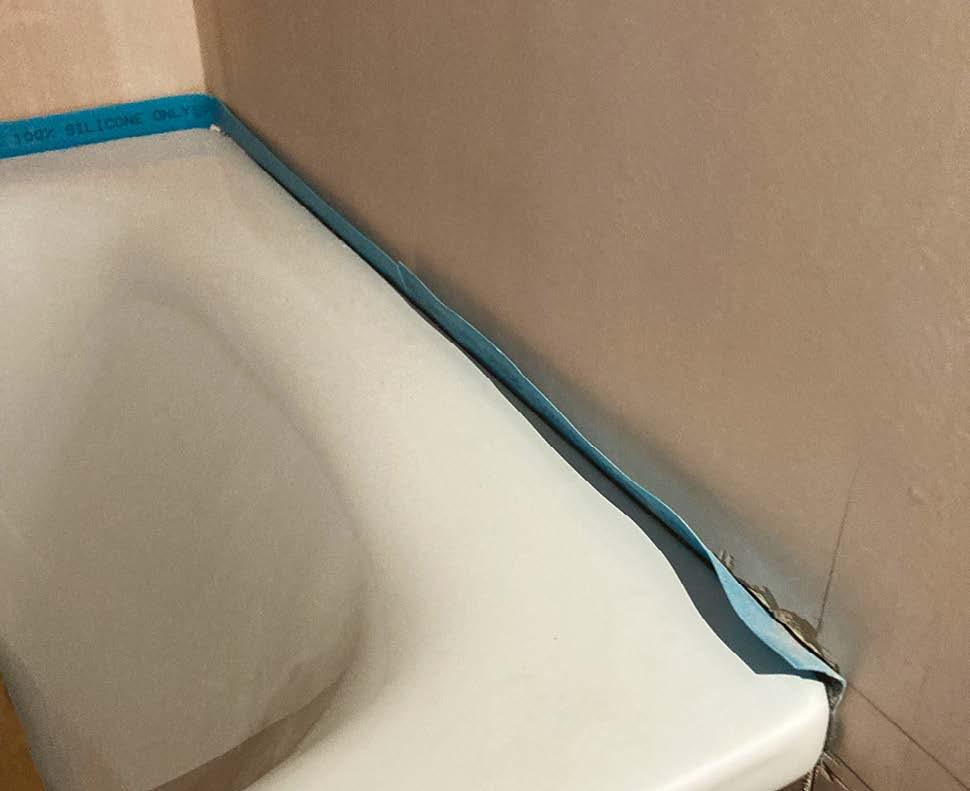
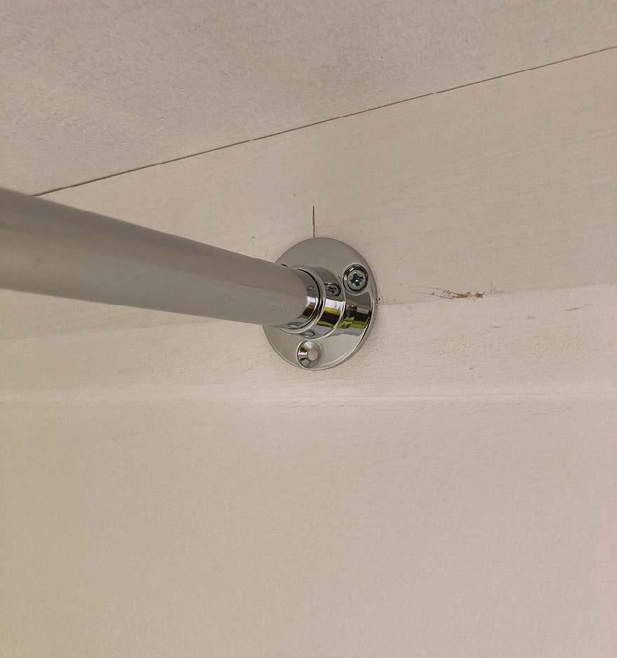
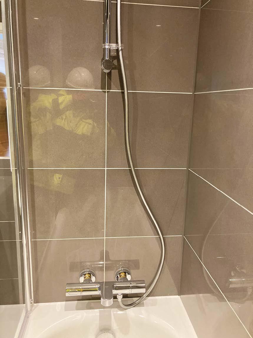
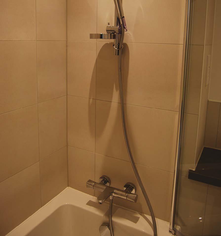
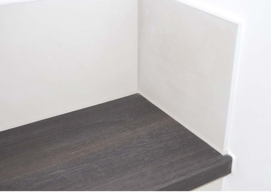
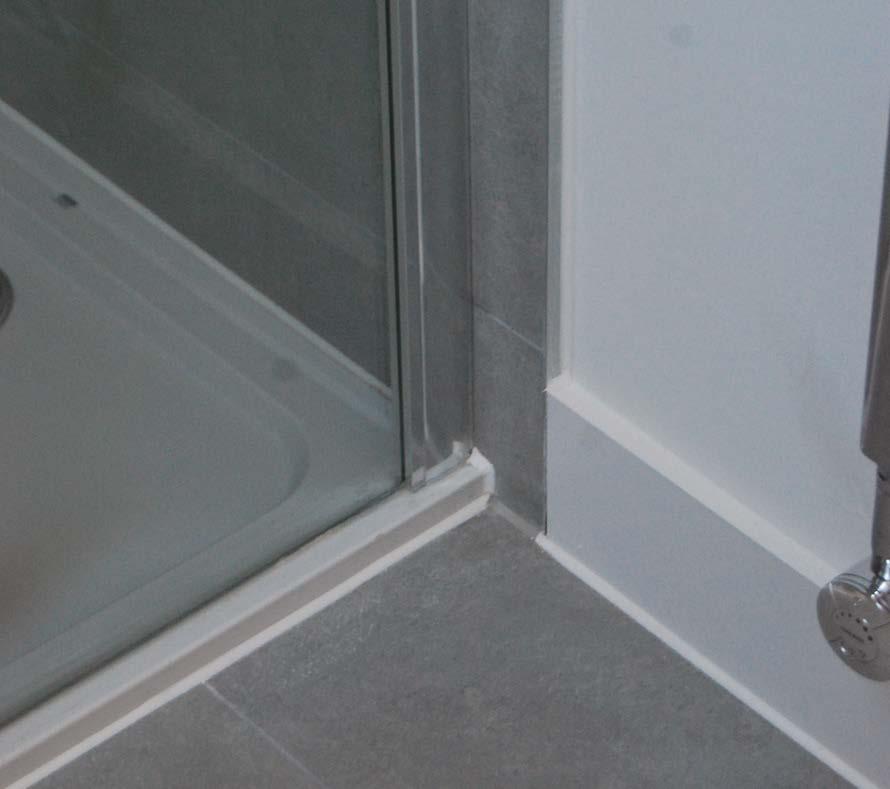
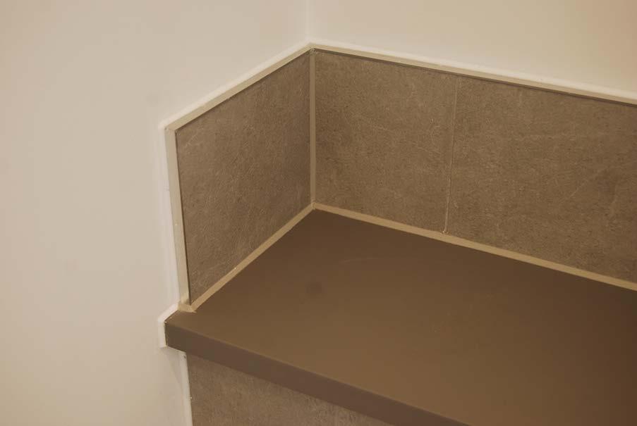
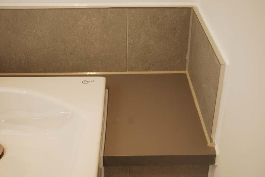
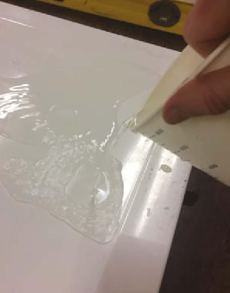
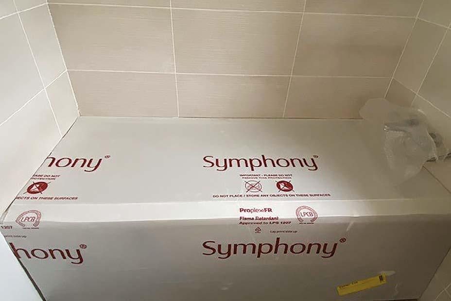
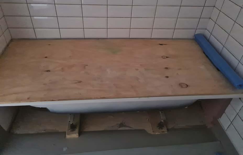
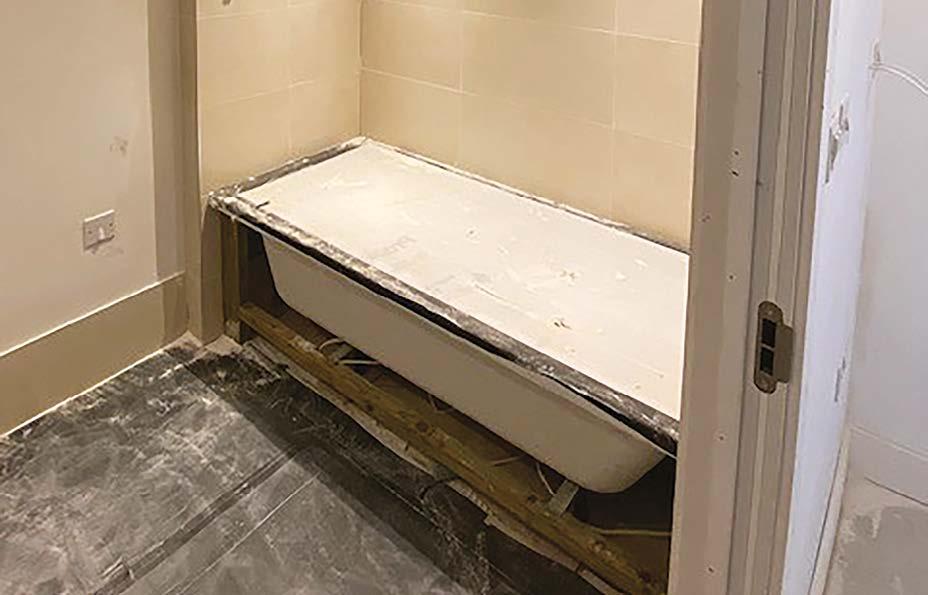
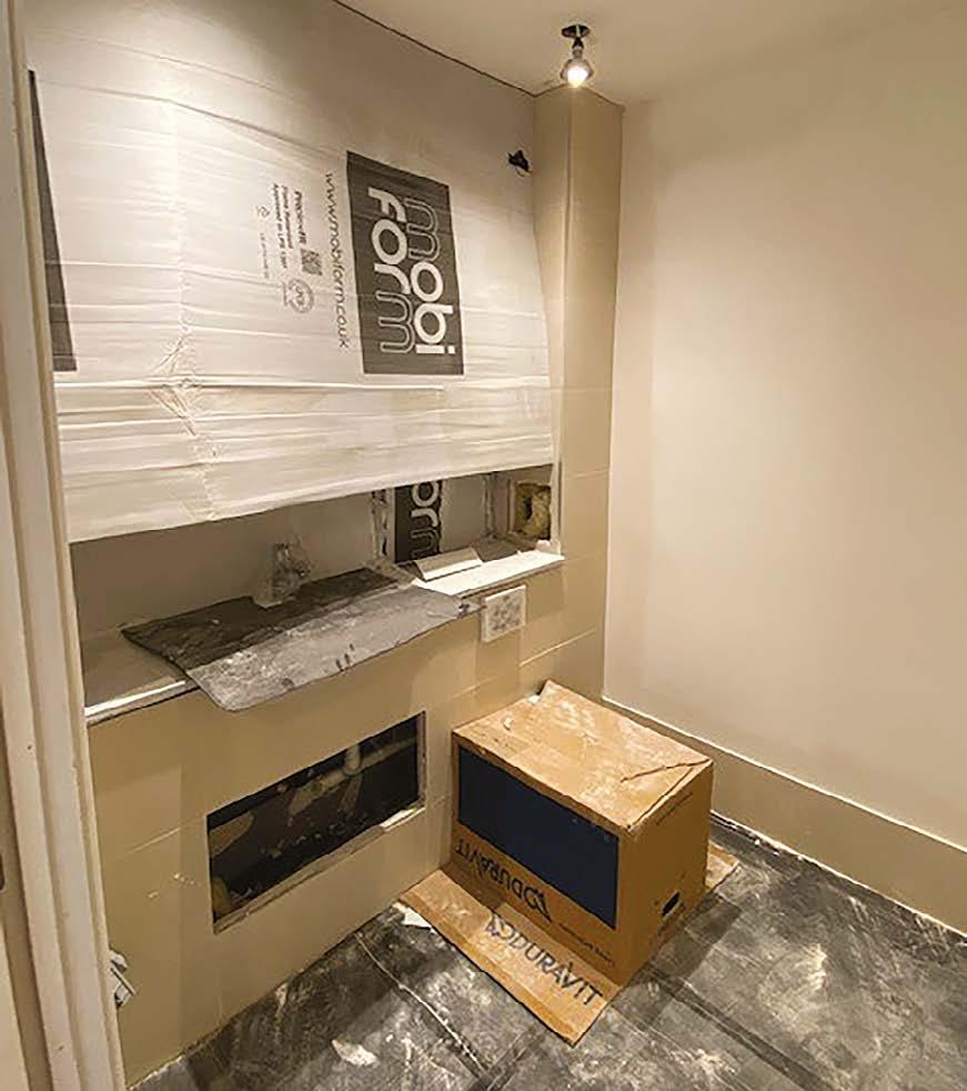
The junction between the tiled wall and the shower tray or bath is the most vulnerable location for water leaks to occur. Proprietary sealing tape should always be applied at this junction and subsequently tiled over. This is then finished by a neat silicone mastic joint.
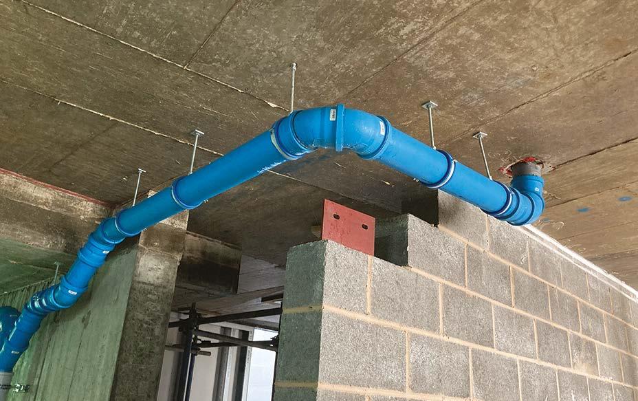
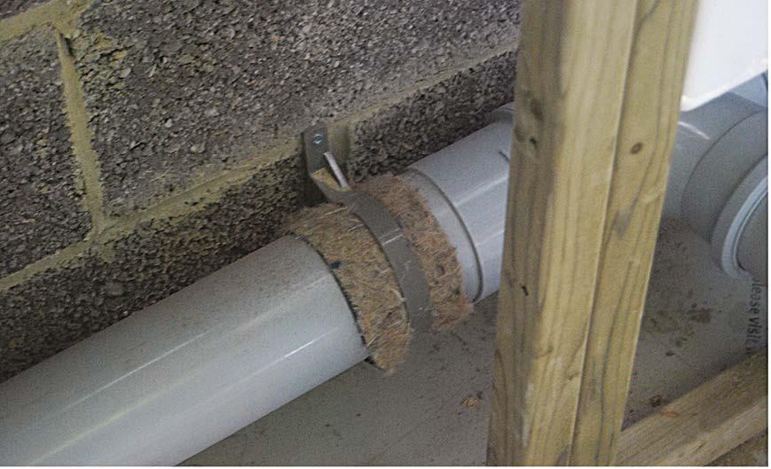
In accordance with Hill’s technical policy, Marley dBlue acoustic drainage has been used along with rubber line acoustic supports where an offset occurs to reduce the potential for noise complaints.
Here a fibre insulation has been wrapped around the drainage at the clip location. This enhances the acoustic absorption and also permits expansion and contraction of the pipe.
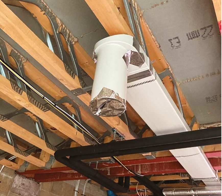
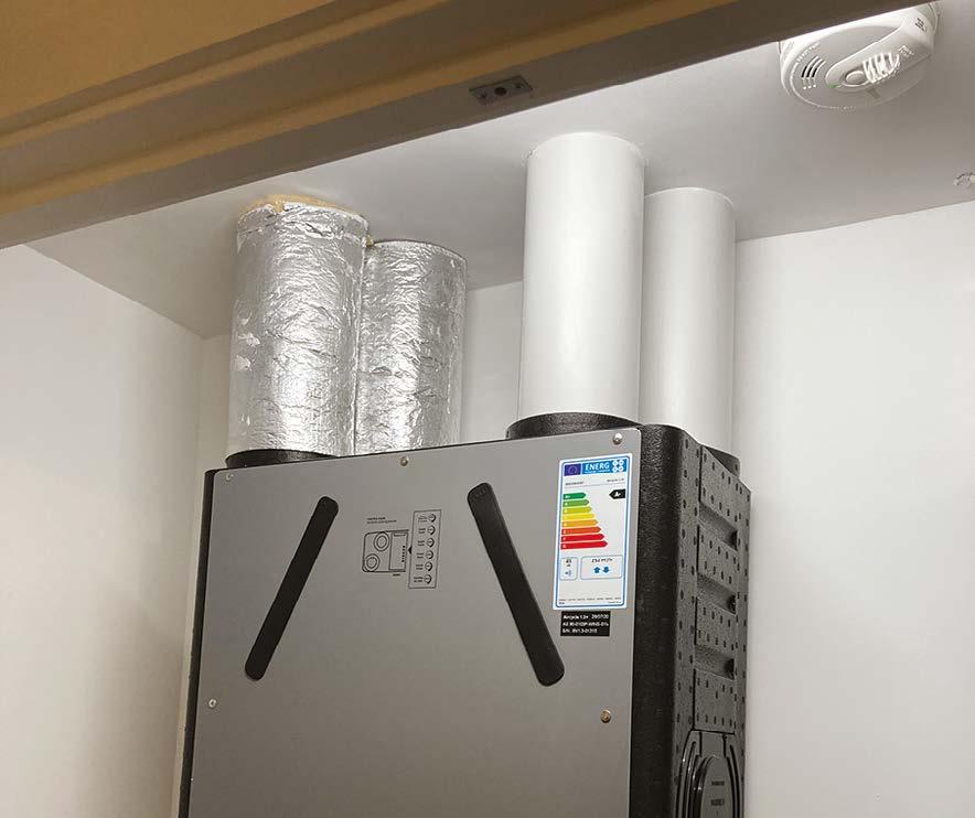
Ventilation
Key issues to look out for:
y Ensure that ductwork is securely supported no greater than every 750mm. (Unless manufacturers instructions differ).
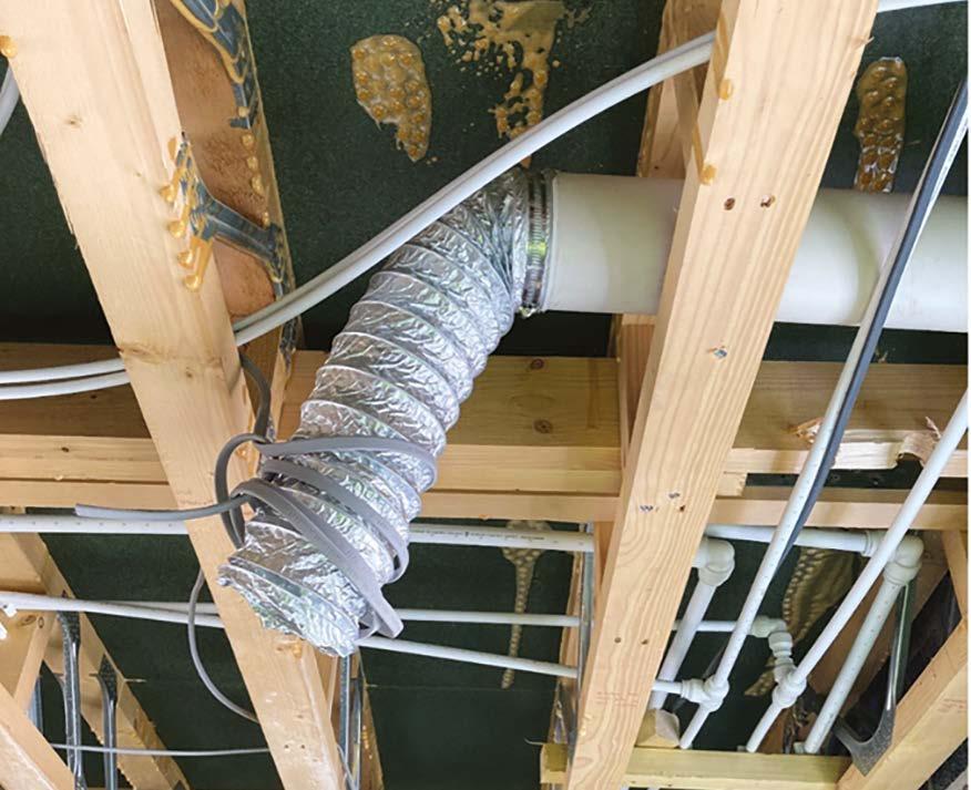
y Flexible ductwork is limited to 300mm straight lengths.
y Flexible ductwork is robust and not tumble dryer hose.
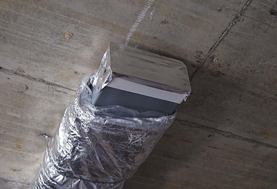
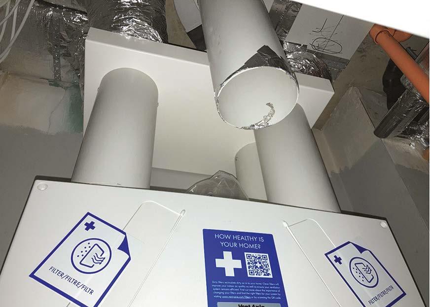
y Open ends of ductwork are temporarily sealed to prevent dust contamination of the system.
y Ventilation installation is carried out by a registered competent contractor (Competent Persons Scheme). Refer to Hill technical policy BQ034
y Intake supply ductwork is insulated within warm spaces and extract systems are insulated within cold spaces.
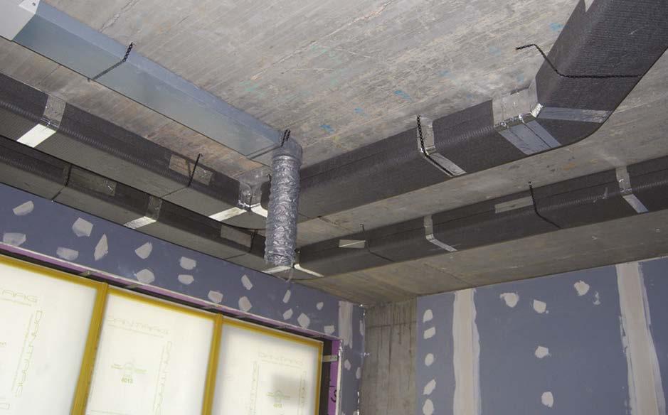
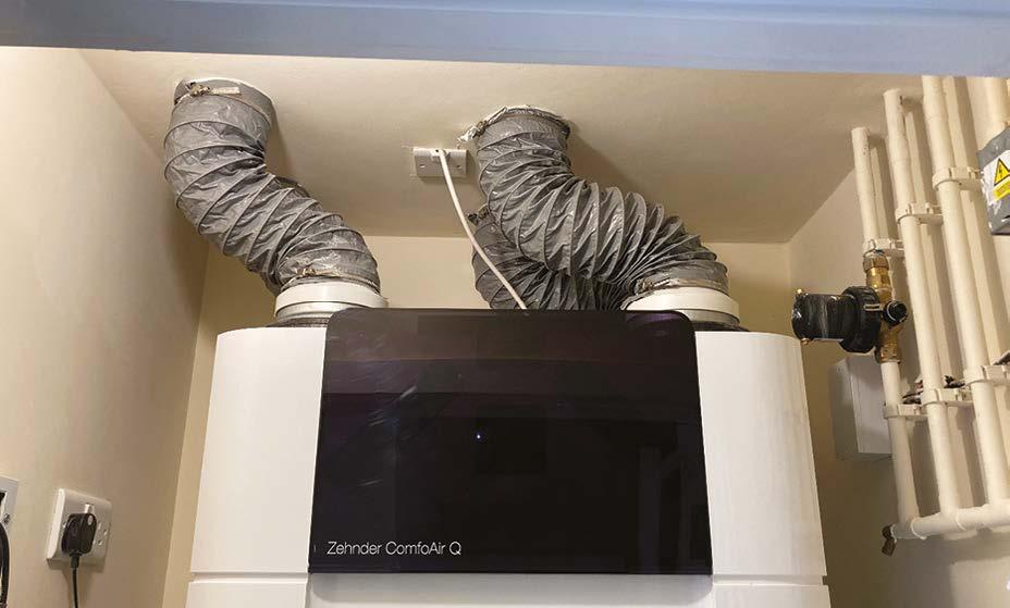
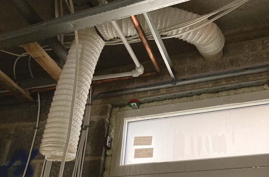
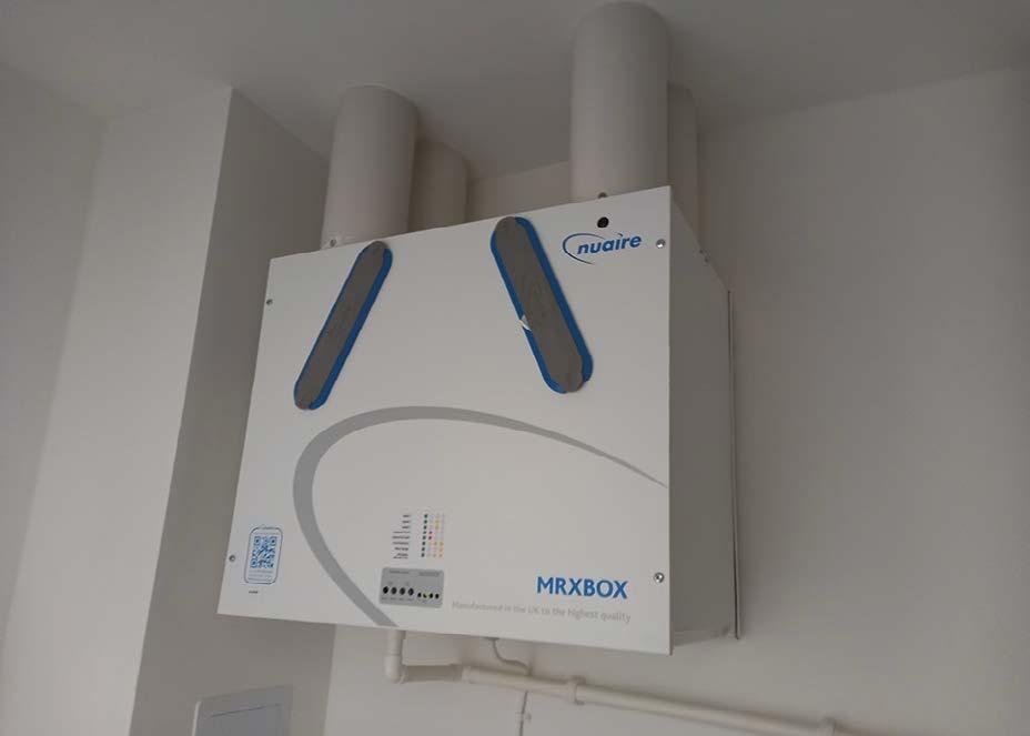
Here we see well-supported ductwork using rigid sections, bends and transitions. Flexible ducting is only used for the final straight connection.
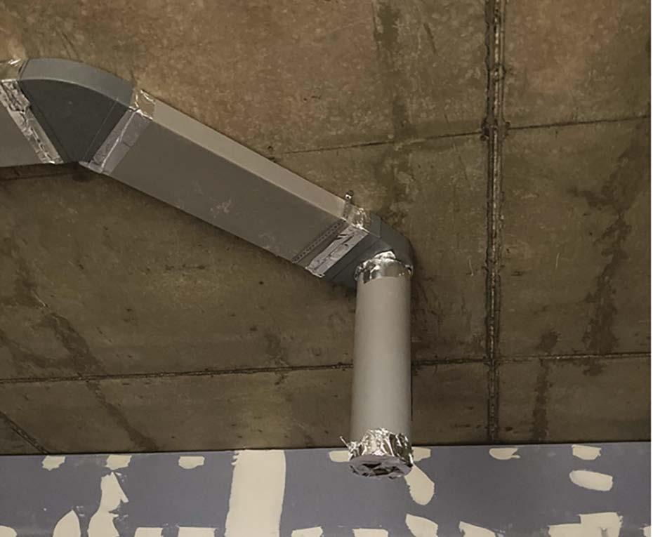
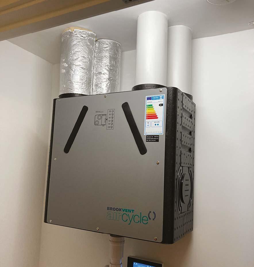
An example of good use of rigid transition pieces and ductwork, limiting the use of flexible ducting to short straight lengths. In this image, the duct should also be temporarily bagged or sealed with tape.
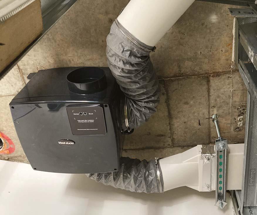
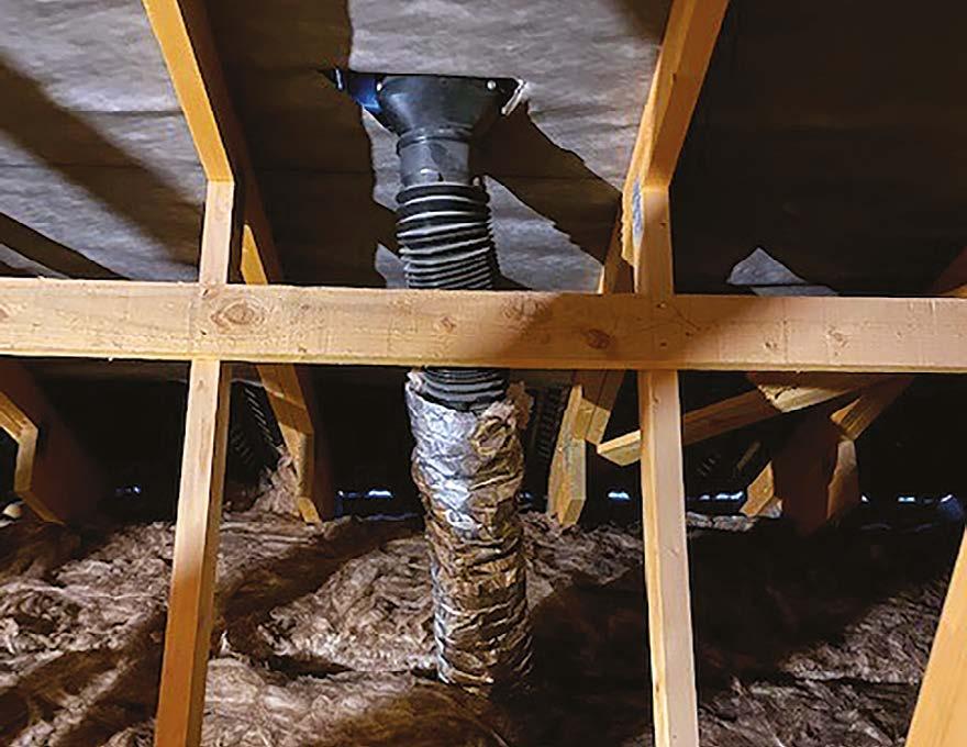
In this poor example, the flexible ductwork is not limited to straight lengths and restricts the airflow. This is not acceptable.
11. First fix (carpentry, M&E services, drylining, fire stopping and windows)
A good example of temporary sealing of ductwork to prevent dust contamination.
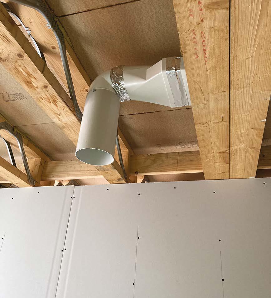
Good use of pre-formed ventilation ceiling panel with duct drops. Creating a very neat ceiling interface and duct drop finish.
Good example of well-coordinated duct installation, presenting a neat and wellpresented finished product.
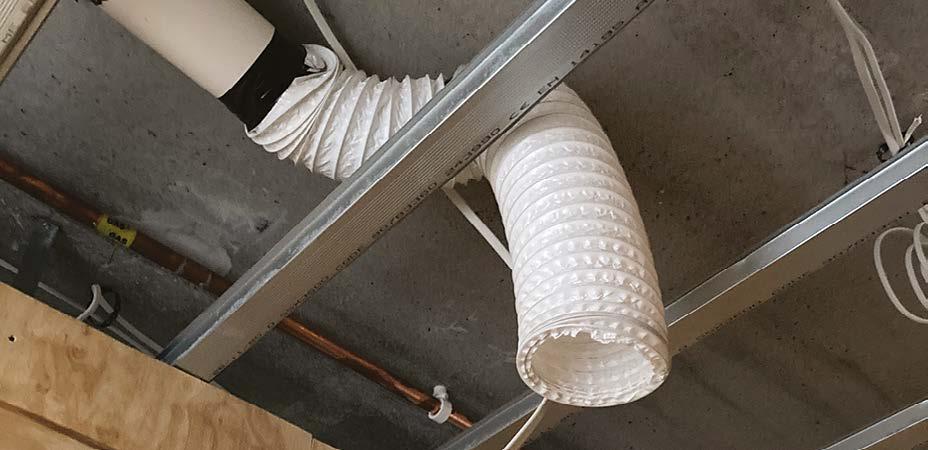
In these examples, this very poor installation has resulted from a lack of planning and coordination between the first and second fix operations, resulting in highly restricted air flow and performance of the system. This will increase fan wear and noise.
Here are some examples of unacceptable use of lightweight tumble dryer type hoses that are over length and not straight.
timber framing line the enclosure and wrap the pipe with 25mm unfaced mineral wool (min. density of 10kg/m3)
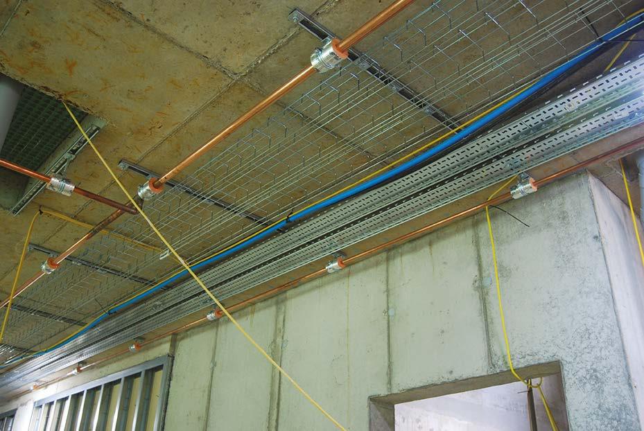
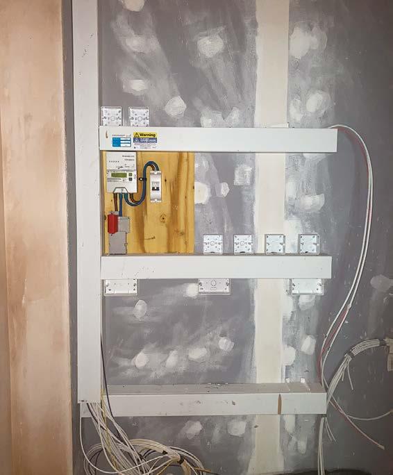
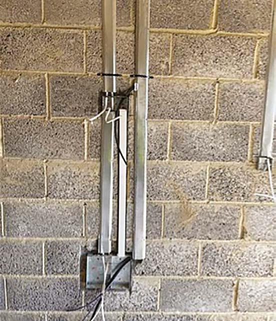
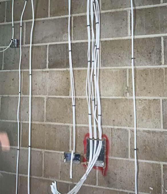
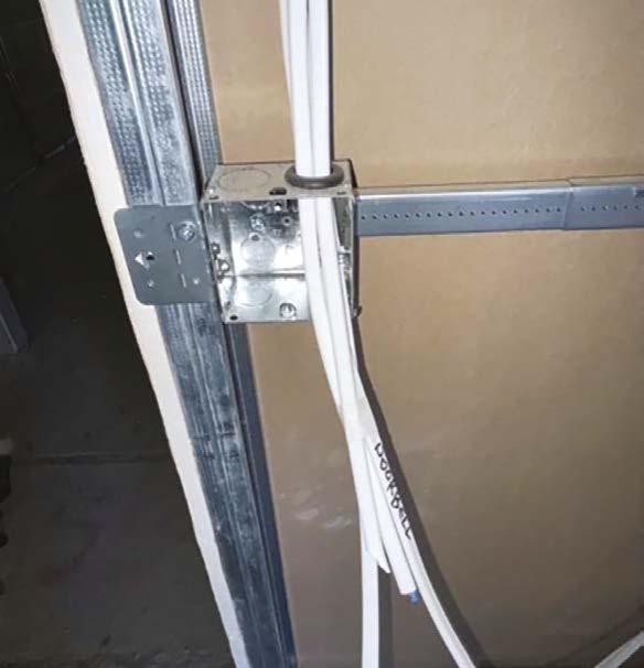
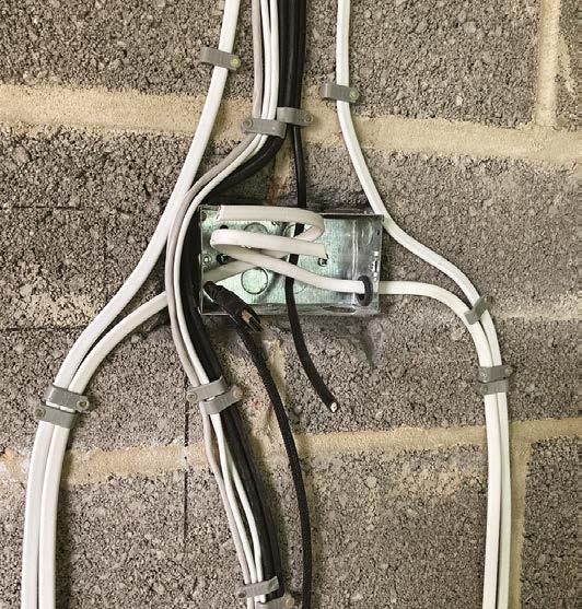
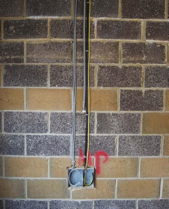
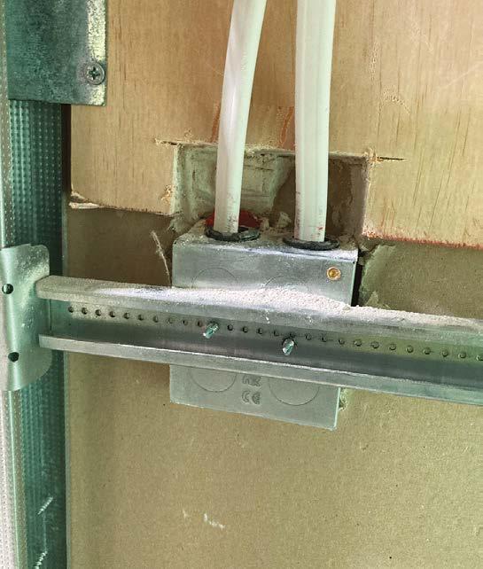
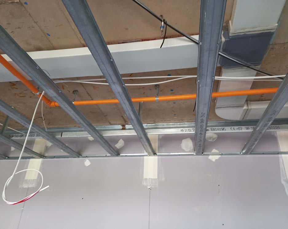
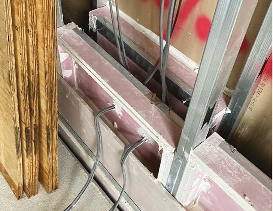
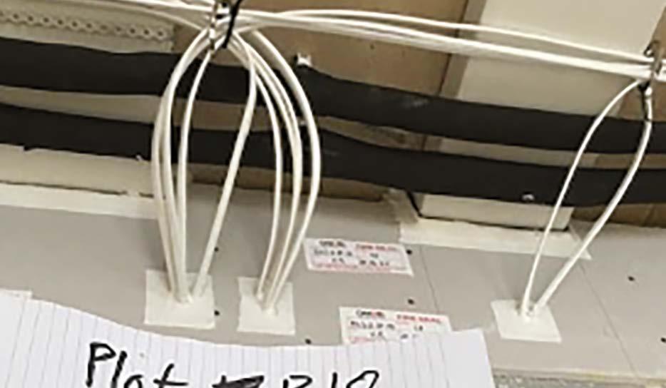
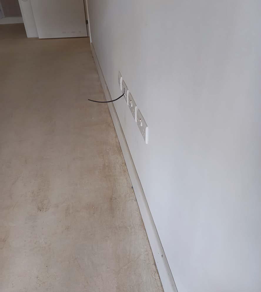
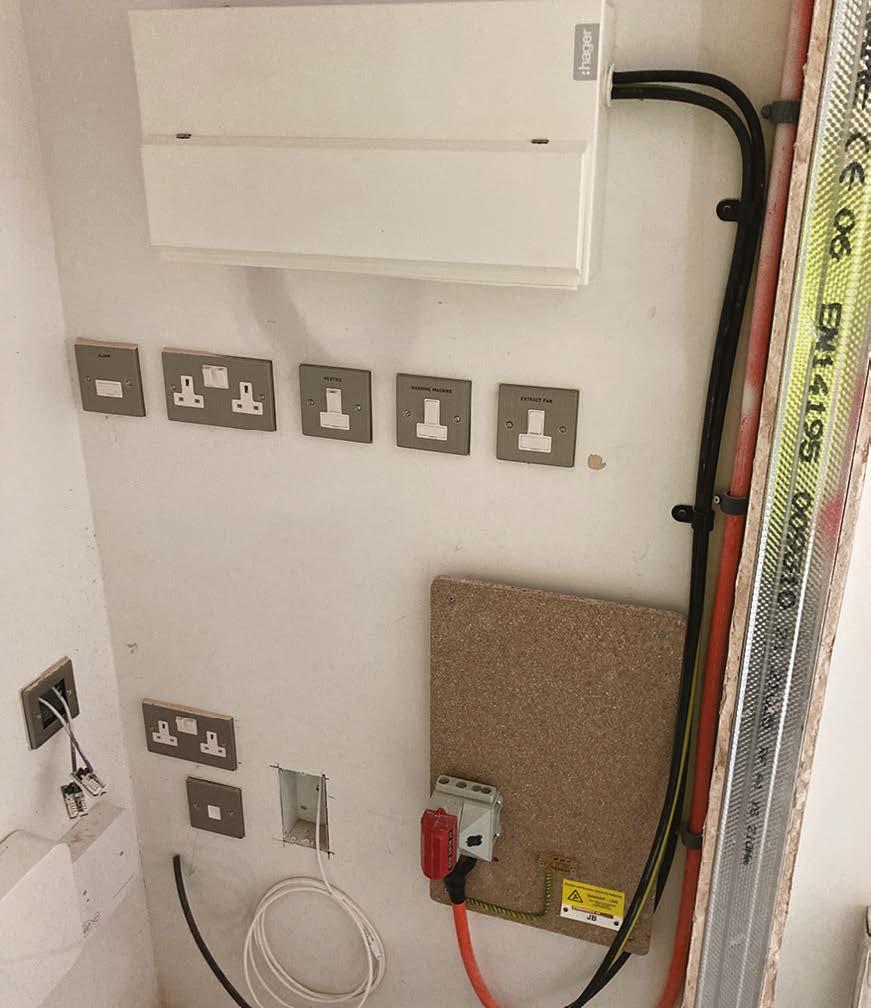
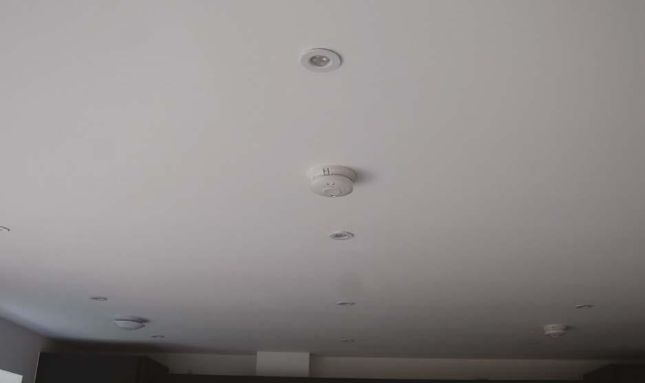
Electrical first-fix installations must be neat and adequately supported. High-level cabling must be clipped with metal clips to all areas where unsupported, in metal trays or within joists, to prevent them collapsing in the event of a fire.
the material of the enclosure should have a mass of 15kg/m2
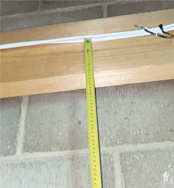
To prevent accidental damage or electrocution during occupation, cables must be fixed in safe zones or physically protected where they are within 50mm of the wall face or 50mm from the top or bottom of ceiling / floor joists.
Where the cable cannot easily be located though use of an outlet (e.g. an external wall light with the cable running internally), physical protection should be applied.
Consumer units should be located so that they are between 1350mm –1450mm above FFL when measured to the centre of the miniature circuit breakers MCBs.
In the case of duplex consumer units, the lower MCBs must be located between 1350mm – 1450mm above finished floor level as shown opposite.
Consumer units should also be positioned no less than 300mm from an internal corner, when measured to the centre line of the MCBs.
Diagram 1 -
the material of the enclosure should have a mass of
Residential buildings >18m or including student accommodation or care facilities must include arc fault detection devices (AFDDs) installed on all power circuits.
Sockets, switches and controls must be located between 450mm and 1200mm when measured from the floor and no less than 300mm from an internal corner.
Sockets should not be located within 300mm of wash basins or sinks as shown in Diagram 1 and 2.
Sockets should not be located within 100mm of a cooking hob as shown in Diagram 3.
Diagram 2
Diagram
Diagram
11. First fix (carpentry, M&E services, drylining, fire stopping and windows)
A neat electrical installation within a utility cupboard using trunking.
Good use of metal protective capping to cables where they are outside the safe zone.
Here the cables have been fixed to a ceiling joist at least 50mm from the bottom of the joist.
A neat installation with cables all run vertically within the safe zones created by the outlets.
A neat and tidy installation within a metal stud partition. All sockets level and in alignment with rubber gromets installed to all knock outs.
An example of unacceptable and potentially unsafe works, with cables installed outside the recognised safe zone (horizontally and vertically established by the outlet).
Neat cabling installed within the safe zone created by this large media outlet.
A suitable plywood has been installed here to provide a solid fixing for a pendant light.
In these poor examples, the electrician has compromised the fire integrity of the wall by damaging the wall board.
Air Source Heat Pumps (ASHPs)
ASHPs are relatively new domestic heating and hotwater energy systems and as with all things new, an understanding and appreciation of low temperature ASHP systems will be necessary to have an long lasting, efficient and productive system.
Because ASHP’s work to deliver hot water at a much lower temperatures than gas boilers (45/50°C degrees or lower compared to 70°C for a gas boiler) we need to protect the heat that is produced by the heat pump and eliminate as many losses as possible so that this heat is then usable.
Key issues that affect the performance of an ASHP system are:
Design:- the designer of the system must accurately determine the heat losses from the home and size the ASHP, water storage cylinder and heat emitters (radiators or underfloor) correctly as both under and over sizing of any elements of the system will impact on performance and efficiency. Heat emitters should be designed such that the flow and return temperatures are 45°C and 40°C respectively.
Accredited designer & installer:- the system designer and installer should be accredited through a recognised agency, such as the Microgeneration Certification Scheme (MCS).
Installation of the ASHP: This should be installed on a robust foundation with provision for condensate drainage, anti-vibration mounts and the unit MUST be installed level to prevent premature wear to fan bearings. The Hill standard detail should be followed.
Exclusion Zones:- Manufacturer’s instructions must be followed in relation to specified ‘exclusion zones’ around the ASHP. This will restrict the location of valves and walls / screens that may affect air flow across the unit to ensure that cold air is dispersed, preventing the creation of a localised cold micro-climate, that will effect performance of the system.
Pipe insulation:- Any un-insulated or inadequately insulated pipes, valves or fittings, whether through gaps, splits not being sealed or incorrect thickness will result in poor heating of the property, extremely high electricity bills and an unacceptable customer experience.
Condense pipes:- These should be short runs, installed in accordance with manufacturer’s instructions to prevent freezing in cold weather.
Flushing and bleeding:- it is important that the system is fully flushed and deaerated using a filling station (pump set). Glycol, added to the primary system as an inhibiter / anti-freeze, reacts with air to produce a brown sludge. It is therefore vital that all air is removed from the system.
Heating controls:- Due to the low temperature of these systems, the ability to heat a cylinder of cold water, or a cold space will be very much extended compared to a gas boiler system. It should therefore be commissioned to operate at a steady constant temperature rather than ‘off and on’.
11.
First fix (carpentry, M&E services, drylining, fire stopping and windows)
Internal Drylined Walls
System
Many internal walls within houses and most of the walls within RC framed apartments are constructed from plasterboard drywall systems.
These must be constructed to a high standard to ensure that the finished walls are straight, plumb, square to corners and finished ready to receive the direct application of paint. They should also be constructed to resist the potential for future movement or cracking.
In addition, these walls often perform one of more other critical functions, including;
y Forming a fire resisting compartment wall/ structural fire protection.
y Creating a thermal barrier between warm and cold spaces/elements.
y Providing acoustic insulation to sound sensitive environments.
Drylining must always be constructed as a ‘system’ and not a ‘pick and mix’ assortment of materials.
Failure to construct drylined walls correctly may compromise performance of the wall and reference should always be made to the detailing and construction requirements stipulated by the system provider.
Boarding
Walls (and ceiling) boards may be specified to meet any of the following performance requirements: sound, moisture and fire. It is good practice not to mix board types within a given wall unless detailed to be so constructed.
Where multiple layers of boards are required, particularly where installed for fire performance, it is important that each layer is fully fixed independently of preceding or subsequent layers. A double boarded fire compartment wall relies of each board layer to face the fire in turn and remain in place for the tested period.
Plasterboard screwed to studs must be screwed at a maximum 300mm centres and 200mm to external corners. Screws must be slightly recessed but the flange of the screw should not break the paper face of the board.
Importance of screw depth into plasterboard
Bad – screw is too deep and had gone beyond the paper face.
Good – screw just recessed into board with the paper face unbroken.
The screws fixing the multiple layers of board at the correct centres can clearly be seen from the reverse side
Boards may be finished with wet plaster or taped and jointed. Both systems have advantages and disadvantages and should both be finished to a comparable standard to walls. On ceilings, taping and jointing may cause small humps at the board short edge, butt joint locations, which may be visible when light shines across the ceiling.
Board joints and screws must be taped and filled with jointing compound/plaster to achieve the specified fire and acoustic performance, even where these are above ceilings.
Dot and dab linings
A common method of finishing concrete or masonry walls is to bond plasterboard to the face using adhesive dabs.
Where the ‘dot and dab’ method of bonding plasterboard is adopted, it is important that these are correctly applied as noted below:
Indiviual dabs to be approx. 250mm long by 50mm wide at 300mm centres
Dabs per 1200mm wide board
Board thickness Dabs
9mm
Four vertical rows of dabs
12.5mm Three vertical rows of dabs
15mm Three vertical rows of dabs
See table below for number of vertical dabs required
It is important that the building is weather tight and the substrate masonry is reasonably dry and free from damp (<16% moisture content) prior to progressing the dot and dab boarding. If this is not achieved, there is an increased risk of black mould damaging the boards.
11. First fix (carpentry, M&E services, drylining, fire stopping and windows)
Partition deflection head detail completed, with all joints taped and jointed above the ceiling level before the ceiling framing installation, to provide a full smoke seal to the partition.
The head track on this three-sided letterbox service opening is correctly formed with a short return across the twin wall studs.
All boards are sealed to the concrete slab and tightly butted together.
Here the head track is assembled to the core board deflection detail on the ground and mastic fire sealant applied before being fixed to the soffit.
In this example, the short infill return has been missed to a three-side letterbox. This detail is incorrectly formed and provides an inadequate fire seal to the reveal boards within the letterbox.
Plasterboard is cut to avoid joints along the lines of door jambs as these are liable to crack. Boards are fixed at a max 300mm centres (200mm to external corners).
Twin wall party walls are taken to the structure and screeded. Thought has been given to providing a lap to the two layers of board with a metal fixing strip inserted to maintain the fire and acoustic wall properties. Acoustic foam is also installed between the screed and structural floor, columns and partition.
Here, we see partition walls located ahead of the underfloor-heating pipework installation, enabling pipework to run through doorways and avoid potential penetration through drilling.
11. First fix (carpentry, M&E services, drylining, fire stopping and windows)
Fire Stopping
The Hill policy is that all holes and service penetrations must be fire stopped regardless of size and this must be carried out by a specialist fire stopping contractor (unless cast into concrete framed buildings). This policy is significantly higher than minimum regulatory standards.
Service installations and particularly ‘letter box’ penetrations should be well coordinated to ensure the insulated pipes remain within prescribed distances apart from each other and also from the perimeter of the opening.
Use of a letter box service entry template ensures consistency and compliance.
In this image, plasterboard baffle boxes have been used to provide enhanced sound insulation between two dwellings, due to the sockets being back-to-back across a party wall, which is bad practise and should be avoided.
Here are some good examples of fire stopping of a three-sided letter box where services have been located no closer then 50mm from any perimeter or between services and pipe insulation has correctly been extended continuously through the wall. A QA sticker is also clearly visible from the installing specialist fire stopper.
Graphite sealant has been used to plastic sprinkler pipes.
Raising the bar even further with long-stem valves also used in this installation to ensure that the thermal insulation is not discontinued at valve locations in order to operate the lever.
Here a duct has an intumescent fire sleeve installed where it passes through a compartment wall.
Cast in intumescent seals should be provided on reinforced, concrete-framed projects.
An intumescent wrap and compound have been installed to this SVP penetration as an alternative to a cast in sleeve.
In this example, the fire stopping has been correctly completed, however, the pipe insulation should have been run continuously through the fire batt and fire-sealed to the insulation with a suitable, tested material.
11.
This is a neat job and is being referenced for a QA digital record. The large square holes around the cables indicate, however, that the plasterboard was cut oversized or damaged, as a 10mm bead of fire sealant is all that is typically required around cable penetrations, including multiple cable bundles. This is a costly detail to overcome poor workmanship when cutting the service holes.
Here we see a good example of two service penetrations through a masonry compartment wall where surface-mounted intumescent collars have been installed with fixing lugs all correctly fixed.
In this example, a surface-mounted collar has been installed around a plastic SVP penetrating a PCC floor plank. All fixing lugs are securely fixed.
Another good intumescent wrap installed around a plastic ventilation duct through a drywall partition.
On the face of it, this looks like a good job, but it is not acceptable as the conduit sleeve is plastic and will simply melt away, negating the fire seal at the end of the conduit. The structural hole is also oversized requiring excessive fire sealant. The anulus should be circa 10mm.
Where plastic conduits are used, these must be finished flush with the plasterboard wall face so that a good fire seal is provided.
Windows
Windows should be fixed on all four sides at a maximin 600mm centre, horizontally or vertically, and be between 150mm and 250mm from an external corner. (Unless otherwise specified by the window manufacturers.)
There should be a minimum of two fixings on each jamb and sill, and they should be a minimum of 150 mm from the centre line of a mullion or transom.
The above is general guidance as the number and spacing of fixings depends upon the frame width and frame material. The manufacturer’s instructions should be followed.
Where fixing straps are used, these should slope slightly downwards (inside to outside) as in the image below, to avoid the potential for water ingress.
In this image good practice has been adopted and the cavity closer has been sealed with mastic to enhance the airtightness of the home.
Door cills should be solidly supported to resist deflection when stood on.
In this image, care has been taken to ensure that the underside of the ground floor French doors have been mastic sealed.
11. First fix (carpentry, M&E services, drylining, fire stopping and windows)
This is very good practice, as a folded upstand has been formed within the cill to provide a stop end and also a solid face to mastic the joint between the wall and cill.
This photograph demonstrates how vulnerable wide cills are to water ingress where they rely solely on a mastic joint. It is unreasonable to expect mastic to bond to a cill in this way and to withstand the expansion and contraction that this cill will experience. An upstand should be produced with a catchment cavity tray installed below.
Pre-plaster hold point inspection
A neat window installation with protection applied to the stone cill and window extrusions.
An example of neat installation and mastic work.
The Hill Group QA procedures requires all homes to receive a pre-plaster inspection prior to closing up works. This inspection is to be carried out when masonry walls, windows, first side plasterboarding, services first fix, carpentry first fix and all fire stopping is complete. The aim of this is to hold the closing up of walls and ceilings along with all subsequent build operations until this stage is signed off, defect-free. It is therefore a ‘hold point’ as works should not progress beyond this point until signed off.
12. Second fix (carpentry, kitchens and M&E)
We are now at a stage where finished quality internal works are being installed. This is when many homeowners and visitors will judge the quality of the builder.
Attention to detail will make all the difference at this time.
Second fix carpentry
It is important that second fix carpentry elements are completed with care, attention to detail and without reliance on subsequent decoration trades to overcome a poor level of finish.
Neat, consistent door margins.
In this image, we can see good on-site quality control with a 2mm fire door margin to the frame being checked by a gap width gauge and recorded on the digital QA platform.
Excellent examples of the neat cutting and finishing of door furniture.
12. Second fix (carpentry, kitchens and M&E)
In these examples, stair string and landing skirtings have been installed to an apartment staircase. The carpenter has 'expressed' the joint between components by introducing a ‘vee’ joint. This chamfer has also been created to the exposed top of the MDF (and where visible on stair strings, the bottom of the MDF). This attention to detail creates a robust solution that is easier to finish to a high standard and conceals inevitable cracking that will occur between each element.
The ‘vee’ joint between the string and landing skirting is also a good way to abut materials of different thickness, as seen here.
The wall and skirting are nice and straight.
In these images, the carpenter has overcome a co-ordination issue between the skirting and the window jamb by neatly returning the moulding down to the end of the skirting.
Neat cutting of skirting mitres; the wall and skirting have both been finished square.
In this example, the carpenter has partially mitred the architrave and skirting to maintain the groove across the architrave and skirting – showing great workmanship and attention to detail.
Here we see a good quality architrave installation, with an even 5-10mm margin between the frame and architrave. The image also shows tight fitting, accurately cut mitred joints.
In this example, the hanging rail height is set by the depth of the intermediate support bracket and the use of standard skirting is not deep enough. Care should have been taken to install an alternative deeper shelf support.
In this example, the window board is not deep enough to adequately project in front of the wall face.
12. Second fix (carpentry, kitchens and M&E)
Here we have neatly finished hardwood boards masking the bracketry under windows. A maximum of 15mm step is permitted if an accessible threshold is required.
A neat finish to this newel and half newel detail. A neatly constructed fitted wardrobe.
Kitchens
They say that the kitchen is the heart of the home. It is important that we create a strong heart for our homes, with care taken in not just the cabinetry but also the M&E systems that integrate with this.
In these images we can see that the plumber has taken care and pride in their installation, with pipework neatly installed and clipped. Decorative cover collars have been provided to pipe penetrations, including the waste pipe.
The waste system and traps are very neatly installed to provide the least intrusion possible within the cupboard space.
Through thoughtful plumbing, the carpenter/ kitchen fitter has also taken great care to neatly cut and install the middle shelf, providing valuable additional storage space to the occupier.
Holes have been neatly drilled to enable the pipework to enter the cupboard.
12. Second fix (carpentry, kitchens and M&E)
In these images, it is impressive that the plumber has really thought about where to run the hot, cold and waste pipes. The installation is in progress, but note how the vertical waste is right to the back of the unit, how neatly the holes have been formed in the back of the unit and how well installed the hot and cold pipework is.
Here the carpenter has done a neat job in cutting out the shelf to accommodate pipework and waste pipes. The plumber could have potentially improved their installation and taken the waste to the back of the unit, avoiding such deep cut outs.
These images clearly show the work of someone who takes pride in what they do.
In these examples, the shelf has been severely weakened as a result of poor setting out and lack of care; the incoming water main is located completely inappropriately at the front of the unit.
In these kitchens, no attempt was made to cut and re-install the shelf to the sink base unit, depriving the occupier of valuable storage space. Leaving the shelf brackets in place only adds insult to injury – it might as well say “look what you could have won, if only we cared.”
In this image, the shelf has been weakened to a point where is it likely to break as the plumber has brought the waste fittings forward, rather than to the rear or the side.
Benchmarking is important to set a standard that encourages the plumbers to plan pipe routes in these confined spaces.
An example of how to fill a useful storage cupboard with pipework and waste pipes, including another mains water pipe badly located. All avoidable with care and pride.
12. Second fix (carpentry, kitchens and M&E)
A neat kitchen installation, with all units, door and drawer fronts in alignment with even gap widths.
Neat granite work can be seen here, jointing this splashback.
Island unit extract system installed without a vent. The extractor will not work as it cannot exhaust the air.
Second fix plumbing
When doing second fix plumbing, we are looking for functionality as well as neatness and pride taken by the installing tradesperson.
Starting with works within a cylinder cupboard, we see here a very high quality installation, with insulation carried out to a good standard, with all valves nicely labelled. This looks like someone with skill, care and pride in what they do has been at work.
Note that brassware to the cylinder is fully insulated to prevent heat loss/overheating.
Could it be improved upon? Yes, as the valves remain uninsulated, and electrical insulation tape should not be used. Foam tape or a suitable adhevsive specified by the manufacturer should be used.
12. Second fix (carpentry, kitchens and M&E)
In these examples, insulation pipes are uninsulated where clipped and little effort has been taken to insulate brass fittings to the cylinder and other components. This will be the source of heat loss and energy inefficiency and overheating as well as looking poor.
Does this quality of insulation look to have been carried out by a competent tradesperson who takes pride in their job? We must do better than this.
This is a work in progress but the pipework is neat and the HIU is protected with the pressure relief tundish within 600mm of the appliance.
Very neat, quality work with distribution pipework.
12.
Second fix (carpentry, kitchens and M&E)
In this installation the underfloor heating manifold has been neatly hidden within this boxing and access panel.
The gutter/downpipe fitting has been twice screwed to the fascia board.
Here we see a novel way of providing additional stability to the stop end of gutter, by running the gutter across the downpipe fitting and carefully core drilling a hole in the gutter, providing added support to the end of the gutter.
Pipes neatly run and terminate into the partition wall, finished with white collars.
Downpipes secured to wall and black screw caps fitted to conceal the heads of the screws.
In this example, metal gutters and downpipes were installed very neatly to meet local planning restrictions.
Here we see an unacceptable installation, with elements of the brass valve exposed to the cold air. An insulated valve jacket should be fixed here.
Neat insulation to these air source heat pump installations, with valves and fittings insulated.
A neat dry riser installation.
Good use of insulated valve jackets here.
12. Second fix (carpentry, kitchens and M&E)
Second fix electrical
A neat finish is important to sockets and switches – care and attention is needed to ensure that these are level, aligned to each other and evenly spaced.
Aim for a design gap of no less than 30mm between outlets, to enable a consistent neat wall finish to be achieved.
Here the sockets are unevenly spaced and too close to make a decent job of finishing the wall – unacceptable.
Our standard bathroom details indicate that the spur outlet is to be located to align with the bottom of the towel rail, close to the side where the electrical heater is located. Where this is not possible, it should be located under the towel rail.
Here we see the
In this example, the spur is wrongly located.
Another example where the spur is wrongly located, resulting in a long and untidy electrical flexible cord. It should be located outside the right hand side of the radiator, with the bottom of the outlet level with the radiator (300mm AFFL).
There appears to have been a co-ordination issue here as the thermostatic towel rail heater should ideally be located to the right of the radiator. The towel rail should also not be adjacent to the WC. The spur is too far from the heater, resulting in a very long length of flexible cord.
bathroom towel rail electric heater neatly installed with a short flex terminated in a spur outlet.
In this example, the cable is neatly clipped to the skirting.
12. Second fix (carpentry, kitchens and M&E)
Consumer unit installation
To provide both accessibility and safety for young persons, consumer unit switches must be mounted between 1350mm – 1450mm from floor level
This is to be measured to the top of the toggle switch in the up (on) position.
Where double row ‘duplex’ boards are installed, this is to be measured to the lower bank of switches.
Whilst this is compliant, the self-adhesive labels supplied with the consumer units along with handwritten labels are not as professional. Printed labels should be used. Circuit 8 is unlabelled and the two lighting circuits are not described.
Here we see good use of neat, printed circuit labels rather than individual selfadhesive labels supplied with the consumer unit.
Whilst no longer required under current regulations, our Hill preference is that these labels should still be affixed to the consumer unit. Please discuss with your electrician.
A neat installation in progress. All sockets carefully set out with identical margins between them.
Good quality completed work.
Ventilation
In these examples neatly installed MVHR units have straight ducts finished to the ceiling.
Extract ducts should always be insulated where they pass through cold, unheated spaces as the warm, moist air could condense on the cold surface of the duct. Here we see the duct has been insulated, however the terminal and transition ductwork have not. The insulation must continue to the underside of the roof underlay.
A neat meter and incoming electrical supply installation.
13. Finishes
Pre-decoration hold point inspection
The Hill Group QA procedures requires all homes to receive a pre-decoration inspection prior to the commencement of decoration works.
This inspection is to immediately precede commencement of decoration and is intended to ensure that the environmental conditions are
Decoration
The painting and decorating of our homes is one of the most important finishing trades. It is the final surface that the occupier sees and touches and the impression this creates will be an important factor in determining how the quality of our homes will be judged.
Reference should be made to the Hill Group Painting and Decoration Materials and Workmanship Specification.
satisfactory (the home is clean, dry, warm and ventilated) and surfaces have been checked for completeness and defects so that substandard decorating work is avoided.
To avoid the cost and delay associated with re-work, this ‘hold point’ inspection must be signed off prior to commencing any decoration.
Pre-Decoration
Painting and decorating must not commence until the ‘Predecoration hold point’ quality inspection is completed. This ensures that the surfaces to be decorated are smooth, flat, level, plumb and square before decoration commences.
It is also important to ensure that surfaces are dry (moisture content <16%) prior to decoration, that heating is on and the general humidity within the home is low (less than 80% RH and ideally close to 65%). During the drying process, water-based emulsion paints will add significant amounts of moisture to the air, and it is important to provide adequate ventilation to remove this moisture from within the home.
Prior to decoration commencing, it is also important to vacuum the area to remove dust that may contaminate and spoil freshly painted surfaces.
Preparation
y Knotting: Whilst most skirting, architrave and window boards are made from mdf these days, some of our clients still require solid natural timber. In addition, curtain battens, door edges and many door linings are made from softwood. Where these contain knots, specialist knot sealers should be used to hold back resin, tannin and other stains, which could discolour wood coatings on some wood species. This should be applied after rubbing down and prior to the application of primer.
y Surfaces not intended to be coated, including floors, furniture and factory-finished components and fittings, should be protected against splashing and spilling of painter’s materials or other damage.
y Surfaces should be abraded to remove debris, create a smooth surface, or improve paint adhesion.
y An appropriate grade of abrasive paper should be used according to the surface being prepared; excessively course grades can damage the wood fibres, impairing the appearance and possibly the performance of the paint system. Wood surfaces should be sanded in the direction of, and not across, the grain without using excessive pressure, which can damage the wood fibres. Arris edges should be rounded off to ensure good paint adhesion.
y When painting mdf, initial coats will often raise fibres to edges (typical on window boards and architraves). These will need to be rubbed down between coats to achieve a smooth finish.
y For surfaces which have been dry-abraded, dusting or vacuum-cleaning should be undertaken. Dust and dirt should be removed before painting otherwise the appearance and performance of coatings will be impaired. A tack rag should be used to finish off the cleaning process.
y Stopping and filling should be carried out as early in the preparation process as the type of material used and the nature of the substrate allow. Many materials used for stopping and filling are absorbent and if applied late in the process, can cause sinkage and variations in gloss, sheen or colour.
y Nail, pin and screw heads should be punched or countersunk for stopping, with heads normally not less than 2mm below the surface. Waterborne and two-part fillers should be abraded when dry or cured.
y Plaster: Dirt and loose surface deposits should be removed by dry brushing. Plaster nibs and splashes should be scraped off, care being taken to avoid damaging the surface. Cracks, holes and surface imperfections should be stopped and filled with a water mixed filler before the application of the first or priming coats.
y Plasterboard: Dirt and loose surface deposits, especially dust from sanding of filled joints, should be removed by dry brushing. Filler nibs and splashes should be scraped off, care being taken to avoid damaging the surface. Cracks, holes and surface imperfections should be stopped and filled with a water-mixed filler before application of first or priming coats. The correct grade of filler should be used for filling holes whilst a fine surface filler should be used for smoothing shallow dips.
Sequencing and timing
Each coat in the system should be dry throughout its thickness before the next coat is applied. Except with coating materials formulated for lengthy exposure without further coats, such as some primers, intervals between coats should not exceed a few days, otherwise adhesion might be impaired.
13. Finishes
Common Painting defects
Defect Typical Cause
Bleeding
Blooming or milky appearance, usually on gloss paint, also slight matting of the gloss
Solvent or water reactive or extractable stain, timber extractives, tar or bitumen.
Cold temperature, high humidity and/or moisture during the drying process of the paint. Usually associated with winter months.
Ropiness (brush marks) Poor flow of the paint, over brushing, rapid drying etc.
Cissing or fish eyes (appearance of voids in paint film whilst wet)
Surface contamination, wax or greasecan also occur when applying incompatible paint over a poorly prepared surface, e.g. water-borne paint over oilbased paint.
Sleepy gloss (low sheen) Contamination, e.g. wax or sinkage into substrate due to incorrect or insufficient primer or undercoat.
Halo effect (flashing arising where paint has been touched up)
Flashing
Trying to ‘touch up’ areas, especially sheen paints, but can occur with all paints.
Losing the wet edge of the paint during application.
Remedial Treatment
Remove as much contamination as possible, seal with stain block primer, alkali-resisting primer or aluminium wood primer.
Abrade and recoat.
Abrade and recoat.
Remove as much contamination as possible, degrease, abrade thoroughly and re-coat. Ensure application tool is also free from contamination.
For mdf, abrade and then apply a water-born acrylic primer, then recoat. Other surfaces might simply require recoating.
Re-paint the whole area or to the nearest visible cut-off point.
Re-paint the whole area or to the nearest visible cut-off point, ensuring the wet edge is maintained. For water-borne paints only, reduce ventilation and airflow so that humidity is increased to assist with extending wet edge time.
Common Painting defects
Defect
Roller marking (visible marks between tracks of the roller)
Curtains, runs, sagging, floatation of pigment
Cracking / crazing
Pickling (looks like wrinkling)
Wrinkling, rivelling, shrivelling
Bittiness
Orange peel effect
Typical Cause
Roller stipple folding over in a different way depending on whether application was an upstroke or a downstroke. Often only visible when viewed under oblique lighting conditions. More noticeable when the wet edge has started to dry.
Over application, i.e. too much paint applied unevenly.
Usually associated with applying a fairly brittle paint over a highly flexible layer, i.e. mall over silk.
Solvent attack, i.e. applying chlorinated rubber paint over conventional paint. Solvents act as a stripper.
Application too thick, usually gloss paints. The paint layer skins over but remains wet underneath. This can also be caused by overcoating before previous layer is dry.
Contaminated paint, dusty atmosphere, substrate not clean, application tool not clean.
Application by roller without laying off the paint with a brush (such as applying gloss to doors). Poor atomization when spraying.
Remedial Treatment
Re-paint the whole area or to the nearest visible cut-off point, ensuring the wet edge is maintained. Lay off in one direction. Possibly thin waterborne paint so that roller stipple flows out more readily.
Allow excessively thick areas to harden, sometimes scraping off excess thickness will be required. Abrade and re-coat.
Abrade, correctly prime, (using primer) and recoat. Severe instances might require lining paper.
Complete removal of all affected coatings might be required.
Allow affected areas to harden, then abrade with wet and dry abrasive paper to smooth and re-coat.
Abrade, recoat, ensure application tools are clean, strain the paint.
Wet abrade to smooth and recoat using correct method and adjustment.
13. Finishes
Bathrooms and cloakrooms
Bathrooms and cloakrooms are not just functional spaces. They often bring together many different trades, working in close co-operation and coordination to complete the quality of finished bathrooms and cloakrooms that our customers expect within their new home.
Here we can see a tiler using a proprietary tile levelling system to ensure that these large tiles all sit level with flush joints.
Here we have a WC neatly installed with carefully applied mastic pointing all around. The wall tiling has been set out to centre line with the WC. A tiled boxing has been well-finished to conceal the waste pipe. This includes a polished metal tile trim to match the general specification of this bathroom.
A neatly finished wash basin cabinet with consistent joint gaps between drawer fronts. Wall tiling is set out to the centreline of the wash basin mixer tap. Neat finishing of mastic pointing is critical to these areas.
Neat mastic work around this WC and a contrasting dark grey mastic to the waste pipe boxing.
Here we can see a bath filled to the overflow level, to check for leaks at the overflow or waste connection. Keeping the bath filled will also ensure that any settlement due to the weight of water occurs prior to the application of the mastic joint around the bath.
Further example of neat work where care and attention to detail have been demonstrated. Here the plumber has used chrome collars to match the chrome towel rail. Pipework has been decorated in silver grey paint.
This image shows good co-ordination to ensure that the tiling joint has been centred to the bath tap and shower rail. A neat junction was achieved between the two coloured mastics in the corner of the bath.
In this image the setting out of the tiling was determined by our client, who wanted to see equal sized cuts to the internal corners within the bath. Two different coloured mastics were used between the tiles at the internal corner and abutting the bath.
13. Finishes
Here the client wanted the tile to be centred on the wash hand basin. Care was taken to ensure that the floor tiles followed the same setting out. The semi-recessed wash hand basin has been neatly cut and finished to the vanity boxing.
Here the mastic contractor has taken exceptional care to insert a small section of grey mastic where the tile-to-tile junction occurs.
The tiler has very neatly cut this metal tile trim. Between the tiling and mastic pointing contractor, this is a first-class finish.
A very sharp neat finish to this contemporary bathroom. Good use of polished metal tile edging and coloured mastic sealant. These porcelain tiles have been carefully cut to suit the shaver point location and WC flush.
All installed shower trays must be level and checked to ensure that water drains, leaving no pooling greater than 200mm in any direction
13. Finishes
It must be remembered that workmanship and quality are not measured by the cost of the finishes involved. In these examples, excellent quality has been delivered with a basic, affordable specification. Interfaces and details remain sharp and well formed.
In this cloakroom we have neat and tidy finishes with care given to the application of the mastic sealant to sanitaryware and the perimeter of the vinyl flooring.
General internal areas
A great example of care being taken by the tiler to neatly cut out to accommodate these sockets and switches. This has taken great competence due to the very slender sections of tiles remaining.
Outstanding examples of square reveals, good carpentry and a sharp,crisp finish. All carried out by the decoration, flooring and mastic contractor.
These images show a well-finished means of escape stair and corridor within an apartment building. Even with the very unforgiving satin gloss wall finish, the walls are clearly smooth and flat.
13. Finishes
High quality carpentry, decoration and carpeting combine to deliver an excellent finish to these stairs.
Here we have an exemplary standard of finish between the architraves and wall. The architraves were rubbed down so there was no raised grain or fibre and this was also continued across the head of the door.
This window area benefits from the accuracy of the walls and reveals being perfectly square. Everything is finished to a high standard here –straight, square, plumb and level.
A very neat finish to this contemporary newel post and cap.
Great examples of sharp decoration around electrical accessories. No caulking or excessive surface brushing.
This contemporary square edged window board has been very neatly finished. The edges of the window board project 30-40mm and are square with just the arris removed. Edges are sanded smooth. The window reveal is square and plumb. It’s difficult to see how this could be improved.
Everything being square and plumb was essential to make this look as good as it does.
13. Finishes
A pre-finished loft access door neatly installed and decorated around.
Here, the ceiling downlighters, detectors and vents have been accurately set out to be in alignment (maintaining a minimum 300mm between the smoke detectors and lights, walls and vents).
A selection of completed rooms bringing everything together and finished to a very high standard.
A faultless floor and skirting installed here and neatly finished with a mastic joint.
13. Finishes
External finishes
External parts of the home are on show for all to see. Not just the owner of the home, but visitors and anyone passing by (including potential new homeowners or clients).
More than anything, the external finish is our shop window. How it looks and performs, not just at the completion of the home, but for the decades or centuries to come will be the legacy all of us will be judged on. It is therefore important that attention to detail and care is applied, if we are to be judged kindly.
Here we have examples of well presented external finishes.
y Bricks are clean, undamaged and uniformly blended across the elevation.
y Neat leadworks to porches.
y Neat herringbone mortar pointing to the porch verge and hip tile.
y Neat mastic work to windows.
y Downpipes neatly clipped, straight and vertical.
y Soft landscaping kept 150mm below DPC level.
y Roofs clean.
y Service ‘hockey stick’ ducts plumb to the meter cupboards.
y Paths and driveways clean.
A well secured downpipe over the centreline of the movement joint.
A neat window installation with all interfaces and junctions sharp.
A very neat door jamb to wall junction and sealant. Every visitor to this home will notice this if it is sub-standard.
14. Moisture and mould in new homes
Dampness and mould can occur in homes when water vapour in the air condenses on cold surfaces or the surface is damp with insufficient ventilation and heat to enable this to evaporate.
In occupied homes, water vapour occurs through daily life such as bathing, cooking and breathing, and homes are designed to control this through heating and ventilation.
In newly built homes, damp and mould needs to be controlled, even before the home is completed and occupied.
Timber joinery and finishes should not be exposed to dampness. Wall, ceilings and floors should have a moisture content less than 16% and ideally between 12-15% prior to storing or installing these elements.
What is mould and is it a problem?
Mould is a living organism that proliferates in the indoor environment as long as conditions are favourable. The word ‘mould’ is a collective term for spore-producing hyphomycetes fungi and there are many types of mould.
The most commonly found moulds are black and green varieties, both of which can be harmful to health.
y Green mould typically has a fluffy appearance and is often found growing on damp walls, inside cupboards and on carpets.
y Black mould is a more common and a particularly toxic micro fungus variety, stachybotrys chartarum. It is often detected on cellulose-rich building materials in damp buildings.
What causes mould?
Moulds are a natural part of our ecosystem. Microscopic spores, invisible to the naked eye, are present in the air, interspersed by dust particles. Problems start when the spores land on surfaces that have excessive moisture.
Mould requires moisture to develop and will only develop where sufficient moisture exists.
How to control mould prior to completion?
Dampness embedded within the structure of new homes, particularly in traditionally built homes constructed during wet seasons, is unavoidable and it can take up to two years to fully dry from occupation.
As soon as possible however, we should strive to remove as much moisture as we can, so that a moisture balanced state is achieved. Structural elements should be below 16% moisture content and ideally between 12-15%. Plasterboard should be less than this.
The areas noted below are particularly prone to mould due to ‘dead air’. Closing-up and fitting of cabinetry should only occur once walls have dried below 16% moisture content.
Bath panels or boxings
Built in wardrobes or cupboards
Areas where cabinets or appliances / spaces occur
Cupboard spaces
To assist in the drying process and prevent mould growth, the relative humidity (RH) of the air adjacent to the wall, ceiling and floor surfaces, should be maintained below 80% RH and ideally no more than 65% RH. This is measured using a hygrometer.
RH measures the percentage of moisture contained within the air at a given temperature (100% being saturation/dew point). Warm air can hold more moisture and therefore have a lower RH than colder air with the same amount of water vapour present.
It is therefore important that we have heating on and ventilations systems commissioned in our homes as soon as possible, to raise the internal temperature and thus lower the RH permitting structural moisture to evaporate and be extracted.
This is particularly important in spaces that have limited air movement, such as internal corners or rooms, cupboard and other confined spaces. In these areas where local RH levels are raised, localised fans may be required to move the air.
Where RH levels remain higher than 80%, de-humidifiers should be provided.
Where mould has occurred
Where mould has occurred, it is important to note that even if conditions have been improved and its spread has been controlled, the dead spores are still harmful to health (appropriate PPE must therefore be worn when dealing with this). In less severe situations, the mould should be removed with Dulux Trade Weathershield Multi Surface Fungicidal Wash and affected areas recoated with Dulux Trade Mouldshield Vinyl Matt.
In more severe instances the affected area should be removed and replaced.
Warm ventilated air
Cold still air
Structure born moisture remains.
Structure born moisture evaporates and is ventilated or condensed via de-humidifiers. 100% RH
Paving
This section highlights good workmanship when completing external works to our homes.
Here we see considerable care and skill taken in cutting the paving around this manhole cover to achieve such a perfect fit. The thin pieces of paving have to be cut and laid with great care to avoid them breaking.
Another example of a very neatly-finished piece of work incorporating a rainwater gulley.
Neat paving to this approach footpath, including careful diagonal cut paving to accommodate changes in levels.
Neat and tidy finished hard and soft landscaping works.
Here we see some exceptionally skilled cutting of concrete block paviours to create this gravel margin. This includes very small diagonal cut blocks as well as careful cutting around the rainwater gulley.
16. Material storage, organisation and protection
Material storage
It is important that materials are stored to prevent damage or degradation prior or post incorporation into the works.
It is recognised that building sites are often very muddy places with high moisture content internally or where materials are prone to physical damage. Sites in winter often don’t present well due to weather conditions, and we do not expect them to be pristine at these times. Good material storage must however try to prevent damage and wastage.
Here, bricks remain polythene wrapped and the bricks and blocks are all stored off the ground on pallets. The storage area is tidy and safe.
Here we see bricks and blocks protected from inclement weather. This contributes significantly in reducing efflorescence to facework and in relation to inner leaf blockwork, it can also help to reduce the drying times within homes.
16. Material storage, organisation and protection
Examples of poorly stored bricks that will cause them to become saturate and contaminated in mud. These should be supplied with or transferred onto pallets.
An example of poorly stored roof trusses. In this case, they have been stored flat (when they should be upright supported correctly at the node points) and on the ground (timber must never be stored on the ground). There is also a temporary fence base plate sitting on top!
Good examples of trussed rafters being stored off the ground on scaffold truss racks. This ensures that the lightweight timber trusses are not contaminated by mud or ground moisture, as well as preventing excessive stresses imposed on the timber sections or joints.
Here we have a large number of roof trusses incorrectly stored directly on the ground by the rafter feet. The trusses can already be seen to be distorting.
The delivery of these trusses must have been predicted – good site management must include making sure you have appropriate storage facilities available for planned deliveries. This is unacceptable.
The facia material in the foreground of the image is also unlikely to be usable after the lack of care in its storage.
An example of how we don’t want to see valuable materials stored on our sites.
More incorrectly stored roof trusses.
Metal web joists stored off the ground on timber bearers.
16. Material storage, organisation and protection
Site organisation
Site offices
It is important that sites carry out operations in a certain way and in a specific order for a reason, as directed by our site team. We need to direct these operations.
Benchmark! Establish minimum quality expectations at every opportunity. Make time for them.
Ensure you are in control of every operation on your site, based on a plan.
Make good use of ‘best practice’ walls to communicate topics that have a particular relevance to operations on site.
Material storage is also very dependant on forward planning and site organisation, to ensure that it is both stored correctly and also that it is manhandled as little as possible once delivered. Moving materials unnecessarily costs money, is potentially hazardous and increases the risk of damage.
On this congested full footprint site in central London, materials management has been key to the success of the project. Materials are scheduled just in time and moved as few times as possible to the final workface.
Here we have a neat and tidy mortar silo area with good clean access.
Thought has been given here to provide safe pedestrian access to the working area, whilst ensuring that the face brickwork is not damaged. Note also the weather jackets protecting the pallets of face bricks from inclement weather and saturation/frost.
16. Material storage, organisation and protection
Neat and tidy material storage areas. These do not just contribute to health and safety but ensure that our valuable materials remain undamaged and fit for use.
On this busy London apartment project, the M&E contractor has created a secure tidy materials store.
Here we see some excellent examples of site managers planning and de-risking complex details by constructing mock-up areas to ensure any buildability issues are ironed out before the main works. This sets quality benchmarks that can be consistently applied across the site.
Here the site team have created a benchmark area to demonstrate how the differing fire barriers are to be installed across the various cavity widths and junctions on their site.
In these images we can see where the site team has created designated sub-assembly areas. These clean and tidy ‘mini workshops’ create a great environment to drive up consistency and quality.
Airing cupboard slatted shelving is being manufactured within the workshop area.
16. Material storage, organisation and protection
Here we see plumbers manufacturing preformed pipe runs. All consistently made in their own ‘site factory’.
Management of rainwater is very important on new homes to avoid excessive saturation of external walls, leading to potential water ingress, efflorescence and mould growth.
A common problem when using temporary plastic socks is that they can be subject to wind and blow off. This ingenious solution deployed on one of our sites involved tying a knot at the bottom of the sleeve and then piercing the pipe 300mm – 400mm from the bottom. The retained water in the sleeve acts as a weight without causing damage to facework should it be blown against the wall.
Here we see the impact of inadequate rainwater management on a site.
Protection
It is important that constructed works which are vulnerable to damage are suitably protected. In this section, we highlight good practise in the application of protection.
On this project, industry leading reusable protection has been laid on the scaffold and turned up the brickwork to provide protection to the brickwork from dropping mortar and the commonly seen ‘splash banding’ from scaffold lifts that stain face brickwork.
As an alternative, a band of protection has been applied to the wall immediately above and below the scaffold lift to prevent splash staining. Also note the robust protection to the cills.
Within this heavily trafficked loading area, plywood and softwood protection have been provided to prevent damage to the face brickwork and exposed corners.
16. Material storage, organisation and protection
Here we see an example of rigid cordex type plastic sheeting fixed to decorative face brickwork in high traffic areas to prevent damage and staining. Particular attention has been paid to vulnerable external corners.
A good example of protection of brickwork in progress.
Another example of solid robust protection applied to the jambs, head and cill of this highly trafficked vulnerable doorway.
Here we can see good use of DPC laid over an open cavity to prevent cavity insulation becoming excessively saturated. Also note the plastic caps fitted to the scaffold ledgers where they are in contact with the brickwork, to prevent damage.
A window installed retaining the supplied protection.
A higher level of protection has been applied here, due to its increased vulnerability.
Window frames, glazing and cills have been protected here.
16. Material storage, organisation and protection
All stone cills or features must be protected –as a minimum with sacrificial DPC, and more robustly if required, to prevent minor impact damage and mortar staining.
Here, an extended cavity tray has been used to provide temporary protection to a stone feature lintel.
Where projecting plinths are detailed, these are protected with DPC.
Here we see a front entrance door protected along with a QR location code, useful to assist in recording QA sheets or issues via our QA system.
Protection must be designed to ensure that it can remain in place as long as possible during construction. In this example the common area staircase doors have been installed to maintain a fire compartment (even during construction operations) and protected so that the door remains fully operative. The risk of impact damage to the door has been deemed low at this stage of construction.
Finished riser fire door sets installed to provide safe lockable restricted access.
Common area staircase balustrade capping protected.
16. Material storage, organisation and protection
Internal timber staircases must remain protected and maintained (if the protection becomes damaged or removed).
Windows should be protected internally as well as externally. In this situation a liquidapplied peel-off protection has been applied to the window. It is particularly important that glass remains scratch free.
Good re-use of kitchen protection from completed plots.
Here we have examples of pre- and post-tiling protection within the bathroom using heavy duty protective plastic.
A good example of protection applied to a bath.
Here are examples of very robust protection installed to provide protection to components within a bathroom.
Here we see the floor, sanitaryware and cabinetry protected.
An example where no protection has been provided to this installed bath. It is highly likely that this will suffer damage.
Here the WC and handwash basin have been protected and the floor has re-used kitchen protection from a previously completed plot.
16. Material storage, organisation and protection
Example of protection to bathroom cabinets/ joinery and shower tray.
Heat interface units, MVHR unit and radiator protection good practice.
In this image, we can see a bathroom wellprotected prior to sprayed wall and ceiling decoration.
Wardrobe framing and shelving has been installed and protected.
Here the supplied radiator protection has been left in place.
16. Material storage, organisation and protection
Here we see a kitchen during its installation. Please note the protection applied to the flooring prior to the kitchen installation.
Once installed, kitchens protection needs careful thought as plumbing, electrical, ceramic tiling, decoration, flooring and white goods all have to be subsequently installed. Ideally the protection should be designed so that it can remain in place for much of this work.
Worktops, sinks and hobs are particularly vulnerable and should remain protected until the last possible moment. Worktops must NEVER be used as workbenches or access platforms.
Flooring is particularly vulnerable to dirt and damage; consideration must be given to its protection.