2022 Applic8r Valve Installation Guide


c. Lift valves up to meet mount and carefully fasten with flat washers and nyloc nuts, ensuring bolts don’t fall out backwards.


4. Fit 25mm (1”) ID hoses to control valve hose tails

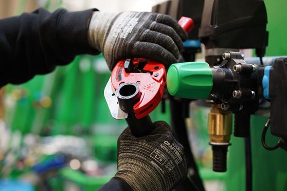
a. Hoses fitted to valve inlet/outlet manifolds are to be heated until pliable but not melting, then fastened with worm-drive hose clamps. Place hose clamps at the bottom barb of hose tail. Small amount of silicone grease can be used to assist.


 Tuck cable-splitting block behind valves and fasten to valve mount using the provided cable-ties. Tilt valve mount back to verticle and re-tighten M12 bolts.
b. There are four 25mm (1”) ID black high-pressure hoses to be attached to the valve-bank:


• One “pressure” hose exiting pump outlet or ErgoMax™ ball valve (if fitted)
• Three “bypass” hoses returning to tank. Two of these (long and short) enter the 25mm (1”) OD “Y” fitting which flows into the MixMax™ ball valve attached to chassis above right-hand linkage point, while the other returns directly to tank.
c. Inlet manifold of master-valve is identified by a vertical “up” arrow adjacent to green regulator knob. Ensure pressure hose is fitted to this manifold.

d. Longer bypass hose attached to topmost inlet of the “Y” fitting to be fitted to the master-valve bypass (90-degree hose-tail) located at the rear of the valve


e. Shorter bypass hose attached to bottommost inlet of the “Y” fitting to be fitted to the pressure adjuster valve (grey banded) bypass (with brass check valve).
f. Leftmost hose is to be fitted to section bypass manifold, to the right of red knobs.
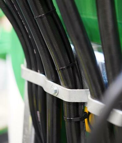
5. Secure valve loom to pressure adjuster bypass hose with cable-ties, having it come out on the right-hand side of the longer galvanised clamping bracket. Secure below bracket with large cable-tie to prevent chafing.
a. Hoses fitted to valve inlet/outlet manifolds are to be heated until pliable but not melting, then fastened with worm-drive hose clamps. Place hose clamps at the bottom barb of hose tail. Small amount of silicone grease can be used to assist.
6. Fit 13mm (1/2”) ID hoses to section valve hose tails
