13 minute read
The STAMPED Method for Selecting Tubing and Fittings for a Metal Tube Assembly


The acronym “STAMPED”, as used for hose assemblies, is equally as important to use when developing tube The acronym “STAMPED”, as used for hose assemblies, is equally as important to use when developing tube The acronym “STAMPED”, as used for hose assemblies, is equally as important to use when developing tube assemblies. The same factors apply; only the fabrication and installation will vary. Flow and pressure charts assemblies. The same factors apply; only the fabrication and installation will vary. Flow and pressure charts assemblies. The same factors apply; only the fabrication and installation will vary. Flow and pressure charts The can be found from the same technical references. Typical tubing charts are included in Task 7. Size of the tubing is based on: can be found from the same technical references. Typical tubing charts are included in Task 7. Size of the tubing is based on: can be found from the same technical references. Typical tubing charts are included in Task 7. Size of the tubing is based on: S T A M P E D 1. Flow (GPM) 2. Flow velocity (ft/sec) 3. Pressure 4. External corrosion All hydraulic tubing is measured on the outside diameter (O.D.). The flow velocity is based on the gallons per minute (GPM) flowing through the tube. This can be calculated or found on charts and in technical references. V = velocity (ft/sec) A = internal area (sq. in.) (p x r 2 ) or (D 2 x .7854) Q = gallons per minute (GPM) p = 3.1416 1. Flow (GPM) 2. Flow velocity (ft/sec) 3. Pressure 4. External corrosion All hydraulic tubing is measured on the outside diameter (O.D.). The flow velocity is based on the gallons per minute (GPM) flowing through the tube. This can be calculated or found on charts and in technical references. V = velocity (ft/sec) A = internal area (sq. in.) (p x r 2 ) or (D 2 x .7854) Q = gallons per minute (GPM) p = 3.1416 1. Flow (GPM) 2. Flow velocity (ft/sec) 3. Pressure 4. External corrosion All hydraulic tubing is measured on the outside diameter (O.D.). The flow velocity is based on the gallons per minute (GPM) flowing through the tube. This can be calculated or found on charts and in technical references. V = velocity (ft/sec) A = internal area (sq. in.) (p x r 2 ) or (D 2 x .7854) Q = gallons per minute (GPM) p = 3.1416
Pressure is included in sizing here as well as under the “P” later on in “STAMPED”. Pressure is included in sizing here as well as under the “P” later on in “STAMPED”. Pressure is included in sizing here as well as under the “P” later on in “STAMPED”. Flow losses (pressure Flow losses (pressure Flow losses (pressure drop) can affect sizing the tubing. Length of line and configuration (elbows and number of fittings) can add drop) can affect sizing the tubing. Length of line and configuration (elbows and number of fittings) can add drop) can affect sizing the tubing. Length of line and configuration (elbows and number of fittings) can add to pressure losses dictating a larger tube I .D. Low tem peratures can also affect viscosity which in turn will to pressure losses dictating a larger tube I .D. Low tem peratures can also affect viscosity which in turn will to pressure losses dictating a larger tube I .D. Low tem peratures can also affect viscosity which in turn will Method for Selecting Tubing and Fittings affect pressure drop. Wall thickness at bent tube sections will have reduced wall size. This will require the designer to determine the amount of reduction based on the bend radius and to recalculate allowable working pressure for the particular bend. On some applications where corrosion is anticipated, the life of the affect pressure drop. Wall thickness at bent tube sections will have reduced wall size. This will require the designer to determine the amount of reduction based on the bend radius and to recalculate allowable working pressure for the particular bend. On some applications where corrosion is anticipated, the life of the affect pressure drop. Wall thickness at bent tube sections will have reduced wall size. This will require the designer to determine the amount of reduction based on the bend radius and to recalculate allowable working pressure for the particular bend. On some applications where corrosion is anticipated, the life of the for a Metal Tube Assembly system can be extended by increasing the wall thickness to compensate. Temperature can be a factor with tubing and fittings, but usually not until temperatures are extreme (350° system can be extended by increasing the wall thickness to compensate. Temperature can be a factor with tubing and fittings, but usually not until temperatures are extreme (350° system can be extended by increasing the wall thickness to compensate. Temperature can be a factor with tubing and fittings, but usually not until temperatures are extreme (350° F to -45° F). High and low temperatures can affect O-rings in fittings and the selection of tubing.F to -45° F). High and low temperatures can affect O-rings in fittings and the selection of tubing.F to -45° F). High and low temperatures can affect O-rings in fittings and the selection of tubing. ASSEMBLY COMPONENT SELECTI ON
The acronym STAMPED, as used for hose assemblies, is equally as important to use when developing tube assemblies. The same factors apply; only the fabrication and installation will vary. Flow and pressure life. To fulfill the requirements of the application, additional questions may need to be answered such as: Application: Determine where the new or replacement tube assembly is to be used. Most often, only a duplicate of the original will be required provided the original assembly gave acceptable service life. To fulfill the requirements of the application, additional questions may need to be answered such as: Application: Determine where the new or replacement tube assembly is to be used. Most often, only a duplicate of the original will be required provided the original assembly gave acceptable service life. To fulfill the requirements of the application, additional questions may need to be answered such as: Application: Determine where the new or replacement tube assembly is to be used. Most often, only a duplicate of the original will be required provided the original assembly gave acceptable service life. To fulfill the requirements of the application, additional questions may need to be answered such as: 9.0. Use the “STAMPED” method in selecting proper tubing and fittings for a metal tube assembly. Outcome charts can be found from the same technical references. 9.1. Design and specify tube assembly Where will assembly be used Working and surge pressures Where will assembly be used Working and surge pressures Where will assembly be used Working and surge pressures components. Fluid/ambient temp. Fluid compatibility Fluid/ambient temp. Fluid compatibility Fluid/ambient temp. Fluid compatibility Gov. & industry standards Mechanical loads Gov. & industry standards Mechanical loads Gov. & industry standards Mechanical loads S ize of the tubing is based on: Suction application? Type of tubing Fitting type Suction application? Type of tubing Fitting type Suction application? Type of tubing Fitting type 1. Flow (GPM) 2. Flow velocity (ft/sec) The acronym “STAMPED”, as used for hose assemblies, is equally as important to use when developing tube assemblies. The same factors apply; only the fabrication and installation will vary. Flow and pressure charts Environm ental Minimum bend radius Routing Environm ental Minimum bend radius Routing Environm ental Minimum bend radius Routing Excessive abrasion Expected service life External corrosion Excessive abrasion Expected service life External corrosion Excessive abrasion Expected service life External corrosion 3. Pressure can be found from the same technical references. Typical tubing charts are included in Task 7. All hydraulic tubing is measured on the outside diameter (O.D.). The flow velocity is based on the gallons per minute (GPM) flowing through the tube. This can be calculated or found on charts and in technical references. aterial: Tube selection and fittings must be compatible with the fluid to be circulated in the system, as well as the environmental conditions. ressure: When selecting metal tube, it is vital to know the working pressure, including pressure Connector & Conductor Cetification• 55Study Manual- 07/ 01/ 16 Material: Tube selection and fittings must assure compatibility with the fluid to be circulated in the system, as well as the environmental conditions. Note: Many swivel elbow fittings contain O-rings which must be compatible with the fluid and environmental conditions. Connector & Conductor Cetification• 55Study Manual- 07/ 01/ 16 Material: Tube selection and fittings must assure compatibility with the fluid to be circulated in the system, as well as the environmental conditions. Note: Many swivel elbow fittings contain O-rings which must be compatible with the fluid and environmental conditions. Connector & Conductor Cetification• 55Study Manual- 07/ 01/ 16 Material: Tube selection and fittings must assure compatibility with the fluid to be circulated in the system, as well as the environmental conditions. Note: Many swivel elbow fittings contain O-rings which must be compatible with the fluid and environmental conditions. 4. External corrosion M P Note: Many swivel elbow fittings contain O-rings that of the tubing is based on: Flow (GPM) Flow velocity (ft/sec) Pressure External corrosion All hydraulic tubing is measured on the outside diameter (O.D.). The flow velocity is based on the galspikes. Pressure spikes greater than the published lons per minute (GPM) flowing through the tube. This can be calculated or found on charts and must be in technical references. V = velocity (ft/sec) A = internal area (sq. in.) (p x r Q = gallons per minute (GPM) 2 ) or (D 2 x .7854) working pressures will shorten the system service life and must be taken into consideration. Published tube working pressures must be equal to compatible with the fluid and environmental p = 3.1416 or greater than the system pressure. Thinning of conditions. the tube wall at bends must also be considered. Pressure is included in sizing here as well as under the “P” later on Burst pressures are reference pressures intended for Pressure is included in sizing here as well as under the “P” later on in “STAMPED”. Flow losses (pressure in STAMPED. Flow losses (pressure drop) can affect sizing the tubing. destructive testing purposes and design safety factors only. Typically, for can affect sizing the tubing. Length of line and configuration (elbows and number of fittings) can add to pressure losses dictating a larger tube I .D. Low tem peratures can also affect viscosity which in turn will Length of line and configuration (elbows and number of fittings) can dynamic hydraulic applications, the minimum burst pressure rating is affect pressure drop. Wall thickness at bent tube sections will have reduced wall size. This will require the add to pressure losses dictating a larger tube I.D. Low temperatures can four times that of the maximum working pressure rating. designer to determine the amount of reduction based on the bend radius and to recalculate allowable workalso affect viscosity, which in turn will affect pressure drop. Wall thicking pressure for the particular bend. On some applications where corrosion is anticipated, the life of the ness at bent tube sections will have reduced wall size. This will require the designer to determine the amount of reduction based on the bend E nds: Identify the tube end fittings using manufacturers’ catalogs. system can be extended by increasing the wall thickness to compensate. emperature can be a factor with tubing and fittings, but usually not until temperatures are extreme (350° radius and to recalculate allowable working pressure for the particular bend. On some applications where corrosion is anticipated, the life of the system can be extended by increasing the wall thickness to compensate. D elivery: Availability, time to assemble, special packaging, ship ping, and documentation. F to -45° F). High and low temperatures can affect O-rings in fittings and the selection of tubing. pplication: Determine where the new or replacement tube assembly is to be used. Most often, only a duplicate of the original will be required provided the original assembly gave acceptable service life. To fulfill emperature can be a factor with tubing and fittings, but usually not until temperatures are extreme (350° F to -45° F). High and T the requirements of the application, additional questions may need to be answered such as: Where will assembly be used Fluid/ambient temp. Gov. & industry standards Test Your Skills low temperatures can affect O-rings in fittings and the selection Working and surge pressures Fluid compatibility Mechanical loads of tubing. Suction application? Environm ental Excessive abrasion 1. All hydraulic tubing 2. Anticipating a corrosion Type of tubing Minimum bend radius Expected service life is measured by its: problem one could: pplication: Determine where the new or replacement tube assembly is to be used. Most often, only a duplicate of the original will be required, provided the original assembly gave acceptable service A a. O.D. b. I.D. c. Wall thickness. Fitting type Routing External corrosion aterial: Tube selection and fittings must assure compatibility with the fluid to be circulated in the system, as well as the environmental conditions. a. Increase volume. b. Decrease volume. c. Increase pressure.
d. Material hardness. d. Decrease wall thickness.
e. Material type. Many swivel elbow fittings contain O-rings which must be compatible with the fluid and environmental e. Increase wall thickness. conditions. 6 Study Manual- 07/ 01/ 16 AUGUST 2020 Connector & Conductor Cetification• 55 See correct answers on page 39.
Robert Sheaf has more than 45 years troubleshooting, training, and consulting in the fluid power field. Email rjsheaf@cfc-solar.com or visit his website at www.cfcindustrialtraining.com. Visit www. fluidpowerjournal.com to view previous problems.
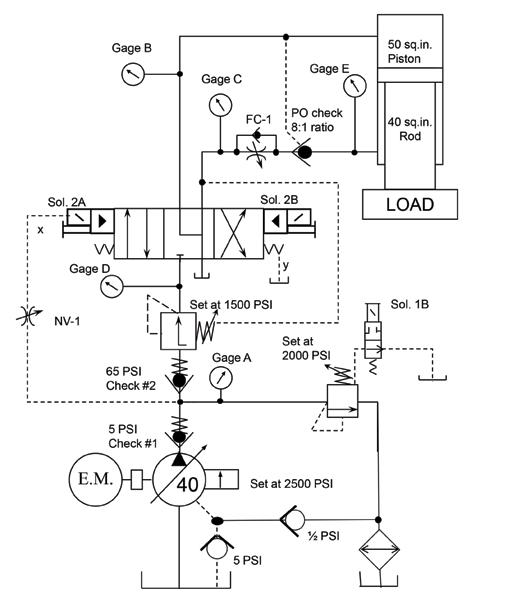
New Problem: Ram Does Not Retract on a Forming Press
By Robert Sheaf, CFPAI/AJPP, CFPE, CFPS, CFPECS, CFPMT, CFPMIP, CFPMMH, CFPMIH, CFPMM, CFC Industrial Training
»THE CIRCUIT SHOWN HERE was a press I designed some years ago. A problem developed with the ram not returning after forming a steel truck bumper. The pressure-reducing valve that was leaking out of the pressure adjustment screw was replaced with one from the company’s stock. It was the D08 module located under the main directional valve.
The pressure-reducing valve setting was adjusted to accommodate the different bumper designs. If the pressure was too high when pressing, the ram die would cause the material to tear. Each bumper design had a specific tonnage that would work well in the forming process.
When the new valve was set to pressures below 1,200 psi, the ram could not be pulled off the formed bumper. The operator would have to increase the pressure on the reducing valve to about 1,700 psi to get the ram to retract. Once off the formed bumper, the press would retract with less than 900 psi.
What could be the solution? S Solution to the May 2020 problem:
Strange Noise when Starting a Hydraulic Motor
When you normally experience noise in a system at start up, it usually is an air problem. A few months earlier, I was troubleshooting a power unit that was noisier than two identical units nearby. The units had hinged tops on the reservoirs, and the noisy one had a bad problem of aeriated oil. But there were no areas with a small amount of oil on the floor, indicating where air could inter when the unit was running. I smeared #2 grease on each of the joints on the intake line while it was running. I found that one joint with grease quieted down for 15 to 30 seconds each time I greased it. Resealing that joint solved the problem. I did the same thing to the new hose on the rolling mill and found that one hose fitting was causing the problem. Air can get in where oil will not leak out.
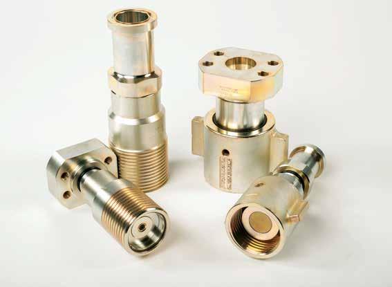
New! quality matters. every time.
FLAT FACE DESIGN “TVF” SERIES QUICK DISCONNECT
• Up to 6,000 PSI Operating Pressure—Coupled or Uncoupled • Full 4:1 Safety Factor • Superior Flow Characteristics—Minimal Pressure Drop • RoHS Compliant Plating • Multiple Port Options—Female NPTF, Female SAE O-Ring, Female BSPP, Code 61 & 62 Flange Port/Head
P.O. Box 6479, Fort Worth, TX 76115 V. 817/923-1965 www.hydraulicsinc.com DURABLE. RELIABLE. HOSE, CORD, & CABLE PRO GRADE REELS

SOLUTIONS FOR : AIR / WATER | HYDRAULIC | PNEUMATIC | VACUUM | WELDING | POWER
AND MORE
www.coxreels.com


