8 minute read
Hybrid Electric with a Smart Platform Source Modeling
Zoe Tigana Mandimby Junior, Liva Graffin Rakotoarimanana, Eulalie Odilette
Rafanjanirina, Minoson Rakotomalala, Zely Arivelo Randriamanantany
Advertisement
Institute for Energy Management (IME), University of Antananarivo, PB 566, Antananarivo 101, Madagascar
Received: 07 Apr 2023; Received in revised form: 02 May 2023; Accepted: 12 May 2023; Available online: 20 May 2023
Abstract This paper develops how to manage and to save electric energy produced by hybrid sources. Research focuses on the detailed hybrid system component modeling. HOMER software is used for study feasibility and RETScreen software for results validation. Smart platform automatically chooses energy sources to be used by a home electric system in prioritizing renewable energy. Multi-sources system includes photovoltaic, wind turbine and generator. Switching and control between thermal and renewable energy sources are ensured by a microcontroller. Based on electric energy need, modeling can manage various energy sources by running each source independently showing its best performance. Therefore, this research allows the chosen villages to get out of blackout stress thanks to smart platform which is able to provide high availability of electricity from a hybrid system combined with battery storage.
Keywords Electric energy, renewable energy, thermal energy, battery storage
I. INTRODUCTION
Nowadays, diesel generator is the most widely used technique for isolated sites electrification However, access to these sites is usually long and difficult Moreover, maintenance costs and fuel supply are very high. Solution consists to link hybrid system and diesel generator with two renewable energy sources (Wind Power, PV). Again, this solution is often the most cost-effective option. This paper focusesonproviding permanent powersupply ofanisolated site which may be located on various sites in Madagascar. RETScreen software sized the system and detailed modeling of hybrid systems and its system componentsincluding theentiresystem study arepresented
II. METHODOLOGY
2.1. Hybrid systems overview
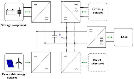
Hybrid systems are characterized by system function principle, by used various sources and whether exists storage device presence. Wind, solar or hydraulic energy are most frequently associated with a generator in hybrid systems involved a source of renewable energy. They are often autonomous, as they are made for isolated sites. Theoverallelectrichybrid system can bestructured as shown in figure 1. In this structure, sources and outlays can be added or removed according to the system topology. The powergridorthefuelcellcouldbeforexampletheauxiliary source [1].
Fig 1: Hybrid system structure
There are three most popular hybrid systems in the world:
• Hybrid systems combining renewable energy sources: This option usually groups either wind combined with solar energy or hydropower with wind energy Wind energy exploitation lays on its high availability whereas sun energy is available only few hours a day. Among these two options, the firstoption ismoreinterestinginsuch way thatmany authors have conducted work and studied on the modeling of this system [2].
• Hybrid systems combining renewable energy sources with conventional energy sources: The electricalgenerationsystemusing dieselgeneratoras an additional energy is often the case in electric hybrid system. Conventional generators are used as backup generators in the system. Although, it is more cost-effective in isolated sites, model assessment can be more complex. Since, this system is conceived from the intermittency of renewable energy, it should use extra generators, [3].
• Hybrid systems combining renewable energy with storage systems: Associated with a storage system, this system reduces the problems related to climate variations. Studies made by several authors indicate that this system requires good management of these sources, [4]. Electric hybrid system configuration varies according to the process principle. Its configuration is based on buses (bus CC or CA or CC/CA). Some related study states configuration examples, [5], [6].
A. Photovoltaic cell modeling [7] [8]
Figure 2 shows the basic solar cell model, [5]. This model represents the principle of sun light energy conversion into electric energy.
B. Wind energy modeling
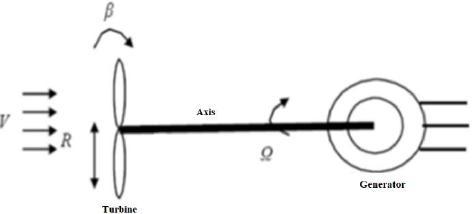
Wind turbines convert aerodynamic energy into electric energy. In a wind turbine two conversion processes take place. The aerodynamic power (available in the wind) is converted into mechanical power and then, again converted into electric energy. Wind systems facilities produce powers from kW (for mini wind systems) up to MW (for large wind systems) The kinetic energy in the wind is converted into mechanical energy by torque production. Since the energy provided by the wind is of kinetic energy, its amplitude depends on both air density and wind speed. Figure 3 shows a wind turbine model, [5].
The wind kinetic energy is given by the formula: CE where, m: mass of air (m= ρ.V.S.dt) [kg], ρ: density of the air [kg m-3],
S: blades surface [m2],
V: wind speed [m s-1]
Knowing that Pw is the power developed by the turbine as
By applying node’s law to this circuit, intensities of circuit I and on diode Id are given by: d ph I I I = (1) (
(2) where,
I ph: electric power generated by the light [A]
Iod : Intensity of diode saturation power [A]
RS: Resistance series [Ω] k: Boltzmann constant (k = 1, 38.10-23) q: electron charge (q = 1, 602.10-19 C)
T: Cell temperature [K]
Let Cp be the quotient between the mechanical power Pm and the power developed by the turbine Pw The mechanical power is less than the developed power, and:
Cp depends on the speed ratio λ, the turbine rotation speed (which depends on specific speed), and blade inclination angle β. The mechanical power recovered at the wind turbine is given by:
C. Battery model
The following electrical parameters characterize model battery:
• Ampere-hours (Ah) rated capacity C can be extracted from battery, under predetermined conditions of discharge.
• Charge status
• Charging (or discharging) plan which is the parameter reflected by the fraction between the battery nominal capacity and the electric power whether it is charged or discharged.
A generator modelling takes account combustion engine and electric generator’s association The type of fuel and the power delivering ability make generators different from one another In this study, Diesel Generator (DG) is used as its fuel consumption which varies linearly with consumed power as it refers in manufacturer data. The modeled generator is SIDERIS brand having power 2.5kVA with a range of 1.5 l/h, [9]. To model Diesel Generator, consumption-based simulation on the generator rated power is applied.
E. Microcontroller
According to BIGONOFF, microcontrollers are microprocessor type units for information treatment to which are added internaldevices allowing their components to make edits deprived of adding internal components [10]. Today, they are located in most professional or public applications according to their need. Among the mostly used microcontrollers, there are:
• CMOS microcontrollers as the PIC 16F84A of Microchip [11],
• 16HC11 of Motorola with a large number of devices such as counters, PWM, digital analog converters, digital inputs and outputs, serial links, etc.
• Microcontrollers based on the 8051 architecture from Intel (ST, Atmel, Philips) with their advanced calculation capabilities. This family of microcontrollers has 8 bits and is an industry standard in its own right.
• Arduino microcontroller, FPGA and the raspberry. These are advanced platforms
III. RESULTS
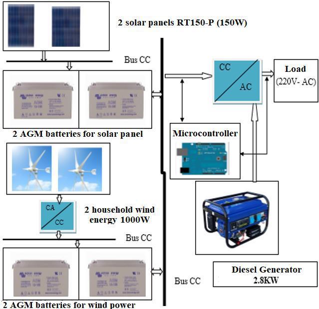
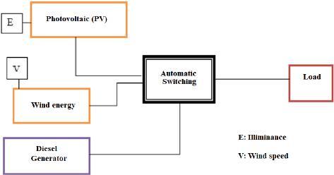
The hybrid system representation state is a powerful tool to model linear or non-linear system operation in continuous or discrete-time. It also has the advantage of maintaining the chronological representation of the phenomena [12], [13]. Figure 5 shows the hybrid system structure in smart platform
5: Hybrid system structure
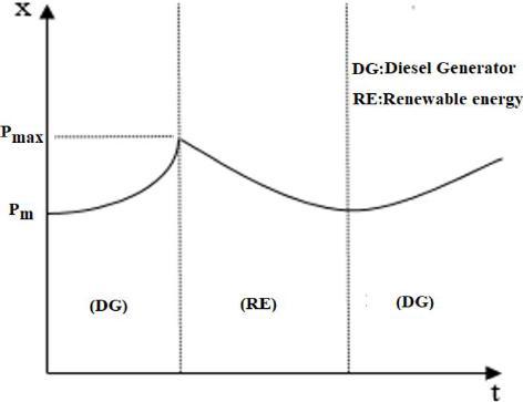
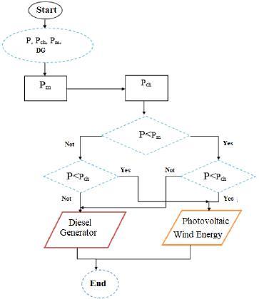
The hybrid system consists of photovoltaic, wind energy, and diesel generators Produced power by two renewable sources depends on the illuminance E and on the wind speed V. Vm and Em are respectively the startup speed of the turbine and the minimum value of the illuminance. The renewable source stopped automatically when the sensor detects the electrical power line Pm corresponding to high values where power rises above the lower threshold. The switching system forms a dynamic system which in continuous evolution with power variation P = x, and in discrete evolution with transition running passage from renewable system to generator. Power curve P = x according to type of load is modeled in Figure 6.
Fig 7: Condition swapping energy model
Since ideal condition for the system operation has been considered, evolution model can be determined. It requires very accurate sensor (power sensor) or gauge circuit to detect the switching threshold Pm and the energy used by the outlay Pch. Once this threshold is detected, system state changes instantly
System control
The system control model is described by equation (8) where:
• x = x1 when only Diesel Generator runs, and
• x = x2 when PV and wind power run
The hybrid system control equation becomes matrix equation as follow:
Fig 6: Renewable system power path
Power evolution can be modeled by the following differential equations: with a and k are two real positive nonzero constants.
Passage from one state to other is triggered by Pm value as it is shown in Figure 7
Assume that B =( and A =
, the command matrix [A] (B) [A] 2 (B)..., [A]n-1 (B) are of full rank And if this command matrix is linearly independent, then the electric hybrid system is completely controllable [12].
G. Switching
The autonomous switching is characterized by the phenomenon where the system state changes discontinuously when the power produced by renewable sourcereachesathresholdorislessthan theenergyrequired by the load Switching system function displays on Figure 8
H. Modeling with simulink
a. Photovoltaic generator
Photovoltaicgeneratorsimulation usesmathematical equation to build simulink model to characterize a photovoltaic cell. Model corresponding Simulink block diagram is shown in Figure 9
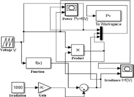
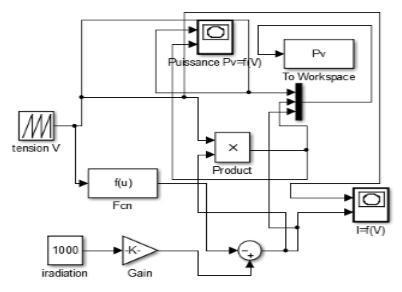
Based on the photovoltaic cell model in Figure 9, RT-150P module composed by 4 groups block model of 9 cells connected in parallel (36 cells) displays in Figure 10. This model is based on an equivalent electrical circuit with the Matlab/Simulink software
According the curves in Figure 11, a photovoltaic cell provides 1A electric current and voltage 0.6V atthe cell terminals. Using module RT-150 P composed of 4 x 9 cells, Figure 12 shows voltage and power characteristics.
Using 36 photovoltaic cells, Figure 11 shows solar irradiation I(A) and Power-voltage pace Pv(W) characterizing photovoltaic cell. These curves are obtained from Pv = f (V) and I = f (V) at medium irradiance 1000W/m2 and temperature T = 25oC.


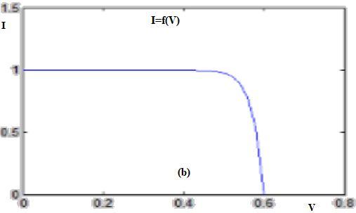
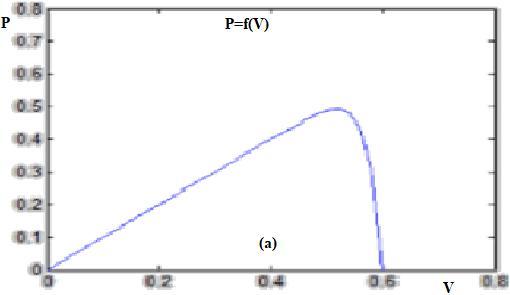
The characterization of the photovoltaic cell has been defined for illuminance E = 1000W/m2 and temperature T = 25 ° C. Power curve characterizing a photovoltaic panel depends on the variation of current- voltage (Figure 12(a)). Power reaches a maximum peak 140W when current-voltage at 12V Besides, the current is maximum at the open circuit (voltage zero) and zero at the maximum voltage (Figure 12(b)).
Figure13showstheblockpatternofthewindturbine to simulate its operation.
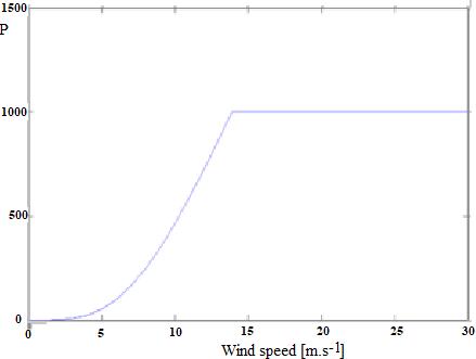
For the wind turbine, electric power production rises with wind speed till it reaches the highest threshold 1000W, (Figure 14) c. Arduino microcontroller model
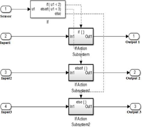
Arduino microcontroller is used for switching circuit command. Its block model under Matlab/Simulink that represents the system (sensor - Arduino-Relay) is shown in Figure 17

The maximum power or nominal power Pn produced by the wind generator is obtained from nominal speed Vn ≈14 m.s-1 (50.4 km.h-1). The startup speed Vd is 2 m.s-1 .
Arduino output values of Arduino-sensor model (Figure 17) according to data delivered by current sensor is represented on table 1.
Diesel Generator model
Using the Arduino model, current intensities are displayed on microcontrollerdigitaloutput.Timeoffsetwas set to 0. Captured graphs of output 1, output 2 and output 3 with current intensities I<4A, I<6A and I>=6A are shown in Figure18 (a), (b), (c) respectively
After developing all components of hybrid system like hybrid source and switch module, it remains to connect thesecomponentstofindoutoverall system functioningand carry out an analysis according to various parameters related to the system (load, battery state, climate data, etc.). Figure 19 illustrates the whole block

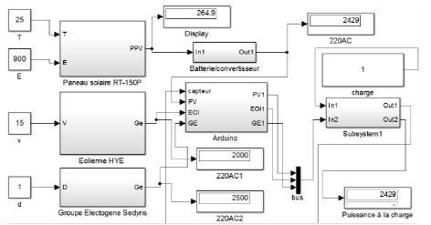
Daily Load profile
During the day, load electric power varies and is not constant throughout theday. Table 2 presents estimate daily energy needs of a given household It describes electricity demand from the site that includes light and other electrical devices. The daily energy consumption Ec of a household estimate about 2332W
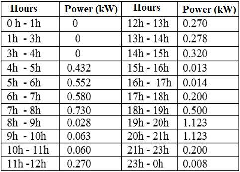
Table 2: Estimate daily energy consumption of a household
Block model of hybrid system analysis is performed through simulation in varying load power. When power load grasps 500W (Figure 20 (a)), hybrid system connected load is average. Similarly, if power load rises up to 1000W (Figure 20 (b)), connected load is still considered to be average. In these cases, renewable sources itself fits to ensure the power supply in order to satisfy load capacity But if power load becomes greater than 2000W (Figure 20 (c)), energy needs have to be powered by Diesel Generator.
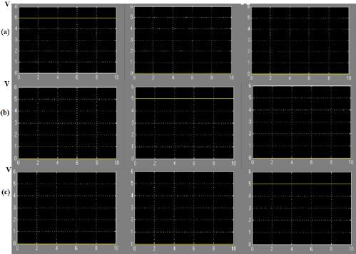
Assume that the daily load distribution is given by the Table 3.
Table 3: Daily load profile

