18 minute read
A Review of Laminated Object Manufacturing (LOM) Aspects and Various Processes used in It
Hassan Asad, Khan Ihsanullah
Department of Mechatronic Engineering, Jiangsu Normal University, China
Advertisement
Received: 16 Dec 2022,
Receive in revised form: 11 Jan 2023,
Accepted: 17 Jan 2023,
Available online: 23 Jan 2023
©2023 The Author(s). Published by AI
Publication. This is an open access article under the CC BY license (https://creativecommons.org/licenses/by/4.0/).
Keywords Laminatedobjectmanufacturing (LOM), Adhesive layers, Laser cutter, Machining,Prototyping.
Abstract The purpose of this review is to present a break-through technology named Laminated Object Manufacturing (LOM), which can produce a real three-dimensional object directly from a CAD model in a matter of hours. The present paper discusses the rationale for this technology describes the LOM process and presents an overview of LOM machines currently available on the market. Software interfaces and the use of various materials are discussed as well. The laminated object manufacturing LOM process is an effective rapid prototyping technology with a variety of application possibilities. Applying LOM in rapid tooling and patternmaking is especially advantageous because of the LOM objects, robustness, their wood-like properties, and their comparably low material costs. This review paper presents an extension of the sheet lamination object manufacturing process by using a robotic cell to perform the sheet manipulation and handling as well as proposes a frozen slurry-based laminated object manufacturing (FS-LOM) for processing porous ceramics.
I. INTRODUCTION
It is a 3D-printing technology developed by Helisys Inc. (now Cubic Technologies). In it, layers of adhesive-coated paper, plastic, or metal laminates are successively joined together and cut to an appropriate shape with a laser cutter. Objects printed with this technique may be additionally modified by machining after the printing process. [1,2,] The typical layer resolution for this process is defined by material feedstock and usually ranges in thickness from many sheets of paper to a copy. Laminated object manufacturing (LOM) is one of the most popular rapid prototyping (RP) techniques in terms of speed and costeffectiveness
II. RATIONALE
In a concurrent engineering environment, a multidisciplinary team whose members cover all aspects of product development including design, manufacturing, qualitycontrol, finance,marketing,etc.isformed atan early phase tobringaproduct to market better,faster, and cheaper than the competition.
Efficient communication and computer integrated tools are two key factors required to fulfill this task, and, although a computer-generated 3-D image may well serve the purpose, a real physical replica of the part is often more persuasive and useful. [3]
LOM technology has been developed to manufacture a real part from its CAD model rapidly and inexpensively [4,14,26] Through LOM's software, the CAD model is sliced horizontally into a stack of thin layers, each layer representing an average cross-section at a given height [1]. A laser beam then cuts the periphery of each cross-section from a continuous sheet of material, one layerat a time from the bottom up. Every cut is automatically and precisely attached to its predecessor. Eventually, a three-dimensional object is built in this layer-to-layer fashion.
LOM technology belongs to a new field variously called Rapid Prototyping, Desktop Manufacturing, Freeform Fabrication, etc. Other technologies belonging to this category include a similar layer-to-layer idea, yet utilize different approaches. 3D System's Stereo Lithography has pioneered this industry, using a laser that solidifies liquid photopolymer to form successive layers. The unpredictable shrinkage due to solidification, the extra effort needed to create support structures for overhanging portions, costly and limited material availability, and long production times aresomeofitsdrawbacks.Manycompanies havedeveloped similar systems. Another approach using liquid polymer has been incorporated into Cubita's solider system. Here a flood lamp and photomasks are used to expose a layer of liquid photopolymer in a flash. The non-activated polymer is then replaced by wax, and a milling head cuts the surface down to a precise thickness. This procedure is repeated until a part is completed [5,9]. The complexity of this system is its main drawback. Selective Laser Sintering (SLS) utilizes powder materials as media, which melt and resolidify when sintered by a laser. Here the main problems are shrinkage and warpage due to internal stress. In Stratasys's Fused Deposition Modeling system, a thin thermoplastic wire is fed through an extruding head, and droplets of molten material are then deposited into layers to form a part. Supporting structures are required in this process. [6] Perception Systems Inc's Ballistic Particle Manufacturing employs a similar idea. Another technique discovered by MIT uses an ink-jet printer head to spread the adhesive onto a layer ofpowdered material; the powder soaks the adhesive thus forming a layer. This technique is still in the research stage.
III. BASIC CONCEPT OF THE LOM PROCESS
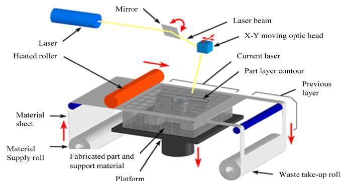
In the Laminated Object Manufacturing (LOM) process, three-dimensional objects are manufactured by sequentially laminating and cutting two-dimensional cross-sections. The mediumused inLOMprocessesconsistsofadhesive-coated sheet materials. Fig. 1 shows a typical type of the LOM process. The LOM process is performed by layered manufacturing as in other AM. The main components of the LOM machine are a feed mechanism that advances a sheet over a build platform, a heated roller to apply pressure to bond the sheet to the layer below, and a laser to cut the outline of the part in each sheet layer. Parts are produced by stacking, bonding, and cutting layers of adhesive-coated sheet material on top of the previous one. A laser cuts the contour of the part into each layer according to prepared CAD data [7,8] After each cut is completed, the platform is lowered by a depth equal to the sheet thickness, and another sheet is loaded on top of the previously deposited layers. The platform then rises slightly, and the heated roller applies pressure to bond the new layer. The laser cuts the outline, and the process is repeated until the last layer.
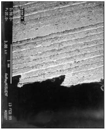
As shown in Figure 2, the sheet material holds the adhesive either on one or on both sides and contains the adhesive within itself like woven composite material impregnated with a bonding agent. The adhesive, which can be precoated onto the material or deposited before bonding, enables layers of sheet material to adhere to each other to so constructing a three-dimensional object. Fig. 2 shows a surface profile of the part fabricated by LOM technology. Stairsteps are clearly shown on the surface of the part due to stacking the sheet layers. This phenomenon is known as the “stair-stepping effect” and is found generally in AM. The surface profile is changed by the variation of surface angle on inclined surfaces. That is to say, the profile is even closer to the vertical surface and, is rougher closer to the horizontal plane. The curved shape machined by laser cutting is shown in the outline of each layer. It is estimated that the curve form is influenced by the Gaussian laser beam deduced an equation by assuming that the absorption of laser radiation within the resin follows the Beer-Lambert law and took the shape of the cured resin into accountintheworkingcurveinSL,asgiven inEq.(1).Each variable x and y denotes the length from the center of the Gaussian laser beam in the radial direction and a normal distance from the resin surface to the cured depth. The coefficients a, b and c are constants determined by the characteristics of the laser beam and material resin.
ax2 + by + c = 0 (1)
Using Eq. (1), showed that the edge profile of the layer machined by laser can be a parabolic curve in LOM . The magnified surface profile also supports the approach, as shown in Fig. 2. Thus, the edge profile is subordinated by Eq. (1). After a layer is deposited, the peripheral shape of this layer's cross-section is cut by a laser beam from the information provided by the CAD model. This bondingbefore cutting procedure is repeated until the full height of the part is reached (Figure 2).
IV. PROCESSES
Manydifferent3Dprintingprocesses andtechnologieshave been invented since the late 1970. The printers were originally very large and expensive in what they could produce. [9] A large number of Additive manufacturing processes are now available.
4.1. Robotic cell for performing sheet lamination-based additive manufacturing
Advances in material science and manufacturing technologies are leading to significant improvements in the way we design and manufacture products. Many applications require structures composed of layers of heterogeneous materials and prefabricated components embedded between the layers. The existing additive manufacturing process based on layered object manufacturing is not able to handle multiple layer materials and cannot embedprefabricated components. Moreover, the existing process imposes restrictions on the material options. This significantly limits the type of heterogeneous structures that can be manufactured using traditional additive manufacturing. The latest research presents an extension of the sheet lamination object manufacturing process by using a robotic cell to perform sheet manipulation and handling. It makes the following three advances: (1) enabling the use of multi-material layers and inclusion of prefabricated components between the layers, (2) developing an algorithmic foundation to facilitate the automated generation of robot instructions, and (3) identifying the relevant process constraints related to speed, accuracy, and strength. We demonstrate the system’s capabilities by using three case studies. Fabrication of complex geometric structures is made possible due to advances in additive manufacturing. Additive manufacturing has become capable of building complex parts with heterogeneous materials.
Heterogeneous structures are composed of many different materials to obtain the desired functional properties [10,11] They are beneficial in several applications, for example, to provide thermal insulation as well as supporting mechanical loading in aerospace structures. Such structures can be manufactured using additive manufacturing. In additive manufacturing (AM), parts are created by depositing material layer-by-layer using computer control. VAT photopolymerization, powder bed fusion, binder jetting, material jetting, sheet lamination, material extrusion, and direct energy deposition are the seven types of AM classified by the American Society for Testing and Materials (ASTM). The sheet lamination process can be classified into the following two categories: (1) laminated object manufacturing and (2) ultrasonic consolidation. Laminated object manufacturing (LOM) is one of the oldest additive manufacturing processes. Objects are made from prefabricated layers [12,31] Therefore this method is fast compared to pixel-based AM methods. However, the traditional LOM method is not able to work on multimaterial structures. This limits the kind of structures that can be produced using LOM.
Realizing a sheet lamination based additive manufacturing cell-based on robots offers the following benefits:
• It allows the use of different materials for different layers.
• It enables the addition of prefabricated components between laminated sheets.
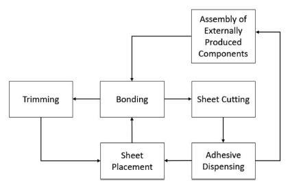
The use of robots adds new functional capabilities to the LOM process (required to manufacture heterogeneous structures). At the same time, the process of planningfor the system becomes significantly more challenging due to the use of robots. Converting object manipulation requirements to robot trajectories is computationally challenging. Robot trajectories need to meet robot joint limit and joint speed constraints, avoid singularities and produce consistent paths [13]. As a part of our preliminary investigation, it is demonstrated how robots can be used to execute sheet lamination-based AM. Research develops a general system for performing sheet lamination-based additive manufacturing for a heterogeneous component. Ideas and methods from existing areas of LOM are integrated into the design of a robotic cell that performs the following manufacturing process steps: (1) sheet placement, (2) sheet cutting, (3) assembly of externally fabricated components, (4) adhesive dispensing, (5) bonding, and (6) trimming. It also presents an approach for addressing the challenging process planning required for the robotic cell to perform each step. This consists of (1) generating each layer from a mesh of the structure, (2) generating the tool path and trajectory using contour tracing, (3) generating the trajectory of the robot arm from the tool trajectory, (4) generating assembly instructions, (5) generating the trajectory for point-to-point motion using an optimizationbased algorithm, and (6) sequencing the robot motion for the six process steps.
Finally, it characterizes the relevant process constraints related to speed, accuracy, and strength, and presents three case studies: (1) a flexible wing for an unmanned aerial vehicle (UAV), and (2) a multi-layer insulation (MLI) blanket (3) a scaled aircraft wingtip.
4.1.1. Design of additive manufacturing cell
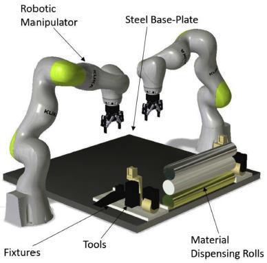
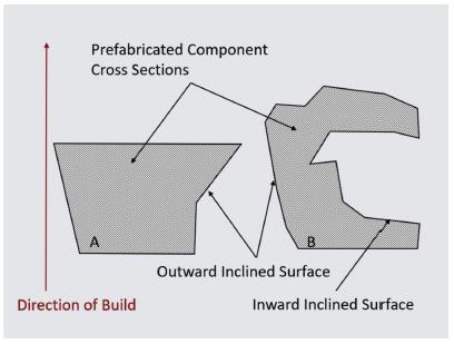
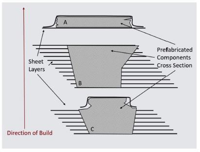
The cell concept is shown in Fig. 3. A block diagram indicating the manufacturing process steps is presented in Fig. 4. We can use multiple materials for different layers andembed prefabricatedmaterialsbetween layersusingthis cell. The work we have done in the inclusion of prefabricated materials can handle three types of cases (see Fig. 5). (A) If the thickness of the prefabricated component in the direction of the build is less than or equal to some threshold (decided by the material sheet properties), it is sandwiched between sheets. (B) If it is greater than that threshold it needs to be inserted. Such insertion is only possible if the component does not possess an inward slope in the direction of the build (see Fig. 6). (C) A hybrid of cases A and B.
Methodology
The cell executes the following basic steps:
1 Sheet Placement: This process step allows the selection of materials for the laminated layers. A steel base plate is mounted on the same plane as that of the 7-DOF robot. Different sheet material rolls, tools, and fixtures are housed in the base plate. [14,15] Having robotic manipulators provides the flexibility to select the material of the current layer.
The selected material is pulled from the roll by the robotic manipulator with the assistance of a force-sensitive gripper. The sheet is then placed on the steel base plate and clamped using magnetic clamps. Our designed setup illustration for the basic process is shown in Fig. 7. While performing sheet placement operations the problem of sheet draping or wrinkling might arise in the case of thin-walled sheets. We suggest the use of a flat gripper attachment to increase the gripping area (see Fig. 7) and the material dispensing rolls with torsion springs to get a wrinkle-free sheet. This will allow us to have enough tension in the sheet while placing it on the build platform to avoid any wrinkling or draping A second manipulator as shown in Fig. 3 or a human operator can clamp the sheet while it is being held in tension by the first manipulator.
2 Sheet Cutting:
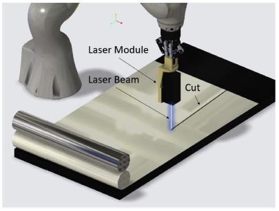
The illustration of the sheet cutting step is shown in Fig. 8 It is the second step in the sheet lamination-based additive manufacturing system. A pulsed laser module controlled by the onboard transistor-transistor logic (TTL) circuit is used in our setup. For cutting different materials, the power can be varied by a pulse width modulated (PWM) signal generated using a microcontroller. [16] A laser module is mounted on the robotic arms end effector.
As the violet laser beam is generated and the end effector moves over the sheet at a constant speed, a fine cut is obtained. The speed and duty cycle of the laser are adjusted based on the material type, thickness, and cut quality. is placed them back at this location before executing the next step. The illustration of the assembly step is shown in Fig. 9.
Moreover, as mentioned before it should be noted that the shape of the prefabricated component and build direction of the part is such that the part can be easily sandwiched between the layers or can be inserted from the top [17,18]
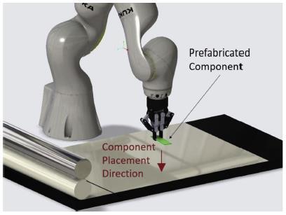
3 Assembly of Externally Fabricated Components: This process step allows the addition of prefabricated components between the laminated layers. The assembly process is divided into three parts.
• The first part is the placement of magnetic fixtures on the steel base plate for accurate assembly of the prefabricated components.
• The second part is the placement of the prefabricated components in the fixtures. The fixtures act as the placeholders and guiding pieces in the second step.
• The final part is the removal of the fixture so that the next sheet lamination layer can be placed.
The fixtures initially rest at predefined coordinates on top of the steel base plate from which the robot picks them up and
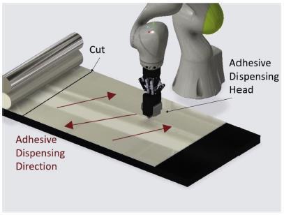
4 Adhesive Dispensing: To bond any prefabricated componentwiththesheetortobondtwoconsecutivesheets, the dispensing of adhesive is required. This is done using an adhesive dispensing head attached to the robot end-effector with the aid of the gripper. An illustration of this step is shown in Fig. 10
5 Bonding: The design of this process is very important for the proper bonding between layers in the sheet laminationbased additive manufacturing system. Three different binding methods could be used: (1) tape bonding, (2) adhesive bonding, and (3) tagging. The selection of the bonding method depends on the layer or the component to be bonded and its application. The tape binding method is used to achieve fast bonding (pressure-sensitive adhesive layer on tape). It works by conforming the tape to the component and bonding it to the sheet by applying pressure with a roller. Adhesive bonding is the most versatile method as it can use pressure-sensitive adhesive or heat-activated resin between sheets and bond them using a roller [19,20,2] The tagging method is used for dry bonding between thin sheets. It is achieved by using a tagging gun to join thin flexible layers together.
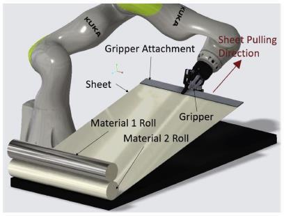
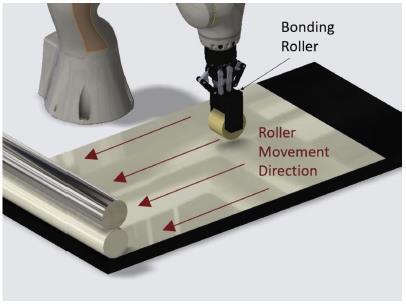
Theprocessstepforcarryingoutadhesivebonding isshown in Fig. 11. The tape binding and tagging steps are not shown for the sake of brevity.
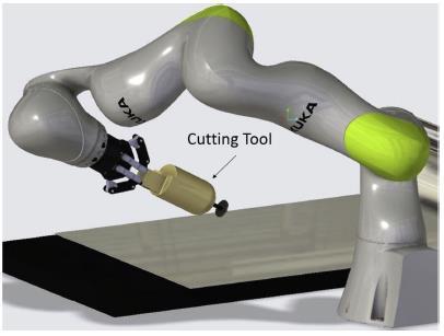
6 Trimming: The trimming step is the final step in the designed system. A variable speed rotary cutting tool or a laser cutting module can be utilized in this step. The illustration for this step is shown in Fig. 12
4.2. Frozen slurry-based laminated object manufacturing
Lack of freezing direction leads to a disorderly porous structure. The freeze-drying-based additive manufacturing can be used to process porous ceramics.
Porousceramicshaveimportantapplicationsinmanyfields, such as filtration, catalyst carrier, thermal insulation, biological medicine, sound absorption, and so on [22,23] Some additive manufacturing (AM) methods can be used to process porous ceramics with complicated shapes, such as three-dimensional printing (3DP), selective laser sintering (SLS), fused deposition modeling (FDM), selective laser gelling (SLG), selective laser burn-out (SLB), and selective laser gasifying of frozen Slurry (FSLG for short). These methods can be used to process parts with bimodal porosity [24,7] A millimeter-scale porosity is processed by controlling the machining path (i.e the pore size depends on the precision of the mechanical control system), and residual μm-level porosity after sintering due to binder reaction/melting solidification or solvent evaporation. However, the processes of binder reaction/meltingsolidification or solvent evaporation are difficult to control, resulting in poor design ability of the micrometer-scale macroporous structure. To improve the design ability of the macroporous structure, the properties of the material must be controlled in the whole process of processing. Through the direct extrusion process (without changing the physical and chemical properties of the material), the ceramic parts with macroporous structure can be obtained by combining the corresponding post-processing technology. Direct ink writing (DIW) takes shear-thinning ceramic ink as the material. [25] It is extruded from the slim-hole nozzle into threadiness, and then the 3D part is constructed through the accumulation of layers. Emulsion/foam templating has the advantages of simplicity and strong applicability to processing porous structures [14]. As a raw material, the emulsion/foam dispersion system with stable rheological performance is used in DIW to process ceramic parts with pore structure. The freeze-drying method uses the sublimation principle of the frozen solvent to obtain a designed porous structure. Porous ceramics with lamellar structure can be obtained by theeze form extrusion fabrication (FEF). Unlike FEF, ceramic/camphene-based slurry is used as raw material in the 3-dimensional ceramic/camphene-based extrusion (3D-Ex) process, the frozen solvent can be sublimated at room temperature. In these freeze drying-based processes, the crystals grow randomly during the freezing process, resulting in a lack of orientation in the lamellar structure. In addition, the extruded slurry filament can easily cause the deformation of the cathe cantilever structure due to gravity. [26,26,27] This study aims to propose a frozen slurry-based laminated object manufacturing (FS-LOM) method, which employed laser cuts in the two-dimensional contour of frozen the furry layer, and freeze-drying to obtain porous structure. [28] The new method enhances the orientation of the lamellar pore structure. Compared with the extrusion process, the deformation of the cantilever structure is avoided.
4.2.1 Materials
The alumina powder (structural material, D50=0.3 μm), carboxymethylcellulose sodium (binder, 1 wt.%), Ammonium polyacrylate (dispersant, 2 wt.%) are mixed thoroughly in the ball mill to prepare a water-based ceramic slurry (alumina content: 50, 55, 60, and 65 wt.%).
4.2.2. Process of FS-LOM
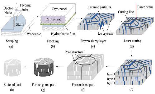
FS-LOM processing includes paving, freezing, cutting, freeze-drying, and sintering, as shown in Fig. 13. The vertical motion worktable is placed in a −20 °C processing environment. [29,30] After the worktable is lowered one layer, the prepared slurry is supplied to the doctor blade through the feeding inlet and scraped on the worktable (Fig. 13a). Then a cryo-panel with an internal circulation of refrigerant is used for freezing. A layer of hydrophobic film was applied to the lower surface of the cryo-panel to avoid the bonding of frozen slurry (Fig. 13b). After the slurry is frozen to the temperature below the eutectic point, the ice crystals are fully grown and the ceramic particles are squeezed together (Fig. 13c); Then the laser gasification is used to incise the outer contours of the 2D pattern (Fig. 13d); The slurry in the region wherethe laser did not scan remains frozen. [31,5] When a new layer is just paved, the micro-ice crystals on the surface of the formerly frozen slurry are melted. After the new layer is frozen, the water produced by the micro-melting is crystallized together with the water in the new layer, and a combination of adjacent layers is achieved. After layers are accumulated, the 3D green part wrapped in the frozen slurry is obtained (Fig. 13e). Then the entire sample is placed in a vacuum freeze dryer (Fig. 13f). After drying is completed, the periphery excess material should be removed, and the ceramic green body is obtained (Fig. 13g). Finally, the ceramic parts with pore structure were obtained after sintering (Fig. 13h).
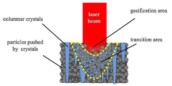
Fig. 14 shows the principle of laser cutting. The CO2 laser is used because the ice has a high absorption coefficient (158,000/m) for a laser with a wavelength of 10.6 μm. The temperature of the materials rises instantly by laser irradiation. When the temperature exceeds the boiling point, the ice crystals and organic additives are gasified directly to form a gasification area, which makes the ceramic particles free from bondage [33,34,6] Some free particles are ejected by the rapidly escaping gas, and the others remain on the scanning line. In the gasification area, some organic additives that have no contact with the air are hightemperature carbonized by laser. [35] With the increase of laser incident depth, the attenuation of energy increases. Below the gasification area, the laser energy is not enough to make the ice crystals gasified, but it can make the ice crystals melt to form a transition area. In the transition area, the ceramic particles are separated from the extrusion of the ice crystals and redistributed in the molten area. Finally, the transition area is refrozen by the surrounding lowtemperature frozen slurry.
[3] Y.Y. Chiu, Y.S. Liao, C.C. Hou, Automatic fabrication for bridged laminated object manufacturing (LOM) process, National Taiwan University, Taipei, Taiwan, Journal of Materials Processing Technology 140 (2019) 179–184.
[4] Tan, H.W., J. An, C.K. Chua and T. Tran, 2019. Metallic nanoparticle inks for 3D printing of electronics. Adv. Electr. Mater. DOI: 10.1002/aelm.201800831.
[5] Walker, K.J. and L.C. Corral, 2017. Exploring the abilities of 3D printing and its viability for consumption in the fashion industry. Apparel Merchandising and Product Development Undergraduate Honors Theses.
[6] 3DExperience, 2018. Directed energy deposition - DED, LENS, EBAM. 3DExperience
[7] Daejeon Ahn, Jin-Hwe Kweon, Jinho Choi, Seokhee Lee, Quantification of surface roughness of parts processed by laminated object Manufacturing, Department of Mechanical Engineering, Pusan National University, Busan 609-735, Republic of Korea, Journal of Materials Processing Technology 212 (2019) 339– 346.
V. CONCLUSION
The introduction part is about the brief history of 3D printing-LOM technology, the next section depicted the processes used in LOM and the properties of the materials. One can conclude that the 3-D printing LOM technology's importance and social impact increase gradually day by day andinfluence human life,theeconomy,andmodernsociety. The recent development in LOM technology could revolutionize the world. Advances in technology can significantly change and improve the way we manufacture products and produce goods worldwide. An object is scanned or designed with Computer-Aided Design software, then sliced up into thin layers, which can then be printed out to form a solid three three-dimensional product. As shown, it can have an application in almost all of the categories of human needs as described by Maslow. While it may not fill an empty unloved heart, it will provide companies and individuals with fast and easy manufacturing in any size or scale limited only by their imagination. 3D printing, on the other hand, can enable fast, reliable, and repeatable means of producing tailor-made products which can still be made inexpensively due to automation of processes and distribution of manufacturing needs.
References
[1] Michael Feygin, Helisys Inc. Brian Hsieh, Helisys Inc. Michel A. Melkanoff, "Laminated Object Manufacturing (LOM): anewtool in theCIM world, Universityof California, Los Angeles.
[2] Bernhard Mueller, Detlef Kochan, Laminated object manufacturing for rapid tooling and patternmaking in the foundry industry, Formguss Dresden, Germany, Computers in Industry 39 _1999. 47
53
[8] Frank van der Klift, Yoichiro Koga, Akira Todoroki, “3D Printing of Continuous Carbon Fibre Reinforced ThermoPlastic (CFRTP) Tensile Test Specimens”, Open Journal of Composite Materials, 2016, 6, 18- 27.
[9] Tan, H.W., J. An, C.K. Chua and T. Tran, 2019. Metallic nanoparticle inks for 3D printing of electronics. Adv. Electr. Mater. DOI: 10.1002/aelm.20180083.
[10] Yamamoto, T., C. Ancely and A. Larnac, 2019. A portrait of DB.
[11] Emirates, 2017. Emirates brings in a step-change in 3D printing for aircraft parts.
[12] Wu, P., J. Wang and X. Wang, 2016. A critical review of the use of 3-D printing in the construction industry. Automat. Constr., 68: 21-31.
[13] Yang, H., W.R. Leow, and X. Chen, 2018. 3D printing of flexible electronic devices. Small Meth., 2: 17002591700259. DOI: 10.1002/smtd.201700259
[14] Siddharth Bhandari, B Regina, “3D Printing and Its Applications”,InternationalJournalofComputerScienceand Information Technology Research ISSN 2348-120X.
[15] Prahar M. Bhatt, Ariyan M. Kabir, Max Peralta, Hugh A. Bruck, Satyandra K. Gupta, A robotic cell for performing sheet lamination-based additive manufacturing, Department of Mechanical Engineering, University of Maryland, College Park, MD 20742, United States, Additive Manufacturing 27 (2019) 278–289.
[16] Geng Zhang, Hua Chen, Shaobin Yang, Yuanzhang Guo, Na Li, Hongwei Zhou, Yan Cao, Frozen slurry-based laminated object manufacturing to fabricate porous ceramic with oriented lamellar structure, School of Mechatronic Engineering, Xi’an Technological University, China, Journal of the European Ceramic Society (2018).
[17] Sreehitha, V., 2017. Impact of 3D printing in automotive industries. Int. J. Mech. Product. Eng., 52: 2092-2320.
[18] M. Dolhen, A. Mahajan, R. Pinho, M.E. Costa, G. Trolliard, P.M. Vilarinho Sodium potassium niobate (K0.5Na0.5NbO3, KNN) thick films by electrophoretic deposition RSC Adv., 5 (2014), pp. 4698-4706, 10.1039/C4RA11058G.

