
3 minute read
International Journal for Research in Applied Science & Engineering Technology (IJRASET)
from Hybrid Power System
by IJRASET


Advertisement

ISSN: 2321-9653; IC Value: 45.98; SJ Impact Factor: 7.538
Volume 11 Issue IV Apr 2023- Available at www.ijraset.com
V. OBJECTIVES
1) Design the hybrid street light equipped with two wind turbines and PV module along with the LED light and pole.
2) Compare different types of wind turbines (VAWT) with different parameters.
3) Identifying suitable Material for the product , also estimating cost for manufacturing our components considering all the factors
4) To find the torque and power generated by hybrid system.
5) To find how extent solar panel will affect the turbine power generation

VI. METHODOLOGY
Our first step is to define the project goals and objectives. Identify the specific requirements for the hybrid power system, such as the power demand, energy storage capacity, renewable energy sources, and the backup system. This step will also involve setting the project scope and defining the project timeline. Next Conduct a site assessment to identify the local conditions, such as the climate, terrain, and available renewable resources. Determine the feasibility of the project and the potential for integrating renewable energy sources into the hybrid power system. This step involves selecting the appropriate renewable energy technologies, such as solar panels, wind turbines, or hydroelectric generators, and the energy storage system, such as batteries or fuel cells. Finally, the hybrid power system's performance should be evaluated regularly to identify anyareas that need improvement. This step involves analyzing the system's efficiency, reliability, and cost-effectiveness and optimizing the system design and operation accordingly, based on the results of the Ansys analysis.
ISSN: 2321-9653; IC Value: 45.98; SJ Impact Factor: 7.538

Volume 11 Issue IV Apr 2023- Available at www.ijraset.com
VII. CAD AND CAE
A. CAD Modeling
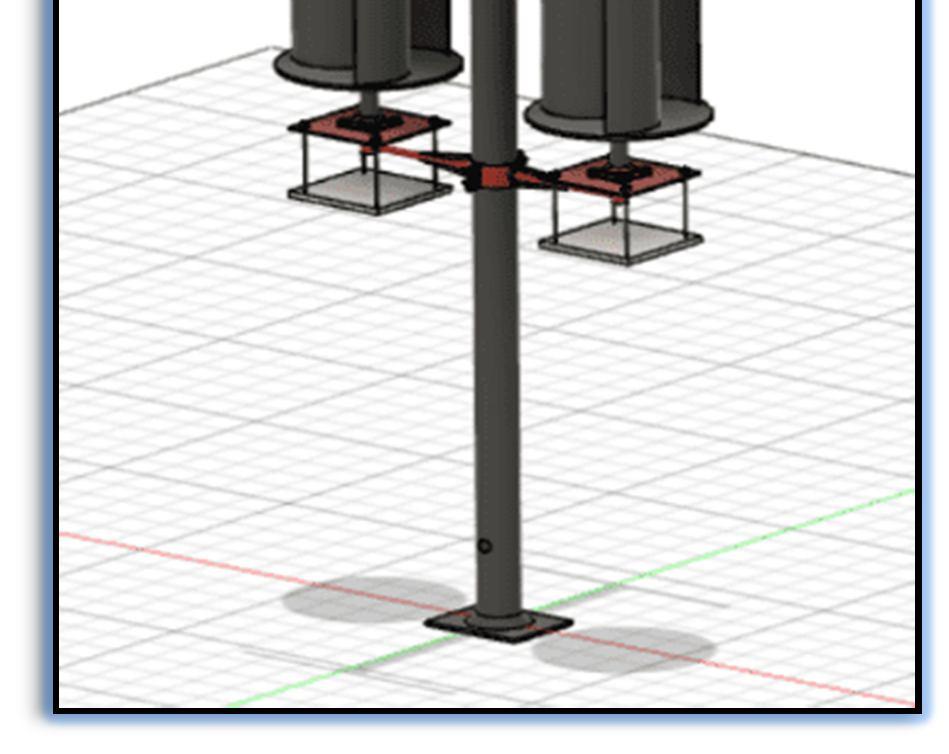
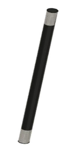
The Hybrid Power System CAD model is developed in Fusion 360 software in a detailed and accurate representation. The model comprises a pole, which acts as a support structure for the entire system, two VAWT Savonius turbines, Solar Panel, and many other small components.

The pole is designed to withstand the weight of the turbines and other components, as well as the wind load on the turbines. It has a circular cross-section and is tapered towards the top, to reduce wind resistance. The pole is modeled with various features such as anchor bolts, flange plates, and brackets, which allow for easy installation and maintenance.
The VAWT Savonius turbines are designed to capture wind energy efficiently, using the principle of drag. The turbines are positioned on opposite sides of the pole to ensure maximum wind capture. The turbines have a curved shape, consisting of two semi-circular blades with a scoop on one side and a flat surface on the other. The blades are designed to rotate in response to the wind, driving the generator to produce electricity. The model also includes the shaft, bearings, and other components necessary for the turbines' operation.
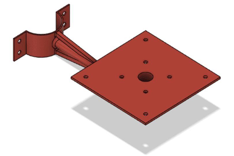
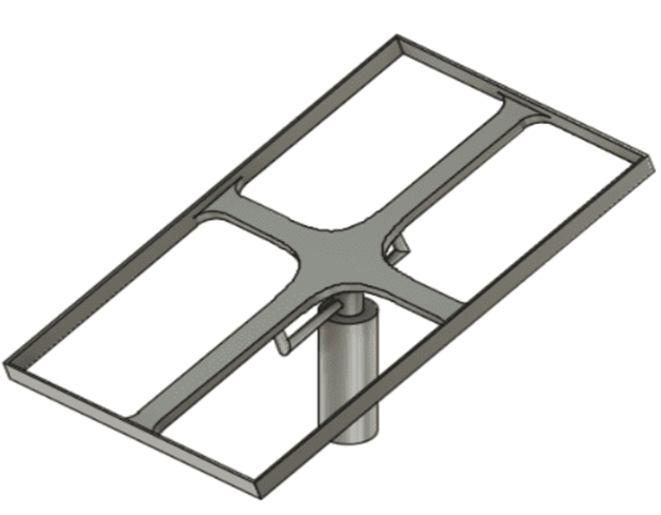
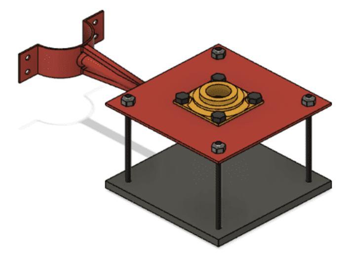
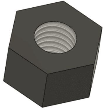
In addition to the pole and turbines, the CAD model also includes many other small components, such as brackets, bolts, and clamps. These components are essential for the system's stability and performance and are accurately modeled to ensure their proper fit and function. Overall, the Hybrid Power System CAD model developed in Fusion 360 software is a highly detailed and accurate representation of the actual system. The model allows for easy visualization and analysis of the system's design and performance, enabling designers and engineers to optimize the system for maximum efficiency and reliability.
1) Components



Journal for Research in Applied Science & Engineering Technology (IJRASET)

ISSN: 2321-9653; IC Value: 45.98; SJ Impact Factor: 7.538
Volume 11 Issue IV Apr 2023- Available at www.ijraset.com
International Journal for Research in Applied Science & Engineering Technology (IJRASET)

ISSN: 2321-9653; IC Value: 45.98; SJ Impact Factor: 7.538
Volume 11 Issue IV Apr 2023- Available at www.ijraset.com
2) Material Analysis

3) Static Stress Simulation
The simulation process involves creating a virtual model of the hybrid power system in the Fusion 360 software and defining the material properties, boundary conditions, and loads that the system will be subjected to. The software then uses finite element analysis (FEA) techniques to solve for the stresses, strains, and displacements in the model. The results of the simulation can be used to identify potential areas of weakness or failure in the system and make design changes to improve its structural integrity. For example, the simulation may reveal that a particular component is experiencing high levels of stress and needs to be redesigned or reinforced to handle the loads. Overall, static stress simulation is a valuable tool for optimizing the design of a hybrid power system and ensuring its reliability and safety.


