2 minute read
International Journal for Research in Applied Science & Engineering Technology (IJRASET)
from Numerical Calculation of Heat Transfer in a Rectangular Channel with Triangular Vortex Generators
by IJRASET

ISSN: 2321-9653; IC Value: 45.98; SJ Impact Factor: 7.538
Advertisement
Volume 11 Issue IV Apr 2023- Available at www.ijraset.com
III. COMPUTATIONAL FLUID DYNAMICS
Computational Fluid Dynamics also generally called CFD is an important branch of fluid mechanics and it uses numerical methods and algorithms to analyze and solve fluid flow problems. It has become popular since the previous methods, experimental and theoretical are either very expensive, time consuming, or involve too much labor. In CFD, computers are used to solve the algorithms that define and analyze the fluid flow. Due to the increase in the computational capabilities over time and better numerical solving methods, most experimental and theoretical work has been done using CFD. CFD is not only cost effective but it helps one analyze and simulate complex geometries, heat transfer, and shock waves in a fluid flow. It also helps solve partial differential equations (PDE) of any order in a fluid flow. CFD mainly helps analyze the internal or external fluid flow. The use of CFD has become increasingly popular in branches of engineering such as Aerospace to study the interaction of the propellers or rotors with aircraft fuselage, Mechanical to obtain temperature distribution of a mixing manifold, Bio-medical engineering to study the respiratory and circulatory systems. There are a few simple generic steps that must be followed for CFD analysis. The following scales and non-dimensional variables are used,
The continuity equation in a non-dimensional form for a steady state flow is given by,
The momentum equation in a non-dimensional form for a steady state flow is given by,
The energy equation in a non-dimensional form for a steady state flow is given by,
ISSN: 2321-9653; IC Value: 45.98; SJ Impact Factor: 7.538

Volume 11 Issue IV Apr 2023- Available at www.ijraset.com
IV. GEOMETRIC MODEL
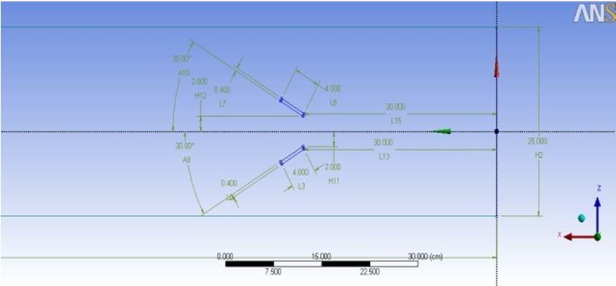
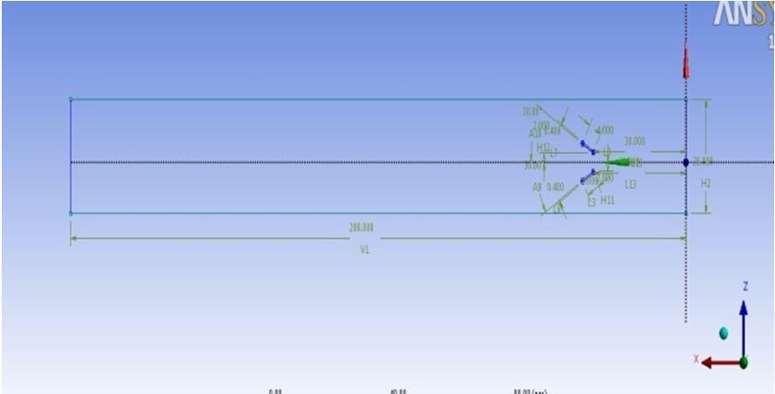
The rectangular channel has cross section dimensions of 25 cm x 10 cm. Length of the channel is 200 cm. The vortex generators have the dimensions length x breadth x height of 1cm x .4 cm x 1 cm. The blade angle for the trangular vortex generators is taken 30°. The bottom wall material is taken as Aluminium and the fluid flowing is water. The flow in the channel is with 3 % turbulent intensity and enters the channel with uniform constant velocity across the cross section. The backflow turbulent intensity at outlet is also taken as 3 %. The Reynolds numbers are chosen as 800, 1200, 1600 and 2000. Shown in Figure 4.2 is the isometric view of the channel along with vortex generators.
A. Grid Generation
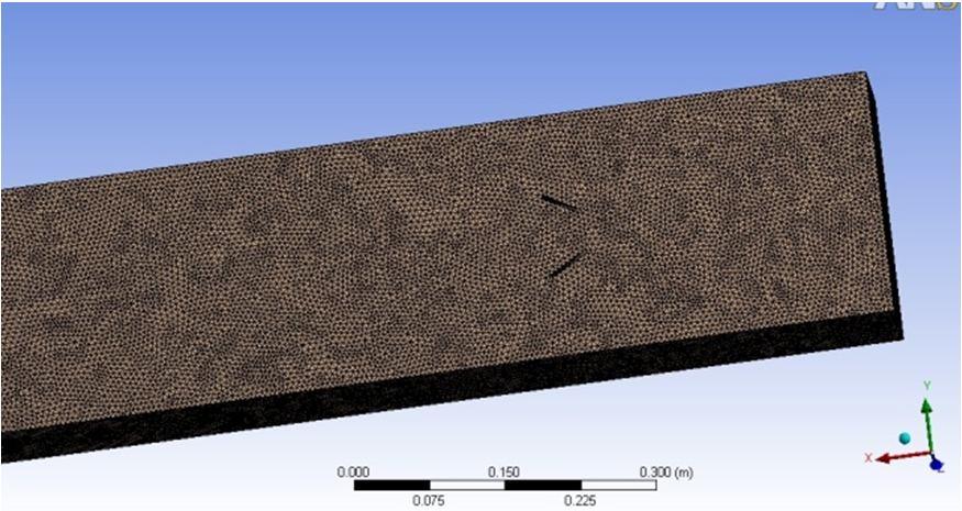
In this study ANSYS Workbench was used as a meshing tool. The structured non uniform grid was generated. The fig. 4.5 shows the fine meshing near the vortex generators. Fine meshing is needed near the wall region to capture the boundary layer on the wall. The whole fluid domain has all the elements as hexa elements. Mapped Face Meshing option from the ANSYS Workbench meshing tool was used to generate this kind of structured non uniform meshing. Bias factor of 10 was used to make the grids near the wall and the vortex generators fine to capture the boundary layer effects

B. FLUENT Setup
FLUENT 14.0 was used for CFD analysis in this study. Importing the mesh files created in ANSYS Workbench, the model is setup to allow energy equation in a Realizable k-Ɛ model with enhanced wall treatment. The fluid in this study is water with a constant density of 998.2 kg/m3, dynamic viscosity of 0.001003 kg/m.s, the constant pressure specific heat is 4182 J/Kg-K, and thermal conductivity is 0.6 W/m.K. The operating condition on the interior of the channel is fluid while the before mentioned boundary conditions are applied on the rectangular channel including the inlet and outlet channel.


