
www.ijtsrd.com e-ISSN: 2456 – 6470
Numerical Simulation of Resistance Spot Welding of Steel Sheets HCT600X+ZF
Cmorej, Ľuboš Kaščák, Julius HajdukABSTRACT
Nowadays, there are so many reasons behind utilizing high-strength steel sheets, more precisely DP (dual-phase) steels in car body production. Car producers tend to choose steel with optimal parameters such as great formability and the capacity to absorb the energyof the collision. HCT600X+ZF steelisamongthebest-known and most-used high-strength materials in car body production. The most used and well-known technologyfor joining high-strengthsteel sheets is precisely the technology of resistance spot welding. RSW (Resistance spot welding), is the well-known method to join mentioned materials. Simulation programs are utilized to optimize the processes of joining before the joining system is carried out. One of the most popular software for simulating the process of RSW is Simufact Welding. The article deals with parameter optimization of RSW (resistance spot welding) for hot-dip zinc-iron-coated dualphase steel sheets. The mechanical properties and metallographic observation of joints created byRSW technologyon galvanizedsteel sheets were performed. The result of the simulation of the RSW process was compared with metallographic images after the joining process.
KEYWORDS: resistance spot welding, optimization, numerical simulation
I. INTRODUCTION
Aspects emphasized in the automotive industry include design, low vehicle weight, good formability, and the abilityto absorbimpact energywithinspecific body parts [1-2].
These aspects have ensured the application of highstrength steel sheets for specific car-body parts [3].
One of the most widelyused high-strength steel is DP (dual-phase) steel. DP steels offer a unique ratio in terms of strength and ductility, due to the specific microstructure of the material, in which the hard martensitic phase is dispersed in the ductile ferritic matrix. DP steels are suitable for the manufacture of safety parts in the automotive industry, such as cross members, longitudinal beams, and reinforcement [46].
RSW (Resistance Spot Welding) is one of the bestknown and most widely used methods for joining high-strength DP steels. RSW is a technology that creates joints without additional material by assisting
How to cite this paper: Denis Cmorej | Luboš Kašcák | Julius Hajduk "Numerical Simulation of Resistance Spot Welding of Steel Sheets HCT600X+ZF" Published in International Journal of Trend in Scientific Research and Development (ijtsrd), ISSN: 2456-6470, Volume-6 | Issue-7, December 2022, pp.983-987, URL: www.ijtsrd.com/papers/ijtsrd52472.pdf
Copyright © 2022 by author (s) and International Journal of Trend in Scientific Research and Development Journal. This is an Open Access article distributedunderthe terms of the Creative Commons Attribution License (CC BY 4.0) (http://creativecommons.org/licenses/by/4.0)
the weldingcurrent with high intensitywhileapplying a clamping force on the electrodes. One of the advantages of mentioned technology is the high intensity of the process as well as the possibility of automating the process. The resulting quality of the joints depends onthe weldingparameters andthetype of material used. The parameters of spot resistance welding include welding time, welding current, and electrode clamping force [7-9].
Simulation software is used to improve the processes of joining/welding beforethe system is applied in real conditions. One of the most used software for simulating the process of RSW is Simufact Welding [10].
The paper deals with the simulation of the process of RSW of HCT600X+ZF steel sheets, and by comparing the results of the simulation with the welded joints that were created.
International
Volume 6 Issue 7, November-December
@ IJTSRD | Unique Paper ID – IJTSRD52472 | Volume – 6 | Issue – 7 | November-December 2022 Page 983
Journal of Trend in Scientific Research and Development (IJTSRD)
2022 Available Online:
Denis
Department of Technology, Materials and Computer-Supported Production, Technical University of Košice, Košice, Slovakia
IJTSRD52472
II. METHODOLOGY OF EXPERIMENTS
USED MATERIALS
One type of material was used in the experiment. The thickness of the tested steel sheets was 1.5 mm. Sheet type HCT600X+ZF is known to be zinc-iron alloycoated (designated as "ZF"), and this coatingprovides better corrosion protection compared to zinc-only coating.
Table 1 shows the basic mechanical properties of the material used. The chemical composition of the steel sheet is shown in Table 2.
BASIC MECHANICAL PROPERTIES OF WELDED MATERIALS
Material (thickness) Rp0.2 [MPa] Rm [MPa] A80 [%] HCT600X+ZF (1.5 mm) 369 633 22.5
CHEMICAL COMPOSITION OF JOINED MATERIALS IN WT [%]
Material (thickness) C Mn P S Cr Mo HCT600X+Z (1.5 mm) 0.08 1.78 0.01 0.006 0.21 0.18
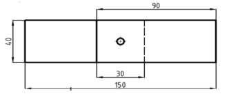
For joints formed by RSW (resistance spot welding), 90x40mm specimens were used with a length of 30mm of overlapping. Dimensions of the samples are defined bySTN 05 1122.Fig. 1 shows thedimensions of the test specimen.
The microscopic analysis of the metallographic cuttings was performed on a KEYENCE VHX-5000 light optical microscope - see. Fig.2.
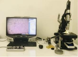
Fig. 1 Test sample
METALLOGRAPHIC OBSERVATION
The change in the microstructure of HCT600X+ZF material, which took place during the formation of joints by RSW resistance spot welding, was analyzed by metallographic observation.
Preparation for metallographic observation included sampling and embedding in dentacrylic, grinding using different grit thicknesses of sandpaper, polishing, and inducing the structure by etching with the application of a 2% nital solution.
Fig 2 KEYENCE VHX-5000
RSW – Resistance Spot Welding
In the experimental part, the joints were formed using a point pneumatic welding machine BPK20. Pneumatic spot welder has adjustable welding parameters and allows the presetting of up to thirty different special welding programs. In the process weldingprocess,weldingelectrodesweremadeofCuCr according to ON 42 3039.71.
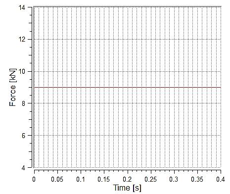
The samples were classified into groups (sample A and sample B) according to the value of the welding current. The welding parameters used for the HCT600X+ZFmaterial are shown in Fig. 3 andTable 4.
Fig. 3 Welding parameter - clamping force of electrodes = 9kN (the same for both groups)
Journal of Trend in Scientific Research and Development
@ IJTSRD | Unique Paper ID – IJTSRD52472 | Volume – 6 | Issue – 7 | November-December 2022 Page 984
International
@ www.ijtsrd.com eISSN: 2456-6470
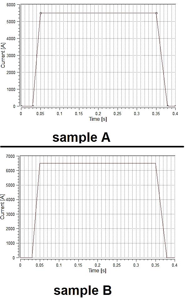
Fig. 4 Welding parameter – welding time and welding current (sample A=welding time= 0.3ms, welding current I=5,5kA; sample B= welding time= 0.3ms, welding current I=6.5kA)
SIMUFACT WELDING SOFTWARE
Simufact Welding software has a utilization for realizing simulations for users working with the welding technology. Simufact Welding enables the use of three-dimensional simulations. Different types of materials specific to the process of welding technology can be simulated. Also, different thicknesses of the materials can be simulated. In practice, simulation software is used to optimize the welding processes before the values of welding parameters are implemented in the process (optimal values are selected).
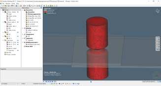
The workplace of the simulation software Simufact Welding is shown in fig. 5.
The software Simufact Welding was used for the optimization of the joining process of resistance spot welding of HCT600X+ZF steel sheets. As part of the optimization of the resistance spot welding process, different values of the welding parameters were compared within the simulations. Based on the recommendations, weldingparameters=thevaluesof the clamping force of the electrodes=9kN; welding time= 0.3ms, and electric current = 5,5kA were used first. When these parameters were used, an optimal connection did not occur. In the place of the weld there was insufficient leakage - see fig. 6. For this reason, it was necessary to optimize the process, implement several other simulations and select the most optimal parameters.
Fig. 5 The workplace of the Simufact Welding software
Fig. 6 Formation of the weld = sample A
It is possible to declare that the optimal welded joint was obtained atthe valuesof the clampingforceofthe electrodes=9kN; welding time= 0.3ms and electric current = 6,5kA – see fig. 7. In the process of the simulation of the process of the welding, the welding electrodes can only be moved in the vertical position, with vertical downward movement.
Fig. 7 Formation of the weld = sample B
International Journal of Trend in Scientific Research and Development @ www.ijtsrd.com eISSN:
@ IJTSRD | Unique Paper ID – IJTSRD52472 | Volume – 6 | Issue – 7 | November-December 2022 Page 985
2456-6470
The joined sheets - a combination of two steel sheets for material HCT600X+ZF were defined as deformable bodies. Welding electrodes were defined as non-deformable bodies.
III. RESULTS AND DISCUSSION
Resistance spot welding models were validated with available experimental results. A simulation RSW model has been developed and extensive numerical calculations were carried out to find out the optimal values of welding parameters such as electric current (electrodes clampingforce and weldingtime werenot changed), resistance spotdiameter, andresidualstress distribution of resistance spot welded HCT600X+ZF joints.
Fig. 8 and Fig. 9 represent a comparison of the crosssections between the real joint created by the resistance spot weldingprocess and the joint resulting from the simulation. Based on the results, real values of the process of resistance spot welding can be compared with values after stimulation. Based on the visual comparison of the obtained results, it can be stated with certain tolerance that the results of resistance spot welding simulations correspond to the result of the actual welding method.
Fig. 9 A comparison of the cross-sections between the real joint created by the resistance spot welding and the welded joint resulting from the simulation = (sample D)
Conclusion
The paper was devoted to the numerical simulation and optimization of the resistance spot welding parameters for HCT600X+ZF steel sheets.
Based on the results of the experiments and based on the realized simulation, it can be stated:
welding of hot-dip galvanized sheets of HCT600X+ZFproduced fusionweldedjoints;the properties which were observed in sample A; a joint was created without pores and cracks, but with insufficient leakage.
welding of hot-dip galvanized sheets of HCT600X+ZFproduced fusion weldedjoints,the best properties were observed in sample B; a joint was created without pores and cracks and with sufficient leakage.
metallographic observation of welded sheets confirmed the importance of a proper choice of welding parameters
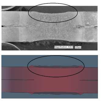

Fig. 8 A comparison of the cross-sections between the real joint created by the resistance spot welding and the welded joint resulting from the simulation = (sample A)
based on the visual comparison of the obtained results, it is possible to confirm with certain tolerance that the results after the simulation correspond to the result of the actual resistance spot welding process.
International Journal of Trend in Scientific Research and Development @ www.ijtsrd.com eISSN: 2456-6470 @ IJTSRD | Unique Paper ID – IJTSRD52472 | Volume – 6 | Issue – 7 | November-December 2022 Page 986
Acknowledgment
The authors are grateful for the support of experimentalworksbyprojectAPVVSK-PL-21-0033 “Research into innovative forming and joining methods of thin-walled components” and project APVV-21-0418“Developmentofinnovativemethods of processing and joining electrical steels for highefficiency applications in e-mobility”.
References
[1] Ľ. Kaščák, et al.; Applicationofmodernjoining methods in car production.ProcessesExamples Strength. Rzeszów, pp. 143, ISBN978-80-5330820-3, 2013
[2] A. Vita et al.; Comparative life cycle assessment of low-pressure RTM,compression RTM and high-pressure RTM manufacturing processes to produce CFRPcarhoods.Procedia CIRP. Volume 80, pp. 352-357, 2019
[3] D. Cmorej et al.; Analýza spájania mikrolegovanej ocele HX420LAD, vol. 41,pp. 352-35, 2019
[4] S. Qin et al.; Influence of phase and interface properties on the stress state dependent fracture initiation behavior in DP steels through computational modeling.MaterialsScience and Engineering:A. Vol. 776,138981, 2020
[5] Ľ. Kaščák, and J. Viňáš, “Influence of welding parameters of resistance spot welding on the
www.ijtsrd.com eISSN: 2456-6470
quality of welded joints,” Scientific Papers of University of Rzeszow: Zeszyty Naukowe Politechniki Rzeszowskiej, vol. 273, pp. 127134, 2010
[6] K. Bzowski et al.; Application of statistical representation of the microstructure to modeling of phase transformations in DP steels by the solution of the diffusion equation. Procedia Manufacturing. Vol. 15, pp. 18471855, 2018
[7] H. Zhang, and J. Senkara, “Resistancewelding: Fundamentals and Applications,” New York: Taylor & Francis, 2006.
[8] P.S. Wei, and T.H. Wu, “Electrical contact resistance effect on resistance spot welding,” International Journal of Heat and Mass Transfer, vol. 55, pp. 3316-3324, 2012.
[9] H. B. Hernandez, S. K. Panda, Y. Okita, and N. Y. Zhou, “A study on heat affected zone softening in resistance spot welded dual phase steel by nanoindentation,” Journal of Materials Science, vol. 45, pp. 1638–1647, 2010.
[10] U. Shah et al.; Computational analysis of the ultrasonic effects on resistance spot welding process. Journal of Manufacturing Processes, vol. 81, pp. 191-201, 2022.
@ IJTSRD | Unique Paper ID – IJTSRD52472 | Volume – 6 | Issue – 7 | November-December 2022 Page 987
International Journal of Trend in Scientific Research and Development @