
Electric Vehicle Driven by Solar PV Batteries and Regenerative Brakes via a Zeta Converter
1Student, 2Assistant Professor, 3Associate Professor, 1, 2, 3Oriental Institute of Science & Technology, Bhopal, Madhya Pradesh, India
This paper proposes a unique regenerativebrakingmethodbasedona Brushless DC (BLDC) motor. Braking may be accomplished using the suggested technique by applying a varied Stator voltage from a multi-cell battery system DC-DC buck converter. A simulation was utilised to testthe performance of the suggested brakingmechanism. The suggested regenerative braking technology is viable and efficient, according to simulation findings. Furthermore, this study presents the most basic technologyfor regenerative brakingutilising a BLDC motor to increase the mileage of lightweight electric cars (EVs).
KEYWORDS: Solar PV, Electric Vehicle, Regenerative Braking, Zeta Converter, P&O - MPPT, Battery & PMBLDC
How to cite this paper: Akansha Sneha | Neeti Dugaya | Dr. Geetam Richhariya | Dr. Manju Gupta "Electric Vehicle Driven by Solar PV Batteries and Regenerative Brakes via a Zeta Converter" Published in International Journal of Trend in Scientific Research and Development (ijtsrd), ISSN:24566470, Volume-6 | Issue-7, December 2022, pp.11911198, URL: www.ijtsrd.com/papers/ijtsrd52591.pdf
Copyright © 2022 by author (s) and International Journal of Trend in Scientific Research and Development Journal. This is an Open Access article distributed under the terms of the Creative Commons Attribution License (CC BY 4.0) (http://creativecommons.org/licenses/by/4.0)
I. INTRODUCTION
The grave environmental risksassociatedwithcarbon emissions and the divestment of fossil fuels need the development of alternate or renewable energy sources. The transition from internal combustion engines to electric vehicles is a big step forward for humanity toward the goal of zero carbon emissions and sustainable development. Because of its simpler control algorithm than other EV motors, the PMBLDC motor has found widespread usage in light electric vehicle sectors such as e-rickshaws and twowheelers. Energyis easilyregenerated inaPMBLDC motor and stored in the batteryduringdeacceleration.
Electrical braking is not usually effective below a specific vehicle speed, and energy cannot be recovered during emergency brakes. The compatibilityof electronicandmechanicalbrakes[1]. The quantityof regenerationachievableisdetermined on the amount of brake pressure applied to the throttle, as shown in [2]. [3] has a fuzzy logic-based control system that significantly increases braking performance. Because sliding mode control offers
high steady-state performance, it eliminates undesirable oscillations in the DC bus while moving between driving and braking modes [4]. A bidirectional DC-DC converter is used in [5] to maintain DC bus voltage and reverse power flow while braking. For optimal battery charging, the motor's back emf must remain constant [6].
Findingthe zero-crossings of the back emf [7] isused to determine rotor location. The rotor location is also approximated more accurately by analysing the inverter switchingfunction [8]. Thirdharmonicstator voltage waveformprovidesrotorpositioninformation and may be utilised to produce sensor less methodology.
The zeta converter is used to extract the most power from the solar panel while also providingdependable dynamic performance across a broad range of climatic circumstances. WhencomparedtootherDCDC converters, the Zeta converter has the following distinct benefits in solar-PV-based applications,
International
Volume 6 Issue 7, November-December
Available
@ IJTSRD | Unique Paper ID – IJTSRD52591 | Volume – 6 | Issue – 7 | November-December 2022 Page 1191
Journal of Trend in Scientific Research and Development (IJTSRD)
2022
Online: www.ijtsrd.com e-ISSN: 2456 – 6470
Akansha Sneha1 , Neeti Dugaya2 , Dr. Geetam Richhariya3 , Dr. Manju Gupta3
IJTSRD52591
Because it functions in buck-boost mode, it can handle a broad variety of MPPTs under dynamic conditions. [12]. A simple buck or boost converter has a maximum duty ratio that corresponds to a certain mode of operation.
The zeta converter's output inductor guarantees that there is no ripple current at the output of the boost or buck-boost converter [13].
Unlike the Cuk converter, which has both input and output ripple free current, the zeta converter has noninverted output polarity. As a result, the necessityfor negativevoltagesensingisremoved, lowering the complexity of sensor circuits. [14].
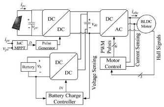
Figure 1 depicts the solar-PV array and batterypowered PMBLDC motor drive. A bidirectional DCDC converter connects the battery to the DC connection, increasing the cost and weight. The bidirectional DC-DC converter maintains the DC connection voltage and ultimately controls battery charging and discharging. At the front end of MPPT, a DC-DC power converter is employed. For speed control, two voltage sensors and two current sensors are needed, as well as hall sensors for position feedback. A Z-source DC-DC converter replaces the dc-dc converter in [15].However,controllingthissort of DC-DC converter involvessomeadvancedcontrol, such as monitoring phase currents and dc link voltage.
The following is how the paper is organised. The system is described in Section II. The design processes are presented in Section III. Section IV discusses the control measures utilised, followed by the findings in Section V and the conclusion in Section VI.
zeta converter, a three-phase voltage source inverter (VSI), and a PMBLDC motor. As a result of the battery being attached to the system DC bus, the proposed solution removes the requirement for a second power converter and significantly decreases the number of sensors utilised. In the suggested system, just two voltage sensors are needed to accomplish MPPT and sensor less control.
Fig 1 Conventional SPV battery-fed BLDC drive II. SYSTEM DESCRIPTION AND OPERATION
Figure 2 depicts the construction of the proposed solar-PV and battery-powered PMBLDC motordriven electric vehicle system with a zeta converter. The vehicle's powertrain consists of a solar panel, a
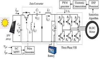
Fig.2. Proposed System Schematic
The motor requires electrical power, which is supplied by both the battery and the solar-PV panel. A zeta converter transfers the maximum power collected from the solar panel to the VSI. For MPPT operation, an incremental conductance algorithm is applied. The whole electrical power from the DC bus is sent to the load through the VSI and the intermediating zeta converter. A pulse generator generates switching pulses for the zeta converter using the In C-MPPT algorithm, which adjusts the duty ratio to run the converter at maximum power. The calculated duty ratio is then compared to a high frequency carrier signal to ensure optimal switching efficiency to the converter at the highest ideal power point. The switchingof the VSI's IGBTs is controlled by the PMBLDC motor's electronic commutation logic. Switching losses are reduced since the VSI is switched at the fundamental frequency. Furthermore, energyregenerationisdonebi-directionallyfromboth sources to load. The VSI is now acting as a rectifier and charging the battery. It is also possible to establish position sensor-less control for electronic commutation of the PMBLDC motor,whichremoves the requirement for mechanical Hall sensors and the complicated electric circuitry associated with them.
III. DESIGN OF PROPOSED SYSTEM
Different power stages of the proposedEVdrivetrain, as shown in Fig. 2, are intended to be designed for maximum efficiency and flawless operation regardless of weatherconditions.A800-WPMBLDC motor is used to power the vehicle, which is powered by a solar-PV array with a peak power rating of 326W and a 48-V, 80-Ah Li-ion battery. The complete design method is provided in detail below.
@ IJTSRD | Unique Paper ID – IJTSRD52591 | Volume – 6 | Issue – 7 | November-December 2022 Page 1192
International Journal of Trend in Scientific Research and Development @ www.ijtsrd.com eISSN: 2456-6470
A. Design of Solar PV Panel and MPPT
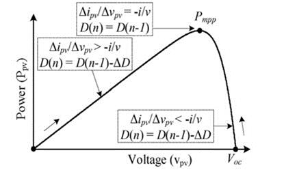
As illustrated in Fig. 3, a solar photovoltaic panel is intended to operate in MPPT mode. The InC MPPT algorithm is employed withfasttrackingperformance and reduced error among the different control methods accessible in the literature. The zeta converter is used to regulate maximum power. When the differential incremental conductance (ipv/vpv) matches the actual conductance (ipv/vpv), this is the ideal operatingpoint.Thedetermineddutycyclefrom the implemented method allows the Zeta converter to readily monitor MPPT.
Given a complete solar insolation of 1000W/m2, the maximum power from a solar panel is set at 326W. The PV specifications are designed with a 60V open circuit voltage and an 8.3A short circuit current. The optimal operating point has been determined to be 0.75 times the open circuit voltage and 0.9 times the maximum short circuit current rating. As a result, the voltage and current ratings are Vmp = 60*0.70 V = 42 V and Imp = 326/42 A= 7.76 A.
TABLE I. SPECIFICATIONS OF SOLAR-PV ARRAY
Maximum power, Pmp (W) 326
Voltage at open circuit, Voc (V) 60
Voltage at max power point, Vmp (V) 42
Current at short circuit, Isc (A) 8.3
Current at max power point, Imp (A) 7.76
B. Design of Zeta Converter
The 350 W solar panel must be kept in MPPT mode. At MPP, the voltage of the solar panel, Vpv = Vmp = 60V, and the current, Ipv = Imp =7.76 A. The duty ratio of the zeta converter is determined to be,
V c denotes the average DC capacitor voltage.
The motor requires 800W of electricity, which must be supplied by the solar panel and batteries. As a result, the power at the DC link is 800 W, and the capacitor current that passes over the bus is predicted to be, Table II shows the complete design methods, including design equations and final data, with all symbols having clearmeanings.Thedesignequations for the converter's continuous conduction mode (CCM) operation are calculated, reducing switching pressures on the components.
Fig. 3. InC-MPPT algorithm
TABLE II DESIGN OF ZETA CONVERTER
Parameter Expression Design Data Value
Research
@ IJTSRD | Unique Paper ID – IJTSRD52591 | Volume – 6 | Issue – 7 | November-December 2022 Page 1193
International Journal of Trend in Scientific
and Development @ www.ijtsrd.com eISSN: 2456-6470
IV. CONTROL STRATEGY OF PROPOSED SYSTEM
The suggested drive system's control is divided into two parts: MPPT control in the front-end converter and load-end VSIcontrolforoptimalmotorelectronic commutation during driving and regenerative mode. The MPPT control approach has previously been discussed in the preceding section. As a result, the sensor less electronic commutation approach of the PMBLDC motor with regenerative braking feature is thoroughly examined here.
A. Electronic Commutation
The PMBLDC motor's six-step electronic commutation is accomplished bycorrectswitchingof the VSI in 120-degree mode of operation utilising three virtual Hall sensor signals created bythe sensor less control algorithm. Each 60-degree step has two power switches active at the same time. As a result, during each commutation interval, two phases of the motor are activated while the other phase stays mute.
DuVSI is used as a single-phase rectifier in PWM mode to charge the battery during ring regenerative braking. Table IIIshows the VSIswitchingprocedure for both types of operation.
TABLE
III
SWITCHING STATES OF THE VSI
Where θ is the electrical rotor angle. The sum of the three backemf equations is expressed as, Again, the total of the PMBLDC motor's three phase voltages is used,
B. Sensor less Control Topology
The third harmonic stator flux is employed here to providepositionsensor-lesselectricalcommutationof the motor. The backemfs of the motor are used to calculate the third harmonic flux. The fourier series representation of the three phase backemfs is as follows,
As in steady state, can be approximated as,
As a result of (4) and (6), it is possible to conclude that information about the third harmonic component of backemf is encoded in the sum of three phase voltages.
Now third harmonic stator flux can be obtained as, dt (7)
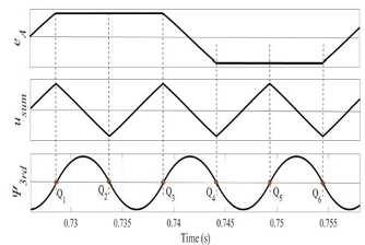
As illustrated in Fig. 4, the generated third harmonic stator flux linkage from the integration of the u sum may be utilised to estimate the location of the rotor since the zero-crossing points of _3rd are the precise commutation points.
Fig 4 Relationship among backemf and stator flux and zero-crossings
International Journal of Trend in Scientific Research and Development @ www.ijtsrd.com eISSN: 2456-6470 @ IJTSRD | Unique Paper ID – IJTSRD52591 | Volume – 6 | Issue – 7 | November-December 2022 Page 1194
Steps Mode 0º60º 60º120º 120º180º 180º240º 240º300º 300º360º Motor S1 S4 S1 S6 S3 S6 S3 S2 S5 S2 S5 S4 Regen. S3. S2 S5. S2 S5. S4 S1. S4 S1. S6 S3. S6
C. Elimination of false zero-crossings
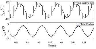
The terminal voltage of the motor is used tocreatethe three backemf signals. In Fig. 5, the detectedterminal voltages have undesired spikes. This causes spurious zero crossings and causes the whole switching logic of the VSI to fail. A first order lowpass filter is intended to eliminate those pesky spikes.
The cut off frequencymust be carefullychosen while creating the filter. Taking phase lag into account, the cut off frequency in this study is set at 1000 rad/s. The lowpass filter's transfer function is,
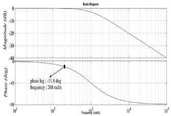
(8)
The LPF adds some phase lag to the system. The phase lag in relation to the speed of the PMBLDC motor may be calculated as,
increases, which mayresultinsignificantlossesinthe motor winding. As a result, a compensator with a leading phase angle is required to compensate for the added lag.
The lead compensator in this work is meant to correct for a phase lag of -11.8o at a frequencyof 208.4 rad/s while the motor is operating at 1200 rpm. The compensator transferfunctionisexpressedasfollows,
Where k is the magnitude constant and c1 and c2 are the zero and pole crossover frequencies, respectively. The predicted value of k is,
Where the angular frequency of the derived backemf is denoted by. The phase lag induced by the LPF while running at 1200 rpm is -11.7o, as illustrated in Fig 6.
The time constant T is, So, the cut off frequencies are estimated as,
Fig 5 Unfiltered and filtered line voltage waveform
So, the transfer function becomes,
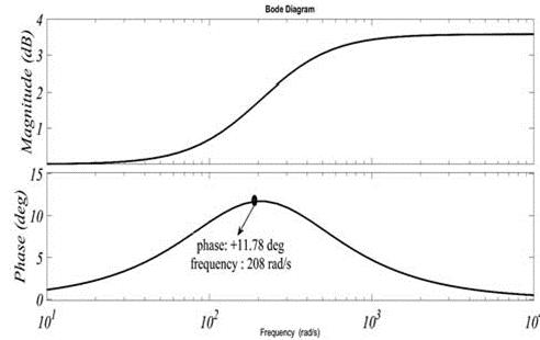
Figure 7 shows the Bode plot for the aforementioned system. A phase lead of 11.8o is successfully obtained at frequency 208 rad/s. The filtered waveform of the terminal voltage is presented in Fig. 5, where all undesirable spikes have been eliminated by filtering. The commutation error of the PMBLDC motor may be greatly reduced by using these filtered and corrected waveforms.
Fig 6 Bode plot diagram for lag compensator
D. Design Procedures of Lead Compensator
At higher speeds, the phase lag caused by the low pass filter creates errors in predicting the zerocrossing sites. Furthermore, the torque ripple
Fig 7 Bode plot diagram for lead compensator
International Journal of
in Scientific Research and Development
@ IJTSRD | Unique Paper ID – IJTSRD52591 | Volume – 6 | Issue – 7 | November-December 2022 Page 1195
Trend
@ www.ijtsrd.com eISSN: 2456-6470
International Journal of Trend in Scientific Research and Development @ www.ijtsrd.com eISSN: 2456-6470
V. RESULTS AND DISCUSSION
The whole EV model is simulated in MATLAB, and the comprehensive simulation results and comments are shown below. To evaluate the performance of a solar PV battery-fed electric vehicle with regenerative braking using a zeta converter.
Performance of solar PV array
Performance of Zeta Converter
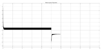
Performance of PMBLDC motor
Figure 8: Simulink Model of a PV battery-powered EV system with regenerative braking using a zeta converter.
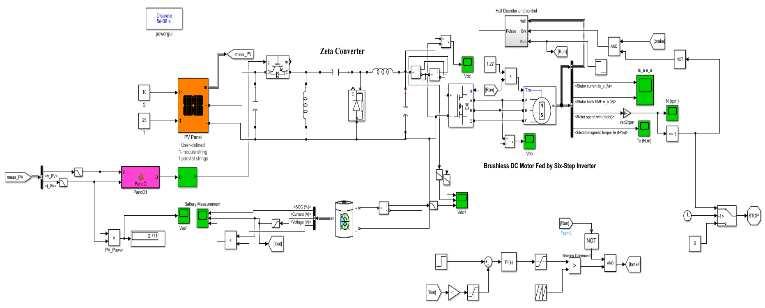
Figure 9. DC Bus Voltage Vs Time

Figure 11. Line – Line Voltage (Vab) Vs Time
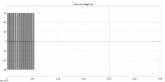
Figure 10. Electromagnetic Torque (NM) Vs Time
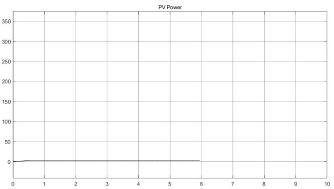
Figure 12. PV Power Vs Time
@ IJTSRD | Unique Paper ID – IJTSRD52591 | Volume – 6 | Issue – 7 | November-December 2022 Page 1196
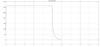
Figure 13. Rotor Speed (RPM) Vs Time
range and less phase delay. Appropriate phase compensators are developed to reduce commutation error in sensorless operation. Negative voltages are simpler to detect at the output of a noninverting zeta converter, allowing for more control flexibility. Because the zeta converter outputs constant current, no additional filters or interface inductors are required. The proposed PMBLDC motor drive for EVs is low-cost, reliable, and simple to instal in realworld applications.
REFERENCES
[1] Valentin Totev; Vultchan Gueorgiev “Efficiencyof RegenerativeBrakinginElectric Vehicles” 2020 21st International Symposium on Electrical Apparatus & Technologies (SIELA).
Figure 14. SOC %, Battery Current and Battery Power Vs Time

[2] Abhishek Gaurav; Anurag Gaur “Modelling of Hybrid Electric Vehicle Charger and Study the Simulation Results” 2020 International Conference on Emerging FrontiersinElectrical and Electronic Technologies (ICEFEET).
[3] Dragos Niculae; Mihai Iordache; Marilena Stanculescu; Maria Lavinia Bobaru; Sorin Deleanu “A Review of Electric Vehicles Charging Technologies Stationary and Dynamic” 2019 11th International Symposium on Advanced Topics in Electrical Engineering (ATEE).
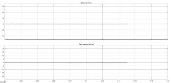
Figure 15. Stator Current Ia and Electromotive Force Ea Vs Time
[4] Ahad Javandoust Qarebagh; Farnaz Sabahi; Dariush “NazarpourOptimized Scheduling for SolvingPositionAllocationProbleminElectric Vehicle Charging Stations” 2019 27th Iranian Conference on Electrical Engineering (ICEE).
[5] Junbeom Wi; Hyunhwa Kim; Jiho Yoo; Hanho Son; Hyunsoo Kim; Byungjae Kim “Energy consumption of parallel type hybrid electric vehicle with continuouslyvariabletransmission using electric oil pump” 2018 Thirteenth International Conference on Ecological Vehicles and Renewable Energies (EVER).
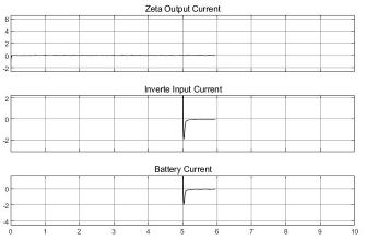
Figure 16. Zeta Converter Output Current, Inverter Input Current and Battery Current Vs Time
VI. CONCLUSION
We discuss and investigate a position sensor-less PMBLDC motor-driven EV system that employs a zeta converter for maximum power point tracking control with regenerative braking in this study. The rotor's position is determined by taking the third harmonic of the stator flux. When compared to the usual backemf technique, this one has a wider speed
[6] Chaoqun Liu; Bin Wei; Songcen Wang; XiaokangWu; Xian Zhang; Jie Wang; Qingxin Yang “Field Circuit Coupling Analysis of Dynamic Wireless Charging for Electric Vehicle” 2018 IEEE 2nd International Electrical and Energy Conference (CIEEC).
[7] Jing Zhang; Hui Yan; Ning Ding; Jian Zhang; Taoyong Li; ShuSu“ElectricVehicleCharging Network Development Characteristics and Policy Suggestions” 2018 International Symposium on Computer, Consumer and Control (IS3C).
International Journal of Trend in Scientific Research and
@ IJTSRD | Unique Paper ID – IJTSRD52591 | Volume – 6 | Issue – 7 | November-December 2022 Page 1197
Development @ www.ijtsrd.com eISSN: 2456-6470
International Journal of Trend in Scientific Research and Development @ www.ijtsrd.com eISSN: 2456-6470
[8] Araz Saleki; Saman Rezazade; Mahmudreza Changizian “Analysis and simulation of hybrid electric vehicles for sedan vehicle” 2017 Iranian Conference on Electrical Engineering (ICEE).
[9] V. P. Dhote; M. M. Lokhande; AkashAgrawal; B. Hemanth Kumar “Mechanical coupling of two induction motor drives for the applications of an electric-drive vehicle system” 2017 National Power Electronics Conference (NPEC).
[10] Oliver Marcincin; Zdenek Medvec; Petr Moldrik “The impact of electric vehicles on distribution network” 2017 18th International Scientific Conference on Electric Power Engineering (EPE).
[11] Fatemeh Jozi; Kazem Mazlumi; Hadi Hosseini “Charging and discharging coordination of electric vehicles in a parkinglotconsideringthe limitation of power exchange with the distribution system” 2017 IEEE 4th International Conference on Knowledge-Based Engineering and Innovation (KBEI).
[12] Egor Kulik; Xuan Trung Tran; Alecksey Anuchin; Yuriy Vagapov “GPS-track data processing for the optimization of the powertrain for hybrid electric vehicles” 2017 IEEE 58th International Scientific Conference
on Power and Electrical Engineering of Riga Technical University (RTUCON).
[13] Somayyeh Khatiri-Doost; Meysam Amirahmadi “Peak shaving and power losses minimization by coordination of plug-in electric vehicles charging and discharging in smart grids” 2017 IEEE International Conference on Environment and Electrical Engineering and 2017 IEEE Industrial and Commercial Power Systems Europe (EEEIC / I&CPS Europe).
[14] X. D. Xue; K. W. E. Cheng; S Raghu Raman; Jones Chan; J. Mei; C. D. Xu “Performance prediction of light electric vehicles powered by body-integrated super-capacitors” 2016 International Conference on ElectricalSystems for Aircraft, Railway, Ship Propulsion and Road Vehicles & International Transportation Electrification Conference (ESARS-ITEC).
[15] Muhammad Sifatul Alam Chowdhury; Khandakar Abdulla Al Mamun; Al Mahmudur Rahman” Modelling and simulation of power system of battery, solar and fuel cell powered Hybrid Electric vehicle” 2016 3rd International Conference on Electrical Engineering and Information Communication Technology (ICEEICT).
@ IJTSRD | Unique Paper ID – IJTSRD52591 | Volume – 6 | Issue – 7 | November-December 2022 Page 1198