
www.ijtsrd.com e-ISSN: 2456 – 6470
Design and Development of a Low Cost Handheld Vacuum Cleaner
1Professor, Department of Mechanical Engineering, 2Research Scholar, 1,2Velalar College of Engineering and Technology, Erode, Tamil Nadu, India
ABSTRACT
A vacuum cleaner, like many other home products, is made to use it easier and more efficient for its customers to complete particular tasks. It must be effective at both collecting up dust particles and eliminating them from the air. This research paper develops a low cost effective vacuum cleaner and its parts. According to the literature review, the vacuum cleaner’s performance is mostly influencedbyparameters includingtheimpeller’sdiameter,radiusof curvature, strength, and speed. In this study, an unique impeller is designed with Creo, and the flow characteristics of the impeller are examinedusingCFD.Theimpeller’sthickness,form,andnumberof blades are all determined using the mechanical design process. In addition,polycarbonatewasusedasamaterialformakingimpellerin 3D printing.
KEYWORDS: Vacuumcleaner,Impeller,CFDAnalysis,3DPrinting
How to cite this paper: Dr. Velumani Subramaniam | Bhuvanesh Kumar V | MidunK |MohanprasathG"Designand Development of a Low Cost Handheld Vacuum Cleaner" Published in International Journal of Trend in Scientific Research and Development (ijtsrd), ISSN: 2456-6470, Volume-6 | Issue-7, December 2022, pp.639-644, URL: www.ijtsrd.com/papers/ijtsrd52404.pdf
Copyright © 2022 by author (s) and International Journal of Trend in Scientific Research and Development Journal. This is an Open Access article distributed under the terms of the Creative Commons Attribution License (CC BY 4.0) (http://creativecommons.org/licenses/by/4.0)
1. INTRODUCTION
Avacuumcleaner, likemanyotherhomeproducts, is made to use it easier and more efficient for its user to complete particular tasks. A vacuum cleaner collects different types of debris, dust, allergies, etc. byusing air flow, which is frequently paired with brushing action. Itmustbeeffectiveatbothcollectingupthese things and eliminating them from the air in order to prevent them from being re-circulated back into the living space. It can be challenging to identify which profile of the impeller of the vacuum cleaner will actually perform the best.
Themost crucial component ofmodern livingis time management. In industries and houses, cleaning is one of the most tedious and demanding tasks. An electromechanicaltoolfrequentlyusedtoeasilyclean them is avacuum cleaner. Cleaningbecomes quicker and easier as a result. The vacuum cleaner has an electric motor that rotates the impeller to partially produce a vacuum and suck outside air into the suction chamber. So that the dust and debris close to the vacuum cleaner’s nozzle are drawn within the vacuum cleaner. A filter is used to remove dust and
grime from the air and they are then kept in storage section.
Methodology for System-Level Analysis of a FanMotorDesignforaVacuumCleanerwassummarized by Park et al. 2017. Optimization of the Flow Path Efficiency in a Vacuum Cleaner Fan was given by Son et al. 2018 and they have calculated the fan motor unit for a compact vacuum cleaner and achieved a 30% smaller than a full-size one.
Ashish J. Patel 2015 have investigated Design and Flow through CFD Analysis of Enclosed Impellers and reported the significance of the impeller design. Effect of Blade Number on Characteristics of Centrifugal Pumps was demonstrated by “Effects of bladenumberoncharacteristicsofcentrifugalpumps” 2010. The study examined how a centrifugal pump’s performance is impacted by the number of impeller blades. Three distinct impellers with 5, 7, and 9 blades are numerically tested at a rotating speed of 2800 rpm to identify the ideal number of blades.
Volume
@ IJTSRD | Unique Paper ID – IJTSRD52404 | Volume – 6 | Issue – 7 | November-December 2022 Page 639
International Journal of Trend in Scientific Research and Development (IJTSRD)
6 Issue 7, November-December 2022 Available Online:
Dr. Velumani Subramaniam1, Bhuvanesh Kumar V2, Midun K2, Mohanprasath G2
IJTSRD52404
Gajbhiye,Ahmad,andTufail2018havedesignedand createdapplicationsofaD.C.VacuumCleanerUsing Axial Flow Fan and the paper served as the inspiration for the design and construction of the vacuum cleaner. Bacharoudis et al. 2008 have done the Parametric study of a Centrifugal Pump Impeller byVaryingtheOutlet BladeAngle.Thesimulationof a pump’s performance in terms of the impeller outlet diameter, blade angle, and number were dealt in the study. Bhosale and Gore 2017 in their Review article Paperhavefound ImprovementofImpellerDesignof a Centrifugal Pump Using FEM and CFD. The paper expressed the centrifugal pump’s efficiency and energy which was influenced by a number of factors such as material, blade angle, and blade count. Therefore,itisessentialforthegrowthoftheimpulse in order to increase the pump’s effectiveness.
Khelladietal.2005havereportedanewdesignofthe impeller-diffuser interface of a vaned centrifugal fan in this paper, theoretical and experimental work on unsteadythree-dimensional(3D)flowshasbeendone in order to better understanding the fluid flow behaviour in vane centrifugal fans.
From the literature survey it is understood that the primary variables affecting the performance of the vacuumcleaneraretheimpeller’sdiameter,radiusof curvature, strength, and speed. The performance of the vacuum cleaner changes when the impeller size and shape are altered. A new impeller is necessary to enhance the performance of portable light weight vacuum cleaners.
2. PRINCIPLE OF VACUUM CLEANER
The fundamental working principle of a vacuum cleaner is that materials flow when there is a pressure difference between two points. Anelectricmotorrotates thecentrifugalimpeller. Negative pressure is produced on one side of the impellerasaresultoftheimpellerrotating.Soair isdrawnintotheothersideofthevacuumcleaner and forced into it. Any dirt and dust particles present nearbyalso will be sucked along with the air.
Thevacuumcleanerunithasafunctionofsuction and discharge, and a filter and storage compartmentarelinkedonthesuctionside.Airis filtered to remove dust and grains, finally the air is sent out to the atmosphere.
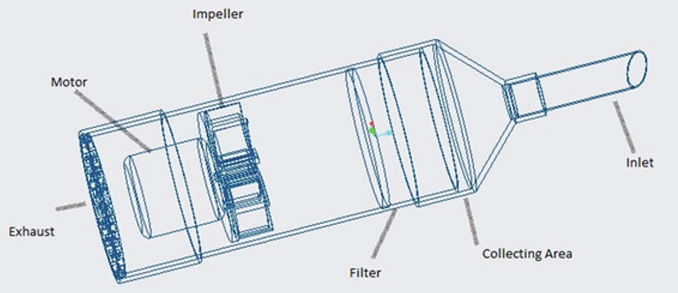
3. COMPONENTS DESCRIPTION
Thecomponents that are used in theprototypemodel are as follows, also illustrated in the diagram fig 1. Impeller Motor Filter
Collecting area
Inlet
Mini 2 pin SPST switch
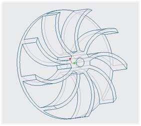
3.1. IMPELLER
Avacuumcleaner’simpellergeneratesactualsuction. It is a disc-shaped device with blades that are always positioned directly on the suction motor’s shaft, causing it to rotate rapidly and is shown in fig 2. Suctionisproducedbytheeffectsofcentrifugalforce on the revolving air inside the impeller. A partial vacuum is created as the impeller rotates, which causes the rotating air to move away from the core and allow more air to flow into the vacuum cleaner. The primary variables determining the performance of the vacuum cleaner include the impeller’s diameter, radius of curvature, strength, and speed.
3.1.1.
IMPELLER DESIGN
Impeller design is done by PTC Creo software. Specification of the impeller: Fig. 1 Components of Vacuum Cleaner
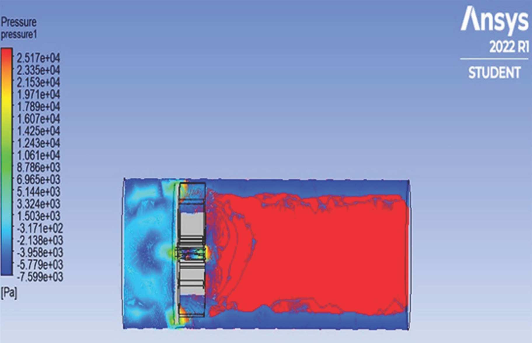
CFD Analysis
Fluid dynamics is a subfield of computational fluid dynamics. CFD analyses and resolves fluid flow problems by using numerical analysis and data
International
of Trend in Scientific Research and Development @
@ IJTSRD | Unique Paper ID – IJTSRD52404 | Volume – 6 | Issue – 7 | November-December 2022 Page 640
Journal
www.ijtsrd.com eISSN: 2456-6470
Fig. 2 Impeller Table 1 Specification of the impeller: S. No. Geometry values 1 Disc
98mm 2 Disc
3 Blade
4 Shaft
5 Radius
6
diameter = 98mm
thickness = 5 mm 5 mm
thickness = 3mm 3mm
hole diameter = 6mm 6mm
of curvature = 30 mm 30 mm
Number of blades = 9 9 3.1.2.
structures.Thefollowingthreestages generallymake up a CFD analysis:
3.1.3. Pre-processing:
The problem statement is now transformed into a customised and idealised computer model. The type offlowthatwillbemodelledisassumedto exist.The creation of the mesh and the use of the initial and boundary conditions are included.
Calculations have already been completed at this point.Therearenumeroussolutions,andtheyallhave varying degrees of ability to address particular physical phenomena.
3.1.4. Solving:
At this point, the computations themselves are finished. There are numerous solutions, each with a unique capacity for addressing certain physical phenomena.
3.1.5. Post-processing:
During the post-processing phase, the results are visualised and examined. We can now review the findings and make judgments. Results obtained in a range of formats, including static or dynamic graphs and tables or graphs and theperformanceis given the graph fig 3.
Input parameters,
The impeller design generates a pressure of 25.17 kpa, according to the CFD analysis. It works well enough to capture dust particles. So 3D printing is used to create this impeller design.
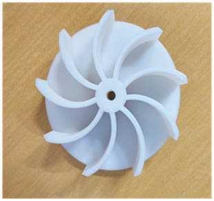
3.2. 3D PRINTING
A digital file is used to build three-dimensional solid things using the additive manufacturing process known as 3D printing. A 3D printed object is made by adding layers of material successively until the desiredshapeisachieved. Theproductobtainedfrom the Company and is given in fig. 4 to fig. 5.
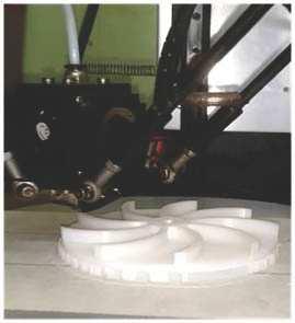
Using polycarbonate, the impeller
produced in this way. Fig. 4
International Journal of Trend in Scientific Research and Development
@ IJTSRD | Unique Paper ID – IJTSRD52404 | Volume – 6 | Issue – 7 | November-December 2022 Page 641
@ www.ijtsrd.com eISSN: 2456-6470
Fig. 3 Post Processing Results Table 2 Input parameters S. No. Input parameters media or values 1 Fluid Air 2 Impeller material Polycarbonate 3 Polycarbonate density 970 kgm 3 4 Rotational speed (N) 6500 rpm 5 Inlet air pressure(Pi) 101325 Pa (absolute) 6 Inlet air temperature(Ti) 30 deg C
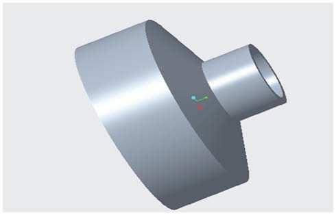
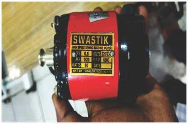
Casing Fig. 5 Inlet Pipe Table 3 Motor specifications S. No. Description Values 1 Volt 230 2 Watts 60 3 RPM 6500 4 HP 120 5 Brand Swastik 3.3. Motor An electric motor is an electrical machine that converts electrical energy into mechanical energy.
is
Motoris used to rotatetheimpeller. It is illustrated in fig.
3.4.
CASING
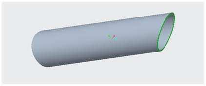
Casing is an airtight chamber surrounding the impeller. In this project 4 inch PVC pipe used as casing fig. 6.
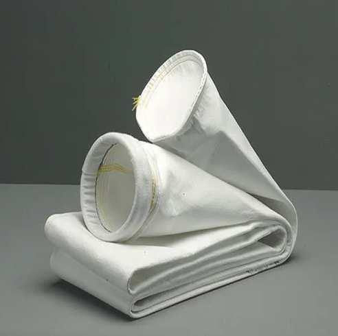
3.5. FILTER
The purpose of the filter is to separate dust from the air fig. 9.
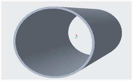
3.6. INLET
A vacuum cleaner inlet hose is a long cylindrical object which connects to a port on a vacuum. Once attached, the suction is pulled through the hose in order to remove dirt, dust, and debris from areas that may be hard to reach using the main section of the cleaner. In this project 1 inch PVC was used as inlet hose. fig. 7
3.7. COLLECTING AREA
A bagless vacuum cleaner includes a separating unit for storing dust. In this project 4/1.5 reducers were used as a collecting area as well as nozzle. fig. 9
3.8. MINI 2 PIN SPST SWITCH
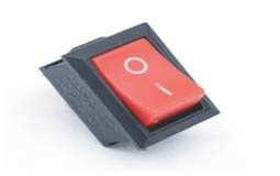
A Single Pole Single Throw (SPST) switch is a switch that only has a single input and can connect only to one output. A Single Pole Single Throw switch serves in circuits as on-off switches. fig. 11.
International Journal of Trend in Scientific Research and Development @ www.ijtsrd.com eISSN: 2456-6470 @ IJTSRD | Unique Paper ID – IJTSRD52404 | Volume – 6 | Issue – 7 | November-December 2022 Page 642
Fig. 6 Casing
Fig. 7 Inlet Pipe
Fig. 8 Motor
Fig. 9 Dust Collecting Bag
Fig. 10 Dust Collecting Section
Fig. 11 Switch
Fig. 12 Exhaust
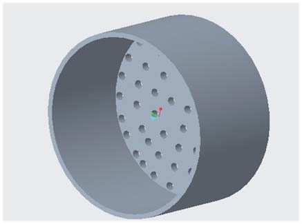
3.9. EXHAUST
Exhaust is used for releasing the filtered air in to the atmosphere. 4 inch coupling with holes are used as exhaust in this project.te diagram is shown in fig. 12
3.10. FABRICATION
STEP 1: The impeller is fabricated by3D printing technology.
STEP 2: The fabricated impeller is fixed with the motor.
STEP 3: The 4 inch PVC pipe is cut into required dimensionsand2holeshavebeencreated for clamping the motor.
STEP 4: Motorandimpellerassemblyfixedinside the casing by clamp.
STEP 5: Holes are drilled on the coupling and the coupling fixed behind casing setup.
STEP 6: Filter is fixed near the impeller.
STEP 7: The 1 inch pipe is fixed into 4/1.5 inch reducer with the help of 1.5/1 inch bush.
STEP 8: Thereducerisattachedto thecasingunit
STEP 9: Handle setup is fixed on the casing.
STEP 10: The wires are connected to the motor for electrical supply, plug and switch are attached on the wire.
STEP 11: The ON / OFF switch is fixed on the handle.
STEP 12: Check the working of vacuum cleaner.
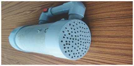
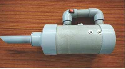
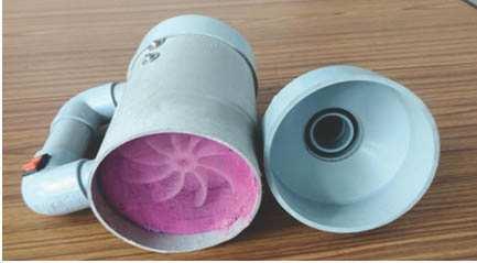
3.11. Assembled Model
The components are perfectly assembled and its various images are given in figs. 13- 15
4. CONCLUSION
Thecentrifugalimpellerisdesignedtoaportablelow cost handheld vacuum cleaner and The designing of components were made in Creo and analysis for the product was done in ANSYS CFD, and impeller was manufactured in the 3D printing machine with polycarbonate material. Also all major parts of the vacuum cleaner are produced from plastics except motor and assembled. The vacuum cleaner works well and performs effectively.
References
[1] Park, Changhwan et al. (2017). “Methodology forsystem-level analysis ofafan-motordesign for a vacuum cleaner”. In: Proceedings of the Institution of Mechanical Engineers, Part C: Journal of Mechanical Engineering Science 231 (20). ISSN: 20412983. doi:10.1177/0954406216651650.
[2] Son, InHyuketal.(2018).“Optimizationofthe flow path efficiency in a vacuum cleaner fan”. In: Journal of Mechanical Engineering 64 (4). ISSN: 2550164X. doi:10.5545/svjme.2017.4736.
[3] Ashish J. Patel, Bhaumik B. Patel (2015). “Design and Flow Through CFD Analysis Of Enclosed Impeller”. In: International Journal of Engineering Research & Technology (IJERT) 3 (7). ISSN: 22780181. doi:10.1016/j.matpr.2015.07.172.
International Journal of Trend in Scientific Research and Development @ www.ijtsrd.com eISSN: 2456-6470 @ IJTSRD | Unique Paper ID – IJTSRD52404 | Volume – 6 | Issue – 7 | November-December 2022 Page 643
Fig. 13 Assembled Model1
Fig. 14 Assembled Model2
Fig. 15 Assembled Model3
International Journal of Trend in Scientific Research and Development @ www.ijtsrd.com eISSN: 2456-6470
[4] “Effects of blade number on characteristics of centrifugalpumps”(2010).In: ChineseJournal of Mechanical Engineering (English Edition) 23 (6). ISSN: 10009345. doi: 10.3901/CJME.2010.06.742.
[5] Gajbhiye, Vijit, Naved Ahmad, and M. S. Tufail(Feb.2018). “Design andApplicationof D.C. Vacuum Cleaner using Axial Flow Fan”. In: International Journal of Engineering and Techniques 4 (1), pp. 467–474. ISSN: 23951303.
[6] Bacharoudis, E. C. et al. (2008). “Parametric Study of a Centrifugal Pump Impeller by Varying the Out-let Blade Angle”. In: The
Open Mechanical Engineering Journal 2 (1). ISSN: 1874155X. doi:10.2174/1874155x00802010075.
[7] Bhosale, Anirudha S and P N Gore (2017). “A Review Paper on Improvement of Impeller Design a Centrifugal Pump using FEM and CFD”. In: IJIRST-International Journal for Innovative Research in Science &Technology| 4. ISSN: 2349-6010.
[8] Khelladi, Sofiane et al. (2005). “Flow study in the impeller-diffuser interface of a vaned centrifugal fan”. In: Journal of Fluids Engineering, Transactions of the ASME 127 (3). ISSN: 00982202. doi: 10.1115/1.1900138.
@ IJTSRD | Unique Paper ID – IJTSRD52404 | Volume – 6 | Issue – 7 | November-December 2022 Page 644