
Online: www.ijtsrd.com e-ISSN: 2456 – 6470
An Automatic Temperature Monitoring and Control System for Electric Power Distribution Panel
Mbamaluikem, P. O.; Okeke, H. S.; Fagbuaro, E. O.
Department of Electrical/Electronic Engineering, Federal Polytechnic Ilaro, Ogun State, Nigeria
ABSTRACT
Apowerdistributionpanelplaysanimportantroleinthedistribution of electrical power in factories or buildings. Through separate wirings, the electrical input that comes into the distribution panel is split up and sent to different parts of the building. At certain temperature, some electric distribution panel components may be highlyflammable,posingafireorexplosionrisk.Asasolutiontothe issue of excessive temperature rise in the distribution panel, an automatic temperature control system was designed and implemented.Theprototypedesignincludesamechanicalthermostat thatalsofunctionsasasensor,anelectricfan,andaminiaturecircuit breaker. The design works in such a way that the temperature controller actuates the cooling system when the panel's temperature reaches 40 degrees Celsius. The results of the test show that the designed system can detect changes in temperature and turn on the coolingfantoensurethepanel'stemperaturedoesnotexceedthesafe level temperature of 40 0C. This system serves as a tool for solving temperaturerecognition issues in electric power distribution panels.
KEYWORDS: Temperature control, mechanical thermostat, distributionpanel,voltage,firehazard,electricpower
INTRODUCTION
Electricityunquestionablyplays an unparalleled role in everyday sustenance, whether in urban or rural areas, in this 21st century. Electricity is used in buildings for running lights, cooking, charging/running electrical appliances, and so on. Electrical wirings are used to transfer electricity safely throughout the building without endangering anyone or any electrical appliances. Because of this, electrical wiring has evolved into one of the most fundamental aspects of our day-to-day lives [1]. Numerous electrical appliances are connected to a networkofelectricalwiringinalmosteverybuilding. However, to guarantee that the electricity is distributed uniformly and evenly throughout the building, an electric power distribution panel is installed alongside the electrical wiring [2].
For the proper distribution of electrical power in factories or buildings, electrical power distribution panels are used. Through separate wirings, the electrical input that comes into the distribution panel is split up and sent to different parts of the building.
How to cite this paper: Mbamaluikem, P. O. | Okeke, H. S. | Fagbuaro, E. O. "AnAutomaticTemperatureMonitoring and Control System for Electric Power Distribution Panel" Published in International Journal of Trend in Scientific Research and Development (ijtsrd), ISSN: 2456-6470, Volume-6 | Issue-7, December 2022, pp.778-782, URL: www.ijtsrd.com/papers/ijtsrd52392.pdf
Copyright © 2022 by author (s) and International Journal of Trend in Scientific Research and Development Journal. This is an Open Access article distributed under the terms of the Creative Commons Attribution License (CC BY 4.0) (http://creativecommons.org/licenses/by/4.0)
Power distribution panels typically have a single central switch that is used to control the flow of electricity throughout a building [3]. When the main switch is turned off, all subsidiary wiring and miniaturecircuitslosespower.Asaresult,consumers place a high value on ensuring the safety of distribution panels because its malfunction will prevent the continuous supply of electric power to variouspartsofthebuildingwheretheyareinstalled. It is stated by [4] that electrical power outages frequently caused by insulation failure in electric powerdistributionpanelshavenotbeensignificantly reduced despite all ongoing preventative measures. This may be due to a lack of information regarding the temperature rise of distribution panels above the safety level (40°C). Furthermore, due to the risk of accidental fire outbreaks in shunt circuits caused by temperature-related insulation breakdown of conductorsandtoavoidconductorburnoutaccidents and save money on maintenance, distribution panels require a fully operational temperature monitoring and control system. To guarantee the panel's and the
International
Volume 6 Issue 7, November-December
@ IJTSRD | Unique Paper ID – IJTSRD52392 | Volume – 6 | Issue – 7 | November-December 2022 Page 778
Journal of Trend in Scientific Research and Development (IJTSRD)
2022 Available
IJTSRD52392
entire electrical installation's safety, a smart system capable of measuring information about general electrical conditions like current, voltage, power, power factor, and temperature is required.
According to [5], temperature control systems are systems that are made to monitor and control the temperature of a room, body, or component under a particularconsideration,andtheyareusedbymodern electrical and smart home devices to control and directtheoperationofelectricalappliances.Theyare designed using either programmable thermostat or mechanical thermostat [6]. Moreover, exposing a body or enclosure to a wide range of environmental stimuli alters the temperature (a fundamental measurement unit that expresses how hot or cold an enclosure, room, body, or environment is) of that bodyand hence, the materials used in building it [7]. As a result, the distribution panel's automatic temperature control system is beneficial because it keeps the temperature within the safe range for the design'smaterials.Thispaperdevelopsatemperaturebased electric distribution panel safety temperature control system.
LITERATURE REVIEW
Warren S. Johnson developed the idea of automatic temperaturecontrolin1880[8] andpatentedthefirst pneumatic temperature control in 1895 [9]. This researchareahasundergonenumerousadvancements and innovations sincethen. To this,[10] developed a temperature controller system using a Proportional Integral Derivative (PID) controller and Lab VIEW. According to [11] temperature control system for home used Peripheral Interface Controller (PIC) Microcontroller 16F877A to decide when to turn on or off the heater or air conditioner to keep the temperature of the room between 200C and 280C. A practicalapproachtooperatingatemperaturecontrol systemforacomputerroomwasprovidedbyutilizing the AT89C51 Single-Chip Microcomputer (SCM, MCU), which is capable of controlling both the temperature of the room and the cooling system by [12].[13]designedatemperaturecontrolsystemthat adjusts the temperature of any device in accordance with its requirements for any industrial application using a PIC16F887A microcontroller. A sevensegment display shows the temperature of the environment that the thermocouple sensor has detected.Theheateristurnedoffifthetemperatureis higherthantheuser-storedvalueforthistemperature, whichvariesbetween0°Cand750°C.Arelayandan NPN transistor serve as interfaces between the system's switching state and the microcontroller. Research by [13] resulted in the development of a temperature-controlled system for an air-filled
chamber with less than 10K overshoot and steadystate temperature error in the real chamber temperaturestep response. Thesystem was designed to handle the target chamber temperature within a specified time frame. The development of a dualsensorheatmonitoringsystemwastheprimaryfocus of the study of [14]. While monitoring temperature from an external input, the circuit describes the current temperature to a predetermined temperature value. According to the findings of the test, an alarm was set off and the power output of the circuit was turned off whenever the temperature of the device exceeded a predetermined threshold [15].
DESIGN METHODOLOGY
A novel method for controlling and monitoring the temperature of an electrical power distribution panel is presented in this paper. A temperature sensor, a cooling system, and a power supply made up the system. The mechanical thermostat maintains the ability to turn on and off the cooling system. The system is set up in such a way that the temperature sensor bulb serves as the mechanical thermostat's input,whichitusestocontrolthedistributionpanel's cooling fan. For this system, thedanger alarm would go off and the circuit breaker would trip if the temperaturecontinued to riseabove500C. Theblock diagram of the temperature monitoring and control system (ATMCS) for electric power distribution panel is shown in Figure 1.
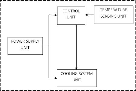
Figure 1: Block Diagram of ATMCS for electric power distribution panel
Power Supply
Toprovidetherequiredpower,eachelectroniccircuit requiresapowersource,whichcouldbeabatteryora mains supply. To obtain input power from the mains supplyandsupplyaDCsourcetothemonitoringand control circuits, the design makes use of a 220 V AC/DC miniature circuit breaker.
Control unit
TemperaturesensorssuchasThermistors,Resistance Temperature Detectors (RTDs), LM335 and/or AD590 are frequently utilized to keep systems at a
International Journal of
in Scientific Research and Development @
@ IJTSRD | Unique Paper ID – IJTSRD52392 | Volume – 6 | Issue – 7 | November-December 2022 Page 779
Trend
www.ijtsrd.com eISSN: 2456-6470
constant temperature. A precision temperature controller uses a current or voltage source to supply power to these actuators based on data from a temperaturesensor.Accordingto[16],thesekindsof sensorscanfrequentlyachievestabilityrangingfrom 0.01°C to 0.001°C. For dependable qualities of 1°C, other less precise sensors like thermocouples can likewisebeused.Nevertheless,thearchitectureofthe system determines the stability. Hence, with the end goalofthisplan,thetemperatureregulatorutilizedis the Mechanical thermostat. To keep the distribution panel at the safe temperature, this mechanical thermostat precisely controls when the cooling fan comes on and off. The used mechanical thermostat can be set to a temperature between 30 and 110 degrees Celsius. The internal architecture of the mechanicalthermostatanditsphysicalappearanceare depicted in Figures 2 and 3, respectively.
hand, some temperature sensors, known as "noncontact temperature sensors," do not require direct contacttomeasureanobject'stemperature.Thereare various kinds of temperature sensors, including Resistance Temperature Detectors (RTDs), Thermocouples and thermistors, and infrared (IR) sensors - a non-contact temperature sensor. A temperature sensor for a thermostat is used in this design. The thermostat's sensing bulb is responsible for detecting the temperature in the panel. The temperature-sensing bulb is depicted in Figure 4.
Figure 2: An internal view of a Mechanical Thermostat
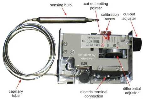
Figure 4: Temperature Sensing Bulb of the Thermostat
The cooling system
A cooling system is one that maintains the temperatureofanengineorstructure.Thepurposeof coolingsystems is to removetoo much heat from the area they are supposed to cool, thus keeping the temperature of the compartment at the desired level. A220VdcAxialIndustrialFanisusedtoachievethe type of cooling system that is utilized in this design. The industrial cooling fan's physical structure is shown in Figure 5.
Figure 3: Physical outlook of the mechanical Thermostat
Temperature Sensing Unit

A temperature sensor is a device that converts the input data into electronic data and keeps track of the surroundingtemperature.Sometemperaturesensors, known as "contact temperature sensors," require direct contact with the physical object whose temperatureistobemonitoredtogatherinformation. On the other
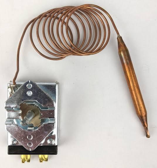
Figure 5: An Industrial Cooling Fan.
MATERIAL SELECTION
To accomplish the study's goal, various materials were chosen and are listed in Table 1.
International
in Scientific Research and Development
@ IJTSRD | Unique Paper ID – IJTSRD52392 | Volume – 6 | Issue – 7 | November-December 2022 Page 780
Journal of Trend
@ www.ijtsrd.com eISSN: 2456-6470
Table 1: Selected Materials for the ATMCS S/N Components Features Specification
1 Miniature circuit breaker
2 Industrial cooling fan (an axial type)
3 Mechanical Thermostat

input voltage 220 Vac Current 13 A Output voltage range 220 – 400 Vdc
Current 5A Voltage 220 Vdc
temperature range 30°C to 110°C Voltage range 220 – 400 Vdc
SYSTEM IMPLEMENTATION
The selected components were connected in the manner illustrated in Figure 6.
@ www.ijtsrd.com eISSN: 2456-6470
artificial heating element was used to simulate the performance of ATMCS. The enclosed panel's temperature was raised by this heating element and the ATMCS's performance was observed and recorded as thetemperaturerose. As thetemperature was raised or lowered by 5°C increments, the fan's state was observed and recorded. Tables 2 and 3 summarize the findings.
Table 2: The performance Test of the ATMCS as temperature increases
Temperature (℃) State of the Cooling Fan Operating Test Time (S) 30 OFF 600 35 OFF 600 40 ON 300 45 ON 300 50 ON 300
Table 3: The performance Test of the ATMCS as temperature decreases
Temperature (℃)
Figure 6: The wiring diagram of the system. Thetemperaturesensingbulbautomaticallymonitors the temperature of the distribution panel. The obtained data is fed into the mechanical thermostat, whereitwillbeprocessedandusedtoturnonandoff the cooling fan. Figure 7 depicts the installed ATMCS in the distribution panel.

State of the Cooling Fan Operating Test Time (S) 50 ON 300 45 ON 300 40 ON 300 35 OFF 600 30 OFF 600
The time allotted for the system to function under each temperature value is represented by the operating test time in Tables 2 and 3. To ensure safety, the operating test time was reduced as the temperature rises. According to Table 2, the cooling fan was turned ON when the temperature reached 400C,changingitsstateinthetablefromOFFtoON. Thiscorrespondswiththesettimeonthemechanical thermostat.Atthispoint,thetesttimewasreducedto 5 minutes as against the initial 10 minutes used initially. The cooling fan's status also changed from ON to OFF when the panel's temperature dropped to 350C as shown in Table 3. Here, the operating test time was then increased back to 10 minutes.
Figure 7: The Picture of the ATMCS installed in Electric Distribution Panel
RESULTS AND DISCUSSION
The ATMCS was made to function when the temperatureintheenclosureisabove400C.Theideal working temperature for the majority of the electric distribution panels liebetween the rangeof 40℃ and 50℃.Thelifespanofthecomponentsdecreasesasthe internal temperature rises. In this design, any temperatureabove40°Cisregardedasabnormaland is not anticipated to occur under normal operating conditions.Asaresult,thecoolingfan isactivated to evacuate the thermal energy from the enclosure. An
CONCLUSION
The electric power distribution panel's automatic temperature monitoring and control system has been successfully implemented in an electric distribution panel. The system performance is satisfactory. As a result, the project's aim was achieved. This system can be utilized in bakeries, incubators, houses, halls, offices, and other locations where a particular constanttemperatureisrequired.Forenclosurebigger thanthesizedused,athree-phaseinductionmotorfan may be utilized because of its robustness and heat handlingcapacityand goodperformanceunderother climatic variables. Moreover, a digital thermometer
in Scientific Research and
@ IJTSRD | Unique Paper ID – IJTSRD52392 | Volume – 6 | Issue – 7 | November-December 2022 Page 781
International Journal of Trend
Development
International Journal of Trend in Scientific Research and Development @ www.ijtsrd.com eISSN: 2456-6470
that only allows a temperature variance of plus or minus 0.1°C should be used as the temperature controller,toincreasethecoolingsystem'sefficiency, length of service, and for better precision.
REFERENCES
[1] Jakomin, M. (2011). Shallow Axi-symmetric Bimetallic Shell as a Switching Element in a Non-Homogenous Temperature Field. Engineering, 3(2), 119.
[2] Li, Y., & Crossley, P. A. (2014, July). Impact of electric vehicles on LV feeder voltages. IEEE PES General Meeting| Conference & Exposition, 1-5.
[3] Wati,T.,Sahrin,A.,Suheta,T.,&Masfufiah,I. (2019). Design and Simulation of Electric Centre Distribution Panel Based on PhotovoltaicSystem. IOPConference,(pp.462 - 467).
[4] Arghandeh, R., Onen, A., Jung, J., Cheng, D., Broadwater, R., & Centeno, V. (2013). HarmonicImpactStudyforDistributedEnergy Resources Integrated into Power Distribution Networks. InAmericanSocietyofMechanical Engineers Power Conference, 56062, V002T09A009.
[5] Abubakar, M. A., Adepoju, T. M., Rabiu, M. L., & Muslim, U. A. (2017). Microcontroller Based Automatic Temperature Controller. International Conference of Science, Engineering & Environmental Technology, 2(16), 127-131.
[6] Anusa. (2021). Temperature Control System. Retrieved August 15, 2022, from Electronic Hub: https://www.electronicshub.org/temperaturecontrolled-system/
[7] Deepika. (2006). Designing a Microcontroller Based Temperature Data logger.” Master Thesis submitted to the department of Electronic and Instrumentation, Thiapar Institute of Engineering and Technology, Patiala.
[8] ASME. (2022, AUGUST 11). the first automated temperature control system Retrieved from The America Society of Mechanical Engineers: https://www.asme.org/about-asme/engineeringhistory/landmarks/244-multi-zone-automatictemperature-control#
[9] Nyiekaa, E. A., Francis, C. A., & Ukor, K. J. (2021). Design and Construction of an Automatic Temperature Control System. Journal of Scientific and Engineering Research, 8(6), 84-91.
[10] Muhammad,A.H.,NurDalila,K.,Muhammad, H., & Muhammad, F. R. (2017). Development of Experimental Simulator via Arduino-based PID Temperature Control System using LabVIEW”. Journal of Telecommunication, ElectronicsandComputerEngineering, 9 (1).
[11] Lwin, M. A. (2019). Implementation of Home Temperature Sensing Control System Using Microcontroller. InternationalJournalofTrend inResearchandDevelopment(IJTRD),6 (2).
[12] Xu, K. L. (2015). Design of Temperature ControlSystemforComputerRoomsBasedon AT89C51 Single chip. Chemical Engineering Transaction.,46, 271-276.
[13] McDonald, J. S. (2017). Temperature control using a microcontroller: an interdisciplinary undergraduate engineering design project.
[14] Zungeru, A. M., & Ahmed, M. S. (2012). Development of a Dual Sensor Heat Control System. arXivpreprintarXiv,1210, 8378.
[15] Tang, C.W.(2016).Temperaturesensorbased on the temperature memory effect in shape memory alloys to check minor over-heating. SensorandActuatorA:Physical, 238,337-343.
[16] Gosar, Z., & Kosel, F. (2013). Experimental analysis of Kinamatics of snap-through of the shallow axisymmetric parabolic bimetallic shell. Internationaljournalofbasic&applied science, 13(4), 23-29.
@ IJTSRD | Unique Paper ID – IJTSRD52392 | Volume – 6 | Issue – 7 | November-December 2022 Page 782