16 minute read
Additive manufacturing with glass for facade applications
from IM20202EN
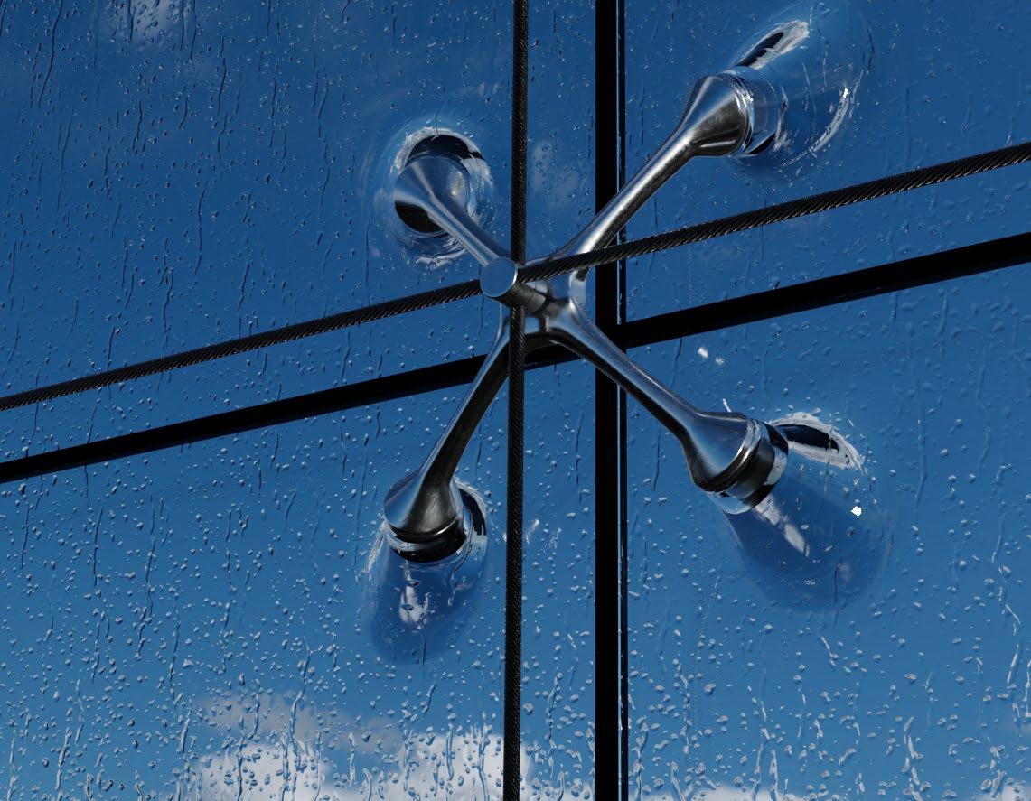
Figure 1: Render showing an envisioned future spider connection using additive manufacturing with glass
Advertisement
Over the last decades, the role of glass has become more and more prominent in modern facade engineering. Because of its rare combination of strength, transparency and durability, glass offers a unique combination of material properties that trigger the imagination from a variety of industries such as buildings, cars, yachts, interior design, optics, glassware, art, tableware, data cables, etc. Glass is perceived - depending on the mixture - as transparent or translucent, as colored or clear. Despite the fact that glass is often addressed as such, glass however is never invisible. The TU Darmstadt, specifically the Institute of Structural Mechanics and Design (ISMD), the Center for Structural Materials (MPA-IfW) and the Glass Competence Center (GCC), are exploring the potential of additively manufactured glass components in terms of material behavior, printing technology, structural behavior, design and envisioned applications.
Additive Manufacturing
When we think about 3D printing, there is a great variety of additive processes available today. What connects these techniques, such as Rapid Manufacturing, Rapid Tooling, Rapid Prototyping or, more generally, Additive Manufacturing (AM), is the fact that they are all based on 3D computer generated data as a framework for a manufacturing process. The desired components are digitally designed via a computational tool before this data is then converted in an applied computer language, which commands the AM system to manufacture this specific component. The most commonly used methods of additive manufacturing are (figure 2): or the building plate, any 3-dimensional coordinate within the printer’s volume can be reached.
a) Stereolithography (SLA): This technique describes a layer by layer printing style in which a light source causes monomers in a bath to link together to form polymers.
b) Selective Laser Sintering (SLS): In this technology, a laser beam is used as power source in order to locally sinter powdered material together. The laser is aimed at specific points derived from a 3D model, only creating a solid structure where desired. The technology is closely related to Selective Laser Melting (SLM), whereas the main difference is that the material in SLM fully melts rather than being sintered leading to differences in material properties such as crystal structure, porosity, etc.
c) Fused Deposition Modelling (FDM): This technology is a continuous filament fed process through a heated nozzle, thereby depositing a complex geometry layer by layer. By moving the nozzle and/ differs from FDM as it does not rely on direct solidification or drying to retain its shape after extrusion. Instead, the entire printed and often still fragile part is afterwards dried and sintered to attain its final mechanical properties.
a) b) c)

d)
Figure 2: The most commonly used methods of additive manufacturing, a) SLA, b) SLS, c) FDM, d) DLP & e) DIW
e)
d) Digital Light Processing (DLP): This technology presents a similar process as SLA, the main difference being the source of the light. By using a more conventional light source and applying it to the entire surface of the resin in a single pass, it is generally faster than SLA.
e) Direct Ink Writing (DIW): This technology, which is also known as robotic material extrusion, shows great similarity to FDM printing, since a small nozzle extrudes filament or a paste whilst it is moved across a building platform. It terms of freedom of form. The freedom that is provided by these technologies in terms of form might include better structural and technical material or product properties, next to an increase of individual design options. If we look at the current state of additive manufacturing, it can be seen that components made of metals and plastics have experienced severe attention from researchers worldwide over the last years and can be considered a state-ofthe-art technology in several industries. Compared to metals and plastics, AM of glass can still be considered within an embryonic state of research.
All these methods have in common that they convert 3D data into physical models without extra tooling by solidifying layers of material on top of each other. Having a large pool of applicable materials enables the engineer to develop a wide range of fields for which products can be manufactured. Nowadays, all these methods of AM use either one or two materials at a time, and crossing these processes and thereby improving material properties seem to be the core of the matter.
Next to cost and material efficiency as arguments to justify the usage of AM technologies, a third and at least equally important argument can be given in
AM Glass
Until now, roughly 25 documented projects have focused on AM with glass, with the earliest project dating from 1995 by the University of Texas, USA. In recent years, the spectrum of research on this topic has increased significantly. The projects are driven by a wide range of industries such as optics, architecture, bio engineering, microfluidics and more. In these projects, many different printing techniques and glass types have been investigated. Moreover, a variety in scale level can be identified ranging from printed glass samples of less than 5 mm in diameter and a resolution of 150 µm up to glass objects with a diameter of around 25 cm with a resolution of around 5 mm. The most well-known projects concerning AM glass were done by MIT as is published in Innovative Materials volume 1 2019. At the TU Darmstadt, the reason for researching AM with glass was initially driven by the Institute of Structural Me-
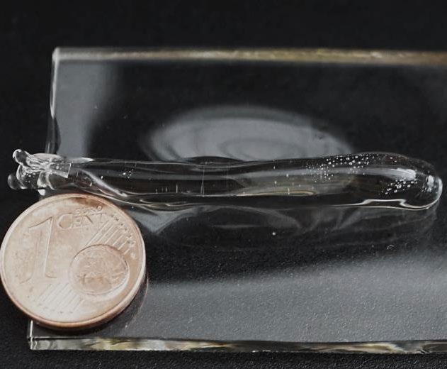
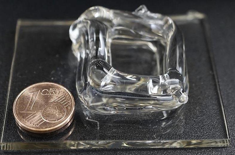
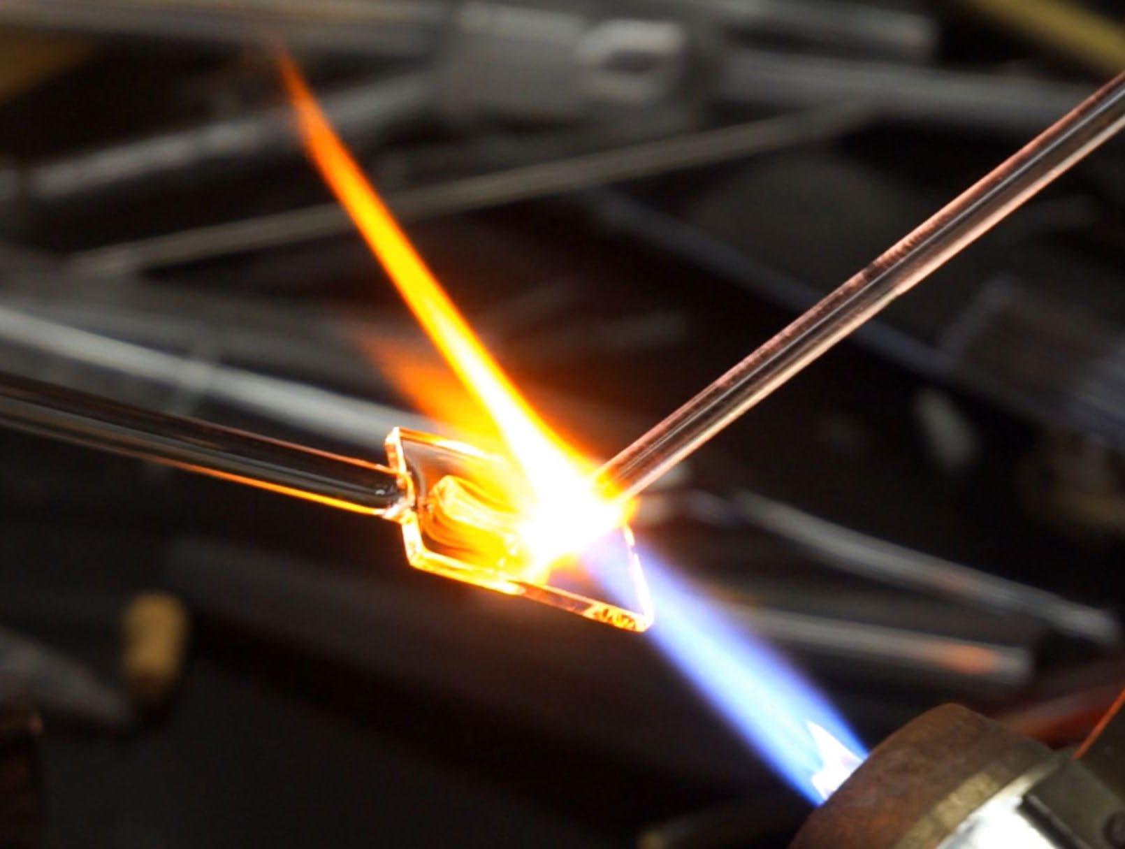
chanics and Design (ISMD), department of Façade Technology. By analyzing the current way of fixing glass façade panels it became imaginable that it would be possible to eliminate the necessity for adhesives or boreholes including their associated disadvantages such as ageing and premature failure of the glass plate. As a potential solution, the TU Darmstadt envisioned the option to print glass connection sockets directly on top of a glass plate in order to connect them (see figure 1). To investigate this, a proof of concept needed to be established which initiated the cooperation between ISMD, the Center for Structural Materials (MPA/IfW) and the Glass Competence Center (GCC) of the TU Darmstadt. The aim for this proof of concept was to obtain a connection between a glass plate and the deposited glass in such a way that load transfer would be possible through this fused area. The research included experiments with soda-lime-silica and borosilicate glass and produced point, line and stacked spline samples as shown in figure 3.
A decision was made to manufacture these samples by hand using the experience of the glass blowers from TU Darmstadt’s faculty of Chemistry. These hand-made samples offer sufficient quality for a proof of concept and will also form a base of knowledge on which the blueprints for a future glass 3D printer are based. The main challenge for building this printer is namely converting the knowledge and experience of craftsmen into an automated machine, translating subjective skill into objective parameters such as temperatures, printing speed, extrusion rate and many more (see video on page 18: Workshop glass fusing). This machine is necessary to make objects with repeatable quality in a highly controlled environment in which process temperatures range from room temperature to more than 1000 °C. A great challenge in the manufacturing process is the thermal and brittle material behavior of glass. Thermal residual stresses, pores and material inhomogeneity (e. g. crystallization) can occur during manufacturing, with the result of possible glass breakage. After producing the glass samples, material and component investigations were conducted in order to analyze homogen-
a)

b)
c)
a)
b)
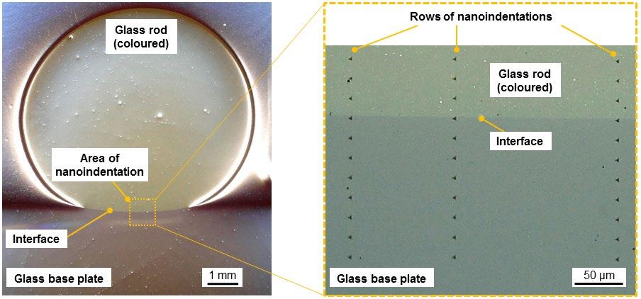
Figure 4: Microscope image of a line fused glass rod (colored borosilicate glass) and a glass base plate (borosilicate glass) a) overview (cross-section, sharpening sample), b) nanoindentations in the joining area
eity (residual stress, morphology, etc.) and performance (strength, hardness) of the joining area and the interface between fused glass layers and flat glass (figure 4). The point fused samples were then subjected to a destructive bending test which showed promising results. Results show that load transfer through fused glass joints is possible, thereby proving the concept and passing a green light for building a 3D printer to automate the process and take the research to the next level in 2020.
Potential applications
As already shown in figure 1, a potential application that logically comes to mind from the perspective of the department of Façade Technology is to use AM glass for the design of glass connections directly on top of a glass plate. From a design perspective, you can imagine the range of options available in terms of transparency and freedom of form whilst eliminating current engineering problems related to adhesives or boreholes. Moreover, it would be possible to locally print glass on top of a glass façade panel in order to stiffen the plate where necessary according to its structural analysis, hereby minimizing both the amount of material used and the total weight of the glass panel A third application from the perspective of façades would be to use AM glass for a new generation of Vacuum Insulated Glazing (VIG) in which the small black spacers between the two glass plates could be replaced with transparent glass spacers directly printed on one of the glass plates. It would also be a possibility to use AM glass in a way to seal the
a) b) c)

d)
perimeter of the glass unit, comparable to a welding process. As a fourth, it is imaginable that a higher degree of transparency is desired for insulated glass units (IGU). AM Glass could eliminate the necessity for the (highly visible) spacer, reducing the size of the seam (often Butyl) to minimal proportions.
From the perspective of other industries, it is imaginable to use AM glass in the car or yacht industry as stand-alone objects or to add new functionality directly printed on the glazing of a car/yacht. Also for interior designers, this technology could open an entire new spectrum of design possibilities, with direct bathroom applications imaginable such as taps, shower enclosures or decoration. The optics industry is also directly a potential area for implementation of AM glass, based on their desire for complex glass objects with extremely high quality and accuracy which is imaginable with a computer controlled technology such as AM glass. Whichever way additive manufacturing with glass will exactly develop, the TU Darmstadt aims to be on the frontier with state of the art research, continuously pushing the boundaries.
Robert Akerboom, Matthias Seel
TU Darmstadt The article ‘Fused glass deposition modelling for applications in the built environment’ is online (pdf)>
Research team: Robert Akerboom 1 , Matthias Seel 2 , Ulrich Knaack 1 , Matthias Oechsner 2 , Jens Schneider 1 , Peter Hof 2
1 Technical University of Darmstadt, Faculty of Civil Engineering and Environmental Engineering, Institute of Structural Mechanics and Design, ISMD, Franziska-Braun-Straße 3, 64287 Darmstadt, Germany.
2 Technical University of Darmstadt,
Center for Structural Materials, MPA
IfW, Grafenstraße 2, 64283 Darmstadt, Germany.
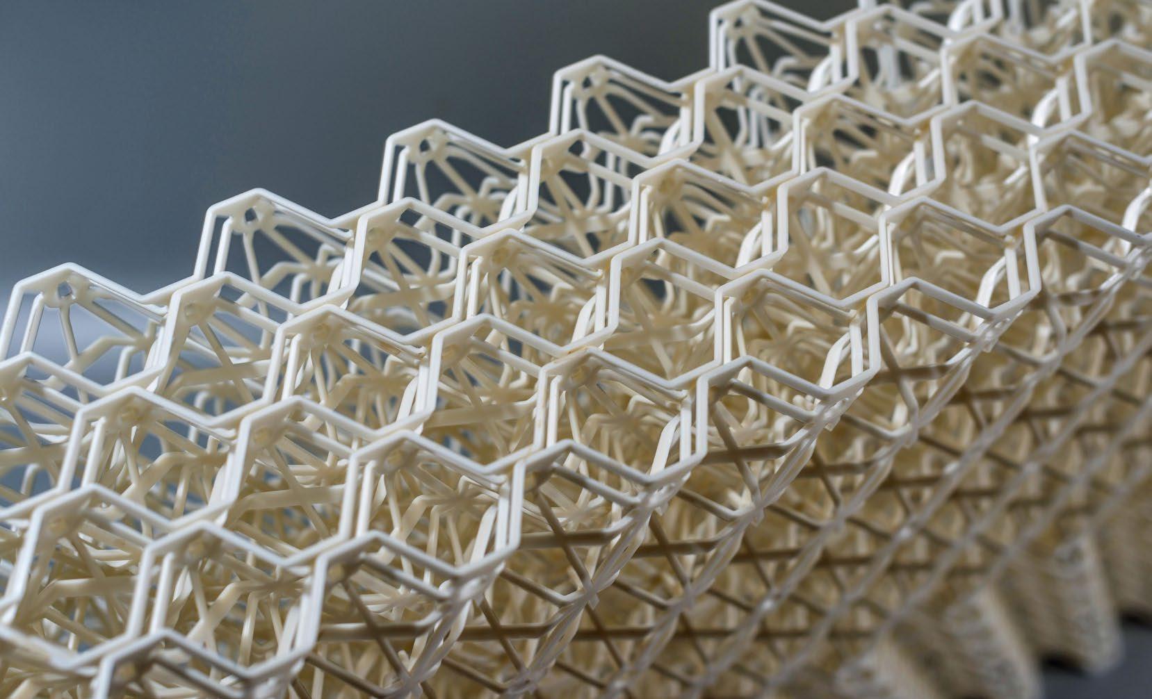
Figure 1: BESE-elements. Module composed of 6 layers. The layers have a size of 922x455x20 mm each
Nature structure: Potato scraps have a new purpose at sea
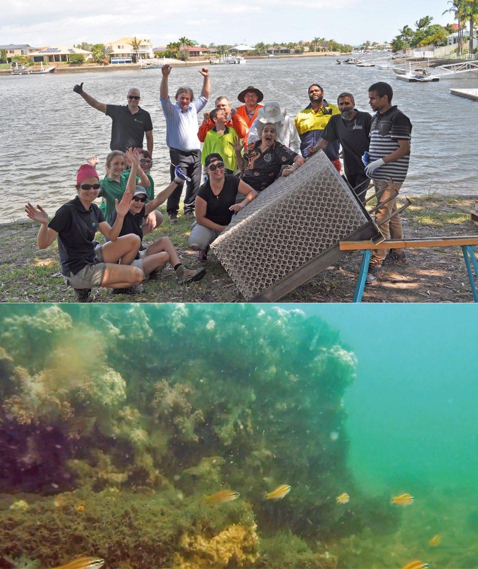
Dutch marine biologists recycle potato waste into mats that they use for nature restoration, like salt marshes, reefs and seagrass meadows. These Biodegradable Elements for Starting Ecosystems, or BESE-elements, consist of stackable layers that build up into a biodegradable matrix structure (fig 1). The modular design combines porosity with a complex structure. In a way it resembles the well-known building blocks: a simple design with endless possibilities. Now worldwide tests for nature restoration have been set up with the material.
The material was created by a collaboration of parties who consider it important that materials that we use in nature and for nature restoration do not remain in nature. To this end, a link has been established between a party with knowledge of nature practice, a university with knowledge of how nature functions, a company with experience in injection moulding and a company specialized in processing waste streams into biopolymers. After two years of development, with numerous challenges, the first batch of BESE-elements was available in 2013. A first test was carried out in 2014 in the Wadden Sea, the Netherlands.
Potato farm
Coral Oyster/mussel
Mangrove Sea grass Salt marsh
Ecosystem restoration projects

ELEMENTS
Potato chip factory
Chips
Starch (waste)
Biopolymer factories
Figure 2: The waste from the French fry industry serve as one of the raw materials for the biopolymers in BESE-elements
Nature foundation
The modules serve as a starting point: a temporary structure that provides adhesion, stability and protection for organisms, both plants and animals. Normally nature provides this, but, due to human activities, structure-forming plants and animals in nature have disappeared in many places. Many young plants and animals are not able to start in a new place without the protection of the parents: the conditions are just too harsh. The artificial structure temporarily takes over protection, inhibits currents and waves on a small scale. After establishment, nature itself forms a structure and artificial support is no longer necessary. After a while, nature can take over and the material can slowly break down.
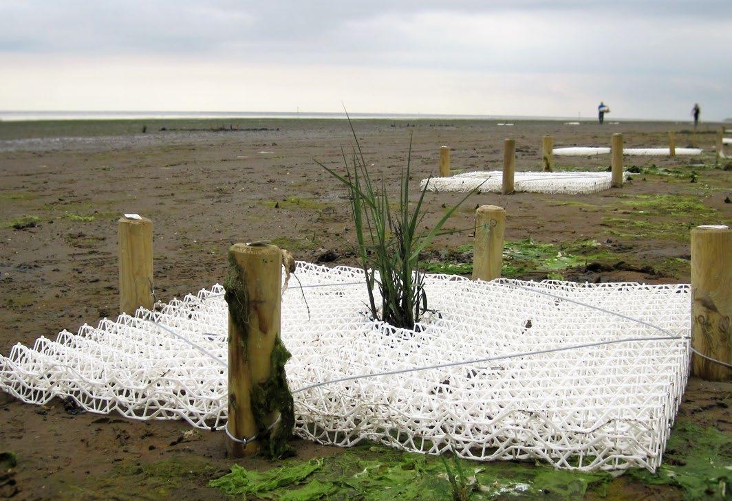
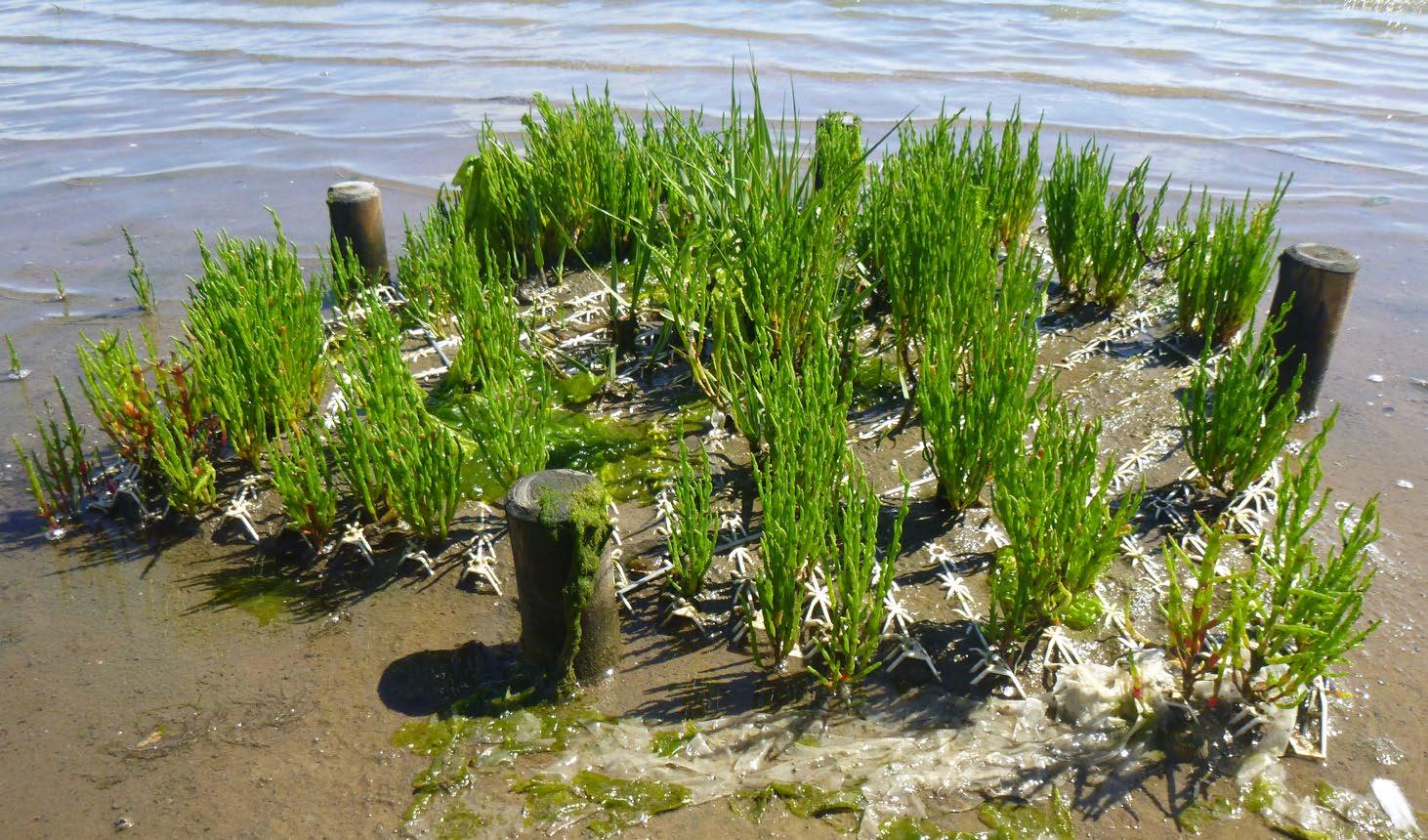
Figure 3b: BESE-elements with salt marsh plants (Salicornia en Spartina) in the Netherlands one year after placement. Plants without a structure have also been placed in the same location but did not survive
Material properties
The material consists of single layers, that are stackable for transport and can then be clicked together on site (fig 1). The clicked layers form a complex 3-dimensional structure, with a large surface-area and many cavities. The renewable raw material, Solanyl, is biodegradable, carbon neutral and non-toxic.
Shape
The material is designed for modular assembly and installation, allowing for different combinations, structure heights and dimensions depending on the needs (fig 1). The basic element is a rectangle of approximately 0.5 x 1 meter. The number of layers and the shape are adjusted to the desired location, application or type of restoration needed. The color can be adjusted as desired with a biodegradable dye.
Biodegradable
The material is made from Solanyl, a renewable raw material consisting of a mixture of biopolymers. An important component that has been used as raw material consists of potato residues from the French fry industry (fig 2). The material complies with Vincotte OK Compost and is certified in accordance with EN13432 (industrial composting). The degradation is done by micro-organisms and ultimately results in water, carbon dioxide and microbe biomass.
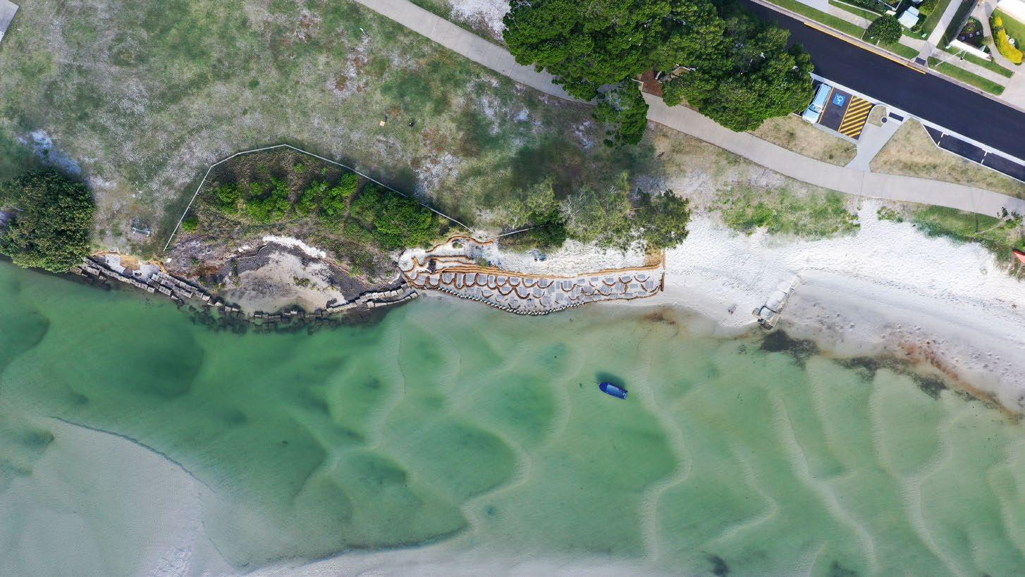
Figure 5: Mangrove restoration with BESE-elements® in Pumicestone passage, Australia (photo: HLW)
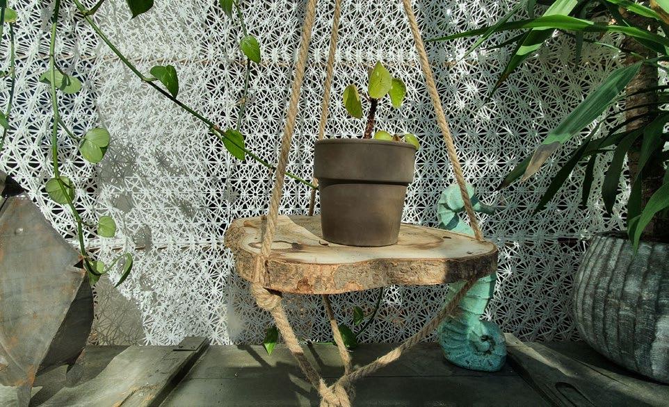
Outside the controlled composting environment used by the certifying bodies, biodegradability is a process that is subject to its environment. In comparison, a table made of bare wood, a material that is biodegradable, can last for centuries in a dry indoor climate, but will quickly rot away in a moist forest. Thus far, a strongly varying breakdown time of the material is observed at different locations. In a freshwater spring in Florida the material was totally soft after only three years. In open water, situated in the temperate climate zone of the Netherlands, it may take one or more decades. Therefore a second mix of the material is available since 2019 that breaks down more quickly, in approximately one or two years. Nature restoration, including salt marshes, mangroves, sea grass, dune vegetation, reefs and peat bogs; Aquaculture and water quality; (Underwater) habitat creation. the Boston Society of Architects (‘NatureStructure’ 2018, with book edition in 2020) and in Amsterdam, Huis Marseille, (‘When Red Disappears’, Elspeth Diederix 2019). The material is used at exhibitions and in shop windows (Fig 6).
Award and expo
The structure was awarded the first prize of the Circular Innovation Challenge of the Water Boards in 2018. The material has also inspired architects and artists and has been exhibited at Art Park, Warapuke, New Zealand (‘Biobased Experiments’ Natasja Rodenburg 2017),
The main application, currently used in locations across four continents, are water systems and coastal ecosystems that suffer from human activities. These ecosystems are of great importance, including for coastal protection, drinking water supply, recreation and aquaculture. That is why it is especially important for these systems to protect and restore nature, for example by using Biodegradable Elements for Starting Ecosystems. The possible applications for these 3D structures are numerous. A selection of the possibilities (fig 3, 4, 5):
Worldwide applications
Tekst: Bureau Waardenburg
Glass-foam-concrete sandwich
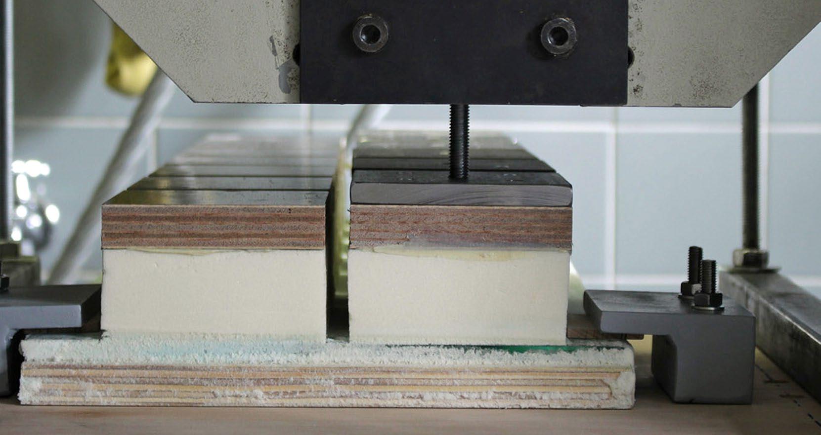
Last January, detail-online.com payed attention to the research project ‘Composite connection in glass rigid-foam concrete sandwich elements’ of the University of Siegen. The research focussed on a new type of sandwich element made of concrete, polyurethane rigid-foam and glass for use in facades. Composite thermal insulation systems are not new. They usually consists of a load-bearing supporting shell of reinforced concrete, a thermal insulation layer of rigid foam and a facing shell. The connection between these separate layers is usually mechanical and accomplished with fasteners. Skipping these fasteners would be interesting in terms of material savings and manufacturing complexity as well as improved thermal resistance with a lower component thickness. And that’s exactly what the Siegen researchers have investigated. the University of Siegen, a new type of sandwich construction was developed in which glass panels as facing layer are connected via the insulation layer to a reinforced concrete bearing layer without any mechanical anchorage. The tensile and shear forces, are transferred in the interface layers between the three materials exclusively by adhesion.
Various tests were carried out to characterise the bond between various rigid foam panels and cast-on ordinary performance concrete (OPC) as well as ultra-high performance concrete (UHPC). The rigid foam panels consisted of expanded polystyrene (EPS), extruded polystyrene (XPS) and polyurethane (PUR) and had different surface textures. Especially different surfaces in the composite joint between the glass and insulating material were investigated, as well as between the concrete and insulating material. The analysis of the fracture surfaces shows the importance of the use of an adhesion promoter. The rigid foam processed with an adhesion promoter has significantly smaller pores in higher numbers at the interface to the glass. Compared to rigid foam without adhesion promoter, this results in a larger effective area for the transfer of adhesive tensile and shear forces, which leads to higher strengths between the glass surface and the rigid foam. The research shows the technical feasibility of strong glass rigid-foam concrete sandwich elements. However, further tests are required to understand how the material behaves under mechanical and climatic stresses.


