10 minute read
RESONANCE
Yetanother dispatch written on an airplane (or started on one), due in part to the fact that I’ve been over the Atlantic every week for the past few months, and it’s the only free time I’m afforded. My last ITMN submission included a picture of Mosport (CTMP) taken out of the window of a B787.
A couple of weeks ago I got to the Indianapolis IMSA event from England in a seriously convoluted way; flew London-Toronto, immediately followed (like out of the terminal and into a rental car) by a drive to Chatham, Ontario to grab a few hours’ sleep (don’t ask, was a lack of planning), and then onward to Detroit the next morning to attend the second year of its reimagined auto show (having been rebranded and cleverly moved from the depths of Michigan’s freezing January to a more hospitable September, but missing both 2020 and 2021 due to the pandemic) where Ford featured the Mustang GTD as a follow-up to the first unveiling in Monterey. Multimatic plays a key role in that program (no secret) but more on that in a later article, along with how that road version has a deep connection to the GT3 race car.
Then, after a “big night” at the Apparatus Room (highly recommended), it was onward to Indianapolis chasing Harry Tincknell all the way for four hours (or maybe it was more if we stayed to the speed limit). Was a great IMSA Sportscar weekend for the LMDH
Porsches with Penske finishing one-two and Harry throwing down some top three stats in outright lap time and stint average, having had to drive from the back due to a pit lane infraction for the Proton privateer Porsche. The car is becoming a formidable competitor with a combination of Multimatic, Porsche and Penske development. I stayed in our old, converted GMC Greyhound bus for the weekend, parked up against the backstraight fence amongst a load of serious enthusiasts. Way better than restaurant dinners and hotel rooms every night, and a good place to do business during the day. Andrew Holt joined me as he works for Multimatic in a manufacturing plant just up the road in Fort Wayne, Indiana (#itsnotthatbad...that’s a real motto, and it truly ain’t so bad). Stayed at his place on Sunday night, finishing off the weekend with street tacos and a bunch of beers before driving all the way back to Toronto on Monday to catch the red eye to London. Wears me out just writing about it.
But I love the Speedway, the awesome sports car racing that IMSA is serving-up and being involved with our at-track support team, who are fully amazing.
I’m now on another B787 and have already thrown down 400 words just covering my recent travel itinerary. So, what of interest have I got to share this issue? A blast from the past. And not specif- ically race related, but some cool technical stuff that made it to the front of my conscious when I recently found a missing photo album (had written it off as lost). Dark ages stuff. Not quite back to my time working on a Lola T212 in the early 1970s, but a decade later, towards the end of my university marathon. Two specific projects, one the subject of my undergraduate thesis, and the other being Ryerson’s SAE Supermilage/Shell Fuelathon entry. Note that Ryerson has recently been renamed Toronto Metropolitan University…pretty bland, but I don’t disagree that it needed the change for reasons not to be expounded upon in this article. Both projects are wholly engine related. As I have explained in previous scribblings, before ending up specializing in structural engineering and later chassis development, I was a truly committed engine man. And, as I elucidated in my previous piece on two-stokes (ITMN 26.01), those stinky, noisy, recalcitrant versions of the internal combustion engine were my fixation. I won’t repeat all the stuff I hitherto shared around racing (motocross as a rider, road racing as a tuner) but I will expand on my thesis project because I have now found the long-lost pictures which brought the highly ambitious undertaking back into focus.
The title of my research was “The Design and Development of a Speed Sensitive, Variable Tuned Length, Two-Stroke Exhaust System” which pretty much explained exactly what I was up to in the dark ages of 1982 and 1983. Again, for a proper elucidation of the magic of two-stroke engines go back to my previous article on the subject, check out Wikipedia’s description (pretty good), or browse the load of really cool related YouTube videos, and if you are really hooked try and get a copy of Gordon Jennings’ most excellent book Two-Stroke Tuner’s Handbook (where I learned how to design expansion chambers, but not so much fabricate them, which is a pure art).
The true secret of unleashing the real potential of a two-stroke comes from taking advantage of the resonances in its exhaust (not an obscure concept in any internal combustion engine but a critical aspect of a two-stroke) which makes the difference between a smoky little shitbox (the BSA Bantam of the early sixties) and a world championship capable power plant (the MZ, from the same period…latterly Suzuki…read my previous piece for that link). It all comes down to harnessing the concept of the Helmholtz Resonator (and despite that acoustic phenomenon partly encompassing my surname, I will go no further on explaining the science behind it, Wikipedia does a great job of that).
For the basics I will reiterate the explanation of the expansion chamber from my previous article as follows: Referencing Figure 1, an expansion chamber is made-up of a header pipe (1) (into which the exhaust port dumps the burnt gasses), a diverging (expanding) cone (2), a straight chamber (3), a converging cone (4) and a tailpipe (5). It’s generally configured to get the burnt gasses out to atmosphere like a normal exhaust, but more importantly its shape is used to reflect shock waves that resonate in the pipe (at the speed of sound).
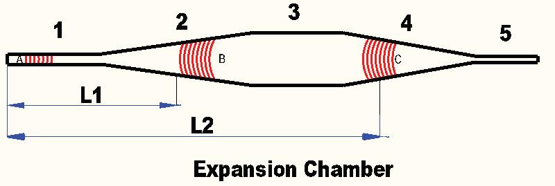
When the piston opens the exhaust port there is a rapid expansion of the combustion gasses which sends a positive shock wave (A) off down the pipe (much faster than the exhaust gas) which when it reaches the diverging cone, a portion is reflected back as a negative pulse (B). If the length from the port to the cone (L1) is correctly chosen that negative shock wave arrives back at the exhaust port while it is still open and helps pull the burnt gasses out of the cylinder (“scavenging”). What’s left of the original shock wave continues down the pipe and arrives at the converging cone to be reflected back as a positive shock wave (C) which, again if the length (L2) is correct, helps push escaping fresh air/fuel mixture back into the cylinder just before the piston closes the exhaust port (“charging”). If that returning shock wave is sufficiently strong and accurately timed (difficult because the speed of sound changes with exhaust temperature) it is capable of increasing the charge pressure in the combustion chamber, in a similar way to a turbo or supercharger…driving Brake Mean Effective Pressure (BMEP) and thermal efficiency.
Hopefully, I have explained this satisfactorily, for the second time!! So, how did I improve on this magic resonant device? As explained above, if the positive shock wave is properly organized to arrive back at the exhaust port at the correct time, a kind of supercharging effect occurs, raising the engine’s BMEP and thus power (as well as shoving escaping fresh charge back into the cylinder, reducing unburnt hydrocarbons…a good thing for the environment). The problem is in the timing. The shock wave travels at the speed of sound (fixed once the system settles down at a constant operating temperature) but the port opening timing changes with the speed of the engine. The higher the crankshaft RPM the shorter the pipe needs to be to get the shock wave to arrive back at the port at the right time. Expansion chambers conventionally use a converging cone to send a series of shock waves back to the exhaust port, effectively allowing the increase in charge pressure to be spread over a range of engine speeds (so L2 is actually a series of effective lengths ranging from L2a to L2n). The downside of this configuration is that the peak pressure is reduced because the total shock wave energy is reflected back over the length of the cone rather than a single hit.
This leads to one of the primary compromises that must be made when designing an expansion chamber: the angle of the converging cone. Steeper angles return bigger power (due to increased BMEP) but with a narrow power band (hence the peaky response of two-stroke race bikes…in the early days some incorporated up to fourteen speed gearboxes to keep them “on song”). Shallow converging sections offer broader power bands but with less impressive peak numbers.
What I came up with was an actively adjustable rear cone.
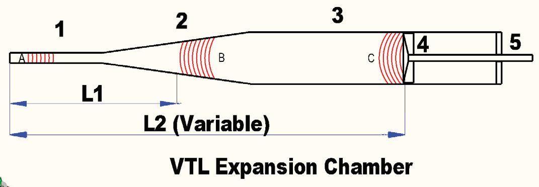
Extremely steep angle, almost flat, and perpendicular to the shock wave, the only shape being configured to aid the escaping exhaust gasses outflow unimpeded. The trick was that the flat plate was dynamically located axially in the straight chamber by an electric drive motor, constantly changing the effective tuned length of the exhaust in response to engine speed (∞L2). Figure 2 illustrates the configuration (without actuator and sensor details) of this Variable Tuned Length Expansion Chamber (“VTL” for short). It is similar to the conventional configuration illustrated in Figure 1 other than the converging cone (4) has been replaced by a moving plate (4).
Figure 3 shows the engine (a 1980 Suzuki 125cc air cooled piece from an RM dirt bike of the period, this being just at the edge of liquid cooling, something that would have made my life a lot easier on the dyno) with the complete experimental pipe on the test “bench”.
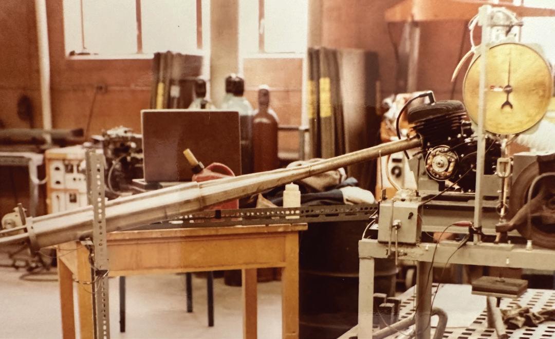
The control was fully analogue using an array of resistors to square up the voltages generated by a rotary potentiometer on the “pipe’s” moving element and a tachogenerator driven off the crankshaft. A voltage comparator and op-amp circuit provided a voltage to the moving element’s drive motor, constantly trying to keep the “error signal” (the difference in the measured voltages) at zero. Those that have any knowledge of PID controllers will detect that I did not at that time. A simple dead-band stopped the system from wearing itself out as it tended to be constantly moving, a very busy test rig when working the throttle!
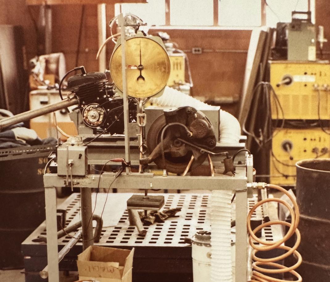
I built a dyno (Figure 4) out of an old Chevrolet Impala spindle, brake rotor and caliper with a master cylinder modified so as to be actuated by a screw thread. A purloined Salter scale was used to measure the generated force at the end of the steering arm and a programmed equation in my TI calculator (I forget the model, because we were all buying the latest version every two months… unless you were one of those weird HP guys…RPN) which spit out the crankshaft torque value for a given constant (relatively) speed at the same location (ignoring losses). All that being analogous to simultaneously spinning six plates while riding a unicycle, as the brake faded almost faster than the master cylinder could be dialed in while the throttle was slowly opened to 100 percent. At steady state (all plates spinning) the moving element of the “pipe” settled down and a power reading could be taken. The final missing piece of data being the crank speed which was measured using a handheld tachometer that had a rubber wheel held to the crank extension (the tachogenerator was only ever a voltage). Everything was cooled (engine, Impala brake rotor and all the other hot stuff) by shop air distributed via copper pipes with squished ends. When running at full bore it was truly frightening. I once tried it on my own, late at night when nobody was there to help, or get hurt, and it didn’t go so well. But we only ever had one serious runaway when the master cylinder shit a seal. I calmly got it shut down (didn’t want to freak the supervising professor out, I was actually terrified) but it got some discussions going in the faculty about letting guys like me loose in the labs.
The bottom line was it made just over three more horsepower than the stock set-up, which showed as 21 on my dyno, Suzuki claimed 27 peak in the brochure, but that was at the crank with the production expansion chamber, whereas my raw torque was at the “dyno shaft” (which included gearbox losses, the dyno chain drive and the ’72 Impala spindle assembly), using the “test exhaust” with a fabricated diverging cone inside it. More impressively it returned the peak over a powerband almost 1000 rpm wider than stock. It worked! Just needed some refinement and a bit of help with the manufacturing engineering.
I figured Suzuki would jump all over the concept (they were sponsoring it) but other than complimenting me on the quality of the thesis report (my mother typed it for me on a very early word processor) they never actually made comment on the veracity of the invention. I kept the engine and made a road racing bike out of it with another concept that I called the “suspension module” in the rear, the spring and shock being driven by cams (for another time).
The bike never actually got past a ride down the street where the engine finally succumbed to all the abuse I had inflicted upon it during my testing. As happens, more often than not, right around the time of my development work a host of active two-stroke exhaust technol- ogies started to bleed into the market. I had conceived the idea of a VTL Expansion Chamber in around 1980 without any prompting from similar technologies (I wasn’t big on state-of-the-art research, more on making stuff and testing it). But when I was proudly finishing things up, a load of novel power enhancing two-stroke exhaust related gimmicks (that is unkind, it was all really clever) hit the market: Honda ATAC (1984 Honda CR125) and Yamaha YPVS (1983 RD350LC… but earlier on the TZ race bikes). The former trying to achieve a similar outcome as me by changing the overall volume of the exhaust using a switchable chamber in the cylinder casing, and the latter being different in that is altered the exhaust port shape/timing. All this technology was ultimately gathered up under the terminology “Power Valves.” I messed with them incessantly on Artic Cat 440 race sleds many years after my foray into inventing such devices.
What did I learn from this highly satisfying technical exercise, undertaken in my last couple of years at Ryerson? Two things: don’t assume that everybody is going to “get it”, and technology moves fast, so if you snooze you lose. I’ve run a little over on this topic and will keep the Supermilage/Fuelathon engine story for another time… not so much novel, but an impressive interpretation of the rules that resulted in a highly innovative, and successful, hybrid engine. Not in the modern sense of that terminology but referring to the cross breeding of a Briggs & Stratton side valve utility piece (dictated by the rules), with a venerable overhead cam Honda 50, and some additional bits from a Fiat 131, Husqvarna chain saw and Hodaka Super Rat dirt bike. Finished second in a field of almost one hundred University’s competing that year. IT


