30 minute read
Engineering Projects
AN INNOVATIVE APPROACH
Portsmouth Water and Southern Water are collaborating on an innovative approach to secure longterm resilient water resources for the South East of England - a new way of working that provides a blueprint for future planning.
Advertisement
Together, the companies are developing Havant Thicket Reservoir in Portsmouth Water’s supply area, to enable reliable supplies for Southern Water’s customers in Hampshire.
It will be the first new reservoir to be developed in the UK since the 1980s and will play a key role in reducing abstraction from the region’s internationally-renowned chalk streams, the Rivers Itchen and Test.
It will also be the first time a significant water supply asset has been developed in this way, in one water company’s supply area to share supplies with another company’s customers - potentially establishing a precedent for others to follow.
Taking a regional view
The Government is currently calling for water companies to invest in more resilience projects to help supply water, such as reservoirs and regional transfers. Projects like this are needed to secure reliable water supplies for the future, alongside reducing the amount of water lost through leaks and encouraging people to use less water.
This will help the country tackle extremes in weather such as droughts, which are likely to happen more often and be more serious, as our climate changes. It will also help provide water supplies to more customers in the future as the population grows in the UK and enable water companies to leave more water in the environment to support habitats and wildlife.
Havant Thicket Reservoir has been enabled through the regional strategy of the Water Resources South East (WRSE) group, which includes six water companies in the region and their regulators. It marks the success of moving towards strengthened regional planning to identify the best value schemes to increase resilience and deliver environmental improvements.
Portsmouth Water will construct the reservoir in its supply area so it is operational by 2029. Further investigations are also underway as part of the RAPID programme and WRMP 24 planning to explore if the reservoir could play an even greater role in supporting resilience in the future, through new transfers and as a conduit for recycled or desalinated water.
Portsmouth Water and Southern Water have now signed an 80-year Bulk Supply Agreement, under which Portsmouth Water will supply 21 million litres a day to Southern Water, up to a 1 in 200-year drought - an arrangement made possible by Havant Thicket Reservoir being in place.
FEATURE: ENGINEERING PROJECTS
The need for the reservoir
The South East of England, as a whole, is under ‘serious water stress’ and water companies are being asked to take less water from some of their sources - such as the chalk streams and rivers in Hampshire - to keep them healthy and protect wildlife.
At the same time, water companies need to find more water to cater for the effects of climate change and a growing population. This major change is going to particularly affect Southern Water, which needs to find new water resources for the customers it supplies drinking water to in Hampshire, to replace water taken currently from the River Test and the River Itchen.
Portsmouth Water is in a better position, as its supply area is only under ‘moderate water stress’.
This is because there are underground springs which provide plentiful, clean water. In winter, much of this water is surplus to Portsmouth Water’s requirements and flows out to sea, so much better use could be made of some of the water by capturing it and storing it in the reservoir until it’s needed.
This would allow Portsmouth Water to share more water from its network with Southern Water’s customers in Hampshire and increase the resilience of water supplies in the South East. ■ Portsmouth Water already has agreements to share up to 30 million litres of water a day with Southern Water (in West Sussex and Hampshire) ■ It can share a further nine million litres a day from 2024 from other sources (Hampshire) ■ It can provide an extra transfer from a mix of sources when the reservoir is built - 21 million litres of water a day (to Hampshire) ■ The total would be up to 60 million litres of water per day provided by Portsmouth
Water to Southern Water.
Overall, building Havant Thicket Reservoir would make the whole of the South East of England much more resilient to droughts, which are likely to happen more often in the future due to climate change.
Meeting future challenges
Portsmouth Water first received planning permission for Havant Thicket Reservoir back in 1964 and it carried out a lot of work towards a new planning application in 2008. However, at the time there wasn’t enough demand for the water, either from Portsmouth Water’s customers or across the South East.
Since then, Southern Water has agreed to reduce the amount of water it takes from the rivers Test and Itchen in Hampshire, to protect the environment, so they need to find new sources.
Portsmouth Water is now working in partnership with Southern Water to go ahead with the reservoir to secure more reliable water supplies for the region as a whole.
Havant Thicket Reservoir will also provide a new green leisure hub for communities close to the site, who are both customers of Portsmouth Water (drinking water) and Southern Water (wastewater), promoting better health and wellbeing in a neighbourhood which is among one of the most deprived in Hampshire.
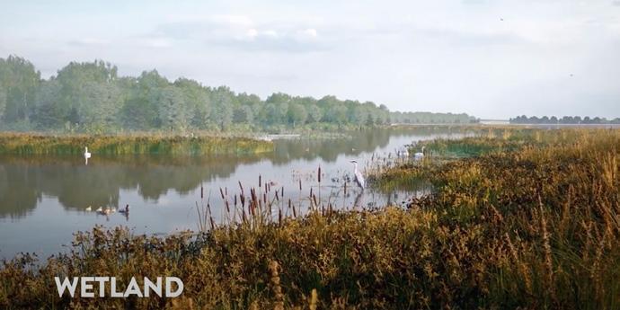
The development of the project would also include the creation and improvement of a minimum of 110 hectares of woodland and pasture, both on and close to the reservoir site, to create new habitats and corridors for wildlife. A new 10-hectare wetland would also be created on the northern shore of the reservoir and a long-term grant scheme would be established to support environmental projects in the local area.
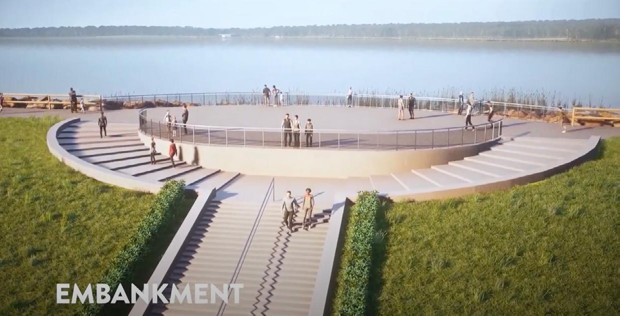
Projected timeline for Havant Thicket Reservoir
Portsmouth Water submitted planning applications for Havant Thicket Reservoir in late 2020, with a decision on granting planning permission expected in Spring 2021. Subject to the planning applications being approved, below is a timetable for how the reservoir scheme would progress through to completion in 2029.
2021-2022:
■ Ongoing creation of new woodlands and habitats for wildlife migration ■ Prepare planning applications for the detailed design of the reservoir operational and visitor ■ facilities, access and recreational routes and reservoir pipeline route ■ Build the access roads ■ Start work to prepare the reservoir site ■ Divert paths ■ Community engagement.
2023-2026:
■ Dig out the clay on site and move it to shape the reservoir bowl ■ Build the reservoir embankment ■ Lay the reservoir pipeline which will transfer the water from the springs to the reservoir ■ Community engagement.
2027-2029:
■ Create a new network of paths ■ Pump water from the springs to fill the reservoir (during winter) ■ Build the visitors’ centre and other facilities ■ Open to the public.
Further information
For more on Havant Thicket Reservoir and Portsmouth Water and Southern Water’s innovative collaboration to secure future water resources, please visit:
www.portsmouthwater.co.uk/havant-
thicket-reservoir or www.southernwater. co.uk/water-for-life-hampshire.
STORMHARVESTER
AI SUCCESSFULLY DETECTS BLOCKAGE FORMATIONS FOR WESSEX WATER
Rainy day in Bath – hyperlocal rainfall was a major input into creating dynamic thresholds used to achieve such accurate forecasting.

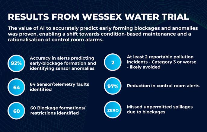
Machine-learning technology trialled on part of Wessex Water’s sewerage network has identified early forming sewer blockages in real-time with a 92% accuracy rate, whilst enabling an operational shift to condition-based maintenance.

by Brian Moloney
Managing director, StormHarvester
The potential of artificial technology (AI) to transform sewer network management has been demonstrated during a threemonth trial of StormHarvester’s Intelligent Sewer Suite with Wessex Water in the city of Bath, Somerset. The technology quickly demonstrated its value, with over 60 early blockage formations detected in real-time and control room alerts reduced by a staggering 97 per cent.
Managing sewer blockages represents a significant operational challenge for water and wastewater utilities. As well as problems arising from the blockages themselves, heavy rainfall often triggers hundreds of alarms because of high levels within the sewer network caused by runoff. The volume of these alarms during wet weather can be overwhelming for operational and maintenance teams.
The incumbent system operating in the Wessex Water control room generated some 4,500 alarms during the trial period, yet StormHarvester’s Intelligent Sewer Suite (ISS) was able to mute alarms where high sewer levels were predicted by the AI software due to rainfall, reducing the total to 138, of which 124 were genuine blockage formations or sensor faults. This gave the utility’s crews capacity to respond rapidly to each alarm.
The trial took place from June to August 2020 in the wastewater catchment of Bath, which comprises 3,500km of sewerage, representing 10% of Wessex’s total. ISS was applied to an array of 98 level sensors already present in the network - 89 at combined sewer overflow – CSO - sites and the remainder at pumping lift stations.
Machine-learning
ISS uses machine-learning, an AI application that enables systems to automatically learn and improve from experience without being explicitly programmed to do so. The StormHarvester system’s smart machinelearning algorithms and predictive analysis tools were applied to catchment sensor data
and corresponding hyperlocal rain forecasts to predict the wastewater flow levels and detect potential early blockage formations in real-time.
Wessex Water wanted to test the ability of machine-learning to: ■ Predict blockage formations in sewer pipes and pumping stations early and intervene before they became service failures ■ Better separate genuine control room alarms from alarms triggered because of high volume rainfall during wet weather ■ Dramatically improve the response time to service failures
ISS took only three weeks to set-up before it started providing usable results. Safe operating windows for assets in the network were predicated based on factors including time-of-day, day-of-week, rainfall and river levels. These dynamic thresholds are predicted for six hours into the future and are updated every 15 minutes, at asset level, which is one of the keys to such accurate forecasting.
Edmund Willatts, asset reliability engineer, Wessex Water said, “The StormHarvester system used machinelearning to set safe operating windows or thresholds for each asset. Each time these had a significant breach, we received alerts, which in turn were passed to the operations team so that they could respond.”
Pollution reduction
The Environment Agency is seeking a zero level of pollution incidents for the water industry in England and puts incidents into four categories, with Category 4 being the least serious and having no impact on company performance. Category 3 incidents can impact on performance commitments and risk breaches of environmental protection and water industry legislation. They can also lead to significant costs, including emergency response charges and penalties from regulators.
Results from the trial showed significant alarm rationalisation and a high degree of accuracy in blockage detection. Over 60 early blockage formations were detected, at least two of which were likely to have caused pollution incidents – Environment Agency Category 3 or worse. Over 60 telemetry and sensor faults were also detected.
FEATURE: ENGINEERING PROJECTS
Jody Knight, asset technology manager at Wessex Water said, “The StormHarvester team identified sewer blockages that using our normal working processes we may not have spotted until they had resulted in unwanted sewer overflow events.”
Wessex Water considered the alerts provided by StormHarvester to be a major improvement on the status quo, where operational staff were regularly overwhelmed by the large number of high-level and overflow alarms occurring during periods of heavy rainfall. It also makes the potential for predictive maintenance very realistic in the near future.
Willatts said, “This condition-based sewer maintenance versus the scheduled cleaning regime will be key to making operational teams more productive and efficient going forward.”
Multiple capabilities
The Wessex pilot revealed that StormHarvester technology has the capability for: ■ High blockage prediction accuracy – 92% of alerts were relevant and required and not a single blockage resulting in a pollution incident was missed ■ Few false positives – 8% of alerts were false positives ■ Long-range blockage prediction - early blockage formations identified up to eight weeks before they would have resulted in service failures ■ Condition-based maintenance - the three-month trial has enabled a shift in approach. ■ Control room alarm rationalisation - a 97% reduction in control room alerts was achieved versus business as usual
Knight said, “One of the biggest problems we have serving our customers is not knowing where and when blockages will occur, or are likely to occur, in the wastewater network. During the three-month trial, StormHarvester identified at least two incidents that we are fairly confident would have resulted in Category 3 spillages, or worse, if it was not for the early blockage detection alerts received and the subsequent action taken by Wessex operational staff.”
Neil Macdonald, co-founder of StormHarvester said, “Wessex Water have been great to work with and this trial has proven that Intelligent Sewer Suite is effective at scale. Our technology proves that predictive maintenance is possible, representing a significant increase in the available time for operational crews to recover and repair assets.”
Based on the value brought by the StormHarvester alerts during the proof-ofconcept trial, Wessex Water has maintained the solution running on the Bath wastewater catchment into 2021.
Brian Moloney is hosting two roundtables at the SWAN 11th Annual Conference, which takes place online 24-28 May, visit www.swan-2021.com
www.stormharvester.com
Z-TECH
HAZARDOUS AREA TEST AND INSPECTION – WHERE IS START!
Z-Tech have been working to maintain Hazardous Area compliance, on customer sites, for over 10 years. The following is an insight into how an inspection schedule can be managed to compliance under the BS60079 legislation, and help assist you to managing your approach – particularly under current pressures.
Before we go into too much detail on inspection schedules and the factors that should be considered, it’s important to remember the initial inspection stage, without this the equipment should not be brought into service. Often we advise on the best way to carry out periodic inspections of a hazardous area installation: the problem occurs when we ask to see the initial inspections, the equipment register or current inspection strategy, more often than not the records have been misplaced or archived somewhere with the rest of the project documentation. Sometimes there was not an initial inspection carried out, and no verification dossier was produced for the installation.
There are essentially 10 steps to achieving a compliant hazardous area inspection schedule and it starts with the conception of the project: 1. The design 2. The installation 3. The hand over 4. Implementation of inspection strategy 5. First sample inspection 6. First periodic inspection 7. Review of inspection results, 8. Assessment of inspection strategy 9. Implementation of amended inspection strategy 10. Periodic inspection with a detailed sample 11. Repeat steps 7, 8, 9 and 10 for the life of the installation.
Some of our ‘tips’ looking at 6 of these steps: 1) The design
Often during the design stage all equipment is selected correctly, but in many cases, a lack of thought is given to the first principle of managing a hazardous area – ‘does the equipment need to be in the area or can it be located away from the hazardous area OR do we really need it?’ Use small remote pumping stations as an example: unmanned 90% of the year with visits for basic maintenance of equipment and inspection only, commonly these sites will still have lighting installed, where with properly documented access procedures, portable lighting would totally eliminate the need for fixed lighting. If this is taken into account at the design stage, then there is significant financial benefit not only from the reduced installation costs but also from the ongoing benefit of a reduced number of inspections having both management and inspection costs associated with them, this also eliminates the risk to the maintenance teams.
2) The installation
In the installation and commissioning process, initial inspections are to be carried out at this point of the equipment life cycle, timing is crucial as these must be done before power is applied to circuits and live commissioning.
This initial inspection can be utilised by the project documentation team, as an opportunity to identify missing documentation and the accuracy of the asset register compiled as part of the verification dossier for the installation. It is important at this point to remember that equipment will be maintained during the commissioning process and while the initial inspections have been completed, it is worth a complete close inspection of all equipment to check that no external faults have been introduced to the installation. This will have an initial financial cost but hugely increase confidence in the compliance of the installation, some of the most common faults are seen where the inspections carried out after commissioning are missing or loose enclosure bolts and covers, this causes issues with both the certification of the equipment and the safety of the installation, but is often forgotten in the pressure of meeting final project deadlines. If this additional verification of the installation is carried out, then it can pay back very quickly by reducing the number of failures picked up at the first sample or periodic inspection.
3) The hand over
This is the stage where most missing documentation or inspection records can be traced back to. The process at this point should be no different for internal or externally delivery installations. In hand over you should be provided with a verification dossier as per BS60079-14.
FEATURE: ENGINEERING PROJECTS
One of the most common mistakes that is made here is not incorporating this information into the document management system that is being operated within your organisation. This verification dossier is a live document and without maintenance of the information it is easy to introduce non-conformances.
For example, updating the equipment register to reflect a change in ‘make and model’ of equipment, or updating the descriptive system documents to reflect changes to intrinsically safe systems. The retrospective compilation of the verification dossier will cost substantially more and consume a vast resource especially in the case of hard to access equipment or IS systems where calculations must be redone.
4) Implementation of an inspection strategy
This can be one of the hardest things to settle on but it is key to ensuring compliance of the installation, so what should be considered? ■ The environment: is the equipment outside, is there a high level of UV radiation, are the substances in the process likely to cause an increased rate of corrosion? ■ The Zone or EPL: you may wish to inspect equipment in Zone 1 more frequently than Zone 2 ■ Type of plant: what is the perceived risk level of ignition, taking into account persons exposed, environmental pollution and financial implications. Guidance on this can be found in RG101 published by
UKAS ■ Frequency and quality of maintenance: does the equipment require regular calibration? ■ Susceptibility to damage: if the item is in a high traffic area where it is likely to be impacted then you may want to inspect more frequently
Once you have decided on the provisional periodic inspection interval, it is important to document the justifications and considerations, as this will be a key part of transferring responsibility should the responsible person change.
Alongside the definition of an inspection interval, you will also need to decide on a sample size, good guidance on the calculation of sample sizing can be found in the Guidelines for managing inspection of Ex electrical equipment, ignition risk in support of IEC 60079-17 published by the Energy Institute, and key performance indicators linked to the results of inspection should also be set.
5) The first sample inspection
This is going to be the inspection that confirms or indicates the need for a variation from your inspection interval that is implemented in your inspection strategy. At this point BS60079-17 suggests that a sample inspection at a close grade is carried out, this should be after a time period that allows the plants operation and environmental conditions to take effect but not your full inspection interval, so if you have decided on a 24-month inspection interval a sample at 12 months should give a good indication of the suitability of the interval.
The results of this sample should be compared to the KPI’s that you have been set out in your inspection strategy, ensuring that the time period is taken into account, if you have set out that a 20% failure rate is acceptable over 24 months you would not expect to see more than 7-8% at the 12-month mark. Using this information and by analysing the type of faults you should either confirm or modify your inspection interval to suit.
6) The first periodic inspection
This is going to be your first idea of the full condition of the plant. Following the guidance of BS60079-17 this should be a close inspection of all equipment with a sample as defined in your inspection strategy at detailed grade. As per you first sample inspection you should review this against the KPI’s in your inspection strategy and assess whether a modification to the inspection period and sample size is required.
This process of inspection and review can then be carried out for the life of the plant, ensuring that any justification to the inspection strategy is documented and recorded.
Should you be fortunate enough that a justifiable increase of the inspection interval to 3 years has been achieved, you are still finding low levels of failure and can justify a change to the inspection strategy, then you can look to move to a visual inspection of all non-ignition capable equipment and close inspection of ignition capable equipment. It is vital to keep your detailed sample as this will fulfil the requirement under BS60079-17 for equipment to be subjected to inspection of internal and external components throughout it its life cycle.
It is important to remember that when looking at inspection results different areas of plant can be inspected at different intervals based on location of installation, likely hood of mechanical impact, frequency of maintenance. An example of this would be a junction box that is on a wall 20ft up will be less likely to become damaged than a low level transducer that is calibrated every 6 months and therefore would require less frequent inspection from a risk based point of view.
Any increase of the inspection interval after this point will need justification by a specific safety assessment carried out by an expert, this would involve looking into the environment, operation and manufacturers guidelines for maintenance of the asset.
To summarise there are a few key points that you will have noticed throughout: ■ Don’t rush it, in a world where economics drive so much of the way we work and operate it may be tempting to allow the pressure budgetary requirements to lean you towards prematurely increasing inspection intervals, but this will not demonstrate a risk based approach to inspection and ultimately not satisfy the questions raised in the event of an ignition. ■ Document everything, if all modifications to plant are assessed and documented then you will have an accurate verification dossier that will allow you to make clearer decisions around your justifications and be able to demonstrate competence to an auditor. ■ Plan to leave, sounds like an odd one but if you make your records clear so that anyone can pick it up your life will be easier. ■ The better your inspection and maintenance records the easier to justify an increase in inspection interval and therefore more financial benefit.
Finally, bring in the experts as it will make your life a lot easier and help to reduce your own personal risk if things go wrong, but knowing the basic principles helps you become an intelligent customer.
SUFFOLK TREATMENT WORKS INVESTMENT TO PROVIDE A LONG-LASTING LEGACY TO THE ENVIRONMENT
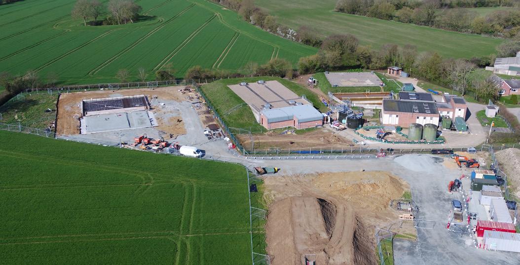
The drone photo taken on the 8th of March 2019, just 12 working days after breaking ground on site, the progress includes time spent setting up the welfare facilities.
An existing water treatment works (WTW) in the Suffolk countryside has benefited from a £7m upgrade to increase supply resilience to both its residential and commercial customers in the area. The project needed to deliver a new treatment stream capable of treating the site’s abstraction license within an 18-month timeframe.
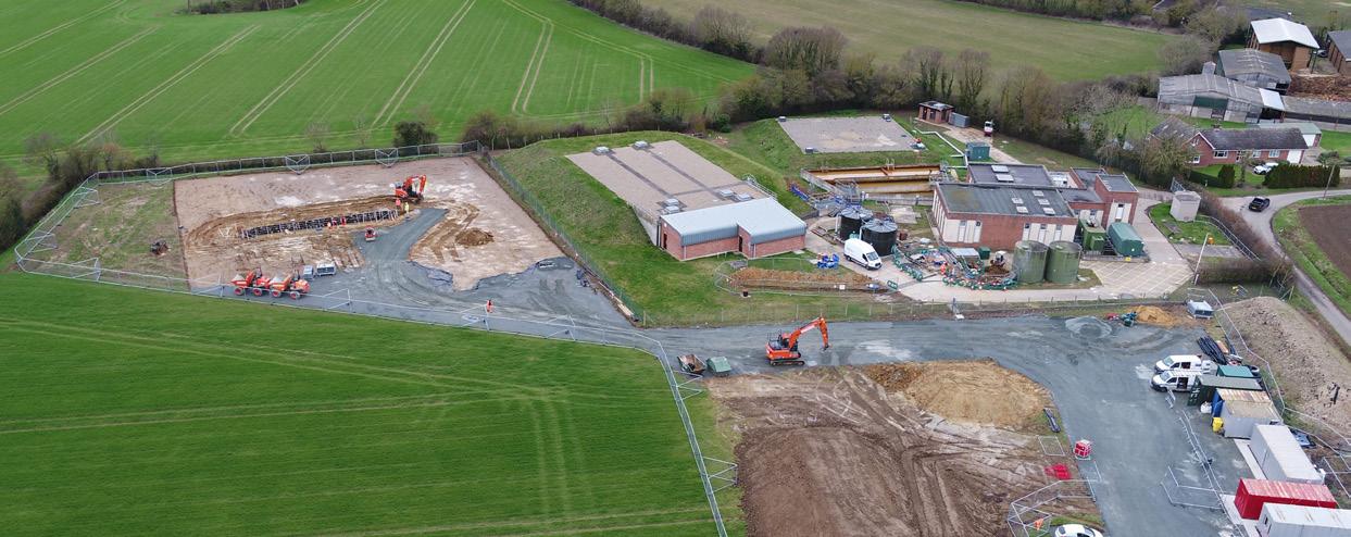
Hartismere Water Treatment Works (WTW) is located in the Suffolk region. To ensure it could treat its full abstraction licence of 7.8Ml/d, Essex & Suffolk Water needed to upgrade both the treatment works and local network.
The £7m investment project delivered a new treatment stream capable of processing the site’s abstraction license, within a tight 18 month timeframe, to provide a resilient supply to both its residential and commercial customers in the area.
The project scope was focused on the following key areas: ■ Purchase land adjoining the existing site ■ Construction of a new filter building ■ New primary pressure filters ■ New secondary filters ■ Cascade aeration tanks ■ Primary wash tank ■ Secondary back wash tank ■ Chlorine reaction vessel ■ Chlorination upgrade to include a provision to comply with Reg. 26 ■ Motor Control Centre (MCC) ■ Coagulation dosing plant ■ Back wash settlement tank ■ Interface with existing assets ■ Demolition of redundant assets
Essex & Suffolk Water’s engineers were able to base the design of the new treatment stream on a similar upgrade at its Halesworth WTW on the Suffolk coast. Utilising designs from the Halesworth WTWs enabled engineers to keep within time constraints and to reduce project risks. A design envelope was produced by process design engineers which steered the project team to the key parameters that were needed.
When developing plans for future WTWs upgrades, NWG will now use the success of Hartismere WTW as a benchmark.
The total project budget was £7.218m and had a projected time scale of 18 months. However, the project was delivered in 10
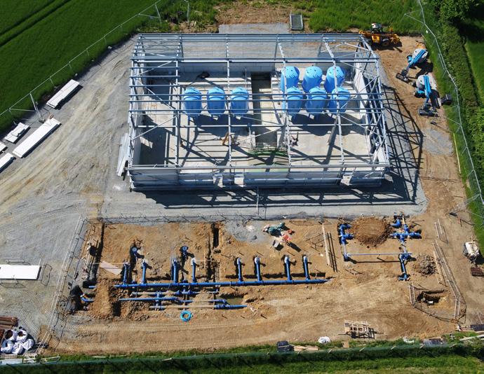
Base progress made in 28 days. Taken on the 1st of April 2019.
FEATURE: ENGINEERING PROJECTS
months having mobilised to site in February 2019 with final commissioning taking place on 17 December 2019. Considering the scale and complexity of the project, this was a great achievement. Further commissioning on three bore sources all with varying levels of iron and ammonia (naturally occurring in the groundwater aquifer) took place between 6 January and 16 March 2020. The time constrained programme was a key challenge and the project team used a variety of tools to achieve the 18-month target, including a design sprint.
The original scope of the project was to utilise the existing secondary filters at Hartismere. However, the condition and viability of utilising these filters was unknown and was considered a significant project risk. During the investigate and define phase of the project, it became clear connecting the new primary and secondary filters would be extremely complex, high risk and costly. However, within the original budget, the project team were able to provide a new two-stage filtration process. Using a 4D model enabled project managers to walk round the site and allowed them to make changes early so that there was no need for re-work in the project. This meant being able to embrace off-site build techniques.
Engaging with all stakeholders was a crucial element of the project. Customers View of the new building and area for the tanks, progress achieved in 98 days.
were invited to consultation meetings and received regular updates.
An innovative stakeholder design sprint took place with all key stakeholders to understand the need and expectation of the project. A one-day event, adopting the principles of a five-day sprint took place followed by a scope freeze sprint, to present the revised design solution. This project will ensure that Essex & Suffolk Water is able to treat its full site abstraction licence daily and annual licensed quantities. This investment has delivered a reliable and resilient treatment works and provides a lasting legacy for Essex & Suffolk Water customers. Part of this legacy is an accessible public footpath that was installed around the local meadow for residents to use.
THE REVIVAL OF TERTIARY CONTINUOUS FILTERS
Tightening effluent consents due to river water quality drivers require further investment for improved removal of nitrogen and phosphorus from Wastewater Treatment Plants (WwTP). As a result, tertiary treatment processes have become increasingly important.
by H Wouters
Brightwork, the Netherlands
G Medley and R Matthews
Dŵr Cymru Welsh Water, United
Kingdom
This has led to a need to gain a better understanding of the process and mechanics of tertiary removal systems in order to remain both compliant now, and for the future lowering of effluent discharge limits.
Efforts have been successfully made to upgrade and refurbish existing tertiary continuous sand filters using the novel Sand-Cycle technology. It has given rise to a better understanding of the relationship between sand circulation and filtration efficiencies. Real-time information acts as an early warning system to consistently meet better effluent qualities through faster reactive measures, as well as proactive analysis of data.
Phosphorus removal in existing treatment plants
Meeting annual rolling average total-P levels of 0.25 - 0.50 mg/l may require a primary, secondary and/or tertiary dosing of coagulant. Tertiary sand filtration with inline flow controlled coagulant dosing has proven effective to minimize coagulant dosage and meet residual Fe concentration limits (Wouters, 2018).
80% of DCWW sites are small WwTPs: capacities below 2,000 population equivalent. It is a challenge to manage these plants across a wide and varied geographical area. Additionally, these existing assets are challenged to meet more stringent effluent targets. With operational staff numbers reduced and more process complexity in the treatment process, this paradigm requires a significant shift in monitoring and control strategies. Remote sensing, expert judgement, and big data analytics are key to support asset optimization.
This is illustrated for two recently upgraded tertiary continuous filter plants within DCWW.
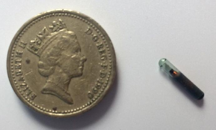
Figure 1 – RFID tag displayed
Monitoring and control of continuous sand filters
Continuous sand filtration, with uninterrupted filtration and continuous media washing, is widely applied in water and wastewater treatment. Various types and makes of continuous filters are used for tertiary treatment of municipal wastewater. Key features are the homogeneous sand circulation over the full filter area and the simultaneous continuous sand washing.
The actual sand circulation rate affects the filtration efficiency for both solids removal and biological conversion. Real time monitoring and control of sand circulation rates is therefore crucial to optimize plant performance and reduce down-time. passive RFID tags are applied (Figure 1). RFID tagging is an ID system that uses small radio frequency identification devices for identification and tracking purposes. It includes the tag itself (transponder), a reader and a host system application for data collection, logging, processing, and transmission. The RFID tag is briefly activated by the radio frequency scan of the reader.
Each transponder has a unique code, which cannot be duplicated. Although RFID tagging is used in many applications, such as tracking wildlife and livestock, the use in the water industry is new, creating powerful opportunities in a fluidic environment.
Each transponder is detected while passing the reader, which is integrated in the airlift of the sand filter. The codes, dates and times of the passing transponders are transmitted via a decoder onto the datalogger, transmitting the data to the back end of the online data server. This server is converting the raw field data into relevant output data, using dedicated algorithms. Output is available for the
FEATURE: ENGINEERING PROJECTS
operators 24/7 via the data server front office, presented in dashboards.
Full scale value
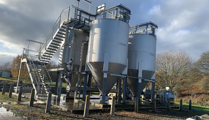
In 2020 two DCWW tertiary filter plants have been equipped with Sand-Cycle. At Whitchurch four continuous filters (make Colloide, figure 2) have been installed with Sand-Cycle following a successful innovation trial on a single filter in 2018, after which a focused refurbishment took place. From September 2020 onwards all units are operating consistently, meeting effluent targets without interventions.
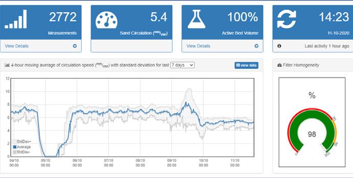
At Llanddewi Brefi WwTP a single continuous filter has been taken in operation mid-2020, to meet the effluent criteria for iron, solids and phosphorus. The dashboards are showing stable operations under varying process conditions. Any offsets, e.g. an interrupted air supply, causing the sand circulation rate to drop, is immediately picked up and reported to the operator (figure 3). Hence adequate actions can be taken.
Boosting filtration performance
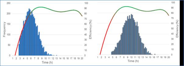
Continuous sand filters are often operated in non-optimal conditions, and hence its potential is not fully utilised. The key factor is the applied sand circulation rate. If the rate is too high the filter bed is in a “clean” status, similar to starting a conventional rapid gravity sand filter directly after a back wash. To use the full potential the pores should be partly filled with solids to enhance the filtration mechanism. In a continuous filter this is managed by controlling the air flow to the airlift, which determines the actual sand circulation rate.
This is illustrated in Figure 4. The lefthand diagram shows high sand cycle rates, corresponding with a bed turnover of 6 hours in average, causing the filter bed to be consistently too clean. In this operation mode no “solids” build-up is achieved in the filter bed. The right-hand diagram shows lower sand cycle rates (with a higher bed turnover of 10 hours in average), adjusted to obtain optimal filter efficiencies. Now, the build-up of solids in the filter bed is assisting solids removal. Hence higher filtration efficiencies and/or lower consent levels are achieved.
The combination of real time monitoring sand circulation rates and controlling the air flow has proven to be a powerful tool to stretch the operating window of continuous sand filters and gain the highest possible removal efficiencies.
Figure 2 – Tertiary filter plant at Whitchurch WwTP
Figure 3 Sand-Cycle dashboard (Llanddewi Brefi WwTP)
Figure 4 - Impact of sand bed turnover on filter performance (left Y-axis: frequency distribution of tags in blue bars; right Y-axis: filter efficiency in red-green line; X-axis: bed turnover in hours)
References
Wouters, J.W &. Agema. K.J, 2018. RFID technology as cost-effective real-time process monitoring and control tool in continuous sand filters: two case studies, the Netherlands: RFID technology as cost-effective real-time process monitoring and control tool in continuous sand filters: two case studies’ HIC 2018 – Palermo
Rathnaweera, S.S.; Rusten, B.; Manamperuma, L.D.; Gjevre, J.; Tranum, I., Evaluation of moving bed sand filter for denitrification, suspended solids removal and very low effluent total phosphorus concentrations, Water Science & Technology, 2019, p 232-242
BUSINESSCARDDIRECTORY
MaNuFacTuRERs & suppliERs OF valvEs, FiTTiNgs & siTE sOluTiONs FOR ThE uk & glOBal waTER, wasTE waTER & gas iNdusTRiEs
Northampton Office 8 Rushmills, Northampton, NN4 7YB, England T: +44 (0) 1604 601188
F: +44 (0) 1604 604818 E: customerservice@avkuk.co.uk www.avkuk.co.uk

Tel: 07884 004 802 E-mail: u.d.s@live.co.uk Web: utilitydesignservices.com Web: utilitydesignservices.co.uk
Proactive and professional civil engineering design consultancy services. We have extensive experience and expertise within the design of water network distribution & water network trunk mains. From initial overview through to detail civil design, while also equipped to provide planning, project management and construction support services. We would welcome the opportunity to visit you for an initial consultation to discuss your aims and needs. We would endeavour to incorporate our design and engineering solutions to match your business requirements. Surge control systems and compressed air engineering from Quantum Engineering
Developments Ltd



Tel: 01527 577888
www.surgevessels.co.uk
Windmill Insight Solutions
Tailored Training, Real Results
Quality Training for the Water Industry - Personalised for your people - Relaxed but thorough training - On site delivery - Discounts for ongoing contracts
Leadership and Management• Tailored L4 programmes• EUSR Training•
m: 07554 994855 e: bob@windmillinsights.co.uk www.windmillinsights.co.uk
SUMMER EDITION 2021 - PUBLISHING EARLY
JUNE
• Digital Transformation • Environmental Management • Groundwater • Wastewater Treatment Solutions
To advertise your company contact Martin Jameson on 07342 850289 or martin@jimjammedia.com
IN THIS ISSUE WATER QUALITY WATER RESOURCES C-MEX/ODI’S LEAKAGE INVESTIGATION TECHNIQUES ENGINEERING PROJECTS
INSTITUTE OF WATER MAGAZINE


