19 minute read
Floor


100mm PCC
3 Brick Thick Course
Advertisement
Queen Closer
100MM PCC
Natural Earth
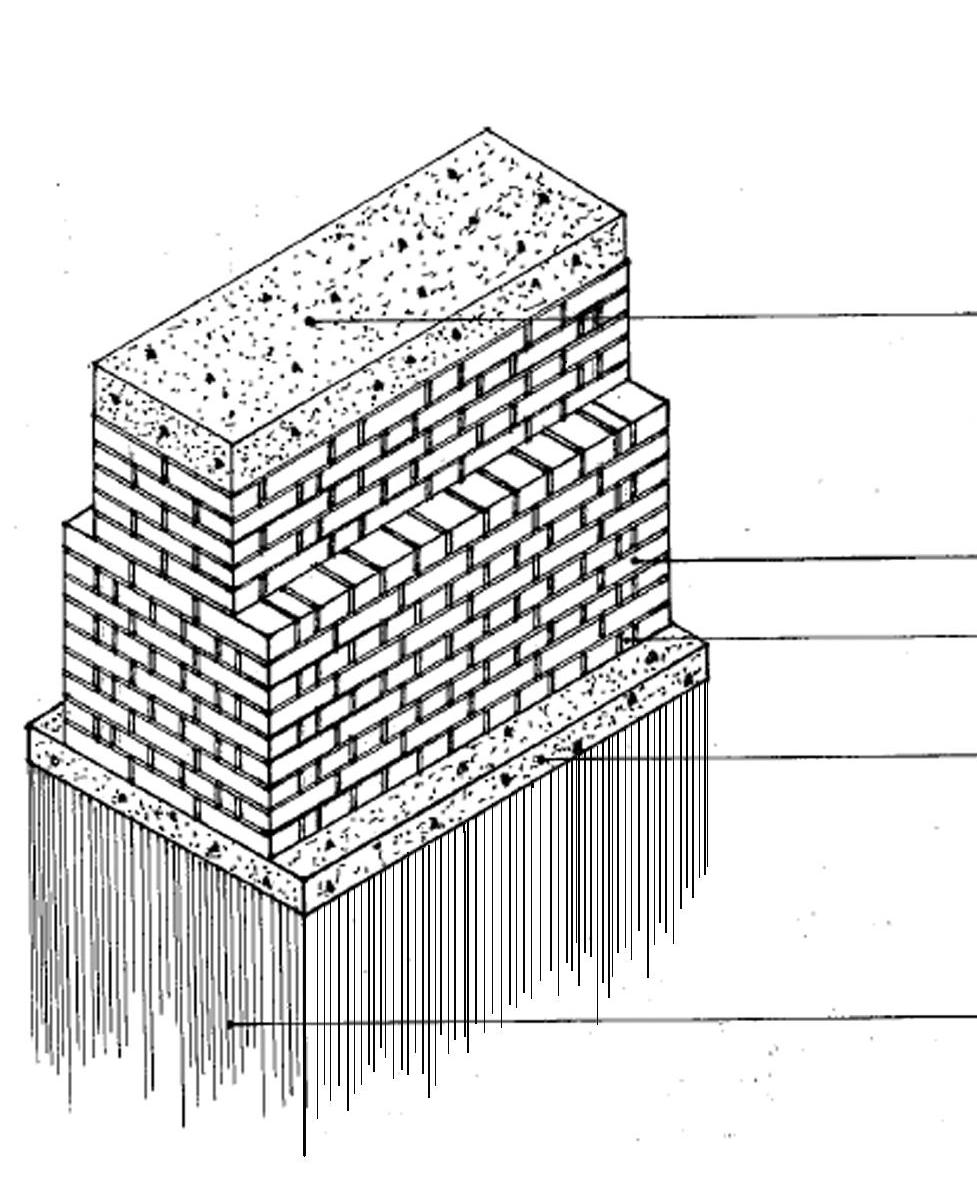
Isometric sketch of foundation
The above foundation detail consists of a 100mm thick P.C.C (Plain Concrete Cement) layer at the bottom. After which a 3 brick thick foundation, up to 9 courses is made.
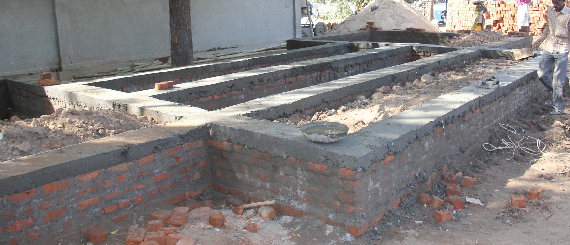
Plinth construction on site
Till the Natural Ground Level(NGL) the foundation is kept 3 brick thick. Then 5 courses(2 brick thick) are laid above the NGL, above which the 100 MM thick P.C.C bed is laid.
3.1 Back Filling
After the P.C.C bed, the remaining plinth was filled by the excavated sand. Once the plinth was filled, water was poured over the backfilled sand to allow it to settle.
Back filling at the plinth
Concrete Block
Concrete block in brick pier
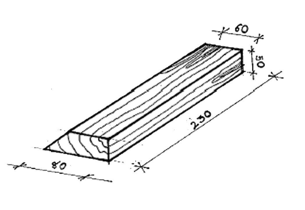
Exploded sketch of concrete block
The pre-cast concrete block shown in the above picture is used to hinge the door to the brick piers. Each of the pier consists of 2 concrete blocks. These blocks are only placed in the piers where the doors are to be hinged.
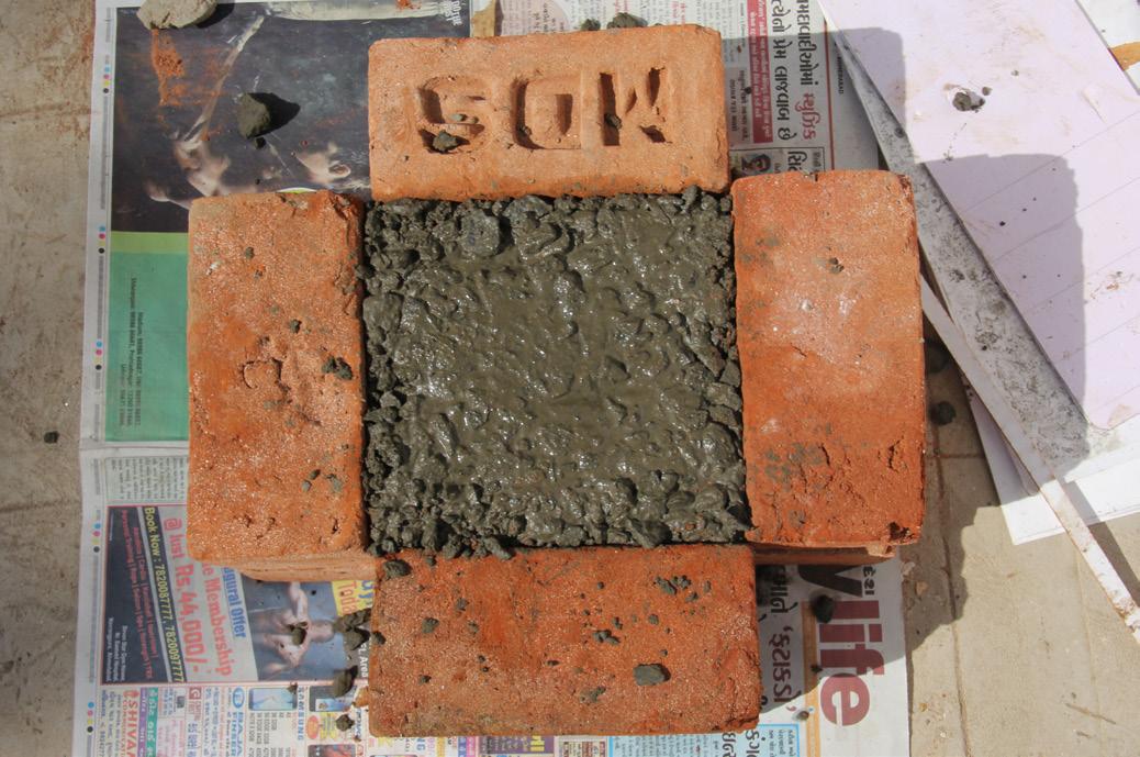
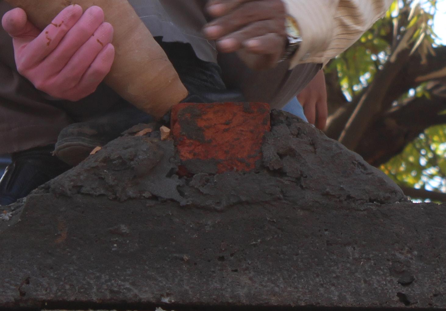
4.1 Making Of Concrete Block
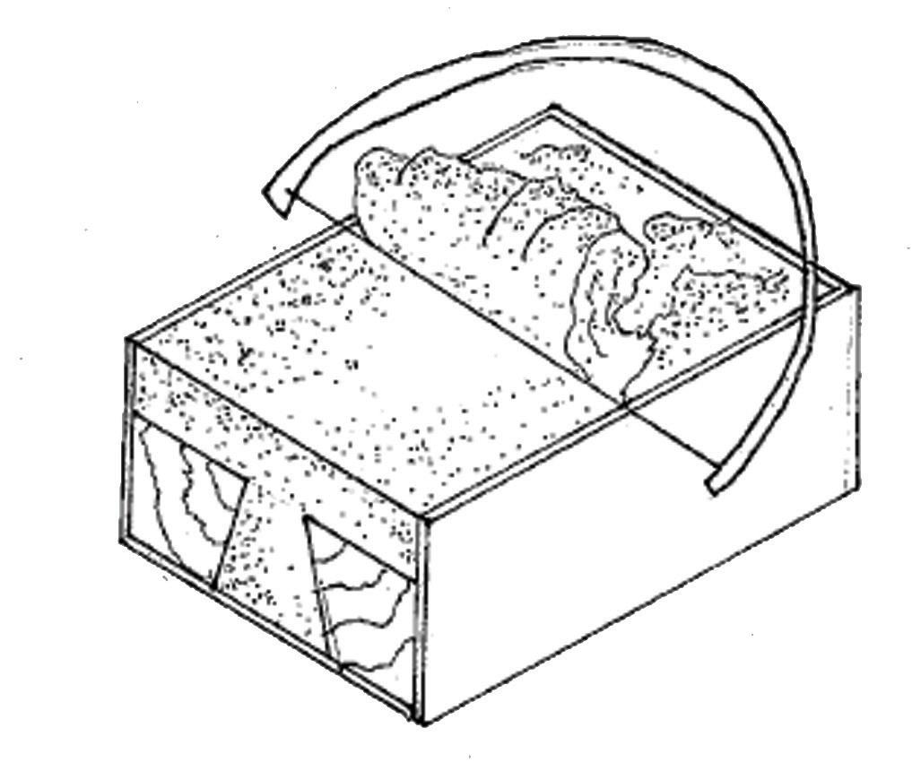
Initially 4 bricks were kept in the formation as shown in the picture which served as a form-work to cast the block. The bricks were kept up to 1 course. Concrete (1:3:3) was poured in the void created in between. The dimensions of the block were governed by the size of the pier. Thus, the block was cast on site using the local bricks, so that variations in the sizes of the brick would not affect the precision required.
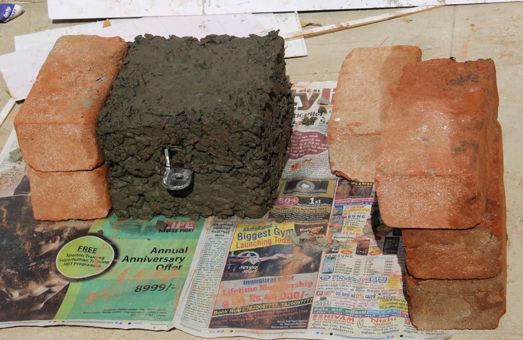
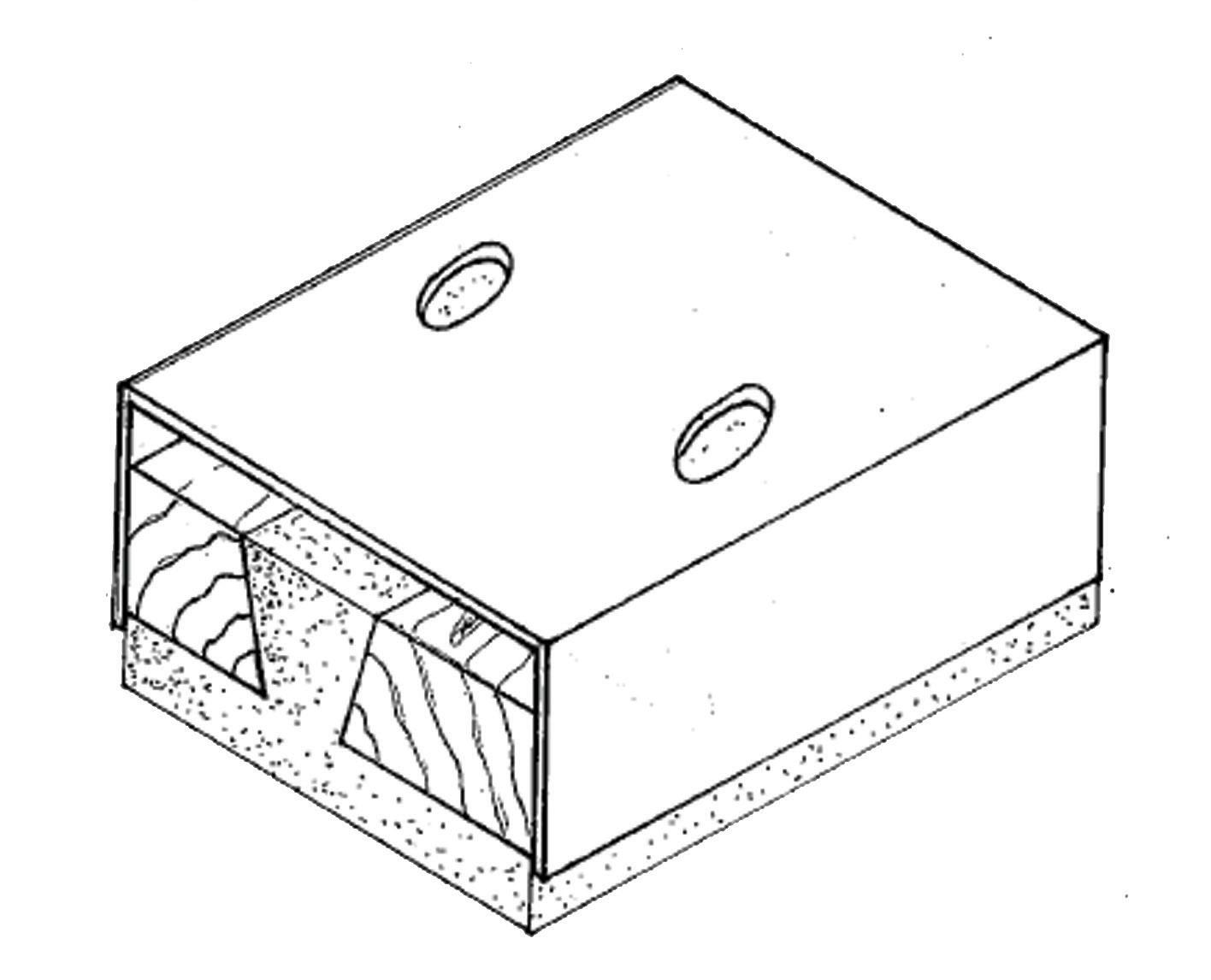
Before the concrete set, a metal clamp, with a hole towards one end, was to be placed such that the hole doesn’t get covered and protrudes out of the block. After placing it, another layer of concrete was to be poured for which the shuttering had to be extended upwards. One course of bricks were placed above the previous ones and concrete was poured in similar manner.
Each pier that had a door to be fixed, required two concrete blocks, one close to the floor and other at the top. One block was kept after 3 courses from the bottom in the brick pier and the second was placed after the 19thcourse in the brick pier.
1

2
3
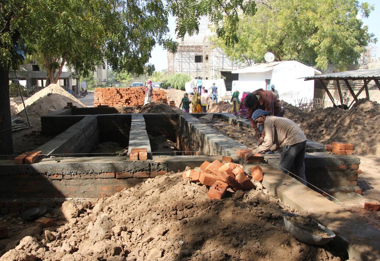
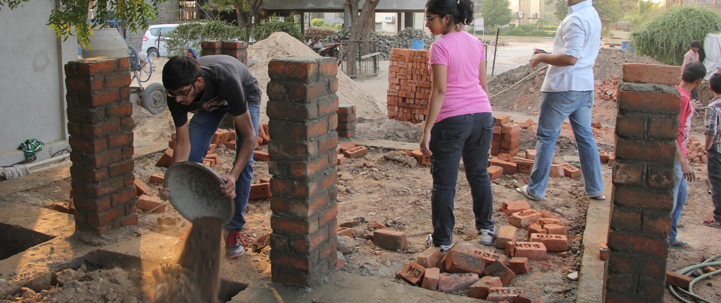
Positioning the first course of brick pier
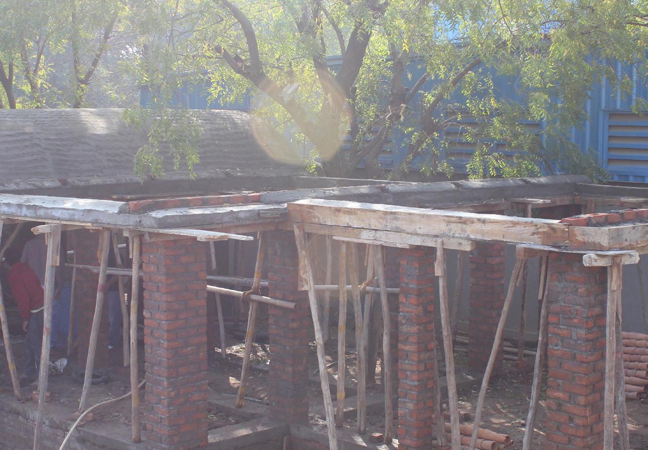
In some brick piers, where the doors were then to be hinged, the concrete blocks were placed. Brick piers were kept up to just 7 courses on the first day in order to let the mortar set and bind the walls well. Therefore the remaining pier was completed on the next day.
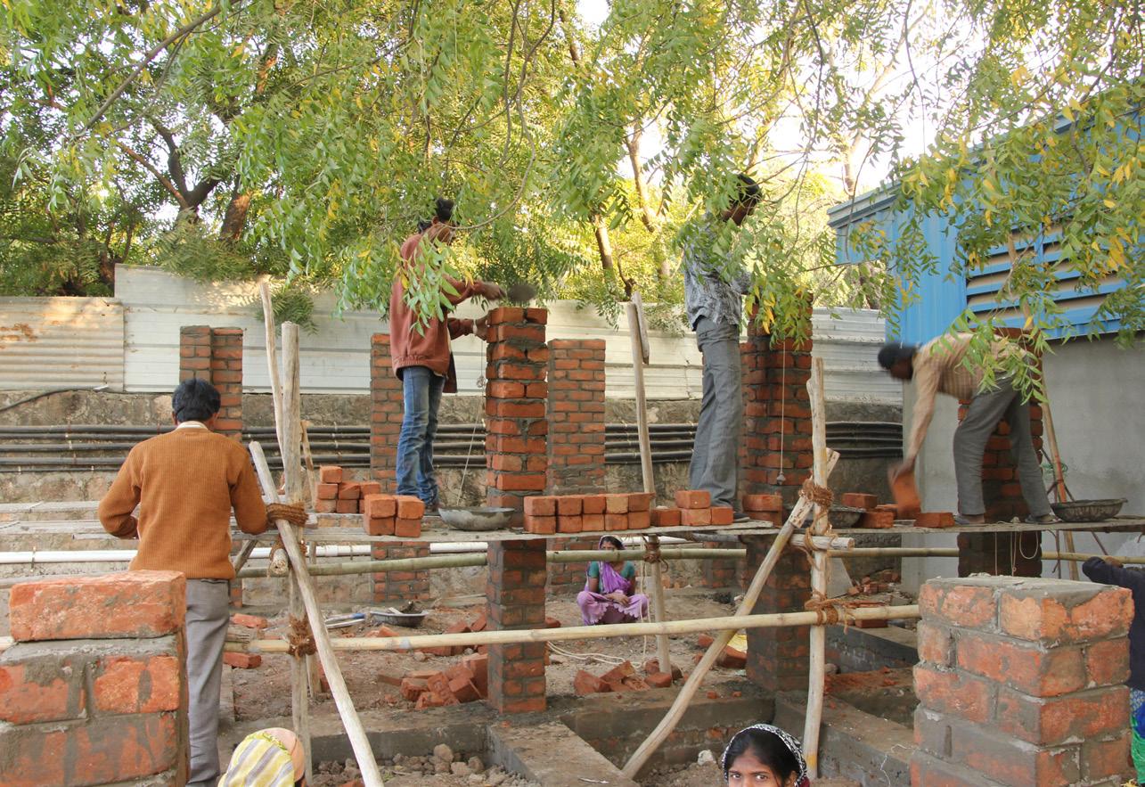
Brick-piers being erected
Once the brick piers were erected, the shuttering for the casting of lintel beam was set-up. The reinforcement for the lintel beam was prepared during construction of brick piers itself. The thickness of lintel beam was kept 200mm.
* Curing time for brick piers is supposed to be more but owing to time constraints we started after one day

Centering at the lintel beam
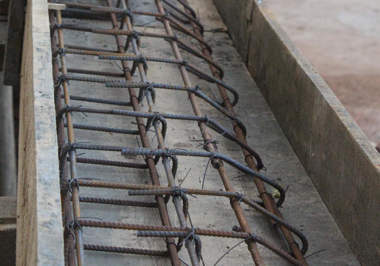
Reinforcement of the lintel beam Once the centering was complete ,the reinforcement was laid in. The steel bars with 12mm diameter were used as a reinforcement. After the completion of shuttering and checking the junctions of reinforcement, concreting of the lintel beam was done.
6.1 Casting of Lintel
The picture here shows the supports given to the shuttering for the lintel beam.
Support given to centering
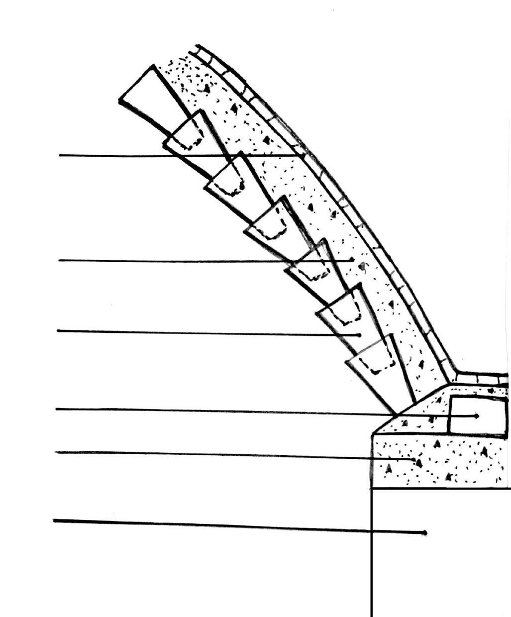
In this structure the roofing system consists of a vault. The vault needs a base point to start from. As a result the Brick Chair is made and the first Guna tile of every course rests on this Brick Chair, which helps in achieving the curve for the vault.

Sketch of reinforcement in lintel beam
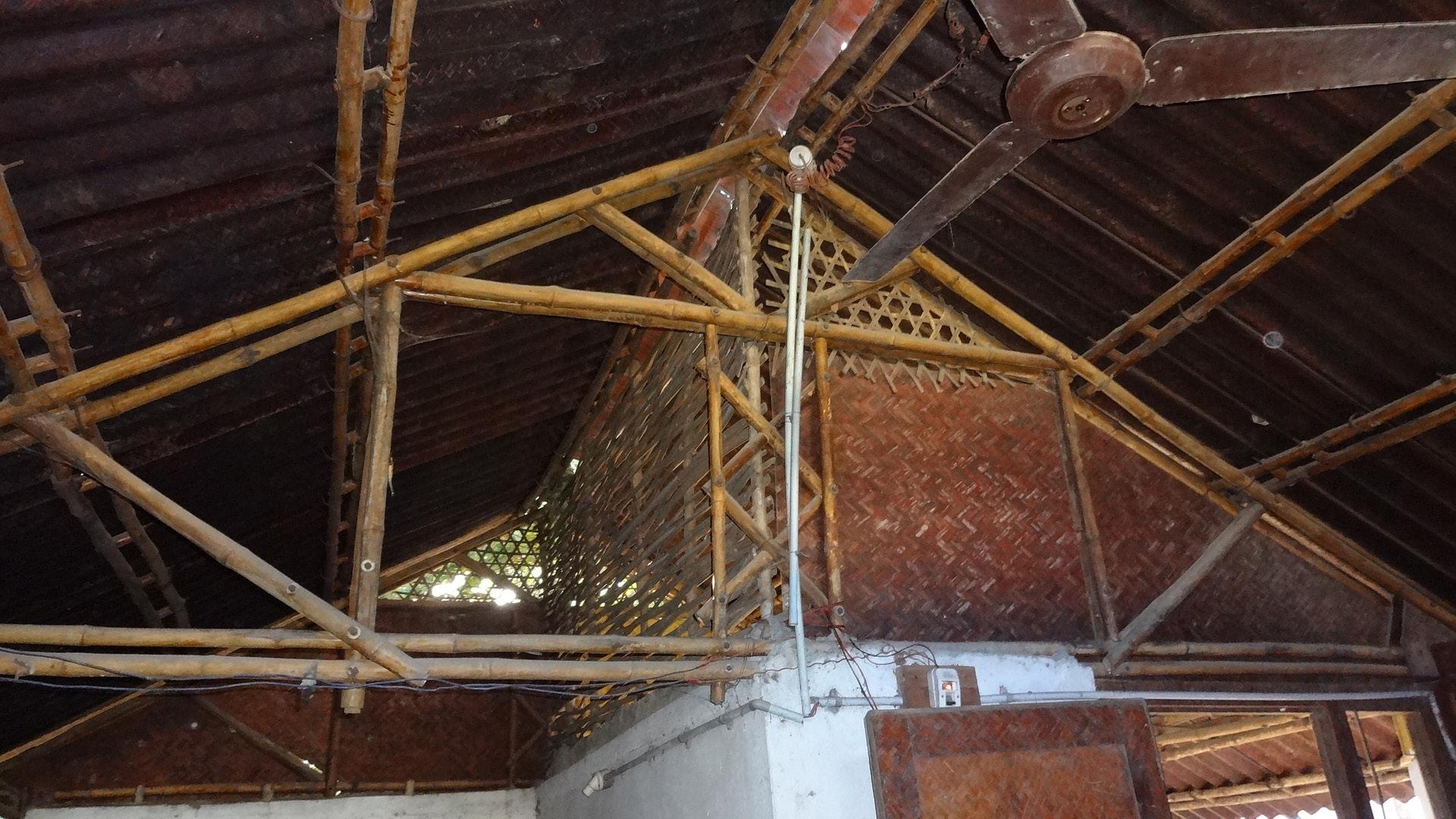
Roof Truss supported by wooden member
The sketches here shows the details of the Brick Chair that is set on to the lintel beam. Brick masonry chair is placed at the springing points for placing Wardha tumbler bow. Concrete mix (1:2:4) is placed at an angle so that the tumbler bow rests properly on the chair.
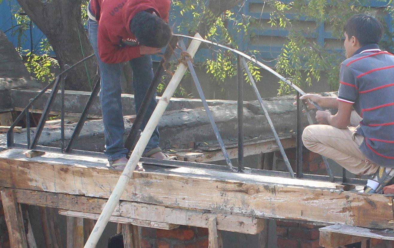
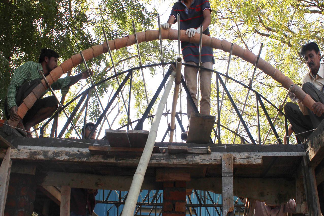
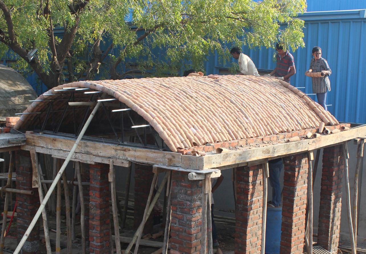
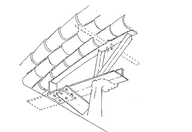
Fixing of roof Truss The steel frame forming an arch here is called the Roof Truss. The purpose of the roof truss is to give a support to Guna Tile courses until the roof can take its self-load and also to help achieve the curve. The further pictures also describe the removal of this Roof Truss and how the roof becomes self-dependent.
The truss is designed in such a way that it can be easily removed once its purpose is fulfilled. The truss is supported by the wooden member shown in the picture. So, once the wooden member is removed the truss can be easily pulled out from its place.
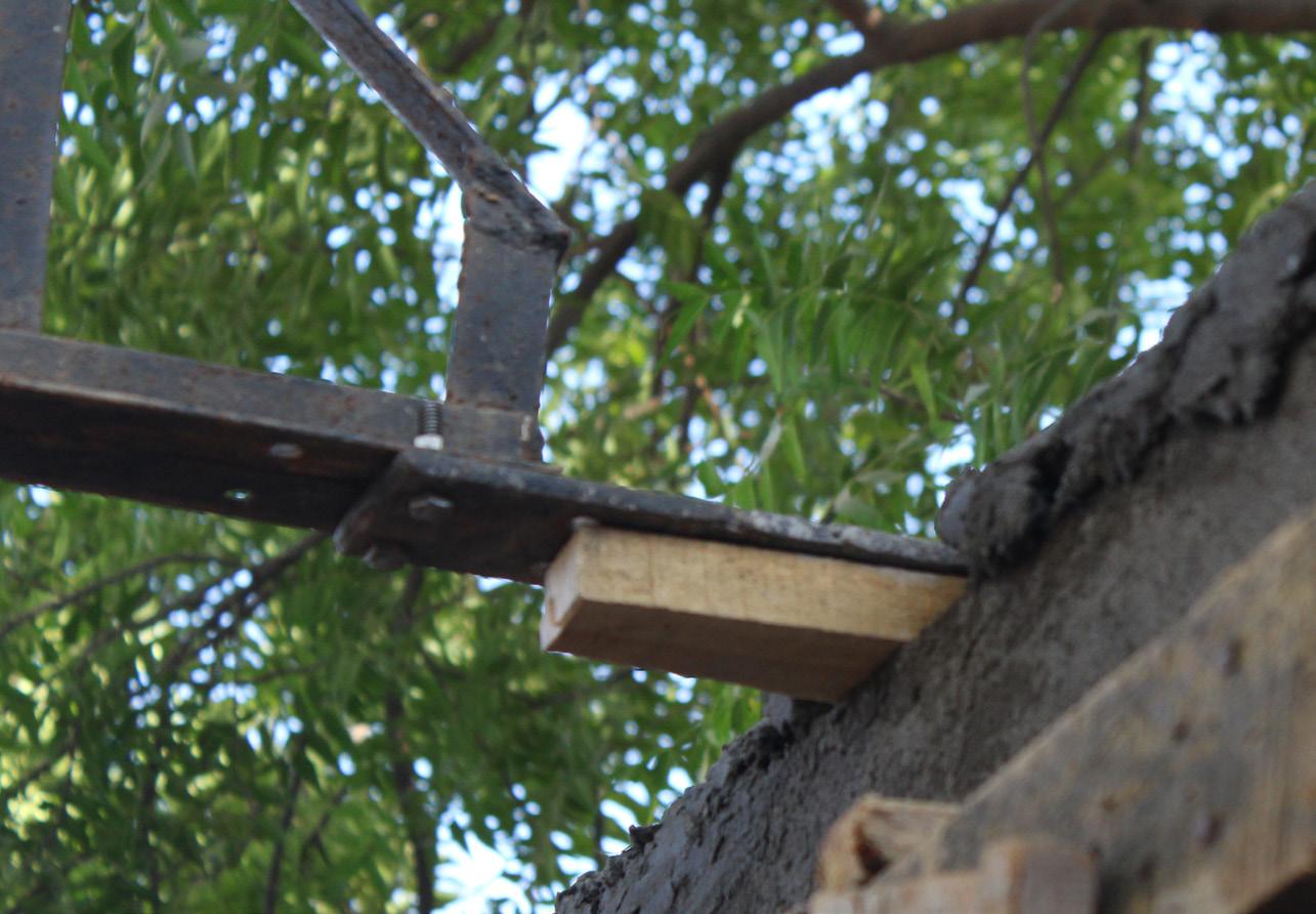
Wooden support given to roof truss
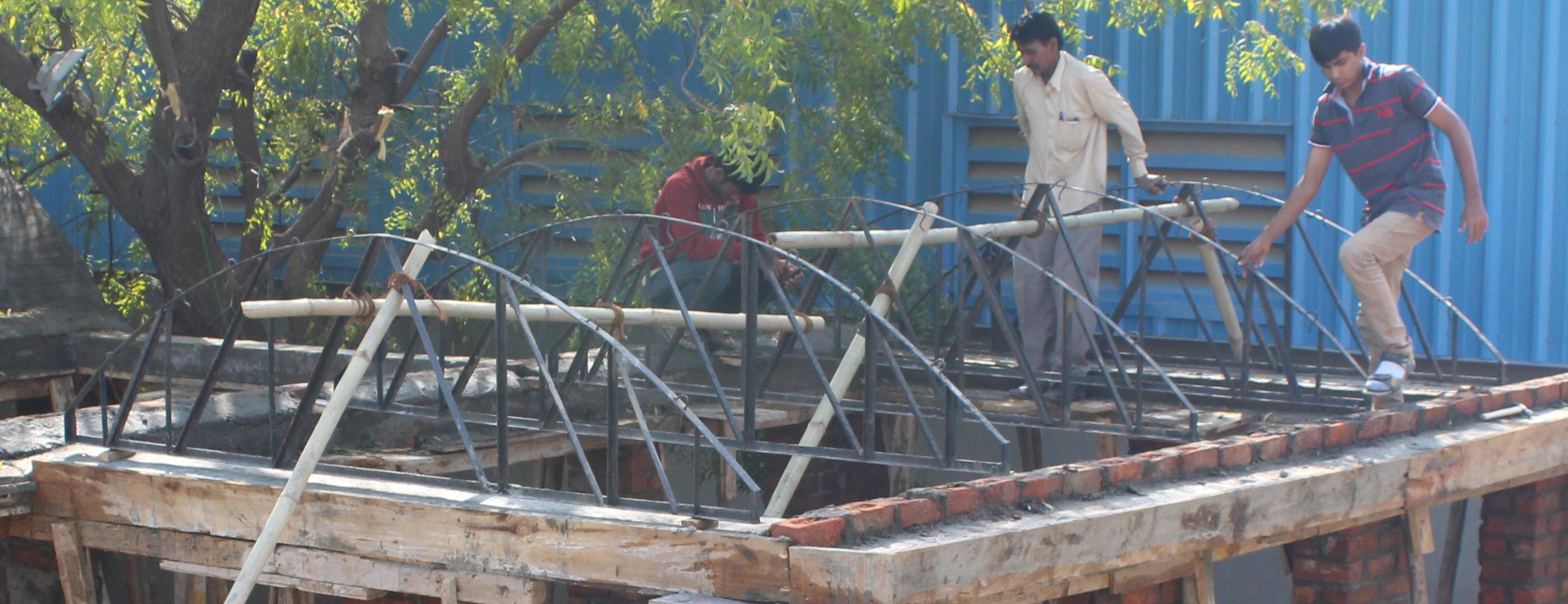
Trusses being placed at regular interval
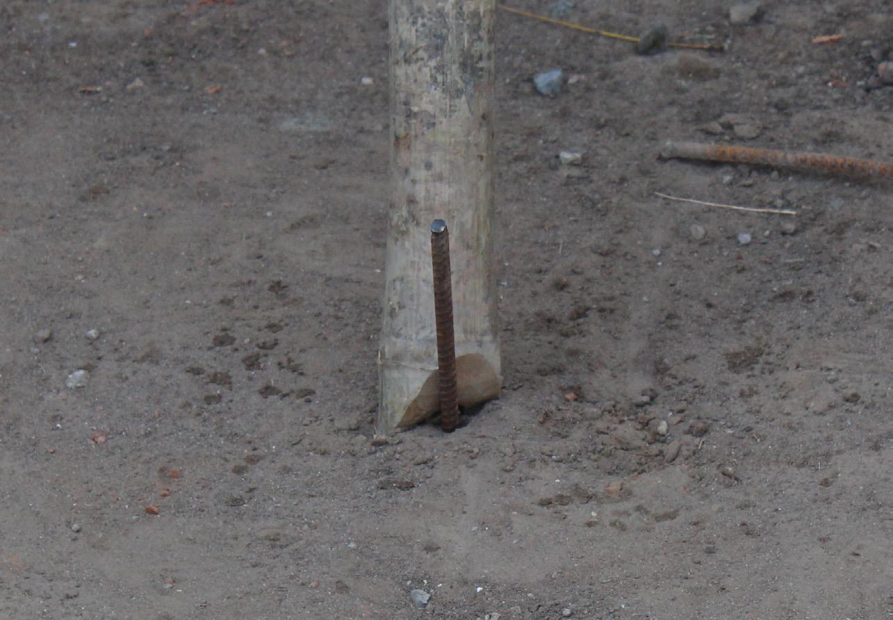
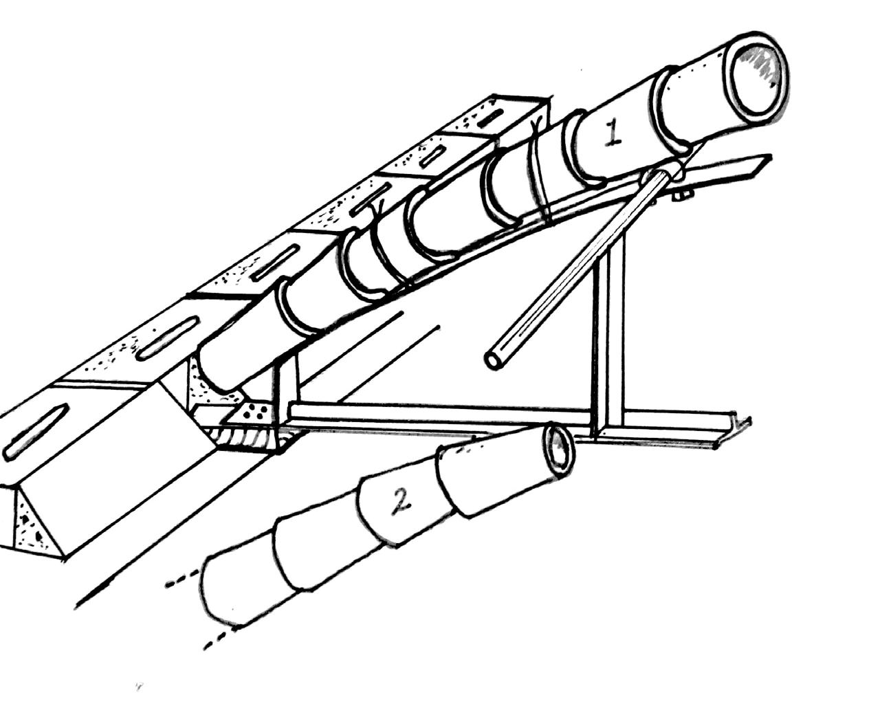
Ground support The first and the last truss of every vault borrows its support from the ground, so that it does not get inclined while laying of the Guna Tiles. The trusses in between are connected to either first or the last truss. These trusses are connected by bamboo.

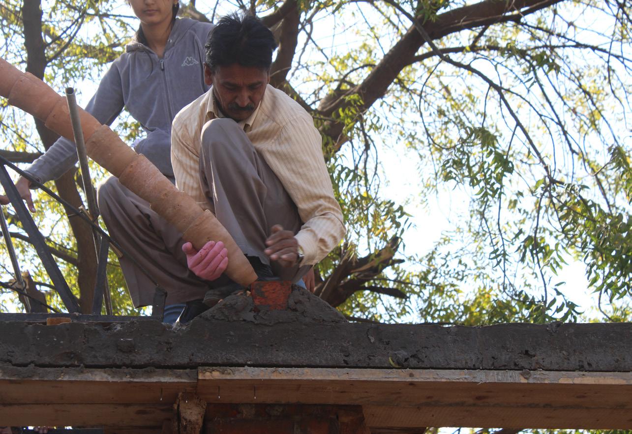
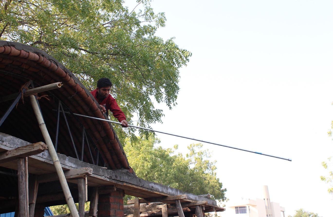
The arch of these trusses have small voids at regular intervals, through which the GI pipes are passed. These GI pipes are connected by the GI couplers. These pipes act as supporting member to the Guna tiles, as the course of Guna tiles cannot take the load of itself.
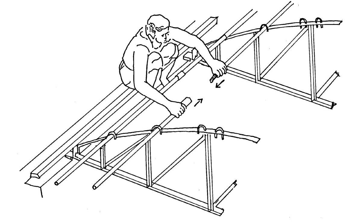
Inserting G.I. pipe into roof truss

Connecting G.I. pipe by G.I. couplers
The voids through which these pipes are passed are wider than the external circumference of the pipe, as a result the pipes remain loose. A small piece of bamboo is used as a spacer, to keep the pipe intact with the arch and ensures its firm position when it has to bear the load of the roof.
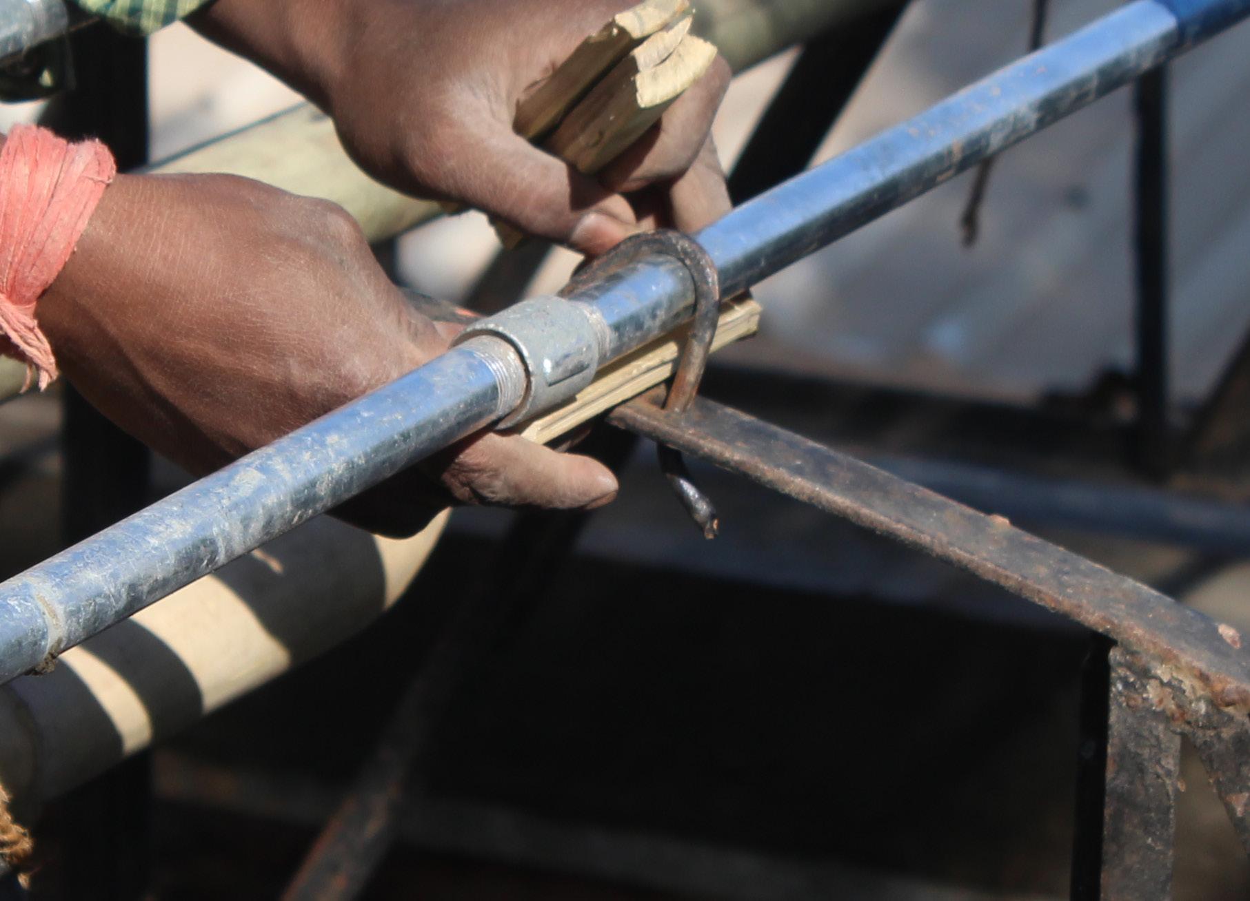
Wooden piece for fixing the G.I. pipe
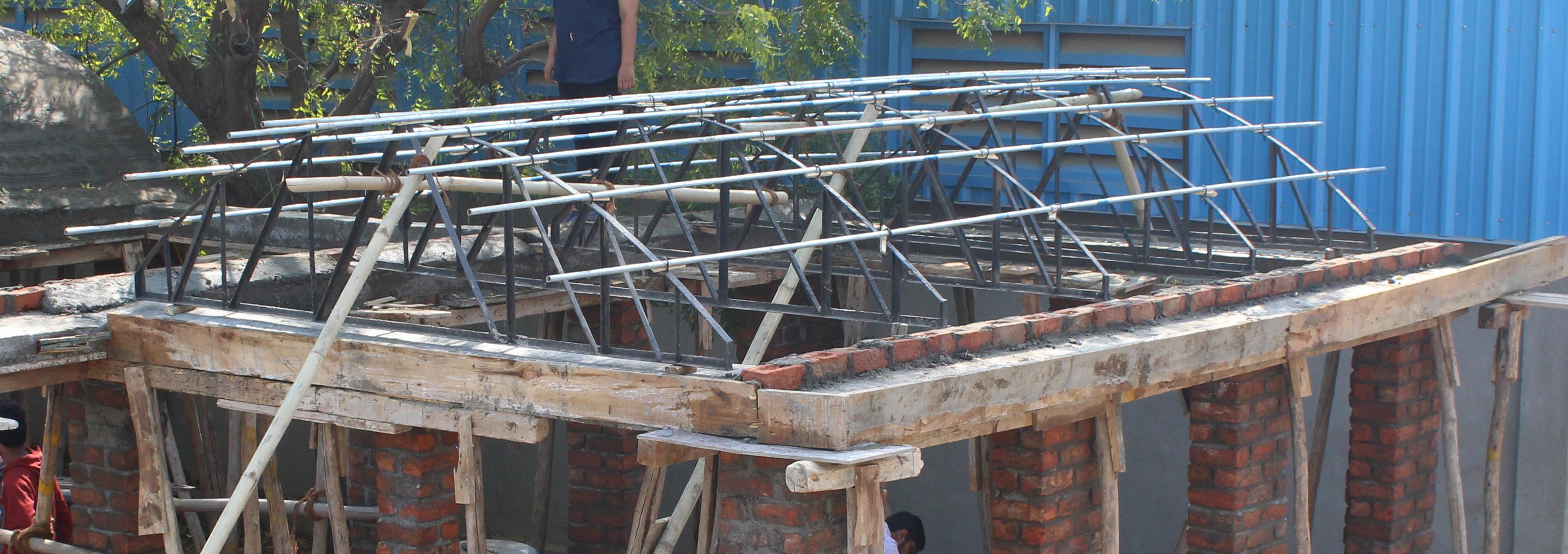
Roof truss supported by Bamboo and connected by G.I. pipes
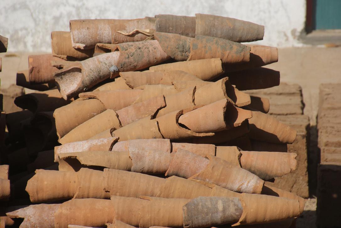
Making of cylindrical lumps
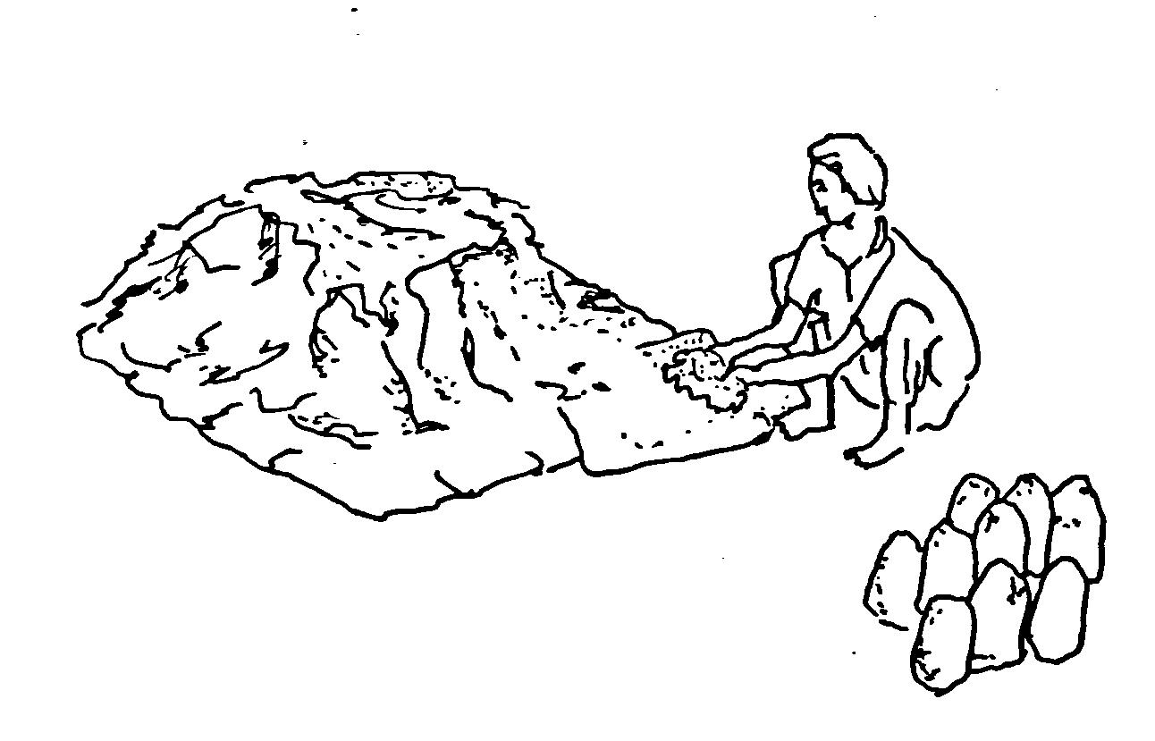
Making cylindrical lumps hollow from one side These Guna Tiles are manufactured by the potters using the locally excavated mud. Potter then makes small cylindrical lumps after out of the potter clay.
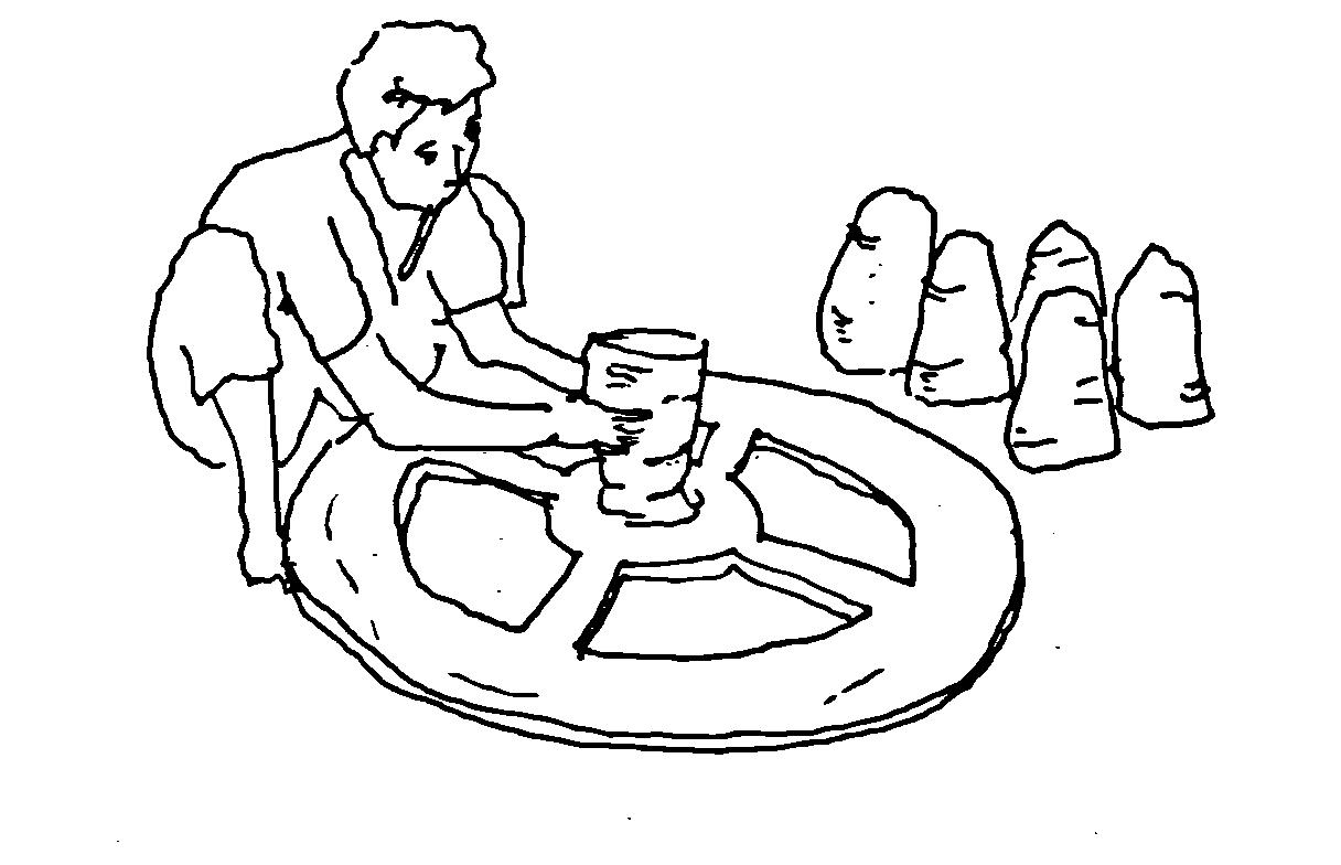
These cylindrical lumps are then given shape and made hollow from one side, which leaves them closed from the other side. But still these are very wet to be further worked on. Therefore these objects are kept for drying for some time.
After gaining some basic strength, these objects are again kept on the wheel and are made hollow from the other side. This final product obtained is called a Wardha tumbler(Guna Tile).
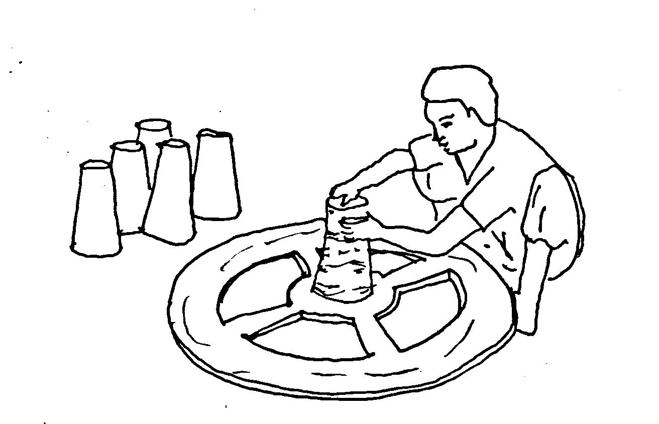
Making cylindrical lumps hollow from second side
Dimensions of a Guna Tile.
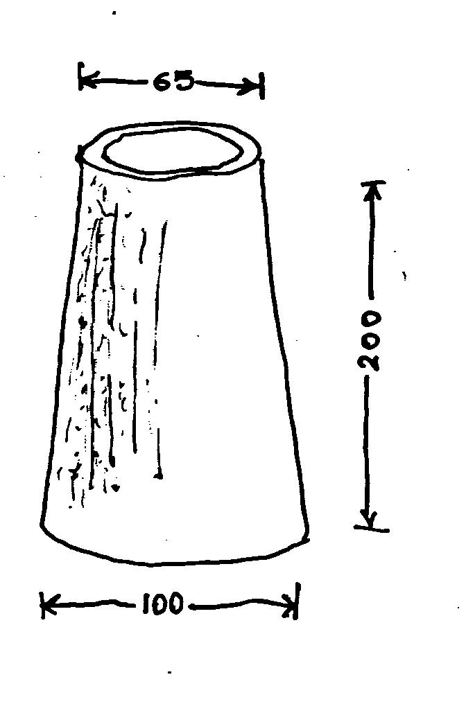
Dimensions of Guna Tile
9.1 Laying of Guna Tile
Laying of first bow (at Guna Tile) The picture here shows the laying of first bow of Guna Tiles for the roof. It also shows the truss and GI pipes being used as a to support the Guna Tiles.
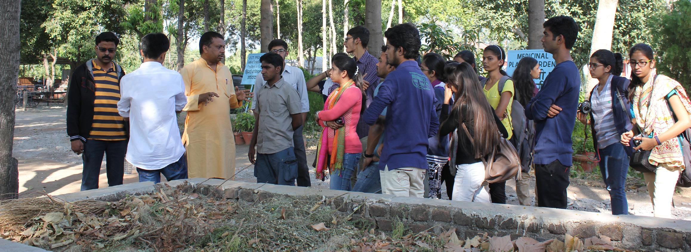
The picture shows artisan showing students laying of last guna tile on brick chair.
Guna Tile course resting on Brick Chair
After the first course of Guna Tiles is laid, GI pipes and the Guna Tiles are tied with a thin wire so that the course does not move from its place, as remaining courses of Guna Tiles are laid considering the first course as a reference.
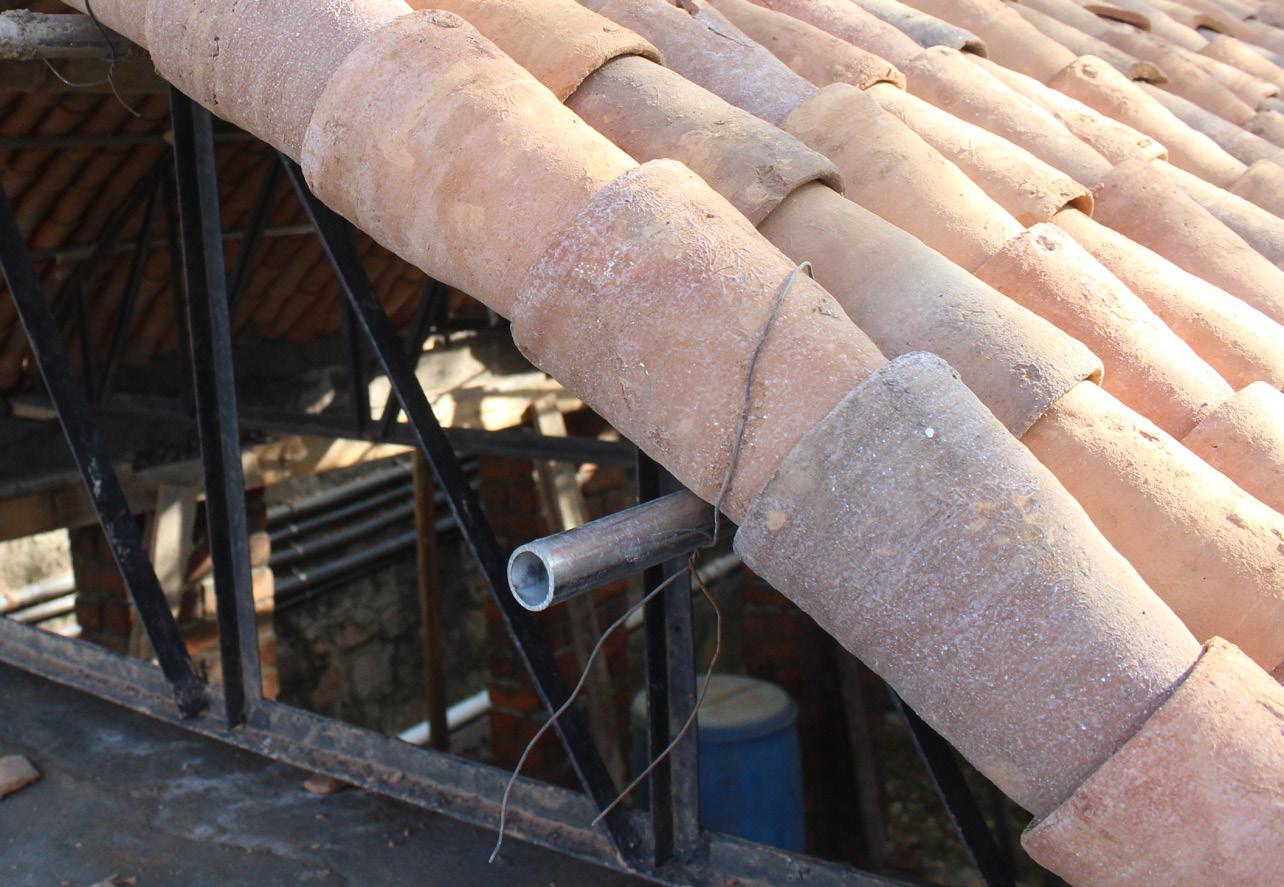
First course tied to G.I. pipe
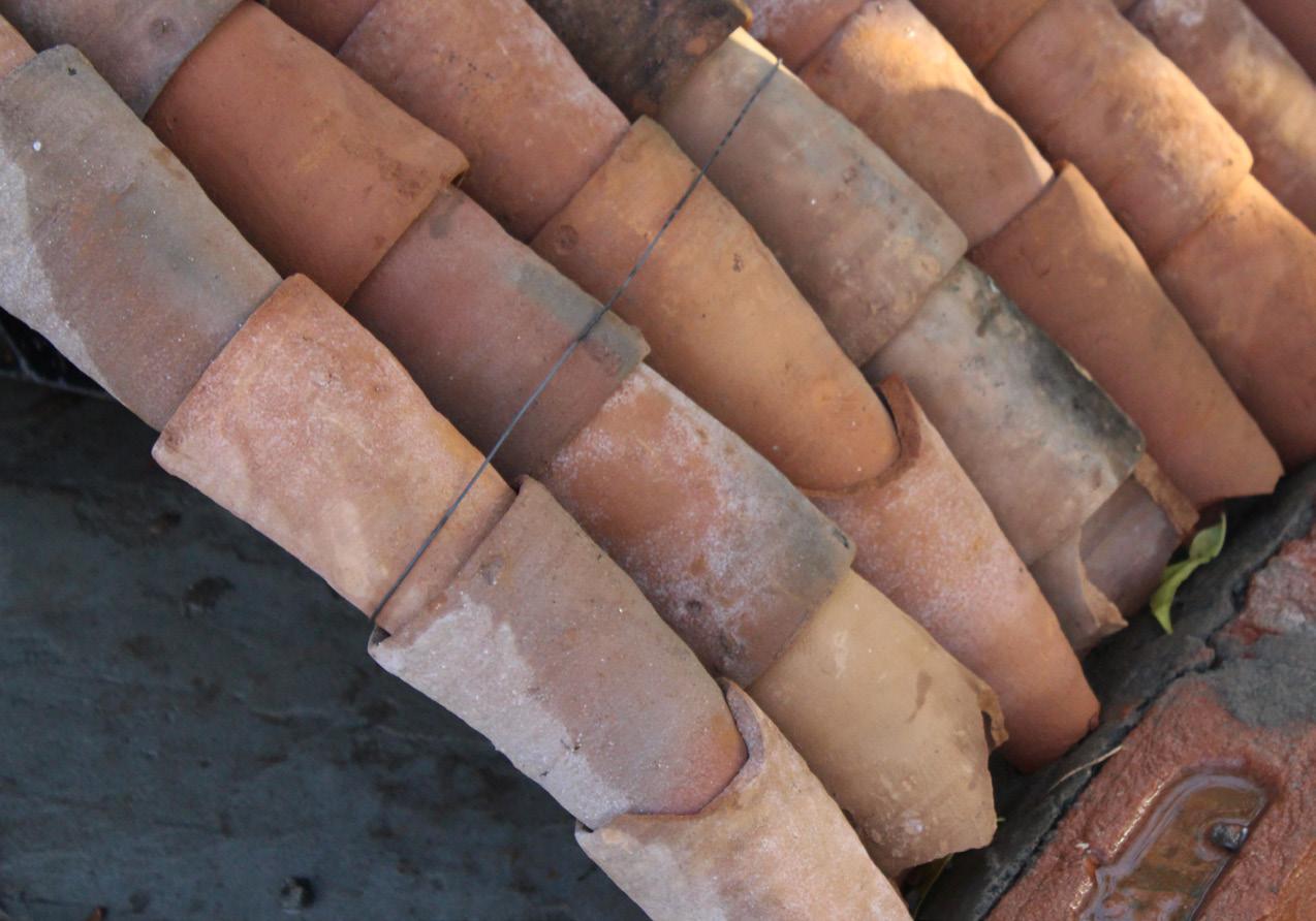
First four courses tied to G.I. pipe Once the first 4 Guna Tiles courses are laid, they are tied to each other using the same thin wire.
After every Guna Tile course, the course adjacent to it is kept in the opposite direction so that the void space being created can be reduced.
Each course is arranged in opposite direction
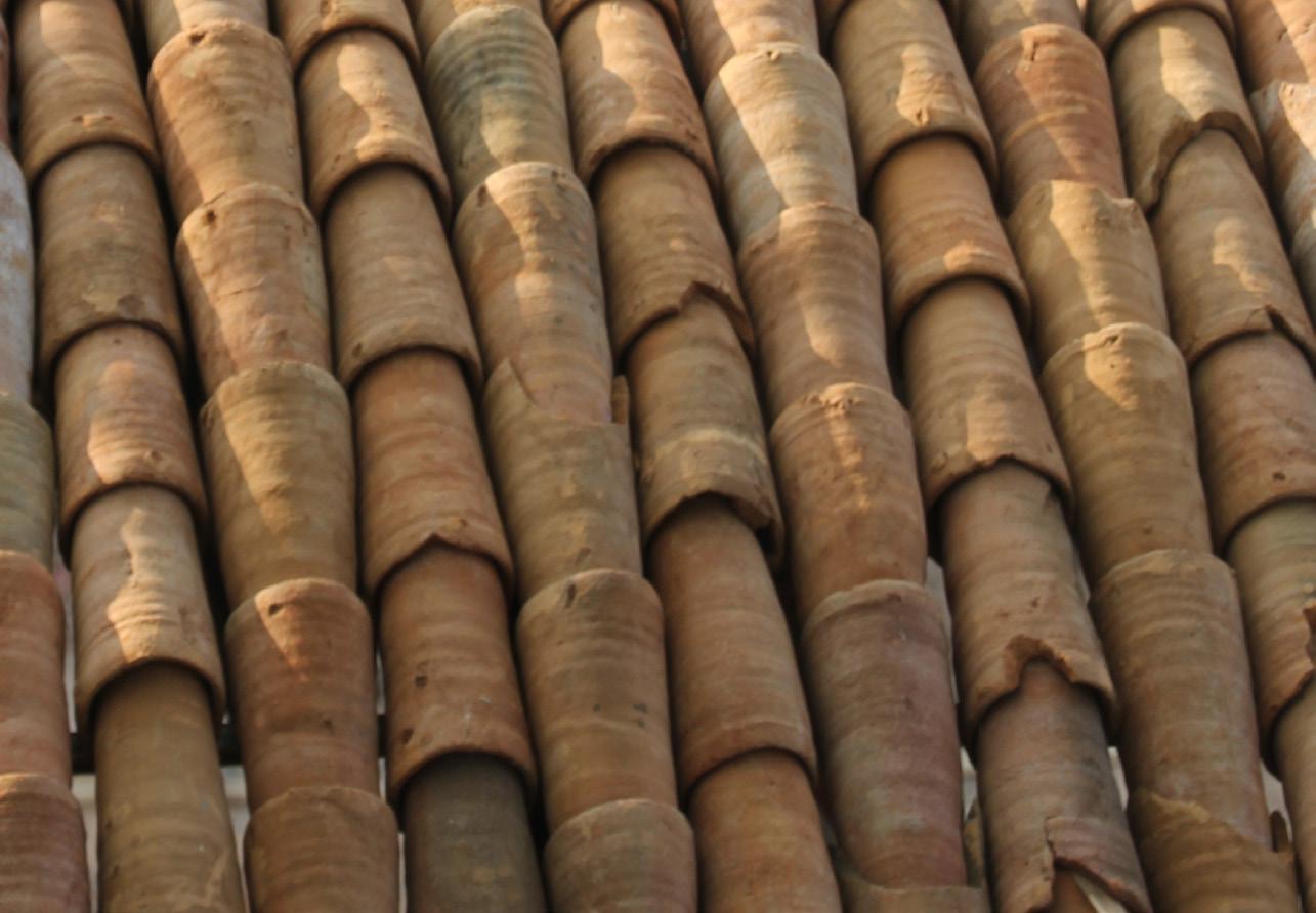
Laying of Guna Tiles Each of the Vault consists of 50-55 courses of Guna tiles, this number depends on the length of the vault to be achieved.

Watering on Guna Tiles (vault) Once the whole vault is complete, water is sprayed throughout the vault. This is done to prevent the water content in the mortar to be absorbed by the Guna Tiles.
After the vault becomes wet enough, cement mortar is applied to the vault. The ratio of the mortar is 1(cement):2(sand)
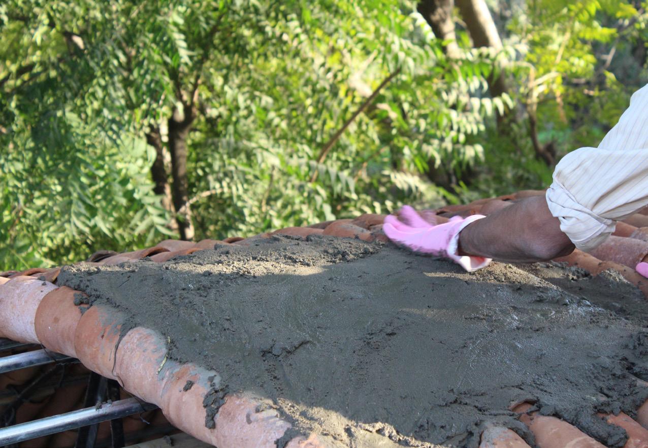
Applying cement mortar on Guna Tiles
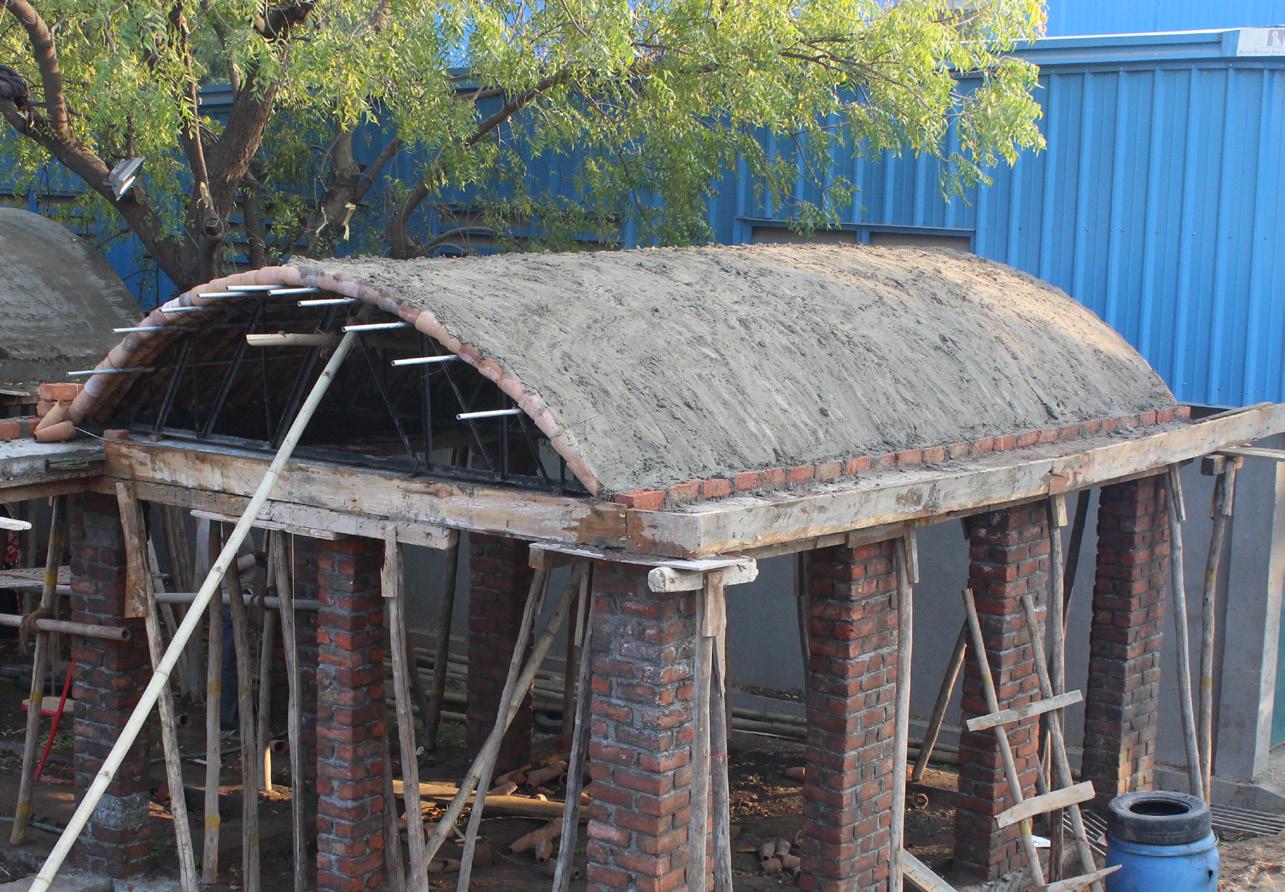
Completetion of first layer of mortar bed Once the 12 MM thick mortar bed is applied above the layer of Guna Tiles, it kept for curing for a single day. Because the Guna Tiles are laid in opposite direction, the mortar does not fall down.
After the first layer of mortar second layer is applied after 24hours.
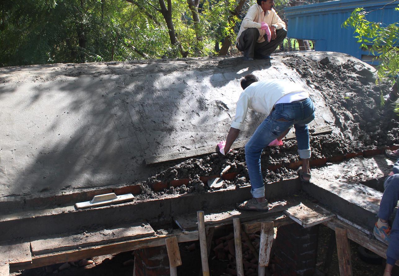
Giving finishing touch to mortar bed
10.1 Laying Of China Mosaic
After the second layer of mortar china mosaic tiles are laid on top surface of vault to make this structure water proof.
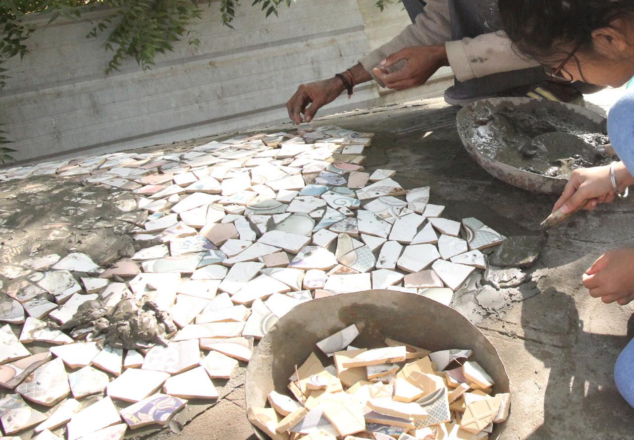
Laying of China mosaic
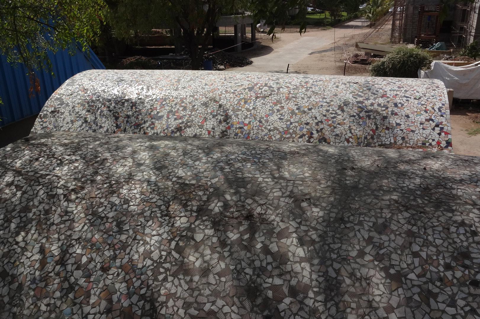
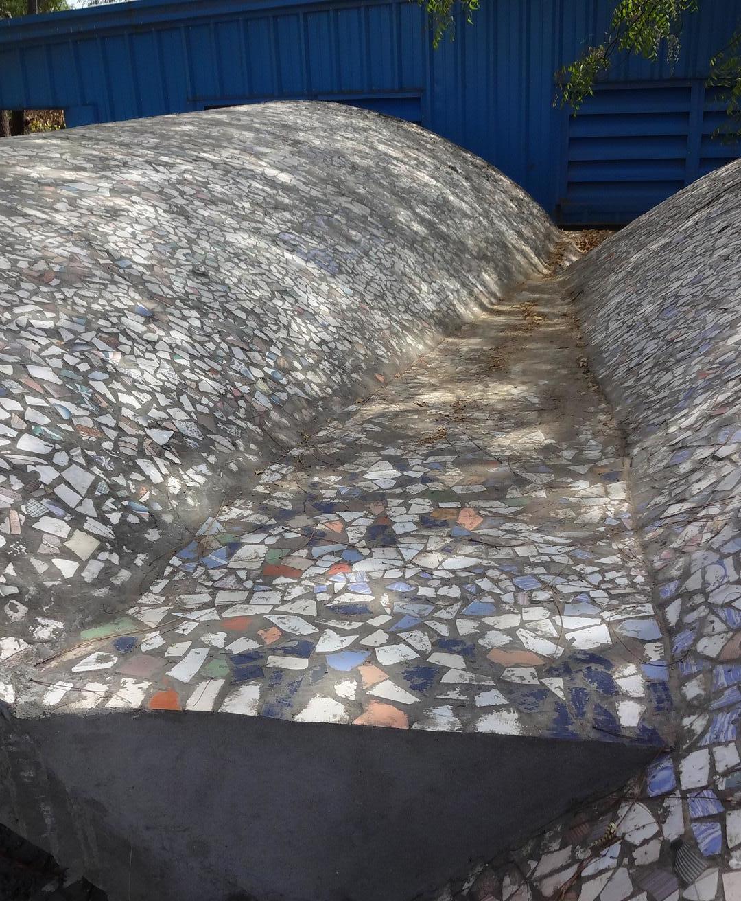
Completed China mosaic Completion of China Mosaic of vaults.
10.2 Section Of Roof
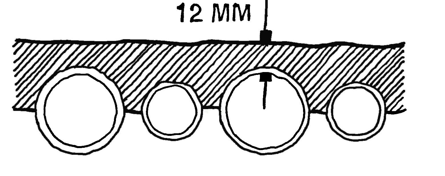
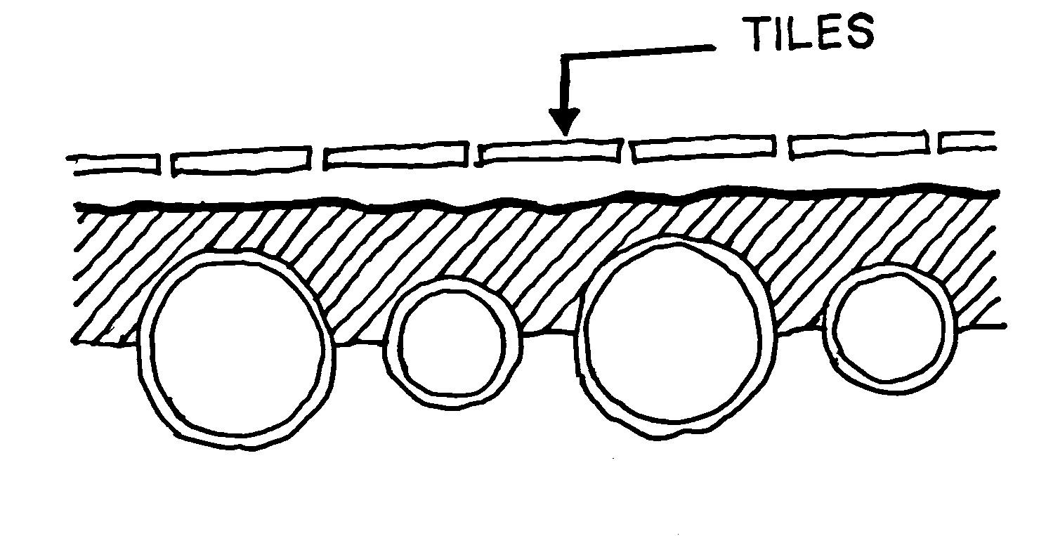
Section without China mosaic Section after applying China mosaic
china mosaic layer
50mm thick cement motar layer
Guan Tile
Masonery chair 200mm thick lintel
brick peirs
Section from one end of the vault
Gutter between two vault The gutter helps in draining out all the rain water being collected between the 2 vaults. This slope is then connected to the pipe which drains the water out of the structure.

Drainage pipe
Removing the wooden member supporting the truss
After the construction of roof is complete, it is capable to take its own load without any support. Therefore, the trusses and the G.I pipes are removed from their place and fixed in another place so that they can be used to make another vault.

Seperating the G.I. pipes (opening G.I. couplers)
Firstly, the GI couplers are released from the GI pipes and then, these pipes are taken out of the truss. After that the support to the trusses are removed, these trusses are taken down from their respective positions. It takes three days in the construction of one complete vault, which involves the fixing all the temporary supports like truss, pipes, laying Guna tiles, applying china mosaic and then the removal of all the temporary supports.
Removing the G.I. pipes
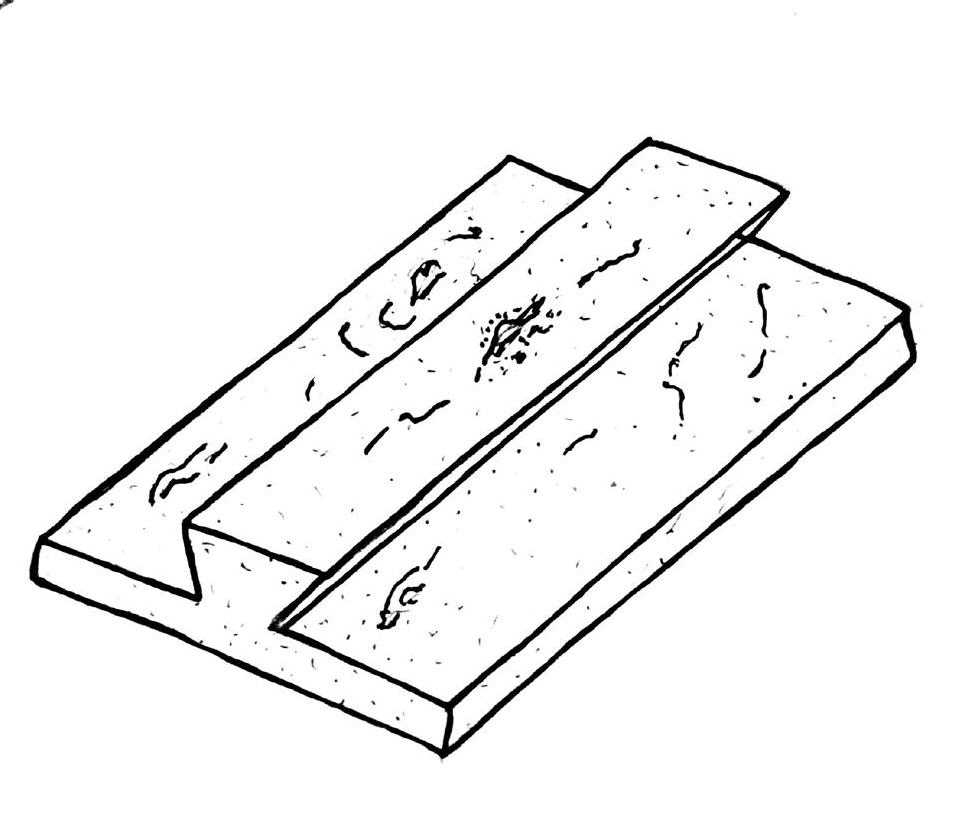
Dimention of wooden piece Initially two wooden pieces are shaped according to the dimensions shown in the sketch. Then these two pieces are arranged in the mould. A fine powder of burnt bricks(made by crushing the bricks) is sprinkled on in this mould.

Once the powder is sprinkled, the remaining space of the mould is then stuffed with the potter’s clay (same clay used for making of Guna Tile). The powder is sprinkled so that the wood does not absorb the moisture from clay and does not stick to it. Also this will stop the wood from expanding and the dimensions of the all the face tiles made from each mould will be same.
Dimension of mould for Face Tile
The clay is tightly stuffed inside the mold so that there are no air pockets in the Face Tile, once it dries. Then the remaining clay coming out of the mold is removed by a straight thin wire to give it a even surface.
Removing the extra clay
The mould is then inverted upside down. Then with the help of two fingers the wooden pieces are pushed out of the mould. Then the same mould is used to make other Face Tiles.
Emptying the mould
Once a Face Tile is removed from the mould, it is then kept in a kiln for firing it. This way the Face Tile becomes baked and is then further used as a component in the making of Mud Bricks.
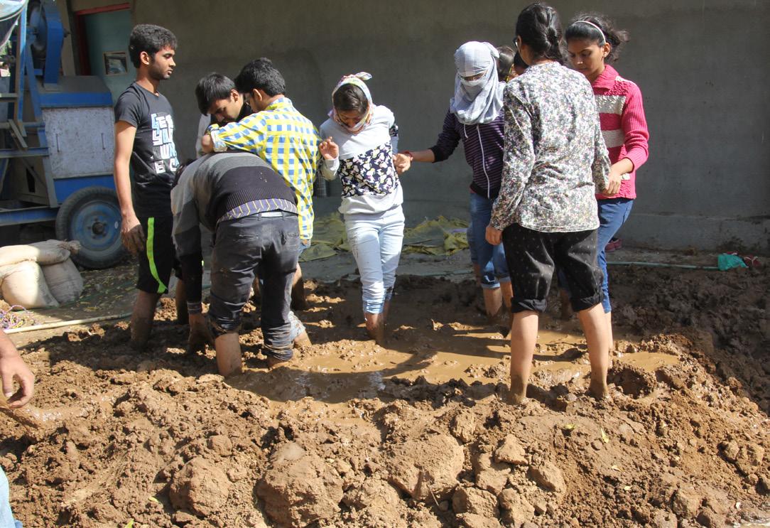
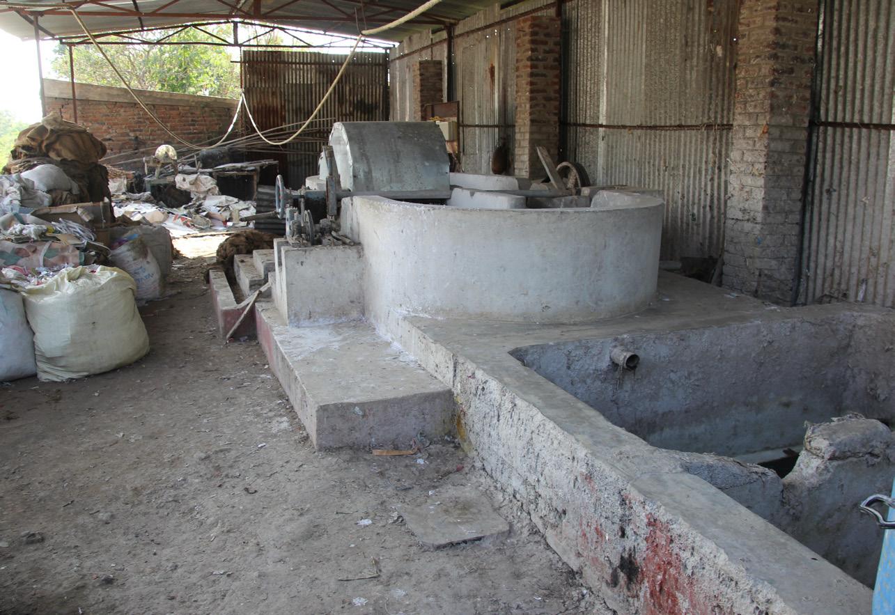
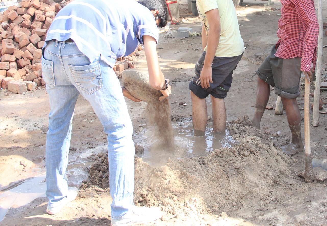
Pugging
1
The process that goes into the making of Mud Bricks has majority of similarities to the that of Face Tiles. Soil is kept in ample amount in which a pit is made where water is poured. Later hay(dry grass) is added which acts as a binding agent in Mud Bricks and prevents cracking. All these elements are then pugged until a fine and very thick paste of the mixture is achieved.
There are 6 main steps involve in the making of Mud Brick, which are as follows:

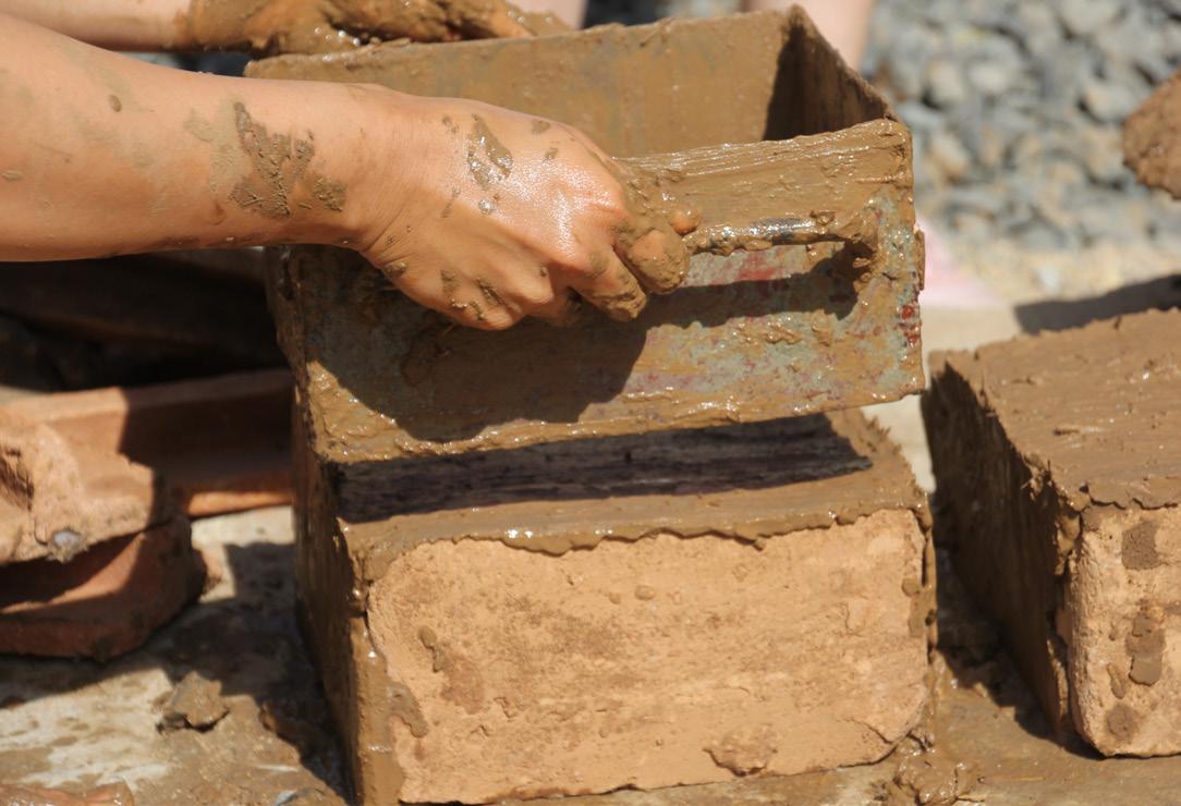
At first the mould is washed and is kept wet so that, at the time of removing it, the brick does not get deformed. Then a Face Tile is placed on one of the faces of the mould, as shown in the picture.

3

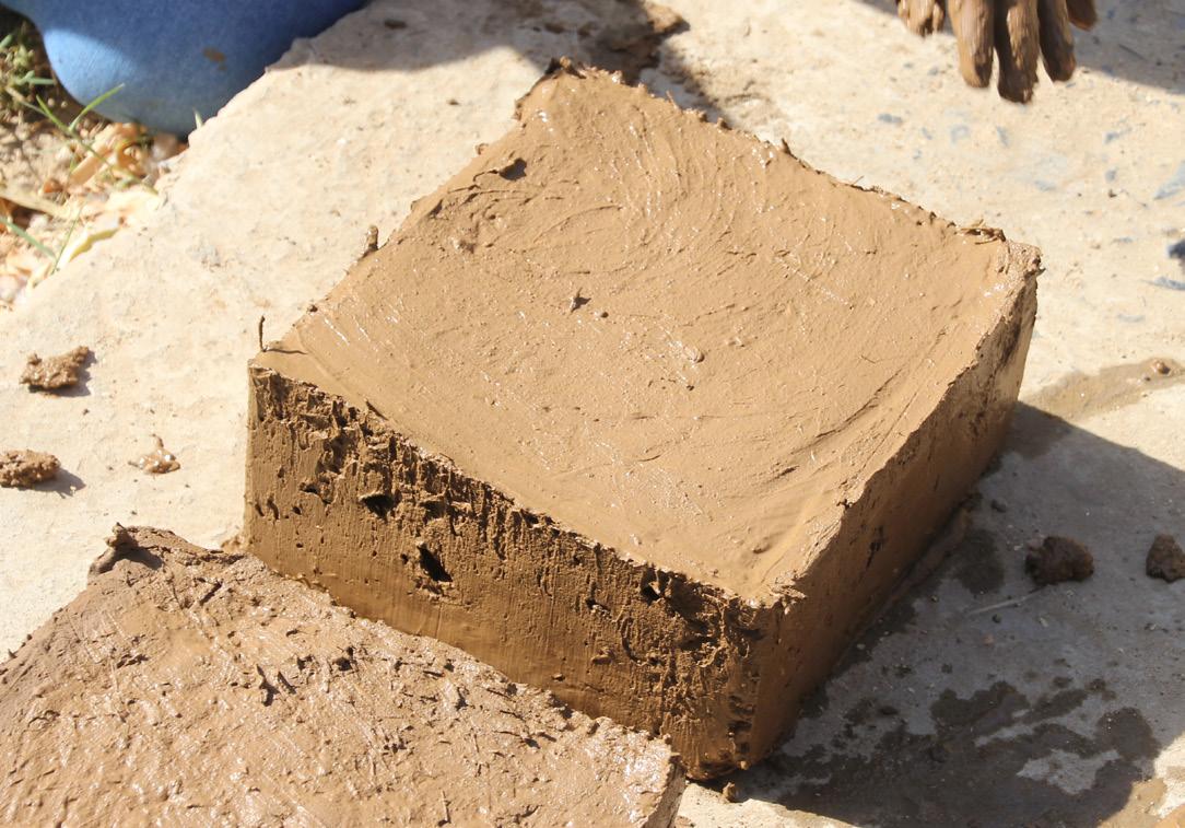
The mould is then stuffed with the paste prepared earlier, till there is no air gap and the wet paste firmly holds the Face Tile from its extruded surface.

5
Then the mould is very carefully removed from the Mud Brick leaving one of the surface of the Face Tile exposed.
The exposed part of the face tile is going to face all the natural forces such as wind, rain water, etc. The Mud Brick is left in open so that the brick dries itself under the sunlight. It takes approximately three days in drying of a Mud Brick.
14.1 Drying Of Mud Block
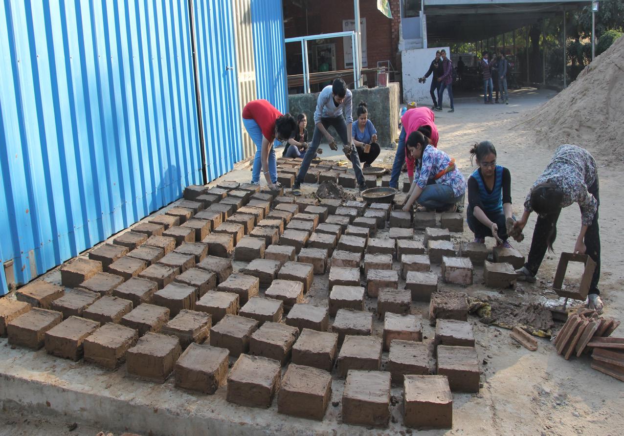
Mud blocks being placed for drying Approximately, 250 Mud Bricks can be prepared by a single person and kept for drying in one day.
The Mud Bricks were then kept for drying for next 2 days, after which they were further used in the making of wall of the Wardha House.

Dried Mud Blocks
The Mud Bricks are bonded to each other by Mud Mortar which is prepared by the composition of soil, cement and water. Firstly, the soil is sieved with a dense wire mesh, so that no rocks or other unwanted elements go in the making of Mud Mortar.
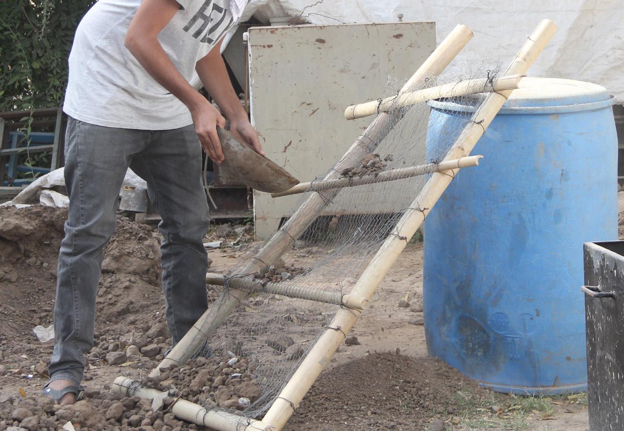
Sieving the soil for Mud-Mortar
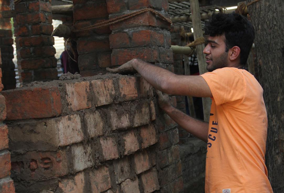
Mixing of Mud Mortar The Mud Mortar is done, which is then used as component of wall.
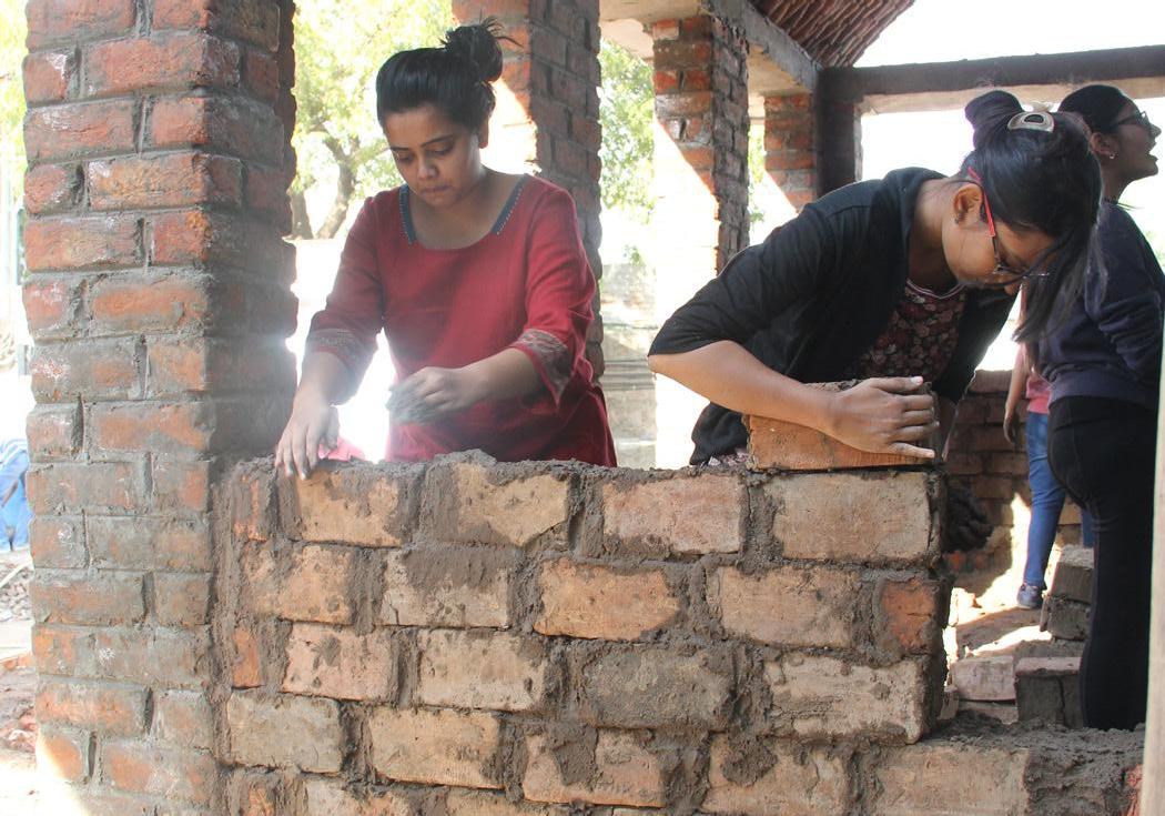
Building and alignment of Mud Bricks with the plinth and wall Building and alignment of Mud Bricks with the plinth and wall
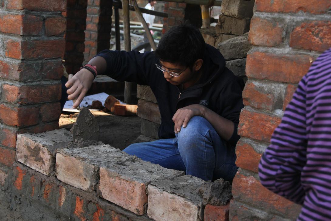
The first course above the plinth level is done using the normal brick, then the remaining courses are made out of Mud Bricks using the Mud Mortar.
Single brick used to complete the Mud Brick course
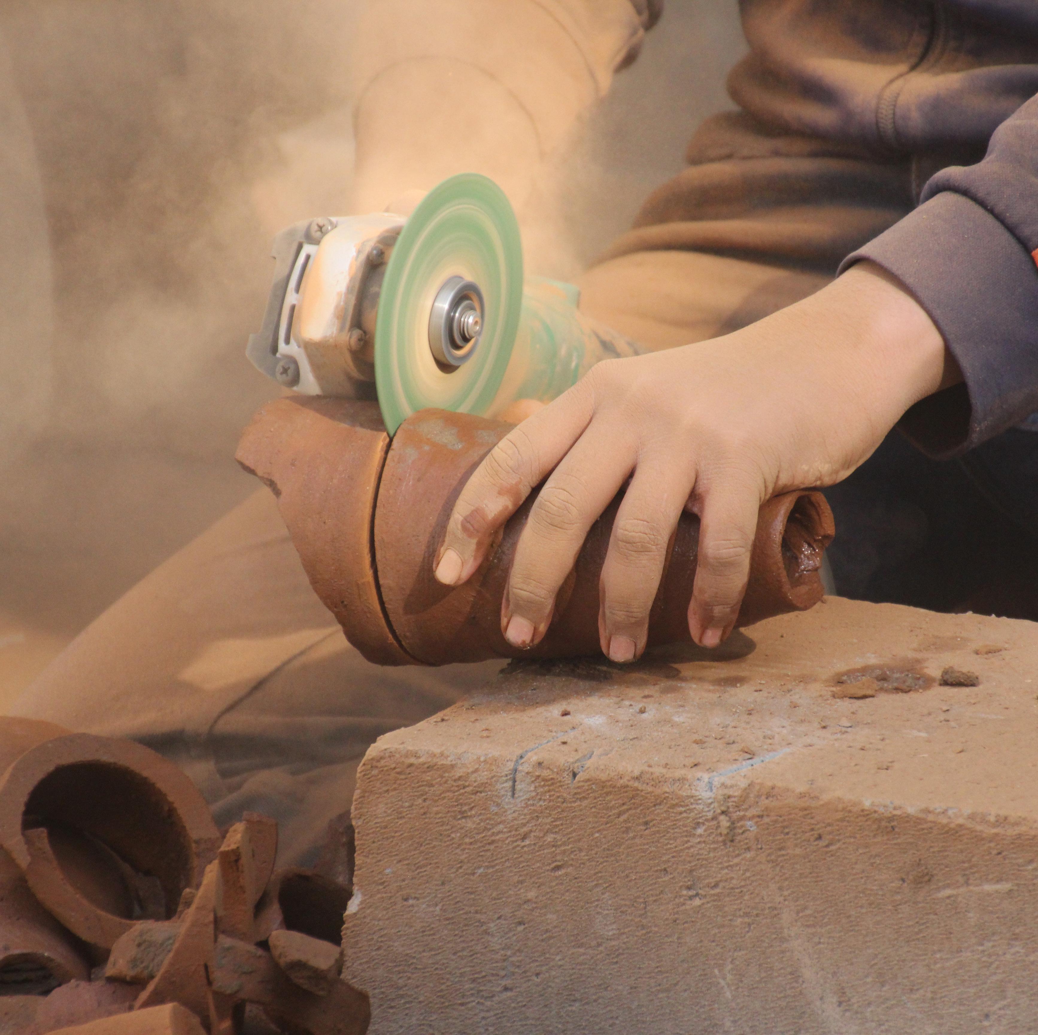
Broken Gun-a tiles being cut Broken Guna tiles being cut
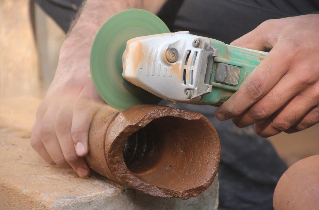
The Guna Tiles which were broken during transportation, were used to make openings. The broken part of Guna Tiles were cut using a grinder, and the remaining part of the tile was used to make the opening. These Guna Tiles were then staked upon each other and bonded using mud mortar. The direction of each Guna Tile was opposite to its adjacent Guna Tile.

Making of Guna Jali out of cut Guna Tiles Making of Guna Jali out of cut Guna Tiles

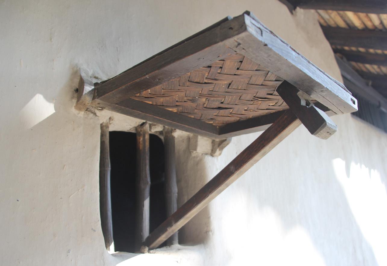
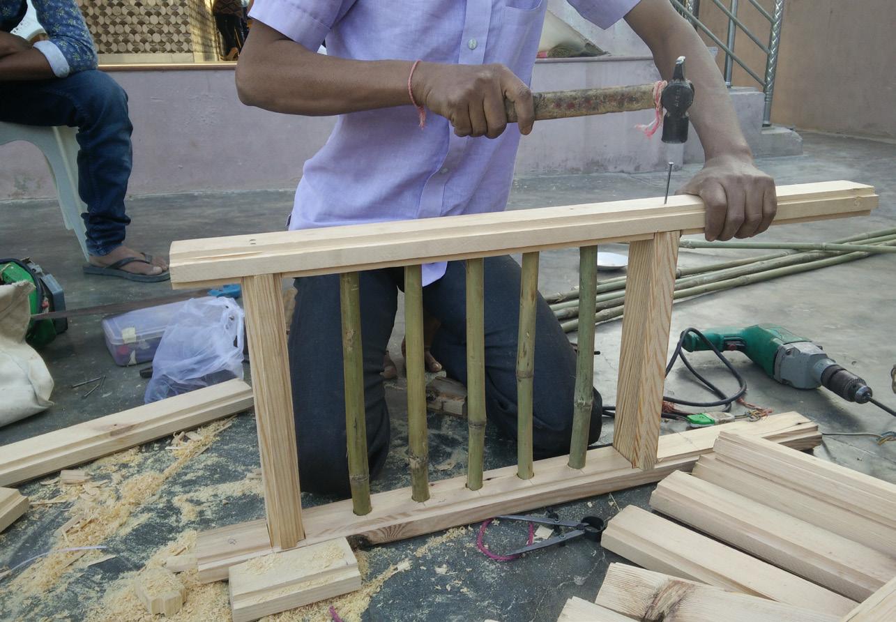
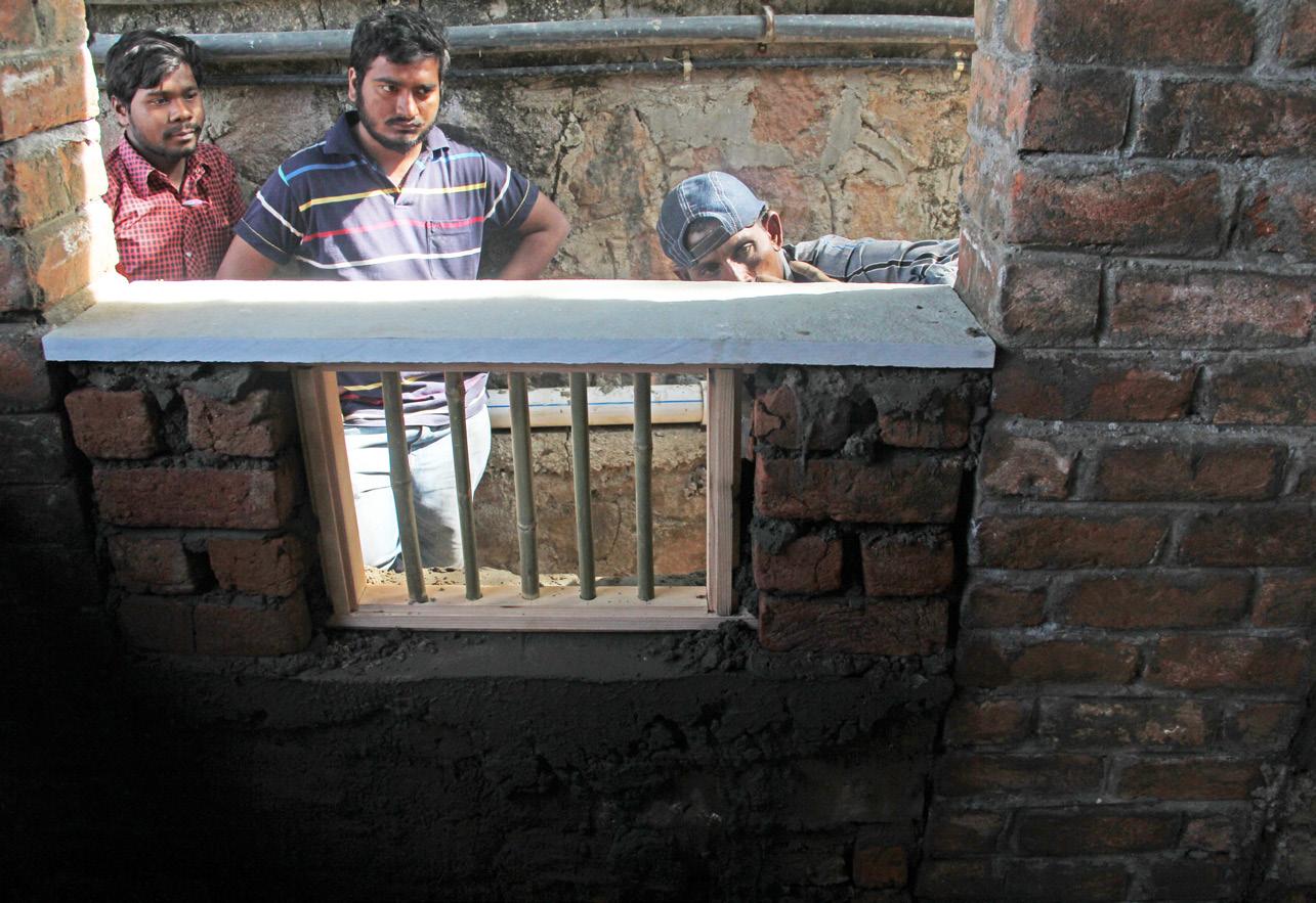
The design of the wooden window includes four wooden member coming together to form a frame and thin bamboo sticks were used to enclose the window.
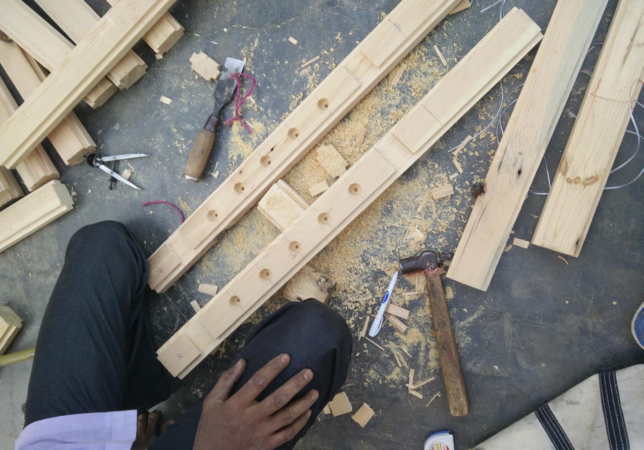
Making of two horizintal logs
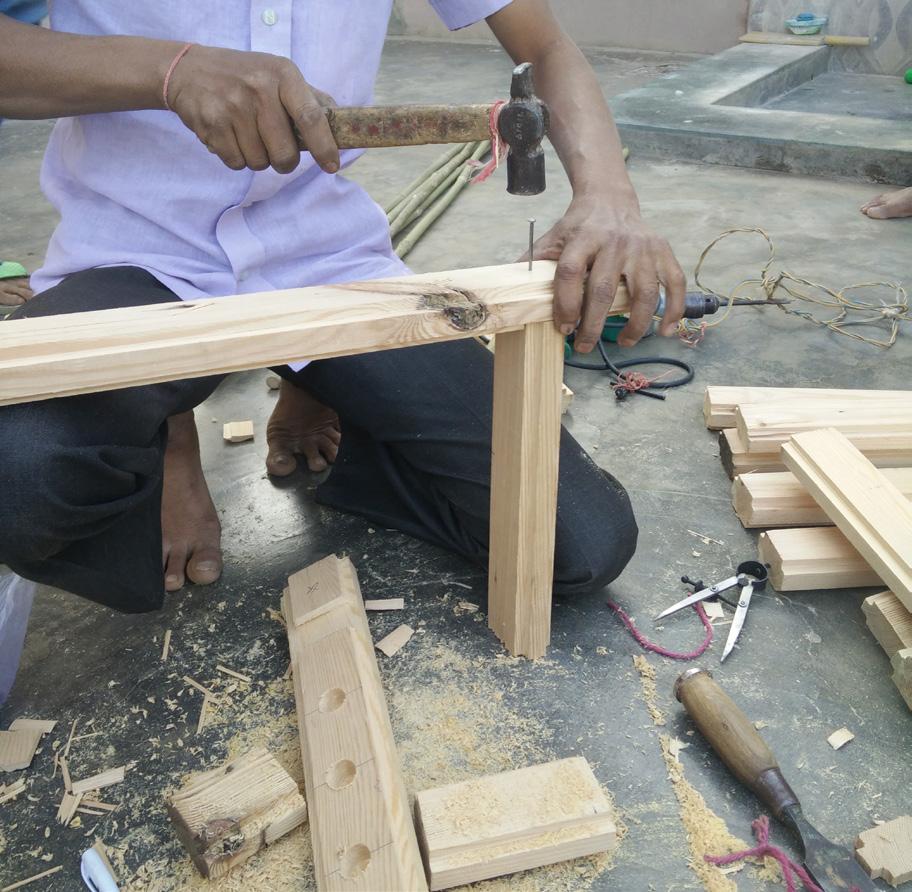
Nailing vertical wooden members to horizontal one The vertical wooden members are nailed to the horizontal wooden members of the frame. Hold-fasts were then attached to the vertical members of the frame.
Fixing the bamboo sticks The bamboo sticks were then fit into the dead hole and tightened with a little pressure.
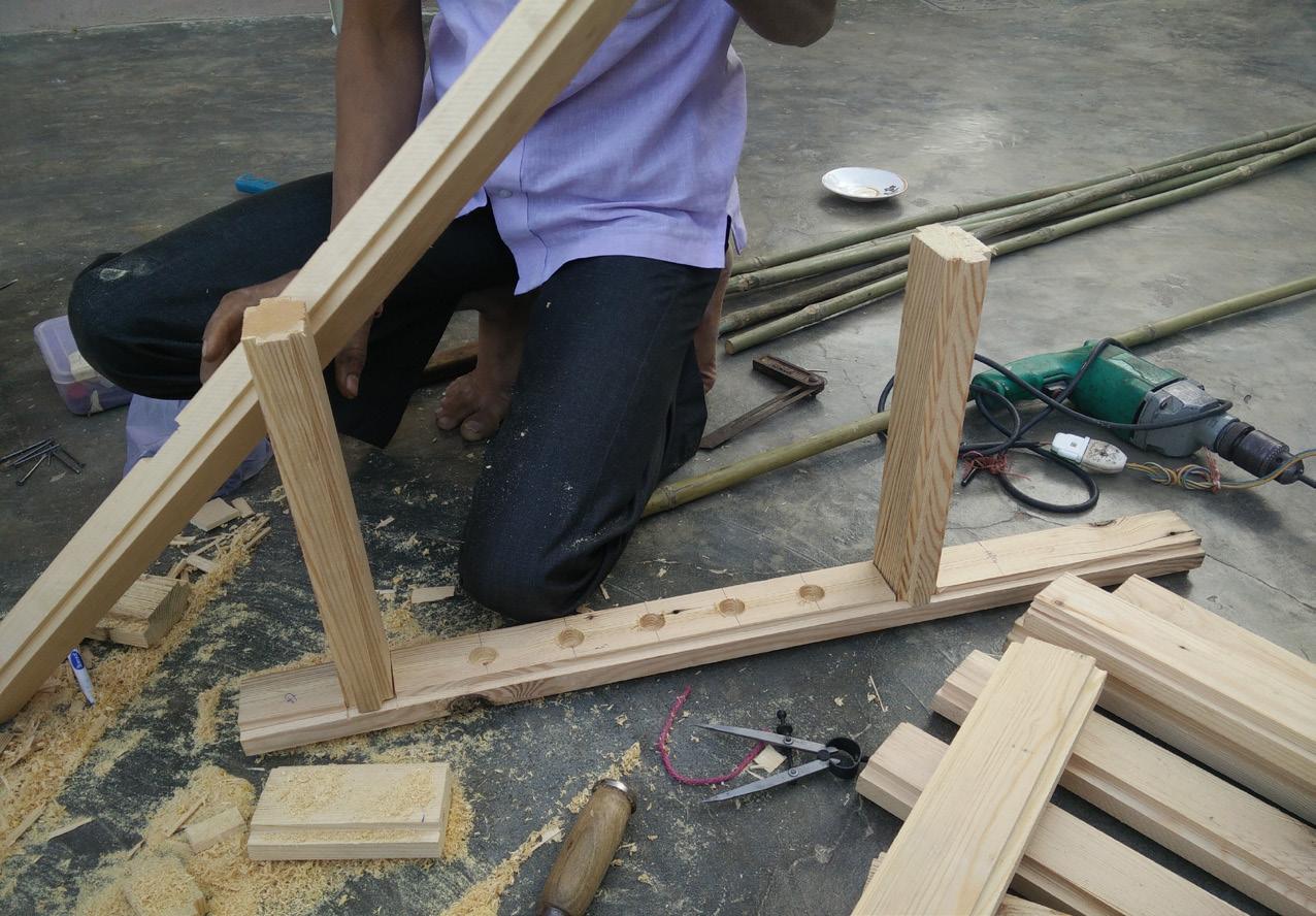
Then the second horizontal member was nailed to the two fixed vertical members.
Nailing the horizontal member to the vertical one
17.1 Fixing the Window
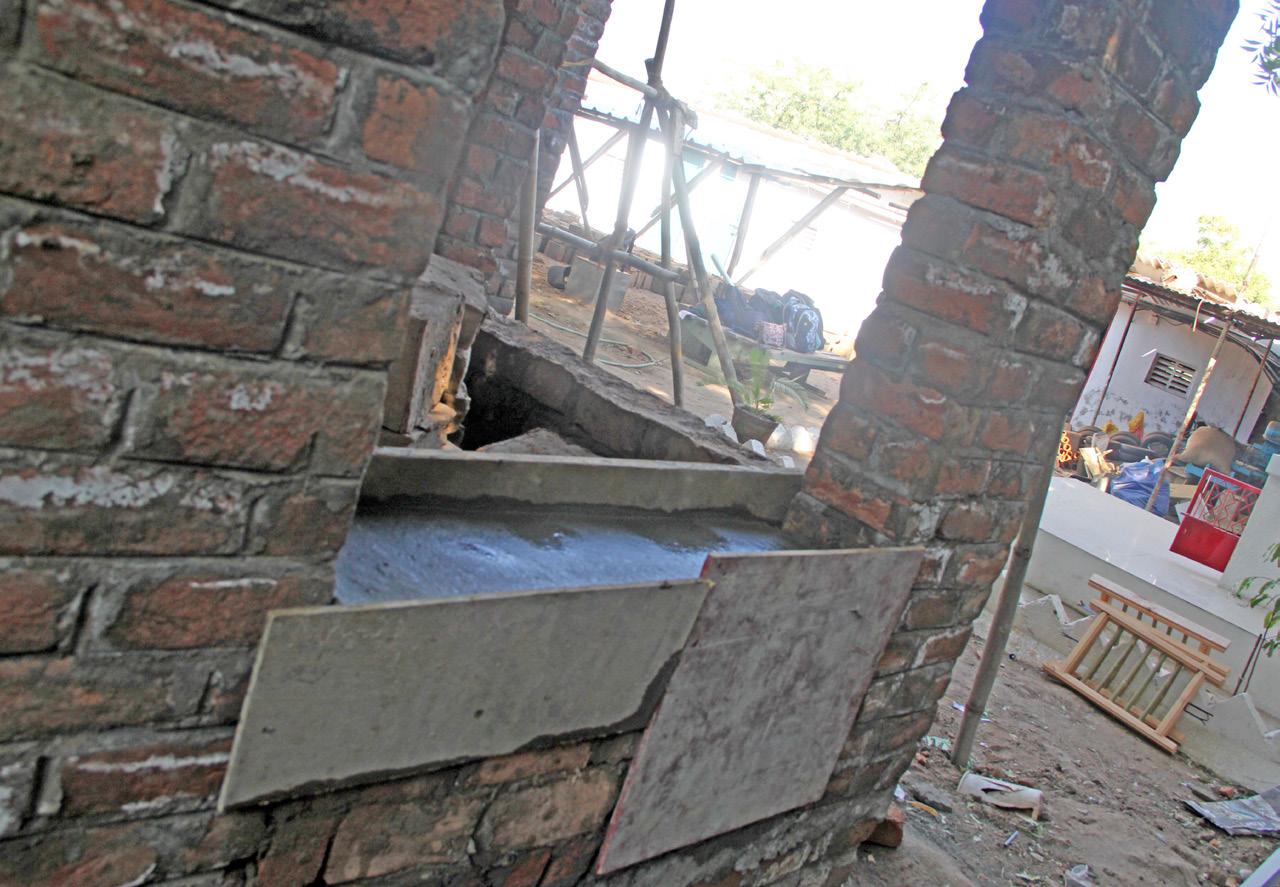
Casting of concrete band A concrete band, was cast at the Sill level for giving an even base to the window and aligning it properly without any inclination.
The wooden window was placed above the concrete band at Sill level.
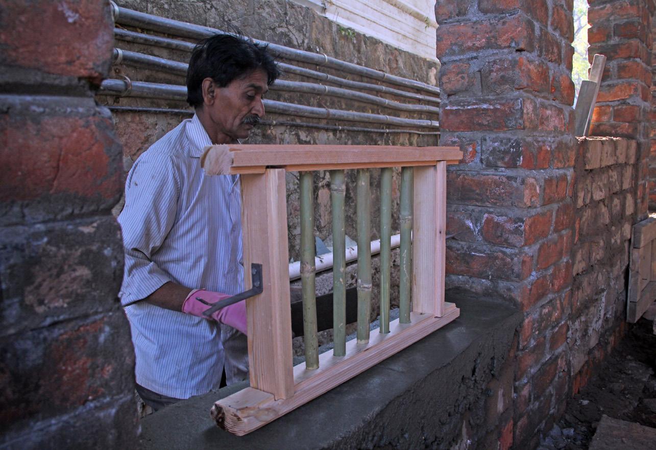
The wall on both the sides of the window were made with brick masonry in order to strengthen the connection between window and wall.
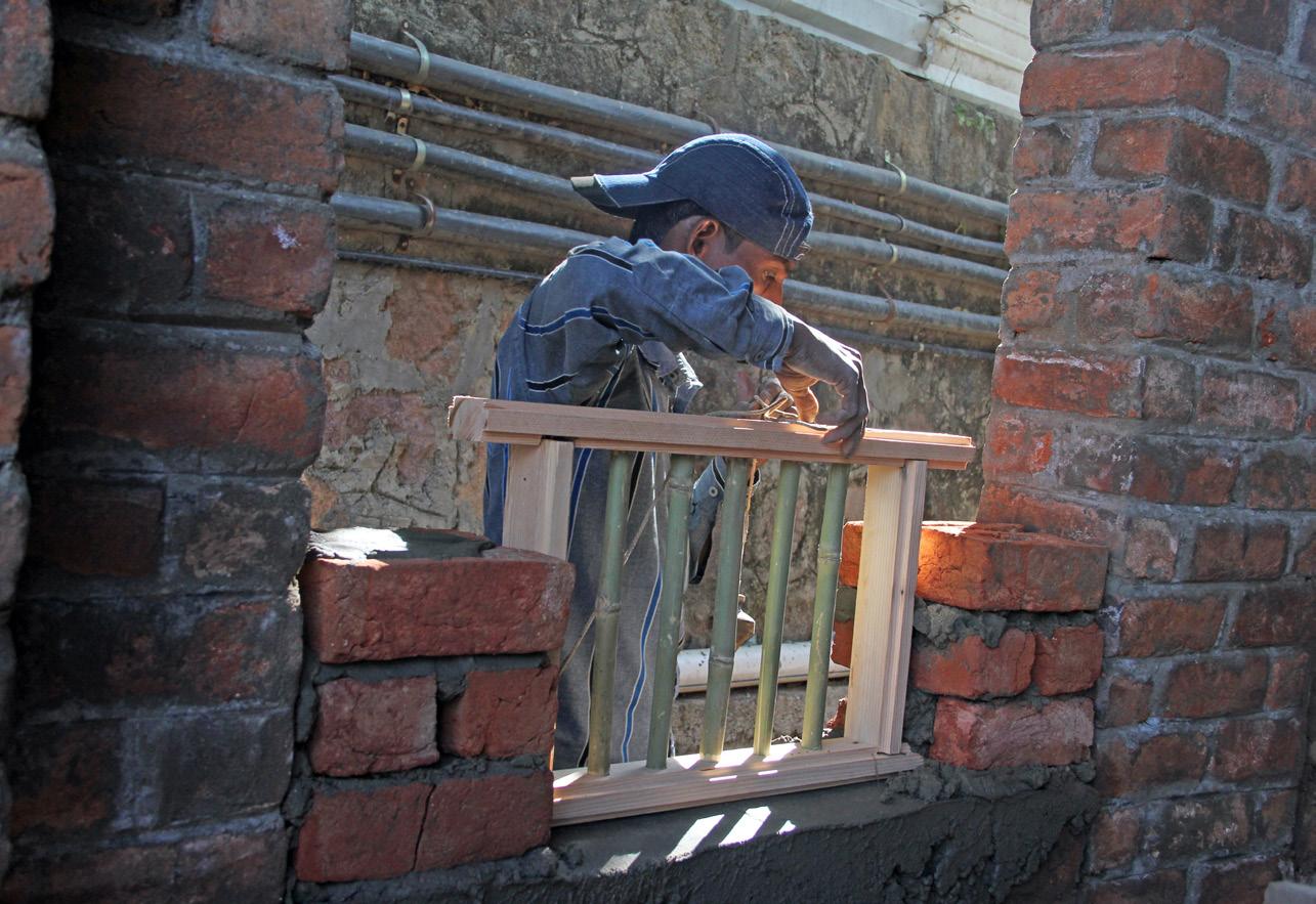
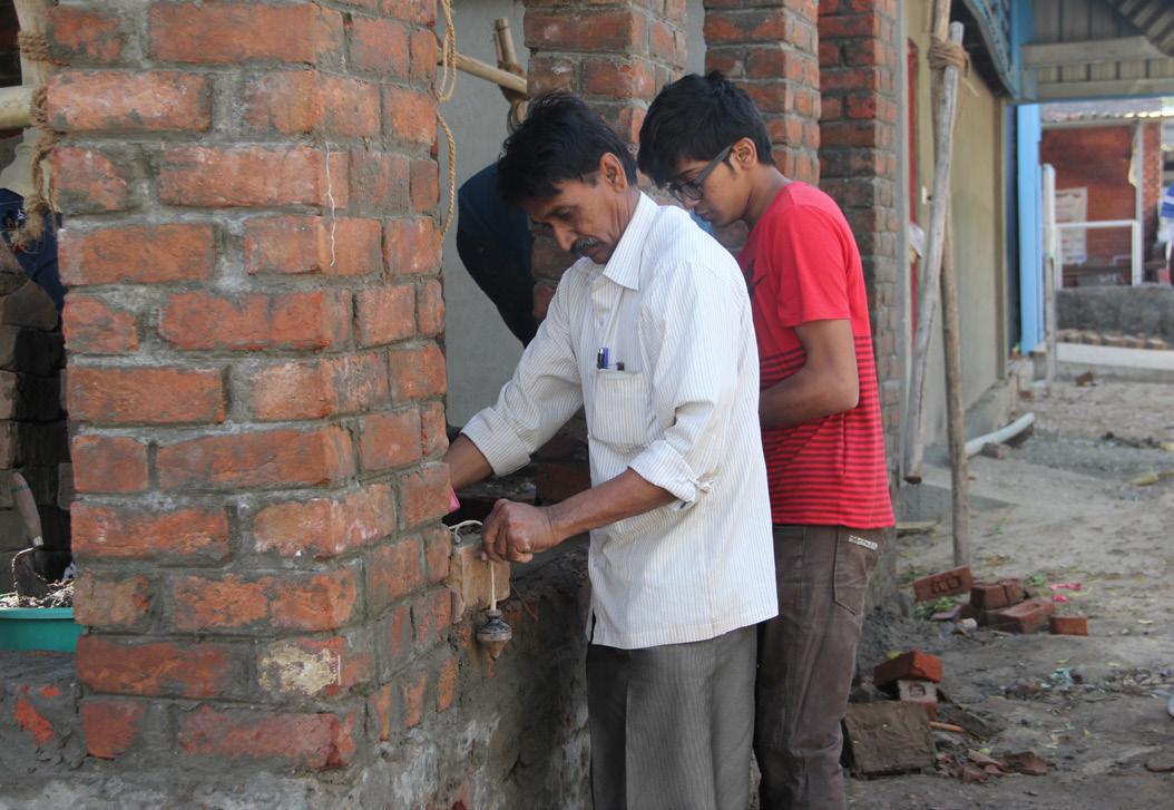
Securing the anchor-fastner
After reaching the lintel level, a Kota stone of 18mm thickness was placed.
18.1 Internal finish

The closed spaces are internally finished with Mud Plaster, in order to keep it as natural and simple as possible.
18.2 Pointing

Pointing done on the external facade In order to prevent rain water to enter the gaps between mud bricks pointing was done on external surfaces of wall.
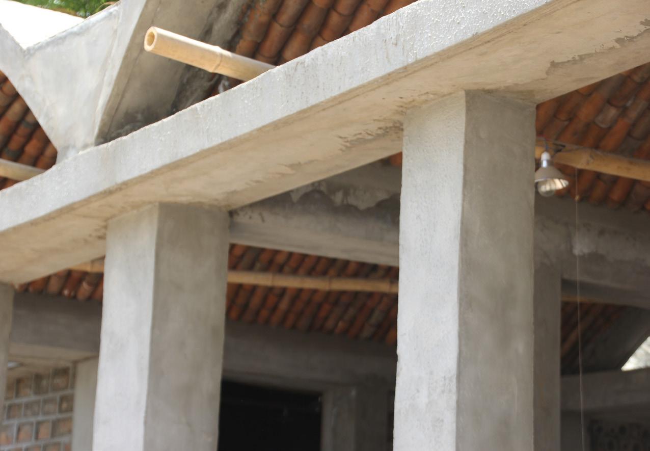
Cement plaster applied to all the structural members All the elements of the semi-open spaces are finished with cement plaster, so it can withstand against rain water.
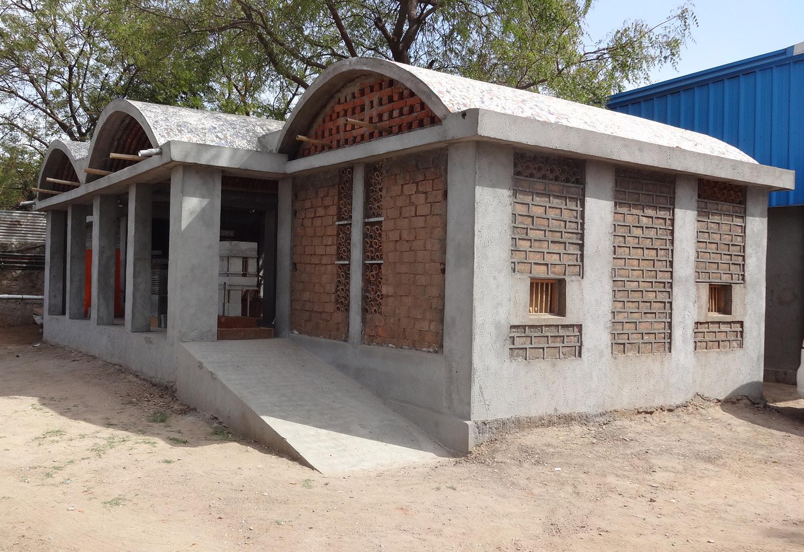
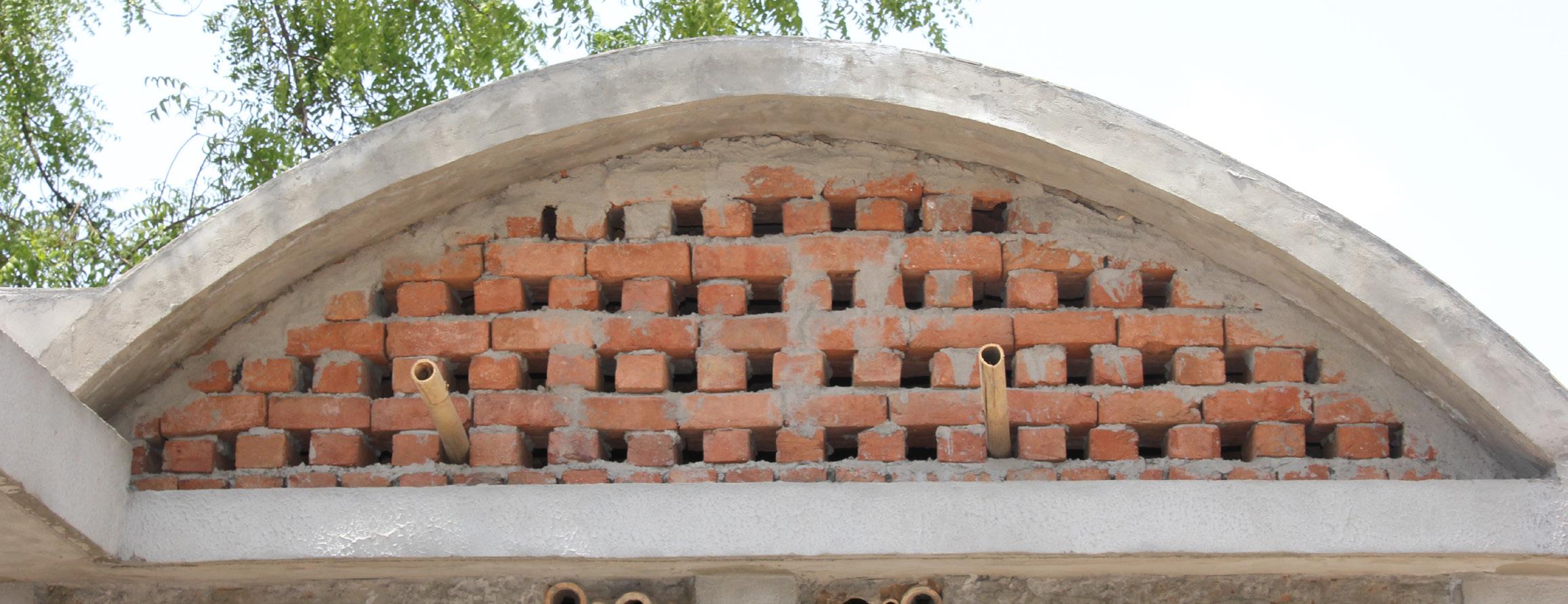
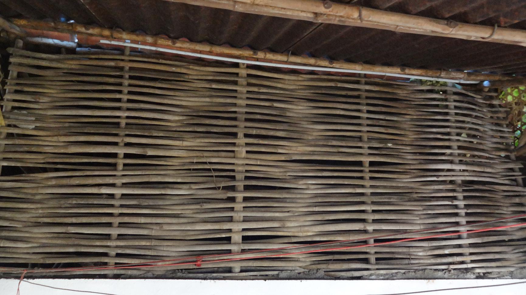
Brick jali
The brick jali was used to close the vault from both the sides in the closed spaces. The main reason behind having the small opening and not closing the whole space was to let the natural light come in.
The ramp was placed at the entrance of the structure instead of steps. Ramp allows easier access.
Construction details are shown below.
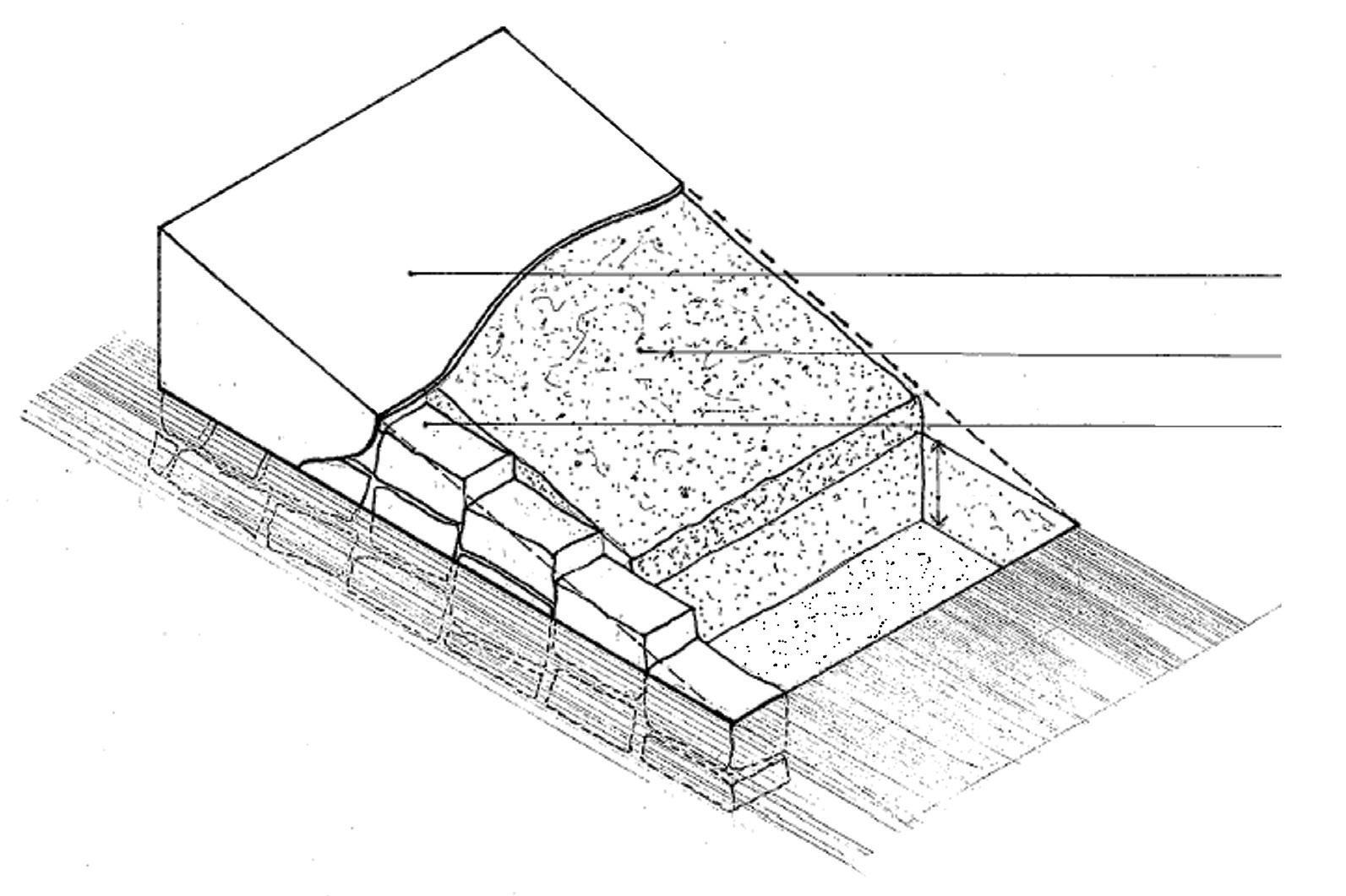
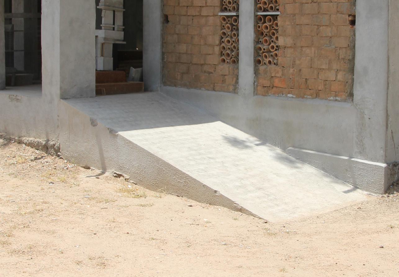
Ramp created at the entrance
25mm Thick Cement Mortar layer
100mm thick Pcc 450*300*150mm thick stone retaining wall
Isometric detail of the ramp

Steps created at the exit The steps were made at the back of the structure, which in return also worked as an exit. The steps are built in brick masonry and plastered with cement mortar for finishing.
300mm down One Brick Thick Course Brick courses 25mm Thick Cement Plaster 150mm riser and 300mm trade
Brick masonry used to make steps
IPS flooring 35mm Thick IPS Flooring
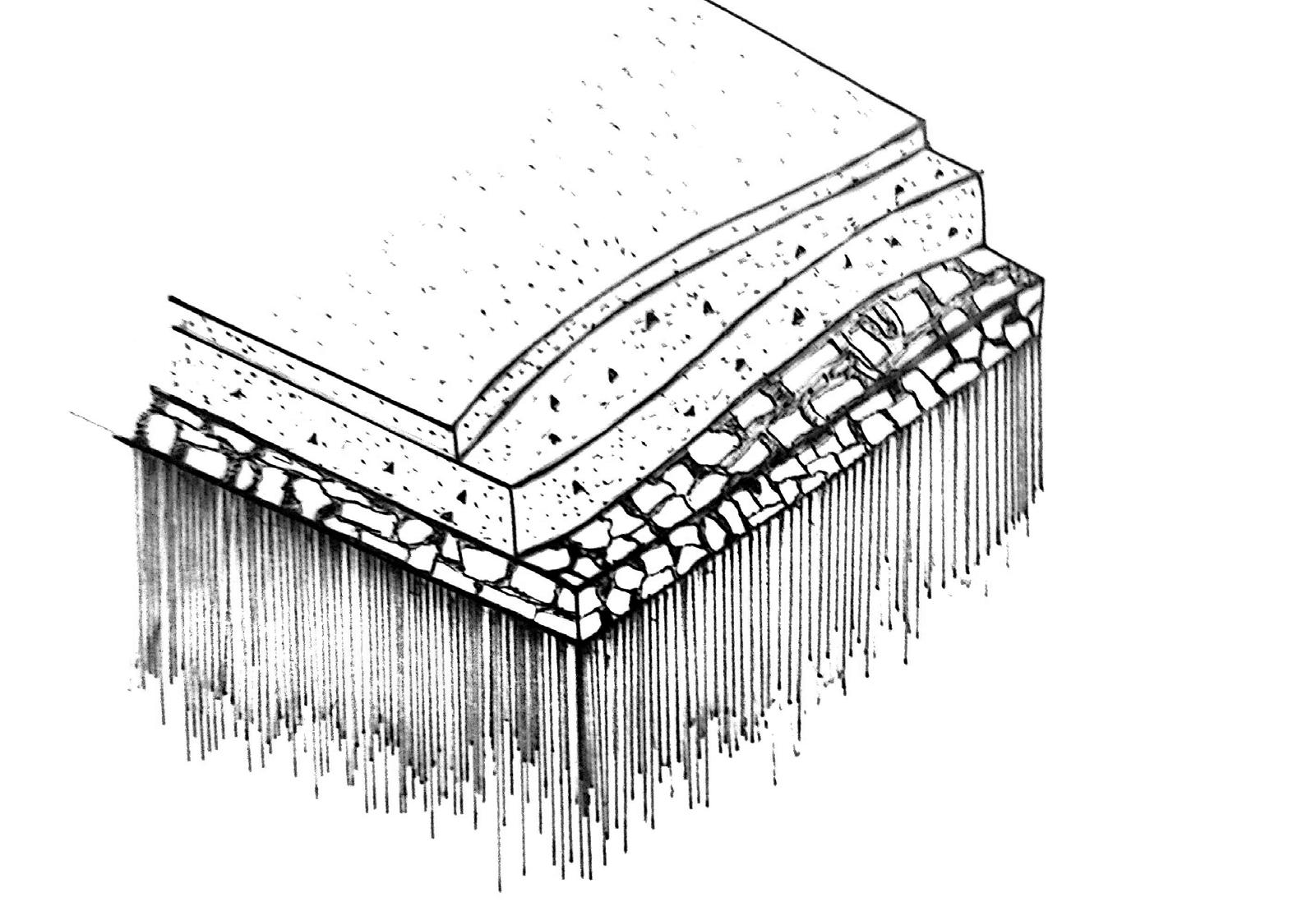
100mm PCC
100mm BBCC
Compacted Earth